EP4471354A1 - Air conditioner and air conditioner control method - Google Patents
Air conditioner and air conditioner control method Download PDFInfo
- Publication number
- EP4471354A1 EP4471354A1 EP22923771.4A EP22923771A EP4471354A1 EP 4471354 A1 EP4471354 A1 EP 4471354A1 EP 22923771 A EP22923771 A EP 22923771A EP 4471354 A1 EP4471354 A1 EP 4471354A1
- Authority
- EP
- European Patent Office
- Prior art keywords
- refrigerant
- heat exchanger
- expansion valve
- air
- switching mechanism
- Prior art date
- Legal status (The legal status is an assumption and is not a legal conclusion. Google has not performed a legal analysis and makes no representation as to the accuracy of the status listed.)
- Pending
Links
Images

Classifications
-
- F—MECHANICAL ENGINEERING; LIGHTING; HEATING; WEAPONS; BLASTING
- F25—REFRIGERATION OR COOLING; COMBINED HEATING AND REFRIGERATION SYSTEMS; HEAT PUMP SYSTEMS; MANUFACTURE OR STORAGE OF ICE; LIQUEFACTION SOLIDIFICATION OF GASES
- F25B—REFRIGERATION MACHINES, PLANTS OR SYSTEMS; COMBINED HEATING AND REFRIGERATION SYSTEMS; HEAT PUMP SYSTEMS
- F25B13/00—Compression machines, plants or systems, with reversible cycle
-
- F—MECHANICAL ENGINEERING; LIGHTING; HEATING; WEAPONS; BLASTING
- F25—REFRIGERATION OR COOLING; COMBINED HEATING AND REFRIGERATION SYSTEMS; HEAT PUMP SYSTEMS; MANUFACTURE OR STORAGE OF ICE; LIQUEFACTION SOLIDIFICATION OF GASES
- F25B—REFRIGERATION MACHINES, PLANTS OR SYSTEMS; COMBINED HEATING AND REFRIGERATION SYSTEMS; HEAT PUMP SYSTEMS
- F25B41/00—Fluid-circulation arrangements
- F25B41/20—Disposition of valves, e.g. of on-off valves or flow control valves
-
- F—MECHANICAL ENGINEERING; LIGHTING; HEATING; WEAPONS; BLASTING
- F25—REFRIGERATION OR COOLING; COMBINED HEATING AND REFRIGERATION SYSTEMS; HEAT PUMP SYSTEMS; MANUFACTURE OR STORAGE OF ICE; LIQUEFACTION SOLIDIFICATION OF GASES
- F25B—REFRIGERATION MACHINES, PLANTS OR SYSTEMS; COMBINED HEATING AND REFRIGERATION SYSTEMS; HEAT PUMP SYSTEMS
- F25B41/00—Fluid-circulation arrangements
- F25B41/20—Disposition of valves, e.g. of on-off valves or flow control valves
- F25B41/24—Arrangement of shut-off valves for disconnecting a part of the refrigerant cycle, e.g. an outdoor part
-
- F—MECHANICAL ENGINEERING; LIGHTING; HEATING; WEAPONS; BLASTING
- F25—REFRIGERATION OR COOLING; COMBINED HEATING AND REFRIGERATION SYSTEMS; HEAT PUMP SYSTEMS; MANUFACTURE OR STORAGE OF ICE; LIQUEFACTION SOLIDIFICATION OF GASES
- F25B—REFRIGERATION MACHINES, PLANTS OR SYSTEMS; COMBINED HEATING AND REFRIGERATION SYSTEMS; HEAT PUMP SYSTEMS
- F25B41/00—Fluid-circulation arrangements
- F25B41/40—Fluid line arrangements
-
- F—MECHANICAL ENGINEERING; LIGHTING; HEATING; WEAPONS; BLASTING
- F25—REFRIGERATION OR COOLING; COMBINED HEATING AND REFRIGERATION SYSTEMS; HEAT PUMP SYSTEMS; MANUFACTURE OR STORAGE OF ICE; LIQUEFACTION SOLIDIFICATION OF GASES
- F25B—REFRIGERATION MACHINES, PLANTS OR SYSTEMS; COMBINED HEATING AND REFRIGERATION SYSTEMS; HEAT PUMP SYSTEMS
- F25B49/00—Arrangement or mounting of control or safety devices
- F25B49/02—Arrangement or mounting of control or safety devices for compression type machines, plants or systems
-
- F—MECHANICAL ENGINEERING; LIGHTING; HEATING; WEAPONS; BLASTING
- F25—REFRIGERATION OR COOLING; COMBINED HEATING AND REFRIGERATION SYSTEMS; HEAT PUMP SYSTEMS; MANUFACTURE OR STORAGE OF ICE; LIQUEFACTION SOLIDIFICATION OF GASES
- F25B—REFRIGERATION MACHINES, PLANTS OR SYSTEMS; COMBINED HEATING AND REFRIGERATION SYSTEMS; HEAT PUMP SYSTEMS
- F25B2313/00—Compression machines, plants or systems with reversible cycle not otherwise provided for
- F25B2313/027—Compression machines, plants or systems with reversible cycle not otherwise provided for characterised by the reversing means
- F25B2313/02742—Compression machines, plants or systems with reversible cycle not otherwise provided for characterised by the reversing means using two four-way valves
-
- F—MECHANICAL ENGINEERING; LIGHTING; HEATING; WEAPONS; BLASTING
- F25—REFRIGERATION OR COOLING; COMBINED HEATING AND REFRIGERATION SYSTEMS; HEAT PUMP SYSTEMS; MANUFACTURE OR STORAGE OF ICE; LIQUEFACTION SOLIDIFICATION OF GASES
- F25B—REFRIGERATION MACHINES, PLANTS OR SYSTEMS; COMBINED HEATING AND REFRIGERATION SYSTEMS; HEAT PUMP SYSTEMS
- F25B2400/00—Component parts or details not otherwise provided for in this subclass
- F25B2400/05—Compression system with heat exchange between particular parts of the system
- F25B2400/054—Compression system with heat exchange between particular parts of the system between the suction tube of the compressor and another part of the cycle
-
- F—MECHANICAL ENGINEERING; LIGHTING; HEATING; WEAPONS; BLASTING
- F25—REFRIGERATION OR COOLING; COMBINED HEATING AND REFRIGERATION SYSTEMS; HEAT PUMP SYSTEMS; MANUFACTURE OR STORAGE OF ICE; LIQUEFACTION SOLIDIFICATION OF GASES
- F25B—REFRIGERATION MACHINES, PLANTS OR SYSTEMS; COMBINED HEATING AND REFRIGERATION SYSTEMS; HEAT PUMP SYSTEMS
- F25B2600/00—Control issues
-
- F—MECHANICAL ENGINEERING; LIGHTING; HEATING; WEAPONS; BLASTING
- F25—REFRIGERATION OR COOLING; COMBINED HEATING AND REFRIGERATION SYSTEMS; HEAT PUMP SYSTEMS; MANUFACTURE OR STORAGE OF ICE; LIQUEFACTION SOLIDIFICATION OF GASES
- F25B—REFRIGERATION MACHINES, PLANTS OR SYSTEMS; COMBINED HEATING AND REFRIGERATION SYSTEMS; HEAT PUMP SYSTEMS
- F25B2600/00—Control issues
- F25B2600/25—Control of valves
-
- F—MECHANICAL ENGINEERING; LIGHTING; HEATING; WEAPONS; BLASTING
- F25—REFRIGERATION OR COOLING; COMBINED HEATING AND REFRIGERATION SYSTEMS; HEAT PUMP SYSTEMS; MANUFACTURE OR STORAGE OF ICE; LIQUEFACTION SOLIDIFICATION OF GASES
- F25B—REFRIGERATION MACHINES, PLANTS OR SYSTEMS; COMBINED HEATING AND REFRIGERATION SYSTEMS; HEAT PUMP SYSTEMS
- F25B2700/00—Sensing or detecting of parameters; Sensors therefor
- F25B2700/19—Pressures
- F25B2700/193—Pressures of the compressor
- F25B2700/1933—Suction pressures
Definitions
- the internal heat exchanger of the air-conditioning apparatus disclosed in Patent Literature 1 cools the refrigerant output from the outdoor heat exchanger during the cooling operation.
- This air-conditioning apparatus has improved cooling performance.
- the air-conditioning apparatus also includes two indoor heat exchangers, one of which functions as an evaporator and the other of which functions as a condenser. During an operation of heating the room including the other indoor heat exchanger, the air-conditioning apparatus closes a switching valve provided between the compressors and the bifurcation, and thus allows the internal heat exchanger to serve as a reservoir for excess refrigerant.
- the air-conditioning apparatus therefore has improved heating performance.
- Patent Literature 1 Unexamined Japanese Patent Application Publication No. H4-257661
- An objective of the present disclosure which has been accomplished to solve the above problem, is to provide an air-conditioning apparatus having improved cooling performance and improved heating performance with a simple structure, and a method of controlling the air-conditioning apparatus.
- an air-conditioning apparatus includes a refrigerant circuit, an internal heat exchanger, and a controller.
- the refrigerant circuit includes an outdoor heat exchanger to perform heat exchange between refrigerant and outdoor air, a first expansion valve to expand the refrigerant, an indoor heat exchanger to perform heat exchange between the refrigerant and indoor air, a compressor to compress the refrigerant, and a first switching mechanism to switch the direction of a flow of the refrigerant.
- the outdoor heat exchanger, the first expansion valve, the indoor heat exchanger, and the first switching mechanism are coupled to each other in sequence.
- the compressor is coupled to the first switching mechanism.
- the internal heat exchanger has a first channel leading to the first switching mechanism and the compressor, and a second channel leading to a bifurcation and a second switching mechanism.
- the bifurcation is included in a refrigerant pipe that couples the outdoor heat exchanger to the first expansion valve.
- the second switching mechanism is disposed at a position in the refrigerant pipe more adjacent to the first expansion valve than to the bifurcation and configured to switch the flow of the refrigerant.
- the internal heat exchanger is configured to perform heat exchange between the refrigerant flowing through the first channel and the refrigerant flowing through the second channel.
- the controller switches the second switching mechanism such that the second channel is connected to the first expansion valve, and thus causes the refrigerant after the heat exchange performed by the internal heat exchanger to flow to the first expansion valve, in a process of causing the indoor heat exchanger to cool the indoor air.
- the controller switches the second switching mechanism such that the second channel is disconnected from the first expansion valve, and thus stops the flow of the refrigerant from the second channel to the first expansion valve, in a process of causing the indoor heat exchanger to heat the indoor air.
- the controller switches the second switching mechanism such that the second channel is connected to the first expansion valve, and thus causes the refrigerant after the heat exchange performed by the internal heat exchanger to flow to the first expansion valve, in a process of causing the indoor heat exchanger to cool the indoor air.
- the refrigerant to flow via the first expansion valve to the indoor heat exchanger thus has a lower temperature. This configuration can therefore improve the cooling performance of the air-conditioning apparatus.
- the air-conditioning apparatus is designed for conditioning the indoor air of a railway vehicle.
- This air-conditioning apparatus includes, as well as an indoor heat exchanger and an outdoor heat exchanger, an internal heat exchanger aimed at improving the cooling performance.
- the air-conditioning apparatus also includes a controller that switches three-way valves and thus causes refrigerant to flow to the internal heat exchanger during a cooling operation.
- the air-conditioning apparatus to be controlled by the controller is described below with reference to FIG. 1 .
- the air-conditioning apparatus 1 includes a compressor 10 that compresses refrigerant, three-way valves 21 and 22 that switch the directions of refrigerant flows, an outdoor heat exchanger 30 that performs heat exchange between the refrigerant and the outdoor air, expansion valves 41 and 42 that expand the refrigerant, and an indoor heat exchanger 50 that performs heat exchange between the refrigerant and the indoor air.
- the compressor 10, the three-way valves 21 and 22, the outdoor heat exchanger 30, the expansion valves 41 and 42, and the indoor heat exchanger 50 are connected to each other in sequence and constitute a refrigerant circuit 2.
- the compressor 10 compresses low-pressure refrigerant and thus converts the refrigerant into high-pressure refrigerant.
- the compressor 10 has an inlet and an outlet, which are not illustrated.
- the compressor 10 introduces low-pressure refrigerant through the inlet and discharges high-pressure refrigerant through the outlet.
- the inlet is coupled to an internal heat exchanger 60, which is described below.
- the outlet is coupled to the three-way valve 21 via a check valve 11, which allows refrigerant to flow in the direction from the compressor 10 toward the three-way valve 21 and does not allow refrigerant to flow in the opposite direction.
- the three-way valves 21 and 22 are coupled in parallel to each other.
- the three-way valve 21 has three ports.
- the three ports include a first port coupled to a branch pipe of a refrigerant pipe 31 leading to the outdoor heat exchanger 30.
- the three ports include a second port coupled to a refrigerant pipe 12 extending from the compressor 10.
- the three ports further include a third port coupled to a branch pipe of a refrigerant pipe 51 leading to the indoor heat exchanger 50.
- the three-way valve 22 also has a first port, a second port, and a third port.
- the first port is coupled to another branch pipe of the refrigerant pipe 31.
- the second port is coupled to a refrigerant pipe 63 extending from the internal heat exchanger 60.
- the third port is coupled to another branch pipe of the refrigerant pipe 51.
- the three-way valves 21 and 22 are each a solenoid valve or a motorized valve, for example.
- the three-way valves 21 and 22 are electrically coupled to the controller 80, which is described below.
- the three-way valves 21 and 22 guide the refrigerant introduced from the compressor 10 through the refrigerant pipe 12, to the refrigerant pipe 31 leading to the outdoor heat exchanger 30, in response to a switching operation by the controller 80.
- the three-way valves 21 and 22 guide the refrigerant output from the indoor heat exchanger 50 through the refrigerant pipe 51, to the refrigerant pipe 63 leading to the internal heat exchanger 60.
- the three-way valves 21 and 22 thus turn the operation mode of the air-conditioning apparatus 1 into a cooling mode.
- the three-way valves 21 and 22 guide the refrigerant introduced from the compressor 10, to the refrigerant pipe 51 leading to the indoor heat exchanger 50, in response to another switching operation by the controller 80.
- the three-way valves 21 and 22 guide the refrigerant output from the outdoor heat exchanger 30 through the refrigerant pipe 31, to the refrigerant pipe 63 leading to the internal heat exchanger 60.
- the three-way valves 21 and 22 thus turn the operation mode of the air-conditioning apparatus 1 into a heating mode.
- the three-way valves 21 and 22 switch the directions of refrigerant flows in the refrigerant circuit 2, and thus achieve the cooling mode or the heating mode of the air-conditioning apparatus 1.
- the three-way valves 21 and 22 accordingly guide the refrigerant compressed by the compressor 10 to the outdoor heat exchanger 30 or the indoor heat exchanger 50.
- the outdoor heat exchanger 30 has a finned tube structure.
- the outdoor heat exchanger 30 has multiple fins and tubes, which are not illustrated.
- the fins are fed with the outdoor air by a fan, which is not illustrated.
- the tubes allow the refrigerant from the compressor 10 to flow through the tubes during the cooling operation, or allow the refrigerant from an expansion valve 41 to flow through the tubes during the heating operation.
- the outdoor heat exchanger 30 having this structure performs heat exchange between the outdoor air fed to the fins and the refrigerant flowing through the tubes, and condenses the refrigerant during the cooling operation, or evaporates the refrigerant during the heating operation.
- the outdoor heat exchanger 30 thus functions as a condenser during the cooling operation, or functions as an evaporator during the heating operation.
- the outdoor heat exchanger 30 outputs the refrigerant to an expansion valve 42 illustrated in FIG. 1 during the cooling operation, or outputs the refrigerant to the three-way valves 21 and 22 during the heating operation.
- the expansion valves 41 and 42 each have a valve body, which is not illustrated, to adjust the aperture of a flow path of refrigerant.
- the expansion valves 41 and 42 are each a solenoid valve or a motorized valve, for example.
- the expansion valves 41 and 42 are electrically connected to the controller 80 illustrated in FIG. 1 , and adjust the apertures of the valve bodies that define the flow paths in accordance with the output from the controller 80.
- the expansion valves 41 and 42 decrease the pressure of the refrigerant by means of the apertures of the valve bodies.
- the expansion valves 41 and 42 decrease the pressure of the refrigerant to a pressure depending on the output from the controller 80 and thus expand the refrigerant.
- the expansion valves 41 and 42 are aimed at expanding refrigerant during the heating operation and the cooling operation, respectively.
- the expansion valve 41 is coupled in parallel to a check valve 68, so that the expansion valve 41 is used only in the heating operation and not used in the cooling operation.
- the check valve 68 allows refrigerant to flow in the direction from a refrigerant pipe 32 having a bifurcation between the expansion valve 41 and the outdoor heat exchanger 30 toward the internal heat exchanger 60 or toward the indoor heat exchanger 50, and does not allow refrigerant to flow in the opposite direction.
- the expansion valve 42 is coupled in parallel to a check valve 46, so that the expansion valve 42 is used only in the cooling operation and not used in the heating operation.
- the check valve 46 allows refrigerant to flow in the direction from the indoor heat exchanger 50 toward the outdoor heat exchanger 30, and does not allow refrigerant to flow in the opposite direction.
- the expansion valves 41 and 42 are controlled by the controller 80, such that the apertures of the individual valve bodies are adjusted depending on whether the current mode is the cooling mode or the heating mode.
- the expansion valve 42 expands refrigerant and outputs the expanded refrigerant to the indoor heat exchanger 50.
- the expansion valve 41 expands refrigerant and outputs the expanded refrigerant to the outdoor heat exchanger 30.
- the indoor heat exchanger 50 has a finned tube structure, like the outdoor heat exchanger 30.
- the indoor heat exchanger 50 has fins, which are not illustrated, like the outdoor heat exchanger 30.
- the fins are fed with the indoor air by a fan, which is not illustrated.
- the indoor heat exchanger 50 also has tubes, which are not illustrated.
- the tubes allow the refrigerant expanded by the expansion valve 42 to flow through the tubes during the cooling operation, or allow the refrigerant compressed by the compressor 10 to flow through the tubes during the heating operation.
- the indoor heat exchanger 50 having this structure performs heat exchange between the fed indoor air and the refrigerant flowing through the tubes.
- This indoor heat exchanger 50 functions as an evaporator that absorbs heat from the indoor air and evaporates the refrigerant during the cooling operation, or functions as a condenser that discharges heat to the indoor air and condenses the refrigerant during the heating operation.
- the indoor heat exchanger 50 accordingly cools the indoor air during the cooling operation, or heats the indoor air during the heating operation.
- the indoor heat exchanger 50 returns the refrigerant to the three-way valves 21 and 22 during the cooling operation, or outputs the refrigerant to the expansion valve 41 during the heating operation.
- the refrigerant circuit 2 which enables the air-conditioning apparatus 1 to perform the cooling operation or the heating operation. These operations basically require the condenser to discharge the heat absorbed from the air by the evaporator and the input heat generated by compression. The condenser thus must have heat exchange performance superior to that of the evaporator.
- the refrigerant contains a material existing in nature, in terms of environmental conservation. In detail, the refrigerant is made of carbon dioxide, that is, CO 2 .
- the outdoor heat exchanger 30 serving as a condenser during the cooling operation thus preferably has a large volumetric capacity like a heat exchanger called gas cooler.
- the outdoor heat exchanger 30 is designed to have a volumetric capacity for accommodating refrigerant that is even larger than the volumetric capacity of the indoor heat exchanger 50 for accommodating refrigerant, in comparison to that of an air-conditioning apparatus using condensable refrigerant.
- the indoor heat exchanger 50 having a smaller volumetric capacity than the outdoor heat exchanger 30 and serving as a condenser during the heating operation will suffer from excess refrigerant.
- excess refrigerant unintentionally increases the temperature and pressure of the refrigerant flowing through the indoor heat exchanger 30 during the heating operation, thereby impairing the heating performance of the air-conditioning apparatus 1.
- the air-conditioning apparatus 1 further includes the internal heat exchanger 60 aimed at improving the cooling performance, and a three-way valve 70 that switches the direction of a refrigerant flow to the internal heat exchanger 60 and thus allows the internal heat exchanger 60 to reserve excess refrigerant during the heating operation.
- control program is stored in the ROM 83 in the embodiment, the control program may also be stored in a non-transitory computer-readable recording medium, such as flexile disc, compact disc read-only memory (CD-ROM), digital versatile disc (DVD), or magneto-optical disc (MO), and distributed.
- control program stored in the non-transitory recording medium may be installed in a computer to configure the controller 80 that executes the control process.
Landscapes
- Engineering & Computer Science (AREA)
- Physics & Mathematics (AREA)
- Mechanical Engineering (AREA)
- Thermal Sciences (AREA)
- General Engineering & Computer Science (AREA)
- Compression-Type Refrigeration Machines With Reversible Cycles (AREA)
Abstract
Description
- The present disclosure relates to an air-conditioning apparatus and a method of controlling an air-conditioning apparatus.
- Some air-conditioning apparatuses include an internal heat exchanger that cools the refrigerant output from an outdoor heat exchanger during a cooling operation.
- For example, Patent Literature 1 discloses an air-conditioning apparatus including compressors that compress refrigerant, a bifurcation provided to a high-pressure liquid pipe through which the refrigerant output from an outdoor heat exchanger flows, and an internal heat exchanger disposed between the compressors and the bifurcation. The internal heat exchanger performs heat exchange between the refrigerant separated at the bifurcation and cooled through decompression by an expansion device and the refrigerant just separated at the bifurcation during a cooling operation, and thus cools the refrigerant just separated at the bifurcation, and then returns the refrigerant to the high-pressure liquid pipe.
- The internal heat exchanger of the air-conditioning apparatus disclosed in Patent Literature 1 cools the refrigerant output from the outdoor heat exchanger during the cooling operation. This air-conditioning apparatus has improved cooling performance. The air-conditioning apparatus also includes two indoor heat exchangers, one of which functions as an evaporator and the other of which functions as a condenser. During an operation of heating the room including the other indoor heat exchanger, the air-conditioning apparatus closes a switching valve provided between the compressors and the bifurcation, and thus allows the internal heat exchanger to serve as a reservoir for excess refrigerant. The air-conditioning apparatus therefore has improved heating performance.
- Patent Literature 1: Unexamined
Japanese Patent Application Publication No. H4-257661 - The air-conditioning apparatus disclosed in Patent Literature 1, however, has a complicated structure because of the expansion device included in the internal heat exchanger to decrease the pressure of the refrigerant.
- An objective of the present disclosure, which has been accomplished to solve the above problem, is to provide an air-conditioning apparatus having improved cooling performance and improved heating performance with a simple structure, and a method of controlling the air-conditioning apparatus.
- In order to achieve the above objective, an air-conditioning apparatus according to the present disclosure includes a refrigerant circuit, an internal heat exchanger, and a controller. The refrigerant circuit includes an outdoor heat exchanger to perform heat exchange between refrigerant and outdoor air, a first expansion valve to expand the refrigerant, an indoor heat exchanger to perform heat exchange between the refrigerant and indoor air, a compressor to compress the refrigerant, and a first switching mechanism to switch the direction of a flow of the refrigerant. The outdoor heat exchanger, the first expansion valve, the indoor heat exchanger, and the first switching mechanism are coupled to each other in sequence. The compressor is coupled to the first switching mechanism. The internal heat exchanger has a first channel leading to the first switching mechanism and the compressor, and a second channel leading to a bifurcation and a second switching mechanism. The bifurcation is included in a refrigerant pipe that couples the outdoor heat exchanger to the first expansion valve. The second switching mechanism is disposed at a position in the refrigerant pipe more adjacent to the first expansion valve than to the bifurcation and configured to switch the flow of the refrigerant. The internal heat exchanger is configured to perform heat exchange between the refrigerant flowing through the first channel and the refrigerant flowing through the second channel. The controller switches the second switching mechanism such that the second channel is connected to the first expansion valve, and thus causes the refrigerant after the heat exchange performed by the internal heat exchanger to flow to the first expansion valve, in a process of causing the indoor heat exchanger to cool the indoor air. The controller switches the second switching mechanism such that the second channel is disconnected from the first expansion valve, and thus stops the flow of the refrigerant from the second channel to the first expansion valve, in a process of causing the indoor heat exchanger to heat the indoor air.
- According to the present disclosure, the controller switches the second switching mechanism such that the second channel is connected to the first expansion valve, and thus causes the refrigerant after the heat exchange performed by the internal heat exchanger to flow to the first expansion valve, in a process of causing the indoor heat exchanger to cool the indoor air. The refrigerant to flow via the first expansion valve to the indoor heat exchanger thus has a lower temperature. This configuration can therefore improve the cooling performance of the air-conditioning apparatus.
- In addition, the controller switches the second switching mechanism such that the second channel is disconnected from the first expansion valve, and thus stops the flow of the refrigerant from the second channel to the first expansion valve, in a process of causing the indoor heat exchanger to heat the indoor air. The refrigerant that entered the second channel in the process of causing the indoor heat exchanger to heat the indoor air thus remains in the second channel. This configuration can prevent the refrigerant circuit from suffering from excess refrigerant during the heating operation. The configuration can therefore improve the heating performance of the air-conditioning apparatus.
- Furthermore, the internal heat exchanger has the second channel leading to the bifurcation and the second switching mechanism. The bifurcation is included in a refrigerant pipe that couples the outdoor heat exchanger to the first expansion valve. The second switching mechanism is disposed at a position in the refrigerant pipe more adjacent to the first expansion valve than to the bifurcation and configured to switch the direction of a flow of the refrigerant. That is, the controller can connect or disconnect the second channel to or from the refrigerant pipe just by switching the second switching mechanism. This configuration can improve the cooling performance and the heating performance of the air-conditioning apparatus. The air-conditioning apparatus can therefore achieve improved cooling performance and improved heating performance with a simple structure.
-
-
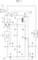
FIG. 1 illustrates a refrigerant circuit of an air-conditioning apparatus according to an embodiment of the present disclosure; -
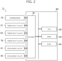
FIG. 2 illustrates a hardware configuration of a controller included in the air-conditioning apparatus according to the embodiment; -
FIG. 3 illustrates the refrigerant circuit with flows of refrigerant during a cooling operation in the air-conditioning apparatus according to the embodiment; and -
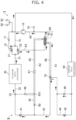
FIG. 4 illustrates the refrigerant circuit with flows of refrigerant during a heating operation in the air-conditioning apparatus according to the embodiment. - The following describes an air-conditioning apparatus and a method of controlling an air-conditioning apparatus according to an embodiment of the present disclosure in detail with reference to the accompanying drawings. In the drawings, the components identical or corresponding to each other are provided with the same reference symbol.
- The air-conditioning apparatus according to the embodiment is designed for conditioning the indoor air of a railway vehicle. This air-conditioning apparatus includes, as well as an indoor heat exchanger and an outdoor heat exchanger, an internal heat exchanger aimed at improving the cooling performance. The air-conditioning apparatus also includes a controller that switches three-way valves and thus causes refrigerant to flow to the internal heat exchanger during a cooling operation. The air-conditioning apparatus to be controlled by the controller is described below with reference to
FIG. 1 . -
FIG. 1 illustrates a refrigerant circuit of an air-conditioning apparatus 1 according to an embodiment.FIG. 1 illustrates, in addition to the individual components of the air-conditioning apparatus 1, electrical connections between acontroller 80 and the individual components with broken lines, in order to facilitate an understanding. - As illustrated in
FIG. 1 , the air-conditioning apparatus 1 includes acompressor 10 that compresses refrigerant, three-way valves outdoor heat exchanger 30 that performs heat exchange between the refrigerant and the outdoor air,expansion valves indoor heat exchanger 50 that performs heat exchange between the refrigerant and the indoor air. Thecompressor 10, the three-way valves outdoor heat exchanger 30, theexpansion valves indoor heat exchanger 50 are connected to each other in sequence and constitute arefrigerant circuit 2. - The
compressor 10 compresses low-pressure refrigerant and thus converts the refrigerant into high-pressure refrigerant. Thecompressor 10 has an inlet and an outlet, which are not illustrated. Thecompressor 10 introduces low-pressure refrigerant through the inlet and discharges high-pressure refrigerant through the outlet. The inlet is coupled to aninternal heat exchanger 60, which is described below. The outlet is coupled to the three-way valve 21 via acheck valve 11, which allows refrigerant to flow in the direction from thecompressor 10 toward the three-way valve 21 and does not allow refrigerant to flow in the opposite direction. - The three-
way valves way valve 21 has three ports. The three ports include a first port coupled to a branch pipe of arefrigerant pipe 31 leading to theoutdoor heat exchanger 30. The three ports include a second port coupled to arefrigerant pipe 12 extending from thecompressor 10. The three ports further include a third port coupled to a branch pipe of arefrigerant pipe 51 leading to theindoor heat exchanger 50. - The three-
way valve 22 also has a first port, a second port, and a third port. The first port is coupled to another branch pipe of therefrigerant pipe 31. The second port is coupled to arefrigerant pipe 63 extending from theinternal heat exchanger 60. The third port is coupled to another branch pipe of therefrigerant pipe 51. - The three-
way valves way valves controller 80, which is described below. The three-way valves compressor 10 through therefrigerant pipe 12, to therefrigerant pipe 31 leading to theoutdoor heat exchanger 30, in response to a switching operation by thecontroller 80. The three-way valves indoor heat exchanger 50 through therefrigerant pipe 51, to therefrigerant pipe 63 leading to theinternal heat exchanger 60. The three-way valves - Also, the three-
way valves compressor 10, to therefrigerant pipe 51 leading to theindoor heat exchanger 50, in response to another switching operation by thecontroller 80. The three-way valves outdoor heat exchanger 30 through therefrigerant pipe 31, to therefrigerant pipe 63 leading to theinternal heat exchanger 60. The three-way valves - That is, the three-
way valves refrigerant circuit 2, and thus achieve the cooling mode or the heating mode of the air-conditioning apparatus 1. The three-way valves compressor 10 to theoutdoor heat exchanger 30 or theindoor heat exchanger 50. - The
outdoor heat exchanger 30 has a finned tube structure. In detail, theoutdoor heat exchanger 30 has multiple fins and tubes, which are not illustrated. The fins are fed with the outdoor air by a fan, which is not illustrated. The tubes allow the refrigerant from thecompressor 10 to flow through the tubes during the cooling operation, or allow the refrigerant from anexpansion valve 41 to flow through the tubes during the heating operation. Theoutdoor heat exchanger 30 having this structure performs heat exchange between the outdoor air fed to the fins and the refrigerant flowing through the tubes, and condenses the refrigerant during the cooling operation, or evaporates the refrigerant during the heating operation. Theoutdoor heat exchanger 30 thus functions as a condenser during the cooling operation, or functions as an evaporator during the heating operation. Theoutdoor heat exchanger 30 outputs the refrigerant to anexpansion valve 42 illustrated inFIG. 1 during the cooling operation, or outputs the refrigerant to the three-way valves - The
expansion valves expansion valves expansion valves controller 80 illustrated inFIG. 1 , and adjust the apertures of the valve bodies that define the flow paths in accordance with the output from thecontroller 80. Theexpansion valves expansion valves controller 80 and thus expand the refrigerant. - The
expansion valves expansion valve 41 is coupled in parallel to acheck valve 68, so that theexpansion valve 41 is used only in the heating operation and not used in the cooling operation. Thecheck valve 68 allows refrigerant to flow in the direction from arefrigerant pipe 32 having a bifurcation between theexpansion valve 41 and theoutdoor heat exchanger 30 toward theinternal heat exchanger 60 or toward theindoor heat exchanger 50, and does not allow refrigerant to flow in the opposite direction. Theexpansion valve 42 is coupled in parallel to acheck valve 46, so that theexpansion valve 42 is used only in the cooling operation and not used in the heating operation. Thecheck valve 46 allows refrigerant to flow in the direction from theindoor heat exchanger 50 toward theoutdoor heat exchanger 30, and does not allow refrigerant to flow in the opposite direction. - The
expansion valves controller 80, such that the apertures of the individual valve bodies are adjusted depending on whether the current mode is the cooling mode or the heating mode. In the cooling mode, theexpansion valve 42 expands refrigerant and outputs the expanded refrigerant to theindoor heat exchanger 50. In the heating mode, theexpansion valve 41 expands refrigerant and outputs the expanded refrigerant to theoutdoor heat exchanger 30. - The
indoor heat exchanger 50 has a finned tube structure, like theoutdoor heat exchanger 30. In detail, theindoor heat exchanger 50 has fins, which are not illustrated, like theoutdoor heat exchanger 30. The fins are fed with the indoor air by a fan, which is not illustrated. Theindoor heat exchanger 50 also has tubes, which are not illustrated. The tubes allow the refrigerant expanded by theexpansion valve 42 to flow through the tubes during the cooling operation, or allow the refrigerant compressed by thecompressor 10 to flow through the tubes during the heating operation. Theindoor heat exchanger 50 having this structure performs heat exchange between the fed indoor air and the refrigerant flowing through the tubes. Thisindoor heat exchanger 50 functions as an evaporator that absorbs heat from the indoor air and evaporates the refrigerant during the cooling operation, or functions as a condenser that discharges heat to the indoor air and condenses the refrigerant during the heating operation. Theindoor heat exchanger 50 accordingly cools the indoor air during the cooling operation, or heats the indoor air during the heating operation. Theindoor heat exchanger 50 returns the refrigerant to the three-way valves expansion valve 41 during the heating operation. - These components constitute the
refrigerant circuit 2, which enables the air-conditioning apparatus 1 to perform the cooling operation or the heating operation. These operations basically require the condenser to discharge the heat absorbed from the air by the evaporator and the input heat generated by compression. The condenser thus must have heat exchange performance superior to that of the evaporator. The refrigerant contains a material existing in nature, in terms of environmental conservation. In detail, the refrigerant is made of carbon dioxide, that is, CO2. - CO2 never transforms into liquid even in a supercritical state at a pressure exceeding the supercritical point. The
outdoor heat exchanger 30 serving as a condenser during the cooling operation thus preferably has a large volumetric capacity like a heat exchanger called gas cooler. In view of such a background, theoutdoor heat exchanger 30 is designed to have a volumetric capacity for accommodating refrigerant that is even larger than the volumetric capacity of theindoor heat exchanger 50 for accommodating refrigerant, in comparison to that of an air-conditioning apparatus using condensable refrigerant. - If the amount of refrigerant used in the
refrigerant circuit 2 is determined appropriately for the volumetric capacity of theoutdoor heat exchanger 30 serving as a condenser during the cooling operation, theindoor heat exchanger 50 having a smaller volumetric capacity than theoutdoor heat exchanger 30 and serving as a condenser during the heating operation will suffer from excess refrigerant. Such excess refrigerant unintentionally increases the temperature and pressure of the refrigerant flowing through theindoor heat exchanger 30 during the heating operation, thereby impairing the heating performance of the air-conditioning apparatus 1. If such impairment of the heating performance of the air-conditioning apparatus 1 is reduced by theindoor heat exchanger 50 designed to have a volumetric capacity that is larger than theoutdoor heat exchanger 30, thisindoor heat exchanger 50 requires a larger amount of refrigerant and results in an increase in the size of the air-conditioning apparatus 1. - In order to solve these problems, the air-conditioning apparatus 1 further includes the
internal heat exchanger 60 aimed at improving the cooling performance, and a three-way valve 70 that switches the direction of a refrigerant flow to theinternal heat exchanger 60 and thus allows theinternal heat exchanger 60 to reserve excess refrigerant during the heating operation. - The
internal heat exchanger 60 has a shell-and-tube structure for performing heat exchange between two types of refrigerant in different states. In detail, theinternal heat exchanger 60 includesmultiple tubes 61 in communication with each other, and a hollowcylindrical shell 62 having the cylindrical shaft extending in the longitudinal direction of thetubes 61 and accommodating thetubes 61 therein. - The
tubes 61 are coupled to therefrigerant pipe 63 leading to the second port of the three-way valve 22, which is described above, to introduce refrigerant to be subject to heat exchange, in detail, to introduce the low-temperature refrigerant flowing from theindoor heat exchanger 50 during the cooling operation, or to introduce the low-temperature refrigerant flowing from theoutdoor heat exchanger 30 during the heating operation. Thetubes 61 are also coupled to arefrigerant pipe 64 leading to thecompressor 10, to output the introduced refrigerant. - In contrast, the
shell 62 is coupled to arefrigerant pipe 65, to introduce the high-temperature refrigerant to be subject to heat exchange condensed by theoutdoor heat exchanger 30 during the cooling operation. Therefrigerant pipe 65 is coupled to abifurcation 33 provided to therefrigerant pipe 32 that couples theoutdoor heat exchanger 30 to theexpansion valve 41. Therefrigerant pipe 65 is provided with afilter 67 for removing water and contaminants from the refrigerant. Theshell 62 is also coupled to arefrigerant pipe 66, to output the introduced refrigerant. Thisrefrigerant pipe 66 is coupled to the joint between arefrigerant pipe 43 extending from theexpansion valve 41 and arefrigerant pipe 44 extending from theexpansion valve 42. - The
refrigerant pipe 65 is provided with thecheck valve 68, which allows refrigerant to flow in the direction from therefrigerant pipe 32 toward theshell 62 and does not allow refrigerant to flow in the opposite direction, in order to define the above-described direction of refrigerant flow. Therefrigerant pipe 65 has amiddle portion 651 in the longitudinal direction. Themiddle portion 651 is coupled to arefrigerant pipe 45 branching from therefrigerant pipe 43 leading to theexpansion valve 41, to introduce the refrigerant existing adjacent to theexpansion valve 41. Therefrigerant pipe 45 is provided with acheck valve 69, which allows refrigerant to flow in the direction from therefrigerant pipe 43 to theshell 62 and does not allow refrigerant to flow in the opposite direction, in order to prevent occurrence of a reverse flow of refrigerant from therefrigerant pipe 65 to theexpansion valve 41. - The
shell 62 of theinternal heat exchanger 60 has an internal space, in which thetubes 61 have gaps therebetween and against the inner wall of theshell 62. Thetubes 61 are made of a metal, such as aluminum, having a high thermal conductivity. When the above-described coupling relationship causes low-temperature refrigerant to enter thetubes 61 from theindoor heat exchanger 50 and causes high-temperature refrigerant to enter theshell 62 from theoutdoor heat exchanger 30 during the cooling operation, these refrigerants exchange heat with each other. This heat exchange cools the refrigerant that entered theshell 62 from theoutdoor heat exchanger 30. The cooled refrigerant is output to therefrigerant pipe 66 extending from theshell 62. Therefrigerant pipe 66 is provided with the three-way valve 70 to control whether to feed the output refrigerant to theindoor heat exchanger 50. - The three-
way valve 70 leads to therefrigerant pipe 66 coupled to theshell 62 of theinternal heat exchanger 60, therefrigerant pipe 43 coupled to theexpansion valve 41, and therefrigerant pipe 44 coupled to theexpansion valve 42. The three-way valve 70 is a solenoid valve or a motorized valve, for example, like the three-way valves way valve 70 is electrically connected to thecontroller 80. In response to a switching operation by thecontroller 80, the three-way valve 70 guides the cooled refrigerant, which is output from theshell 62 to therefrigerant pipe 66 during the cooling operation, to therefrigerant pipe 44 and thus feeds the refrigerant to theexpansion valve 42. The refrigerant to be expanded by theexpansion valve 42 thus has an even lower temperature. Theindoor heat exchanger 50 therefore has still higher efficiency of cooling the indoor air. - In order to execute such switching operations of the three-
way valve 70 depending on the cooling mode or the heating mode, the air-conditioning apparatus 1 includes thecontroller 80. The following describes a configuration of thecontroller 80 and a method of controlling the air-conditioning apparatus 1 executed by thecontroller 80, with reference toFIGS. 2 to 4 . -
FIG. 2 illustrates a hardware configuration of thecontroller 80 included in the air-conditioning apparatus 1.FIG. 3 illustrates the refrigerant circuit with flows of refrigerant during a cooling operation in the air-conditioning apparatus 1.FIG. 4 illustrates the refrigerant circuit with flows of refrigerant during a heating operation in the air-conditioning apparatus 1.FIG. 2 also illustrates the components electrically connected to thecontroller 80 in order to facilitate an understanding.FIGS. 3 and4 include arrows indicating the directions of refrigerant flows along some segments of therefrigerant circuit 2.FIGS. 3 and4 do not illustrate thecontroller 80 or electrical connections between thecontroller 80 and the individual components. - As illustrated in
FIG. 2 , thecontroller 80 includes an input/output (I/O)port 81. The I/O port 81 is electrically connected to thecompressor 10, the three-way valves expansion valves controller 80, in order to achieve the above-described refrigerant flows. - The I/
O port 81 is also electrically connected to pressuresensors switch 93, which are illustrated in notFIG. 2 butFIGS. 1 ,3 , and4 . - The
pressure sensor 91 measures a pressure of the refrigerant and determines whether the detected pressure has a significantly low value, which indicates leakage of refrigerant, during the activation of the air-conditioning apparatus 1 and during the deactivation of the air-conditioning apparatus 1. Thepressure sensor 92 measures a pressure of the refrigerant and determines whether the detected pressure has a high value exceeding the allowable limit, during the activation of the air-conditioning apparatus 1. Theswitch 93 deactivates the air-conditioning apparatus 1 when the refrigerant pressure has a high value exceeding the allowable limit. - The
controller 80 has a computer including a central processing unit (CPU) 82, a read-only memory (ROM) 83, and a random access memory (RAM) 84, as illustrated inFIG. 2 . TheCPU 82, theROM 83, and theRAM 84 are electrically connected to the I/O port 81. TheCPU 82 loads various programs stored in theROM 83 into theRAM 84 and executes the programs, so that thecontroller 80 executes various processes for controlling the individual components of the air-conditioning apparatus 1. For example, when theCPU 82 executes a control program stored in theROM 83, thecontroller 80 operates thecompressor 10 electrically connected to the above-described I/O port 81, and opens or closes the three-way valves expansion valves - These processes are described in more detail below. In response to a pushing manipulation on a power button, which is not illustrated, and a pushing manipulation on a mode selecting button, which is not illustrated, for selecting the cooling operation, the
controller 80 operates thecompressor 10. Thecontroller 80 switches the coupling relationship between the individual ports of the three-way valves refrigerant pipe 12 extending from thecompressor 10, to therefrigerant pipe 31 leading to theoutdoor heat exchanger 30, which are illustrated inFIG. 3 . Thecontroller 80 also connects therefrigerant pipe 51 extending from theindoor heat exchanger 50, to therefrigerant pipe 63 leading to thetubes 61 of theinternal heat exchanger 60. - The
controller 80 switches the coupling relationship between the individual ports of the three-way valve 70, and thus connects therefrigerant pipe 66 extending from theshell 62 of theinternal heat exchanger 60, to therefrigerant pipe 44 leading to theexpansion valve 42. In addition, thecontroller 80 closes theexpansion valve 41 and opens theexpansion valve 42. - The
controller 80 controls these three-way valves expansion valves compressor 10, the three-way valve 21, theoutdoor heat exchanger 30, thecheck valve 68, thefilter 67, theshell 62 of theinternal heat exchanger 60, the three-way valve 70, theexpansion valve 42, theindoor heat exchanger 50, the three-way valve 22, thetubes 61 of theinternal heat exchanger 60, and thecompressor 10 in sequence, as illustrated with the arrows inFIG. 3 . Thecontroller 80 accordingly causes theoutdoor heat exchanger 30 to function as a condenser and causes theindoor heat exchanger 50 to function as an evaporator. These functions achieve a cooling operation for cooling the indoor air. - During the cooling operation, the high-temperature refrigerant condensed by the
outdoor heat exchanger 30 enters theshell 62 of theinternal heat exchanger 60 through therefrigerant pipe 65. The low-temperature refrigerant evaporated by theindoor heat exchanger 50 enters thetubes 61 of theinternal heat exchanger 60 through therefrigerant pipe 63. The high-temperature refrigerant flowing through theshell 62 and the low-temperature refrigerant flowing through thetubes 61 thus exchange heat with each other in theinternal heat exchanger 60. This heat exchange cools the high-temperature refrigerant flowing through theshell 62. The refrigerant to be output from theshell 62 to therefrigerant pipe 66 and fed to theexpansion valve 42 thus has an even lower temperature. Also, the refrigerant to be expanded by theexpansion valve 42 and fed to theindoor heat exchanger 50 has an even lower temperature. Theindoor heat exchanger 50 therefore has still higher efficiency of cooling the indoor air, resulting in higher cooling efficiency of the air-conditioning apparatus 1. - In contrast, in response to a pushing manipulation on the mode selecting button, which is not illustrated, for selecting the heating operation, the
controller 80 switches the coupling relationship between the individual ports of the three-way valves refrigerant pipe 12 extending from thecompressor 10, to therefrigerant pipe 51 leading to theindoor heat exchanger 50, which are illustrated inFIG. 4 . Thecontroller 80 also connects therefrigerant pipe 31 extending from theoutdoor heat exchanger 30, to therefrigerant pipe 63 leading to thetubes 61 of theinternal heat exchanger 60. - The
controller 80 switches the coupling relationship between the individual ports of the three-way valve 70, and thus disconnects therefrigerant pipe 66 extending from theshell 62 of theinternal heat exchanger 60, from therefrigerant pipe 44 leading to theexpansion valve 42, and connects therefrigerant pipe 44 to therefrigerant pipe 43 leading to theexpansion valve 41. In addition, thecontroller 80 opens theexpansion valve 41 and closes theexpansion valve 42. - The
controller 80 controls these three-way valves expansion valves compressor 10, the three-way valve 21, theindoor heat exchanger 50, thecheck valve 46, the three-way valve 70, theexpansion valve 41, theoutdoor heat exchanger 30, the three-way valve 22, thetubes 61 of theinternal heat exchanger 60, and thecompressor 10 in sequence, as illustrated with the arrows inFIG. 4 . Thecontroller 80 accordingly causes theoutdoor heat exchanger 30 to function as an evaporator and causes theindoor heat exchanger 50 to function as a condenser. These functions achieve the heating operation for heating the indoor air. - During the heating operation, the three-
way valve 70 closes the end, adjacent to therefrigerant pipes refrigerant pipe 66 extending from theshell 62 of theinternal heat exchanger 60. Therefrigerant pipe 66 is thus separated from therefrigerant pipes refrigerant pipe 66 within a region A1 illustrated inFIG. 4 from reaching therefrigerant pipes shell 62 from reaching therefrigerant pipes refrigerant pipe 66. - The
refrigerant pipe 65 leading to theshell 62 is provided with thecheck valve 68 that does not allow refrigerant to flow in the direction from theshell 62 to therefrigerant pipe 32 leading to theoutdoor heat exchanger 30. Therefrigerant pipe 45 coupled to themiddle portion 651 of therefrigerant pipe 65 is provided with thecheck valve 69 that does not allow refrigerant to flow in the direction from therefrigerant pipe 65 to therefrigerant pipe 43 extending from therefrigerant pipe 45 and leading to theexpansion valve 41. This structure can prevent the refrigerant inside therefrigerant pipe 65 and a part of therefrigerant pipe 45 within a region A2 illustrated inFIG. 4 from reaching therefrigerant pipes shell 62 from reaching therefrigerant pipes refrigerant pipe 65. - That is, the
shell 62 of theinternal heat exchanger 60 is separated from therefrigerant pipes shell 62 to therefrigerant pipes shell 62 during the cooling operation is thus trapped inside theshell 62. Theshell 62 accordingly reserves excess refrigerant caused by the difference in the amount of necessary refrigerant between the heating operation and the cooling operation. In other words, the excess refrigerant is reserved in theinternal heat exchanger 60. This reservation can prevent the excess refrigerant from inducing a temperature rise and pressure rise in the refrigerant in theoutdoor heat exchanger 30 during the heating operation, resulting in a reduction in impairment of the heating performance of the air-conditioning apparatus 1. - During the heating operation, the low-temperature refrigerant evaporated by the
outdoor heat exchanger 30 enters thetubes 61 of theinternal heat exchanger 60. This low-temperature refrigerant cools the refrigerant inside theshell 62 and thus decreases the pressure of the refrigerant inside theshell 62. When the refrigerant flowing through therefrigerant pipes shell 62, the higher-pressure refrigerant flows through thecheck valves refrigerant pipe 65 and theshell 62 coupled to therefrigerant pipe 65. Theshell 62 thus reserves a larger amount of refrigerant. Theshell 62, which reserves a larger amount of excess refrigerant during the heating operation, further reduces impairment of the heating performance of the air-conditioning apparatus 1. - In order to terminate the cooling operation or the heating operation, a user of the air-conditioning apparatus 1 pushes the power button, which is not illustrated, again. The
controller 80 then forcibly shuts down the above-described process, followed by deactivation of the air-conditioning apparatus 1. - The
expansion valve 42 in the above-described embodiment is an example of a first expansion valve in the present disclosure. Theexpansion valve 41 is an example of a second expansion valve in the present disclosure. The three-way valves way valves way valve 70 is an example of a second switching mechanism in the present disclosure. - The
refrigerant pipe 63, thetubes 61, and therefrigerant pipe 64 are an example of a first channel included in theinternal heat exchanger 60 in the present disclosure. Therefrigerant pipe 65, theshell 62, and therefrigerant pipe 66 are an example of a second channel included in theinternal heat exchanger 60 in the present disclosure. Therefrigerant pipe 45 is an example of a branch pipe in the present disclosure. Thecheck valve 46 is an example of a first check valve in the present disclosure. Thecheck valve 69 is an example of a second check valve in the present disclosure. Thecheck valve 68 is an example of a third check valve in the present disclosure. - As described above, the
controller 80 of the air-conditioning apparatus 1 according to the embodiment switches the three-way valve 70 during the cooling operation, and thus connects therefrigerant pipe 66 extending from theshell 62 of theinternal heat exchanger 60, to therefrigerant pipe 44 leading to theexpansion valve 42. The refrigerant cooled through the heat exchange in theshell 62 is thus guided to theexpansion valve 42. The refrigerant to flow via theexpansion valve 42 to theindoor heat exchanger 50 accordingly has a lower temperature. Thisindoor heat exchanger 50 has higher efficiency of cooling the indoor air, resulting in improved cooling performance of the air-conditioning apparatus 1. - In addition, the
controller 80 switches the three-way valve 70 during the heating operation, and thus disconnects therefrigerant pipe 66 from therefrigerant pipe 44 and stops the refrigerant flow from theshell 62 to theexpansion valve 42. The refrigerant that entered theshell 62 during the cooling operation is thus reserved in theshell 62 during the heating operation. This reservation can reduce excess refrigerant in therefrigerant circuit 2 during the heating operation. In other words, the refrigerant in a gas state or supercritical state during the cooling operation transforms into a liquid state during the heating operation, and theshell 62 can reserve an amount of refrigerant corresponding to the difference in density between the states. This reservation can prevent excess refrigerant to induce a pressure rise and temperature rise in the refrigerant in theindoor heat exchanger 50. The air-conditioning apparatus 1 therefore has improved heating performance. - Since the reservation prevents excess refrigerant to induce a pressure rise during the heating operation, the refrigerant discharged from the
compressor 10 has a lower temperature. Thecompressor 10 thus has higher compression efficiency. - The
controller 80 can improve the cooling performance of the air-conditioning apparatus 1 in the cooling operation and improve the heating performance of the air-conditioning apparatus 1 in the heating operation, just by switching the three-way valve 70. That is, the air-conditioning apparatus 1 can achieve improved cooling performance and improved heating performance with a simple structure. Such an air-conditioning apparatus 1 can be readily fabricated. - The air-conditioning apparatus 1 preferably executes a heating operation for at least a short period after termination of the cooling operation. This heating operation allows a larger amount of refrigerant to be reserved in the
internal heat exchanger 60, and can thus prevent refrigerant from transforming into liquid and remaining in thecompressor 10 during the deactivation of the air-conditioning apparatus 1. - The air-conditioning apparatus 1 and the method of controlling the air-conditioning apparatus 1 according to the embodiment of the present disclosure described above are mere examples.
- Although the refrigerant in the embodiment is CO2, this refrigerant is a mere example. The refrigerant may be other refrigerant generally used in the air-conditioning apparatus. The refrigerant is only required to have a difference between the volume during the cooling operation and the volume during the heating operation and yield excess refrigerant, because the air-conditioning apparatus 1 reserves excess refrigerant in the
internal heat exchanger 60 during the heating operation. For example, the refrigerant may be a material having different volumes depending on whether the temperature is high or low. - Although the three-
way valves refrigerant circuit 2 in the embodiment, the air-conditioning apparatus 1 may have other configuration. The three-way valves compressor 10. For example, the three-way valves - Although the
internal heat exchanger 60 has a shell-and-tube structure in the embodiment, thisinternal heat exchanger 60 is a mere example. Theinternal heat exchanger 60 is only required to have a structure for performing heat exchange between the refrigerant flowing through the first channel and the refrigerant flowing through the second channel. For example, theinternal heat exchanger 60 may have a double-pipe structure, in which a pipe accommodates another pipe therein. Theinternal heat exchanger 60 may also have a spiral structure made of a plate bent into a spiral. Alternatively, theinternal heat exchanger 60 may have a stacked structure made of a stack of plates. - Although the air-conditioning apparatus 1 is designed for conditioning the indoor air of a railway vehicle in the embodiment, this air-conditioning apparatus 1 is a mere example. The present disclosure can be applied to any general air-conditioning apparatus. For example, the air-conditioning apparatus 1 may be designed for conditioning the indoor air of a building.
- Although the control program is stored in the
ROM 83 in the embodiment, the control program may also be stored in a non-transitory computer-readable recording medium, such as flexile disc, compact disc read-only memory (CD-ROM), digital versatile disc (DVD), or magneto-optical disc (MO), and distributed. In this case, the control program stored in the non-transitory recording medium may be installed in a computer to configure thecontroller 80 that executes the control process. - The control program may also be stored in a disk drive included in a server device on a communication network, such as the Internet, and may be downloaded into a computer by being superimposed on a carrier wave, for example.
- The foregoing describes some example embodiments for explanatory purposes. Although the foregoing discussion has presented specific embodiments, persons skilled in the art will recognize that changes may be made in form and detail without departing from the broader spirit and scope of the invention. Accordingly, the specification and drawings are to be regarded in an illustrative rather than a restrictive sense. This detailed description, therefore, is not to be taken in a limiting sense, and the scope of the invention is defined only by the included claims, along with the full range of equivalents to which such claims are entitled.
-
- 1 Air-conditioning apparatus
- 2 Refrigerant circuit
- 10 Compressor
- 11 Check valve
- 12 Refrigerant pipe
- 21, 22 Three-way valve
- 30 Outdoor heat exchanger
- 31, 32 Refrigerant pipe
- 33 Bifurcation
- 41, 42 Expansion valve
- 43, 44, 45 Refrigerant pipe
- 46 Check valve
- 50 Indoor heat exchanger
- 51 Refrigerant pipe
- 60 Internal heat exchanger
- 61 Tube
- 62 Shell
- 63-66 Refrigerant pipe
- 67 Filter
- 68, 69 Check valve
- 70 Three-way valve
- 80 Controller
- 81 I/O port
- 82 CPU
- 83 ROM
- 84 RAM
- 91, 92Pressure sensor
- 93 Switch
- 651 Middle portion
- A1, A2 Region
Claims (9)
- An air-conditioning apparatus, comprising:a refrigerant circuit includingan outdoor heat exchanger to perform heat exchange between refrigerant and outdoor air,a first expansion valve to expand the refrigerant,an indoor heat exchanger to perform heat exchange between the refrigerant and indoor air,a compressor to compress the refrigerant, anda first switching mechanism to switch a direction of a flow of the refrigerant, the outdoor heat exchanger, the first expansion valve, the indoor heat exchanger, and the first switching mechanism being coupled to each other in sequence, the compressor being coupled to the first switching mechanism;an internal heat exchanger includinga first channel leading to the first switching mechanism and the compressor, anda second channel leading to a bifurcation and a second switching mechanism, the bifurcation being included in a refrigerant pipe that couples the outdoor heat exchanger to the first expansion valve, the second switching mechanism being disposed at a position in the refrigerant pipe more adjacent to the first expansion valve than to the bifurcation and configured to switch a direction of a flow of the refrigerant, the internal heat exchanger being configured to perform heat exchange between the refrigerant flowing through the first channel and the refrigerant flowing through the second channel; anda controller toswitch the second switching mechanism such that the second channel is connected to the first expansion valve, and thus cause the refrigerant after the heat exchange performed by the internal heat exchanger to flow to the first expansion valve, in a process of causing the indoor heat exchanger to cool the indoor air, andswitch the second switching mechanism such that the second channel is disconnected from the first expansion valve, and thus stop the flow of the refrigerant from the second channel to the first expansion valve, in a process of causing the indoor heat exchanger to heat the indoor air.
- The air-conditioning apparatus according to claim 1, wherein
the outdoor heat exchanger has a volumetric capacity for accommodating the refrigerant that is larger than a volumetric capacity of the indoor heat exchanger for accommodating the refrigerant. - The air-conditioning apparatus according to claim 1 or 2, further comprising:a first check valve coupled in parallel to the first expansion valve, the first check valve being configured to allow the refrigerant to flow in a direction from the indoor heat exchanger toward the outdoor heat exchanger and not to allow the refrigerant to flow in an opposite direction; anda second expansion valve disposed at a position in the refrigerant pipe more adjacent to the outdoor heat exchanger than to the second switching mechanism, and configured to expand the refrigerant, whereinthe controllercloses the first expansion valve and opens the second expansion valve and thus causes the refrigerant flowing through the second expansion valve to expand, in the process of causing the indoor heat exchanger to heat the indoor air, andcloses the second expansion valve and opens the first expansion valve and thus causes the refrigerant flowing through the first expansion valve to expand, in the process of causing the indoor heat exchanger to cool the indoor air.
- The air-conditioning apparatus according to claim 3, further comprising:a branch pipe branching from a position in the refrigerant pipe between the second switching mechanism and the second expansion valve, the branch pipe leading to the second channel; anda second check valve provided to the branch pipe, the second check valve being configured to allow the refrigerant to flow in a direction toward the second channel and not to allow the refrigerant to flow in an opposite direction.
- The air-conditioning apparatus according to any one of claims 1 to 4, wherein
the second channel includes a third check valve adjacent to the bifurcation, the third check valve being configured to allow the refrigerant to flow in a direction from the bifurcation toward the second switching mechanism. - The air-conditioning apparatus according to any one of claims 1 to 5, wherein
the first switching mechanism includes two three-way valves coupled in parallel to each other. - The air-conditioning apparatus according to any one of claims 1 to 5, wherein
the first switching mechanism includes a four-way valve. - The air-conditioning apparatus according to any one of claims 1 to 7, wherein
the controllerswitches the first switching mechanism such that the first switching mechanism guides the refrigerant compressed by the compressor to the outdoor heat exchanger and guides the refrigerant exiting the indoor heat exchanger to the first channel, and thus causes the indoor heat exchanger to cool the indoor air, andswitches the first switching mechanism such that the first switching mechanism guides the refrigerant compressed by the compressor to the indoor heat exchanger and guides the refrigerant exiting the outdoor heat exchanger to the first channel, and thus causes the indoor heat exchanger to heat the indoor air. - A method of controlling an air-conditioning apparatus, the air-conditioning apparatus includinga refrigerant circuit includingan outdoor heat exchanger to perform heat exchange between refrigerant and outdoor air,a first expansion valve to expand the refrigerant,an indoor heat exchanger to perform heat exchange between the refrigerant and indoor air, anda first switching mechanism to switch a direction of a flow of the refrigerant compressed by a compressor, the outdoor heat exchanger, the first expansion valve, the indoor heat exchanger, and the first switching mechanism being coupled to each other in sequence, andan internal heat exchanger includinga first channel leading to the first switching mechanism and the compressor, anda second channel leading to a bifurcation and a second switching mechanism, the bifurcation being included in a refrigerant pipe that couples the outdoor heat exchanger to the first expansion valve, the second switching mechanism being disposed at a position in the refrigerant pipe more adjacent to the first expansion valve than to the bifurcation and configured to switch a direction of a flow of the refrigerant, the internal heat exchanger being configured to perform heat exchange between the refrigerant flowing through the first channel and the refrigerant flowing through the second channel, the method comprising:causing the indoor heat exchanger to cool the indoor air by switching the first switching mechanism such that the first switching mechanism guides the refrigerant compressed by the compressor to the outdoor heat exchanger and guides the refrigerant exiting the indoor heat exchanger to the first channel; andcausing the indoor heat exchanger to heat the indoor air by switching the first switching mechanism such that the first switching mechanism guides the refrigerant compressed by the compressor to the indoor heat exchanger and guides the refrigerant exiting the outdoor heat exchanger to the first channel, whereinthe causing the indoor heat exchanger to cool the indoor air includes switching the second switching mechanism such that the second channel is connected to the first expansion valve, and thus guiding the refrigerant after the heat exchange performed by the internal heat exchanger to the first expansion valve, andthe causing the indoor heat exchanger to heat the indoor air includes switching the second switching mechanism such that the second channel is disconnected from the first expansion valve, and thus stopping the flow of the refrigerant from the second channel to the first expansion valve.
Applications Claiming Priority (1)
| Application Number | Priority Date | Filing Date | Title |
|---|---|---|---|
| PCT/JP2022/002772 WO2023144902A1 (en) | 2022-01-26 | 2022-01-26 | Air conditioner and air conditioner control method |
Publications (2)
| Publication Number | Publication Date |
|---|---|
| EP4471354A1 true EP4471354A1 (en) | 2024-12-04 |
| EP4471354A4 EP4471354A4 (en) | 2025-02-26 |
Family
ID=87471235
Family Applications (1)
| Application Number | Title | Priority Date | Filing Date |
|---|---|---|---|
| EP22923771.4A Pending EP4471354A4 (en) | 2022-01-26 | 2022-01-26 | Air conditioner and air conditioner control method |
Country Status (3)
| Country | Link |
|---|---|
| EP (1) | EP4471354A4 (en) |
| JP (1) | JP7584683B2 (en) |
| WO (1) | WO2023144902A1 (en) |
Families Citing this family (1)
| Publication number | Priority date | Publication date | Assignee | Title |
|---|---|---|---|---|
| JP2025084535A (en) * | 2023-11-22 | 2025-06-03 | パナソニックIpマネジメント株式会社 | Air conditioners |
Family Cites Families (5)
| Publication number | Priority date | Publication date | Assignee | Title |
|---|---|---|---|---|
| JPS5912271A (en) * | 1982-07-14 | 1984-01-21 | 株式会社日立製作所 | air conditioner |
| JP2808899B2 (en) * | 1991-02-12 | 1998-10-08 | 松下電器産業株式会社 | Two-stage compression refrigeration cycle device |
| JPH10238895A (en) * | 1997-02-26 | 1998-09-08 | Sanyo Electric Co Ltd | Air conditioner |
| US20140123689A1 (en) * | 2012-03-22 | 2014-05-08 | Climate Master, Inc. | Integrated heat pump and water heating circuit |
| WO2016047506A1 (en) | 2014-09-26 | 2016-03-31 | 東芝キヤリア株式会社 | Gas-liquid separator and refrigeration cycle device |
-
2022
- 2022-01-26 WO PCT/JP2022/002772 patent/WO2023144902A1/en not_active Ceased
- 2022-01-26 JP JP2023576302A patent/JP7584683B2/en active Active
- 2022-01-26 EP EP22923771.4A patent/EP4471354A4/en active Pending
Also Published As
| Publication number | Publication date |
|---|---|
| EP4471354A4 (en) | 2025-02-26 |
| WO2023144902A1 (en) | 2023-08-03 |
| JPWO2023144902A1 (en) | 2023-08-03 |
| JP7584683B2 (en) | 2024-11-15 |
Similar Documents
| Publication | Publication Date | Title |
|---|---|---|
| JP6852642B2 (en) | Heat pump cycle | |
| EP3492839B1 (en) | Refrigeration cycle device | |
| JP2005524040A (en) | Variable capacity cooling system with single frequency compressor | |
| EP2068093B1 (en) | Refrigeration device | |
| US11365914B2 (en) | Refrigeration cycle apparatus | |
| KR102366587B1 (en) | Air conditioner | |
| US20170074552A1 (en) | Air conditioner | |
| CN114484944A (en) | Self-supercooling structure and air conditioner | |
| EP4471354A1 (en) | Air conditioner and air conditioner control method | |
| EP1672298A2 (en) | Air conditioner | |
| EP1669695A2 (en) | Air conditioner | |
| EP3441696B1 (en) | Refrigeration cycle device | |
| CN113272598B (en) | Air conditioner | |
| JPH0719630A (en) | Air conditioning apparatus | |
| KR102903310B1 (en) | Air conditioning apparatus | |
| EP3492844B1 (en) | Air conditioner | |
| US12305899B2 (en) | Air conditioner | |
| JPH10176869A (en) | Refrigeration cycle device | |
| JP2800428B2 (en) | Air conditioner | |
| EP4321820A1 (en) | Air conditioner | |
| KR102688988B1 (en) | An air conditioning apparatus | |
| JP2000154941A (en) | Refrigeration equipment | |
| EP3792568B1 (en) | Refrigeration cycle device | |
| JP7780122B1 (en) | Refrigeration cycle equipment | |
| EP3770535A1 (en) | Heat exchanger, refrigeration cycle device, and air conditioning device |
Legal Events
| Date | Code | Title | Description |
|---|---|---|---|
| STAA | Information on the status of an ep patent application or granted ep patent |
Free format text: STATUS: THE INTERNATIONAL PUBLICATION HAS BEEN MADE |
|
| PUAI | Public reference made under article 153(3) epc to a published international application that has entered the european phase |
Free format text: ORIGINAL CODE: 0009012 |
|
| STAA | Information on the status of an ep patent application or granted ep patent |
Free format text: STATUS: REQUEST FOR EXAMINATION WAS MADE |
|
| 17P | Request for examination filed |
Effective date: 20240719 |
|
| AK | Designated contracting states |
Kind code of ref document: A1 Designated state(s): AL AT BE BG CH CY CZ DE DK EE ES FI FR GB GR HR HU IE IS IT LI LT LU LV MC MK MT NL NO PL PT RO RS SE SI SK SM TR |
|
| A4 | Supplementary search report drawn up and despatched |
Effective date: 20250124 |
|
| RIC1 | Information provided on ipc code assigned before grant |
Ipc: F25B 49/02 20060101ALI20250120BHEP Ipc: F25B 41/24 20210101ALI20250120BHEP Ipc: F25B 41/40 20210101ALI20250120BHEP Ipc: F25B 41/20 20210101ALI20250120BHEP Ipc: F25B 13/00 20060101ALI20250120BHEP Ipc: F25B 41/38 20210101ALI20250120BHEP Ipc: F25B 41/26 20210101ALI20250120BHEP Ipc: F25B 1/00 20060101AFI20250120BHEP |
|
| DAV | Request for validation of the european patent (deleted) | ||
| DAX | Request for extension of the european patent (deleted) | ||
| GRAP | Despatch of communication of intention to grant a patent |
Free format text: ORIGINAL CODE: EPIDOSNIGR1 |
|
| STAA | Information on the status of an ep patent application or granted ep patent |
Free format text: STATUS: GRANT OF PATENT IS INTENDED |
|
| INTG | Intention to grant announced |
Effective date: 20260202 |