EP4471351A2 - Rooftop hvac unit - Google Patents
Rooftop hvac unit Download PDFInfo
- Publication number
- EP4471351A2 EP4471351A2 EP24177749.9A EP24177749A EP4471351A2 EP 4471351 A2 EP4471351 A2 EP 4471351A2 EP 24177749 A EP24177749 A EP 24177749A EP 4471351 A2 EP4471351 A2 EP 4471351A2
- Authority
- EP
- European Patent Office
- Prior art keywords
- section
- rtu
- power exhaust
- exhaust component
- housing
- Prior art date
- Legal status (The legal status is an assumption and is not a legal conclusion. Google has not performed a legal analysis and makes no representation as to the accuracy of the status listed.)
- Pending
Links
Images



Classifications
-
- F—MECHANICAL ENGINEERING; LIGHTING; HEATING; WEAPONS; BLASTING
- F24—HEATING; RANGES; VENTILATING
- F24H—FLUID HEATERS, e.g. WATER OR AIR HEATERS, HAVING HEAT-GENERATING MEANS, e.g. HEAT PUMPS, IN GENERAL
- F24H9/00—Details
- F24H9/02—Casings; Cover lids; Ornamental panels
-
- E—FIXED CONSTRUCTIONS
- E04—BUILDING
- E04D—ROOF COVERINGS; SKY-LIGHTS; GUTTERS; ROOF-WORKING TOOLS
- E04D13/00—Special arrangements or devices in connection with roof coverings; Protection against birds; Roof drainage ; Sky-lights
-
- F—MECHANICAL ENGINEERING; LIGHTING; HEATING; WEAPONS; BLASTING
- F24—HEATING; RANGES; VENTILATING
- F24D—DOMESTIC- OR SPACE-HEATING SYSTEMS, e.g. CENTRAL HEATING SYSTEMS; DOMESTIC HOT-WATER SUPPLY SYSTEMS; ELEMENTS OR COMPONENTS THEREFOR
- F24D5/00—Hot-air central heating systems; Exhaust gas central heating systems
- F24D5/02—Hot-air central heating systems; Exhaust gas central heating systems operating with discharge of hot air into the space or area to be heated
-
- F—MECHANICAL ENGINEERING; LIGHTING; HEATING; WEAPONS; BLASTING
- F24—HEATING; RANGES; VENTILATING
- F24F—AIR-CONDITIONING; AIR-HUMIDIFICATION; VENTILATION; USE OF AIR CURRENTS FOR SCREENING
- F24F1/00—Room units for air-conditioning, e.g. separate or self-contained units or units receiving primary air from a central station
- F24F1/06—Separate outdoor units, e.g. outdoor unit to be linked to a separate room comprising a compressor and a heat exchanger
- F24F1/44—Separate outdoor units, e.g. outdoor unit to be linked to a separate room comprising a compressor and a heat exchanger characterised by the use of internal combustion engines
-
- F—MECHANICAL ENGINEERING; LIGHTING; HEATING; WEAPONS; BLASTING
- F24—HEATING; RANGES; VENTILATING
- F24F—AIR-CONDITIONING; AIR-HUMIDIFICATION; VENTILATION; USE OF AIR CURRENTS FOR SCREENING
- F24F1/00—Room units for air-conditioning, e.g. separate or self-contained units or units receiving primary air from a central station
- F24F1/06—Separate outdoor units, e.g. outdoor unit to be linked to a separate room comprising a compressor and a heat exchanger
- F24F1/56—Casing or covers of separate outdoor units, e.g. fan guards
-
- F—MECHANICAL ENGINEERING; LIGHTING; HEATING; WEAPONS; BLASTING
- F24—HEATING; RANGES; VENTILATING
- F24F—AIR-CONDITIONING; AIR-HUMIDIFICATION; VENTILATION; USE OF AIR CURRENTS FOR SCREENING
- F24F13/00—Details common to, or for air-conditioning, air-humidification, ventilation or use of air currents for screening
-
- F—MECHANICAL ENGINEERING; LIGHTING; HEATING; WEAPONS; BLASTING
- F24—HEATING; RANGES; VENTILATING
- F24F—AIR-CONDITIONING; AIR-HUMIDIFICATION; VENTILATION; USE OF AIR CURRENTS FOR SCREENING
- F24F13/00—Details common to, or for air-conditioning, air-humidification, ventilation or use of air currents for screening
- F24F13/20—Casings or covers
-
- F—MECHANICAL ENGINEERING; LIGHTING; HEATING; WEAPONS; BLASTING
- F24—HEATING; RANGES; VENTILATING
- F24F—AIR-CONDITIONING; AIR-HUMIDIFICATION; VENTILATION; USE OF AIR CURRENTS FOR SCREENING
- F24F5/00—Air-conditioning systems or apparatus not covered by F24F1/00 or F24F3/00, e.g. using solar heat or combined with household units such as an oven or water heater
- F24F5/0096—Air-conditioning systems or apparatus not covered by F24F1/00 or F24F3/00, e.g. using solar heat or combined with household units such as an oven or water heater combined with domestic apparatus
-
- F—MECHANICAL ENGINEERING; LIGHTING; HEATING; WEAPONS; BLASTING
- F24—HEATING; RANGES; VENTILATING
- F24F—AIR-CONDITIONING; AIR-HUMIDIFICATION; VENTILATION; USE OF AIR CURRENTS FOR SCREENING
- F24F7/00—Ventilation
- F24F7/02—Roof ventilation
- F24F7/025—Roof ventilation with forced air circulation by means of a built-in ventilator
-
- F—MECHANICAL ENGINEERING; LIGHTING; HEATING; WEAPONS; BLASTING
- F24—HEATING; RANGES; VENTILATING
- F24H—FLUID HEATERS, e.g. WATER OR AIR HEATERS, HAVING HEAT-GENERATING MEANS, e.g. HEAT PUMPS, IN GENERAL
- F24H3/00—Air heaters
- F24H3/02—Air heaters with forced circulation
- F24H3/06—Air heaters with forced circulation the air being kept separate from the heating medium, e.g. using forced circulation of air over radiators
- F24H3/062—Air heaters with forced circulation the air being kept separate from the heating medium, e.g. using forced circulation of air over radiators using electric energy supply; the heating medium being the resistive element
-
- F—MECHANICAL ENGINEERING; LIGHTING; HEATING; WEAPONS; BLASTING
- F24—HEATING; RANGES; VENTILATING
- F24H—FLUID HEATERS, e.g. WATER OR AIR HEATERS, HAVING HEAT-GENERATING MEANS, e.g. HEAT PUMPS, IN GENERAL
- F24H3/00—Air heaters
- F24H3/02—Air heaters with forced circulation
- F24H3/06—Air heaters with forced circulation the air being kept separate from the heating medium, e.g. using forced circulation of air over radiators
- F24H3/065—Air heaters with forced circulation the air being kept separate from the heating medium, e.g. using forced circulation of air over radiators using fluid fuel
-
- F—MECHANICAL ENGINEERING; LIGHTING; HEATING; WEAPONS; BLASTING
- F24—HEATING; RANGES; VENTILATING
- F24H—FLUID HEATERS, e.g. WATER OR AIR HEATERS, HAVING HEAT-GENERATING MEANS, e.g. HEAT PUMPS, IN GENERAL
- F24H9/00—Details
- F24H9/0052—Details for air heaters
- F24H9/0057—Guiding means
- F24H9/0063—Guiding means in air channels
-
- F—MECHANICAL ENGINEERING; LIGHTING; HEATING; WEAPONS; BLASTING
- F24—HEATING; RANGES; VENTILATING
- F24F—AIR-CONDITIONING; AIR-HUMIDIFICATION; VENTILATION; USE OF AIR CURRENTS FOR SCREENING
- F24F13/00—Details common to, or for air-conditioning, air-humidification, ventilation or use of air currents for screening
- F24F13/20—Casings or covers
- F24F2013/205—Mounting a ventilator fan therein
-
- F—MECHANICAL ENGINEERING; LIGHTING; HEATING; WEAPONS; BLASTING
- F24—HEATING; RANGES; VENTILATING
- F24F—AIR-CONDITIONING; AIR-HUMIDIFICATION; VENTILATION; USE OF AIR CURRENTS FOR SCREENING
- F24F2221/00—Details or features not otherwise provided for
- F24F2221/16—Details or features not otherwise provided for mounted on the roof
-
- F—MECHANICAL ENGINEERING; LIGHTING; HEATING; WEAPONS; BLASTING
- F24—HEATING; RANGES; VENTILATING
- F24F—AIR-CONDITIONING; AIR-HUMIDIFICATION; VENTILATION; USE OF AIR CURRENTS FOR SCREENING
- F24F2221/00—Details or features not otherwise provided for
- F24F2221/34—Heater, e.g. gas burner, electric air heater
Definitions
- HVAC Heating, ventilation, and air condition
- RTUs typically require a crane for installation and maintenance due to their size and weight. Additionally, some maintenance procedures may require multiple people for the manipulation and handling of some components. Improvements are desired to simplify installation and decrease the amount of manpower needed for maintenance.
- a rooftop unit having a furnace assembly.
- the RTU comprises a sliding mechanism configured between opposing interior walls of a housing of the RTU.
- the sliding mechanism is configured to support the furnace assembly and enable movement of the furnace assembly between a stowed position and an unpacked position.
- the corresponding furnace assembly in the stowed position, is disposed within the RTU housing, wherein in the unpacked position, the furnace assembly is at least partially outside the housing.
- the sliding mechanism comprises two or more guide rails disposed on the opposing interior walls of the housing and two or more rollers disposed at predefined positions on the furnace assembly, wherein the rollers movably engage with the guide rails to support the furnace assembly and enable movement of the furnace assembly between the stowed position and the unpacked position.
- the two or more rollers are disposed at a top end of the furnace assembly, and the two or more guide rails are disposed on opposing vertical interior walls of the housing such that the furnace assembly remains disposed between the opposing vertical interior walls when in the stowed position.
- two or more rollers are disposed at a bottom end of the furnace assembly, and the guide rails are disposed within the housing such that the guide rails remain below and movably engaged with the rollers.
- a RTU having a power exhaust component.
- the RTU comprises a sliding mechanism configured between opposing walls of a housing of the RTU and a power exhaust component, wherein the sliding mechanism is configured to support the power exhaust component and enable movement of the power exhaust component between a stowed position and an unpacked position.
- the housing comprises an opening or window to facilitate movement of the power exhaust component between the stowed position and the unpacked position.
- the sliding mechanism comprises two or more guide rails disposed on opposing interior walls of the housing and two or more rollers disposed at predefined positions on the power exhaust component, wherein the rollers movably engage with the guide rails to support the power exhaust component and enable movement of the power exhaust component between the stowed position and the unpacked position.
- the guide rails are disposed at a bottom base and/or a top wall of the housing and the rollers are disposed at a bottom end and/or a top end of the power exhaust component, such that the rollers movably engage with the guide rails.
- the sliding mechanism comprises two or more rollers disposed at predefined positions on opposing interior walls of the housing, and two or more guide rails disposed on the power exhaust component, wherein the rollers movably engage with the guide rails to support the power exhaust component and enable movement of the power exhaust component between the stowed position and the unpacked position.
- the sliding mechanism comprises the rollers configured at a bottom base and/or a top wall of the housing, and the guide rails configured at a bottom end and/or a top end of each of the one or more power exhaust components, wherein the guide rails movably engage the rollers to support the power exhaust component and enable movement of the power exhaust component between the stowed position and the unpacked position.
- the baffle comprises a first section of a first length having a first end and a second end, wherein the first section is configured to be coupled to an interior wall between the electric heater and one or more fans such that the member is oriented vertically between the electric heater and the one or more fans.
- the baffle further comprises a second section of a second length extending at a first predetermined angle from the second end of the first section, such that a first end of the second section is connected to the second end of the first section.
- the baffle comprises a third section of a third length extending at a second predetermined angle from a second end, opposite to the first end, of the second section, such that the first end of the third section is connected to the second end of the second section.
- the baffle comprises a first section of a first shape and dimension having a first end and a second end, wherein the first section is configured to be coupled to an interior wall between the electric heater and one or more fans such that the member is oriented vertically between the electric heater and the one or more fans.
- the baffle further comprises a second section of a second shape and dimension extending from the second end of the first section, such that a first end of the second section is connected to the second end of the first section, wherein the second section makes a first angle of 105 to 150 degrees from a first axis extending along a length of the first section.
- a rooftop unit may include a furnace assembly installed inside the RTU for heating the air circulated by the RTU. The heated air may then be supplied to a space of a building where the RTU is installed.
- the RTU may further include one or more power exhaust components which facilitate the ventilation and discharge of air from the RTU and the space. Power exhaust components may be configured to remove exhaust gases, fumes, and odors generated by the combustion process in the furnace assembly and also from the space, thereby providing proper air circulation and maintaining a healthy indoor environment.
- these furnace assemblies and power exhaust components are heavy and bulky. The size and weight make maintenance, service and installation difficult.
- the power exhaust components typically extend out of the RTU's housing, this may make the RTU difficult to ship and install at desired locations, and the power exhaust components may also get damaged while shipping or transporting.
- the RTU includes a sliding mechanism, disposed between two opposing walls of the RTU housing, which support the furnace assembly and facilitates access to the furnace assembly for maintenance and service.
- the RTU further includes a sliding mechanism, disposed between two opposing walls of the RTU housing, which allows the power exhaust component(s) to be stowed within the RTU housing during shipping and installed in an unpacked position.
- the invention also provides an air-directing baffle for the electric heater of the RTU, which directs airflow towards the limit switches to prevent nuisance tripping of the limit switches while preventing any air recirculation in the RTU and further ensuring smooth flow of air through the heating elements of the electric heater.
- a system 100 for enabling installation and maintenance of one or more furnace assemblies 104 (collectively referred to as furnace assemblies 104 and individually referred to as furnace assembly 104, herein) in a rooftop unit (RTU) is disclosed.
- the RTU may include a housing 102 (or an enclosure) having one or more sections defined by one or more walls 102-1 to 102-3 to accommodate and support the furnace assembly 104 and one or more other components associated with the RTU.
- the system 100 may include a sliding mechanism configured between the opposing (interior) wall(s) of the housing 102 of the RTU and the furnace assembly 104 to be installed within the RTU.
- the sliding mechanism may be installed in the section (of the housing) dedicated to the furnace assemblies 104, where an opening or window 102-4 may be provided to provide access to the corresponding section and movement of the furnace assembly 104 into or out of the RTU.
- the opening 102-4 may further be configured to be closed by a removable panel (not shown).
- the sliding mechanism may be configured to support the furnace assemblies 104 and further enable movement of the furnace assembly 104 between a stowed position (also referred to as installed position) as shown in FIGs. 1B and 1C , and an unpacked position (also referred to as maintenance position) as shown in FIG. 1A .
- a stowed position also referred to as installed position
- an unpacked position also referred to as maintenance position
- FIG. 1A the corresponding furnace assembly 104 may remain disposed of within the RTU during operation or while transporting.
- the corresponding furnace assembly 104 may remain at least partially outside the housing 102 so that the corresponding furnace assembly 104 may be accessed and/or removed from the RTU for maintenance by one or more users.
- the sliding mechanism includes two or more guide rails 106 disposed on opposing interior wall(s) of the housing 102 in the section dedicated to the furnace assemblies 104. Further, the sliding mechanism may include two or more rollers 108 disposed at predefined positions on the furnace assembly 104. The rollers 108 movably engage with the guide rails to support the furnace assembly 104 and enable movement of the furnace assembly 104 between the stowed position and the unpacked position with respect to the RTU.
- the rollers 108 may be disposed at the top end of the furnace assembly 104 as shown in FIG. 1C and the guide rails 106 may be disposed on the two opposing vertical interior walls 102-1, 102-2 of the housing 102 (as used herein "disposed on opposing interior walls” includes instances in which the guide rails extend parallel to the two opposite vertical interior walls 102-1, 102-2) as shown in FIG. 1A and 1B such that the furnace assembly 104 remains disposed between the opposite vertical walls 102-1, 102-2 when in the stowed position.
- the opposite vertical walls 102-1, 102-2 may extend between a window or opening end 102-4 of the housing (section) and another vertical wall 102-3 opposite the window end (also designated as 102-4, herein). Further, the rollers 108 may extend on two opposite sides of the top end of the furnace assembly 104. Further, the guide rails 106 may extend parallel to the opposite vertical walls 102-1, 102-2 on two opposite sides of the furnace assembly 104 (with or without any attachment with the opposite vertical walls 102-1, 102-2) such that the furnace assembly 104 remain disposed between the guide rails 106 or the opposite vertical walls 102-1, 102-2 when in the stowed position.
- the guide rails 106 may extend between the window/opening end 102-4 and the vertical wall 102-3 opposite the window end 102-4 through a frame or support structure.
- the rollers 108 may also be configured at the top end, the bottom end, or a portion between the top and bottom end of the furnace assembly104, on a side opposite the window end 104-4 of the housing 102.
- the rollers 108 may be configured at the bottom end of the furnace assembly 104 and the guide rails 106 may be configured within the housing 102 such that at least one of the guide rails 106 remains below and movably engaged with the rollers 108.
- the rollers 108 may be disposed at the bottom end of the furnace assembly 104 and the guide rails 106 may be disposed over or parallel to the bottom base of the housing 102, with the guide rails 106 being movably engaged with the rollers 108.
- the rollers 108 may be configured at the bottom end of the bottom-most furnace assembly with the other furnace assemblies stacked over the bottom-most furnace assembly and the guide rails 106 may be disposed over or at the bottom base of the housing 102, such that the guide rails 106 remains movably engaged with the rollers 108 of the bottom-most furnace assembly.
- the sliding mechanism may include the rollers 108 disposed at predefined positions on opposing interior wall(s) of the housing 102 or predefined positions on a frame extending parallel to the interior walls.
- the guide rails 106 may be configured with each of the furnace assemblies 104. The rollers 108 movably engage with the guide rails 106 to support the furnace assemblies 104 and further enable movement of the furnace assembly 104 between the stowed position and the unpacked position.
- the guide rails 106 may extend along opposite sides or faces of the gas furnace assembly 104 and the rollers 108 may be configured on the two opposite vertical walls 102-1, 102-2 of the housing 102 or the frame extending parallel to the vertical walls 102-1, 102-2, such that the guide rails 106 remain movably engaged with the rollers 108 to allow movement of the furnace assembly 104 between the stowed position, and the unpacked position.
- the guide rails 106 may extend along the bottom and top faces of the furnace assembly 104 and the rollers 108 may be configured on the bottom base and top wall of the housing 102 or the frame extending parallel to the bottom base and top wall, such that the guide rails 106 remain movably engaged with the rollers 108 to allow movement of the furnace assembly 104 between the stowed position, and the unpacked position
- the system 100 may allow easier and quick removal or movement of the furnace assembly 104 in or out of the RTU's housing 102 during the service and maintenance operations. This reduces the time, effort, and cost of service and further makes it easy to replace the furnace assembly 104 from the RTU. In addition, this allows the furnace assemblies 104 to be transported separately and later on installed in the RTU at the installation site with reduced effort.
- a system 200 for enabling installation and maintenance of two or more power exhaust components 204-1, 204-2 (collectively referred to as power exhaust 204) in a rooftop unit (RTU) is disclosed.
- the RTU may include a housing 202 (or an enclosure) having one or more sections 202-A, 202-B defined by one or more walls to accommodate and support the power exhaust components 204-1, 204-2 associated with the RTU.
- the system 200 may include a sliding mechanism configured between the opposing (interior) wall(s) of the housing of the RTU and the power exhaust components 204-1, 204-2.
- the sliding mechanism may be installed in the section (of the housing) 202-A, 202-B dedicated to the power exhaust components 204-1, 204-2, where an opening or window may be provided to provide access to the corresponding section 202-A, 202-B and movement of the power exhaust components 204-1, 204-2 into or out of the RTU.
- the sections 202-A, 202-B and corresponding window/opening may be provided on two opposite sides of the housing 202 to accommodate two power exhaust components 204-1, 204-2 on the opposite sides of the RTU, where the two sections 202-A, 202-B may or may not be separated by a common wall, however, the number and positions of the power exhaust 204 and the dedicated section 202-A, 202-B and window in the RTU may vary depending on the capacity of the RTU without any limitation.
- a bottom end 208-1 of the casing 208 may be removably (or hingedly) coupled to a base 210 of the power exhaust 204-1, 204-2, such that the casing 208 may be tilted downward once the power exhaust component 204-1, 204-2 is at least partially outside the sections 202-A, 202-B of the housing in the unpacked position. This may provide access to the interior of the power exhaust component 204-1, 204-2 from the top.
- any other end of the movable portion of the casing 208 may also be hingedly or removably coupled to the rest portion 210 of the power exhaust component 204-1, 204-2 without any limitation.
- the guide rails 206 may extend along the top face or bottom face of the power exhaust 204-1, 204-2 and the rollers may be disposed on the top wall or the bottom base of the housing or the frame extending parallel to the top wall 202-2 or bottom base 202-1, such that the guide rails 206 movably engaged with the rollers to allow movement of the power exhausts 204-1, 204-2 between the stowed position, and the unpacked position
- the system 200 may allow easy and quick removal or movement of the power exhaust component 204-1, 204-2 in or out of the RTU's housing. Retaining the power exhaust inside the RTU during shipping keeps the power exhaust components 204-1, 204-2 safe.
- an air-directing baffle 304 for directing consistent airflow towards limit switches and heating elements associated with an electric heater 302 of a rooftop unit (RTU) is disclosed.
- the RTU may include a housing 306 (or an enclosure) having one or more sections defined by one or more walls to accommodate and support the electric heater 302, and one or more fans 308 upstream of the electric heater 302 with a space 310 therebetween.
- the fans 308 may enable the flow of air through the electric heater 302 and further facilitate the supply of heated or conditioned air in a space 310 where the RTU is installed.
- the electric heater 302 may include multiple heating elements that upon actuation may control or adjust the heating capacity of the electric heater 302.
- the electric heater 302 may further be configured with limit switches (not shown) in thermal contact with the heating elements, which may prevent overheating and potential hazards by automatically shutting off the heater 302 if it exceeds a certain temperature threshold.
- the shapes and dimensions of the overall baffle 304, the corresponding different sections of the baffle 304, and their orientation angles may be selected based on the available space 310 between the fans 308 and the electric heater 302 in the RTU, such that the baffle 304 may direct airflow towards the limit switches to prevent nuisance tripping of the limit switches while preventing any air recirculation in the RTU and further ensuring the consistent flow of air through the heating elements of the electric heater 302.
- the baffle 304 may include a third section of a third shape and dimension extending at a second predetermined angle from a second end, opposite to the first end, of the second section, such that the first end of the third section is connected to the second end of the second section.
- the baffle 304 may include a first section 402 of a first shape and dimension having a first end and a second end.
- the first section 402 may be configured to be coupled to an interior wall between the electric heater 302 and fans 308 such that the baffle 304 is oriented vertically between the electric heater 302 and the fans 308.
- the baffle 304 may further include a second section 404 of a second shape and dimension extending at a first angle (A) of 105 to 150 degrees from the second end of the first section 402, such that a first end of the second section 404 is connected to the second end of the first section 402.
- the baffle 304 may include a third section 406 of a third shape and dimension extending at a second angle (B) of 30 to 75 degrees from a second end, opposite to the first end, of the second section 404, such that the first end of the third section 406 is connected to the second end of the second section 404.
- B second angle
- the baffle 304 or member may include a first section 502 of a first shape and dimension having a first end and a second end.
- the first section 502 may be configured to be coupled to an interior wall between the electric heater 302 and fans 308 such that the baffle 302 is oriented vertically between the electric heater 302 and the fans 308.
- the baffle 304 may further include a second section 504 of a second shape and dimension extending at a first angle (C) of 30 to 75 degrees from the second end of the first section 502, such that a first end of the second section is connected to the second end of the first section.
- the baffle 304 may include a third section 506 of a third shape and dimension extending at a second angle (D) of 190 to 240 degrees from a second end, opposite to the first end, of the second section 504, such that the first end of the third section 506 is connected to the second end of the second section 504.
- the baffle 304 may include a fourth section 508 of a fourth shape and dimension extending from a second end, opposite to the first end, of the third section 506, such that the first end of the fourth section 508 is connected to the second end of the third section 506, wherein the fourth section 508 makes a third angle (E) of 75 to 120 degrees from a third axis extending along a length of the third section 506.
- the first section, the second section, the third section, and/or the further section of the baffle 304 of FIGs. 3A to 5D may be different flat members that may be cut-out individually from one or more sheets of predefined material(s) in their respective shape and dimension. These cut-outs may be further coupled together at the respective predetermined angles to form a single baffle 304 having the predefined shape and dimension as shown in FIGs 4A to 5D .
- a single sheet of a predefined material may be machined to form the baffle 304 having the predefined shape and dimension, with the first section, the second section, the third section, and/or the further section having their respective shape and dimension and oriented at their respective angles.
- the first section may include one or more coupling elements to facilitate the coupling of the baffle 304 to the interior wall of the RTU.
- the coupling elements may be a flat member or a curved member, with or without cut-outs, extending from any of the first section, the second section, the third section, and/or the further section of the baffle 304.
- the coupling elements may further include one or more threaded grooves configured to facilitate removable coupling of the baffle 304 to the interior wall of the RTU using one or more fasteners.
- the baffle 304 may also be welded or fixedly coupled to the interior wall of the RTU using one or more known techniques available in the art.
- this invention provides a system (100) for enabling the installation and maintenance of furnace assembly in a rooftop unit (RTU), which allows easier and quick removal or movement of the furnace assembly out of the RTU's housing while shipping the RTU as well as during the service and maintenance operations of the furnace once installed.
- the invention further provides a system (200) for enabling the installation and maintenance of power exhausts in the RTU, which allows storage of the power exhaust within the RTU's housing while shipping the RTU to keep the power exhausts safe and further allows removal of the power exhausts from the RTU's housing during installation.
- the invention also provides an air-directing baffle (304) for the electric heater of the RTU, which directs airflow towards the limit switches to prevent nuisance tripping of the limit switches while limiting or preventing any air recirculation in the RTU and further ensuring consistent flow of air through the heating elements of the electric heater.
Landscapes
- Engineering & Computer Science (AREA)
- Combustion & Propulsion (AREA)
- Mechanical Engineering (AREA)
- General Engineering & Computer Science (AREA)
- Chemical & Material Sciences (AREA)
- Physics & Mathematics (AREA)
- Thermal Sciences (AREA)
- Sustainable Development (AREA)
- Civil Engineering (AREA)
- Structural Engineering (AREA)
- Architecture (AREA)
- Life Sciences & Earth Sciences (AREA)
- Drying Of Solid Materials (AREA)
Abstract
Description
- This invention relates to the field of rooftop HVAC units
Rooftop heating, ventilation, and air condition (HVAC) units, also referred to as RTUs, typically require a crane for installation and maintenance due to their size and weight. Additionally, some maintenance procedures may require multiple people for the manipulation and handling of some components. Improvements are desired to simplify installation and decrease the amount of manpower needed for maintenance. - According to a first aspect of the invention there is provided a rooftop unit (RTU) having a furnace assembly. The RTU comprises a sliding mechanism configured between opposing interior walls of a housing of the RTU. The sliding mechanism is configured to support the furnace assembly and enable movement of the furnace assembly between a stowed position and an unpacked position.
- Optionally, in the stowed position, the corresponding furnace assembly is disposed within the RTU housing, wherein in the unpacked position, the furnace assembly is at least partially outside the housing.
- Optionally, the sliding mechanism comprises two or more guide rails disposed on the opposing interior walls of the housing and two or more rollers disposed at predefined positions on the furnace assembly, wherein the rollers movably engage with the guide rails to support the furnace assembly and enable movement of the furnace assembly between the stowed position and the unpacked position.
- Optionally, the two or more rollers are disposed at a top end of the furnace assembly, and the two or more guide rails are disposed on opposing vertical interior walls of the housing such that the furnace assembly remains disposed between the opposing vertical interior walls when in the stowed position.
- Optionally, two or more rollers are disposed at a bottom end of the furnace assembly, and the guide rails are disposed within the housing such that the guide rails remain below and movably engaged with the rollers.
- Optionally, the sliding mechanism comprises two rollers disposed at predefined positions on opposing interior walls of the housing, and two or more guide rails disposed on the furnace assembly, wherein the rollers movably engage with the guide rails to support the furnace assembly and enable movement of the furnace assembly between the stowed position and the unpacked position.
- According to a second aspect of the invention there is provided a RTU having a power exhaust component. The RTU comprises a sliding mechanism configured between opposing walls of a housing of the RTU and a power exhaust component, wherein the sliding mechanism is configured to support the power exhaust component and enable movement of the power exhaust component between a stowed position and an unpacked position.
- Optionally, the housing comprises an opening or window to facilitate movement of the power exhaust component between the stowed position and the unpacked position.
- Optionally, at least a portion of a casing associated with the power exhaust component is configured to provide access to an interior of the power exhaust component.
- Optionally, at least a portion of a casing associated with the power exhaust component is hingedly coupled to the casing to provide access to an interior of the power exhaust component.
- Optionally, in the stowed position, the corresponding power exhaust is disposed within the RTU housing, and in the unpacked position, the power exhaust component is at least partially outside the housing.
- Optionally, the sliding mechanism comprises two or more guide rails disposed on opposing interior walls of the housing and two or more rollers disposed at predefined positions on the power exhaust component, wherein the rollers movably engage with the guide rails to support the power exhaust component and enable movement of the power exhaust component between the stowed position and the unpacked position.
- Optionally, the guide rails are disposed at a bottom base and/or a top wall of the housing and the rollers are disposed at a bottom end and/or a top end of the power exhaust component, such that the rollers movably engage with the guide rails.
- Optionally, the sliding mechanism comprises two or more rollers disposed at predefined positions on opposing interior walls of the housing, and two or more guide rails disposed on the power exhaust component, wherein the rollers movably engage with the guide rails to support the power exhaust component and enable movement of the power exhaust component between the stowed position and the unpacked position.
- Optionally, the sliding mechanism comprises the rollers configured at a bottom base and/or a top wall of the housing, and the guide rails configured at a bottom end and/or a top end of each of the one or more power exhaust components, wherein the guide rails movably engage the rollers to support the power exhaust component and enable movement of the power exhaust component between the stowed position and the unpacked position.
- According to a third aspect of the invention there is provided an air-directing baffle for an electric heater associated with a rooftop unit (RTU). The baffle comprises a member of a predefined shape defining the shape of the baffle, wherein the baffle is configured to be removably attached to an interior wall of the RTU between the electric heater and one or more fans associated with the RTU, and wherein the baffle is configured to direct flow of air towards a limit switch and/or heating elements associated with the electric heater while restricting recirculation of the air towards the one or more fans or within the RTU.
- Optionally, the baffle comprises a first section of a first length having a first end and a second end, wherein the first section is configured to be coupled to an interior wall between the electric heater and one or more fans such that the member is oriented vertically between the electric heater and the one or more fans. The baffle further comprises a second section of a second length extending at a first predetermined angle from the second end of the first section, such that a first end of the second section is connected to the second end of the first section. Further, the baffle comprises a third section of a third length extending at a second predetermined angle from a second end, opposite to the first end, of the second section, such that the first end of the third section is connected to the second end of the second section.
- Optionally, the baffle comprises a first section of a first shape and dimension having a first end and a second end, wherein the first section is configured to be coupled to an interior wall between the electric heater and one or more fans such that the member is oriented vertically between the electric heater and the one or more fans. The baffle further comprises a second section of a second shape and dimension extending from the second end of the first section, such that a first end of the second section is connected to the second end of the first section, wherein the second section makes a first angle of 105 to 150 degrees from a first axis extending along a length of the first section. Further, the baffle comprises a third section of a third shape and dimension extending from a second end, opposite to the first end, of the second section, such that the first end of the third section is connected to the second end of the second section, wherein the third section makes a second angle of 30 to 75 degrees from a second axis extending along a length of the second section.
- Optionally, the baffle comprises a first section of a first shape and dimension having a first end and a second end, wherein the first section is configured to be coupled to an interior wall between the electric heater and one or more fans such that the member is oriented vertically between the electric heater and the one or more fans. The baffle further comprises a second section of a second shape and dimension extending from the second end of the first section, such that a first end of the second section is connected to the second end of the first section, wherein the second section makes a first angle of 30 to 75 degrees from a first axis extending along a length of the first section. Further, the baffle comprises a third section of a third shape and dimension extending from a second end, opposite to the first end, of the second section, such that the first end of the third section is connected to the second end of the second section, wherein the third section makes a second angle of 190 to 240 degrees from a second axis extending along a length of the second section. Furthermore, the baffle comprises a fourth section of a fourth shape and dimension extending from a second end, opposite to the first end, of the third section, such that the first end of the fourth section is connected to the second end of the third section, wherein the fourth section makes a third angle of 75 to 120 degrees from a third axis extending along a length of the third section.
- Optionally, the first section comprises one or more coupling elements to facilitate the coupling of the baffle to the interior wall of the RTU.
- The foregoing summary is illustrative only and is not intended to be in any way limiting. In addition to the illustrative aspects, embodiments, and features described above, further aspects, embodiments, features, and techniques of the invention will become more apparent from the following description taken in conjunction with the drawings.
- The accompanying drawings are included to provide a further understanding of this invention by way of example only and are incorporated in and constitute a part of this specification. The drawings illustrate exemplary embodiments of the invention and, together with the description, serve to explain the principles of the invention.
- In the drawings, similar components and/or features may have the same reference label. Further, various components of the same type may be distinguished by following the reference label with a second label that distinguishes among the similar components. If only the first reference label is used in the specification, the description is applicable to any one of the similar components having the same first reference label irrespective of the second reference label.
-
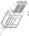
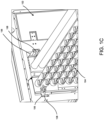
FIGs. 1A to 1C show views of a system for enabling the installation and maintenance of furnace assembly in a rooftop unit (RTU). -
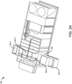
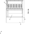
FIGs. 2A to 2C shows views of a system for enabling the installation and maintenance of power exhaust component in a rooftop unit (RTU). -
FIG. 2D shows a view of a movable/hinged portion of the casing of the power exhausts to provide access to the interior of the power exhaust. -
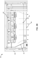
FIGs. 3A and3B shows views of an air-directing baffle configured upstream of an electric heater in a rooftop unit (RTU) to direct air toward limit switches and heating elements associated with the electric heater. -
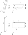
FIGs. 4A to 4D shows views of a first embodiment of the air-directing baffle ofFIGs. 3A and3B . - FIGs. SAto 5D shows views of a second embodiment of the air-directing baffle of
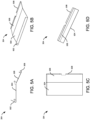
FIGs. 3A and3B . - The following is a detailed description of embodiments of the invention depicted in the accompanying drawings. The embodiments are in such detail as to clearly communicate the invention. However, the amount of detail offered is not intended to limit the anticipated variations of embodiments; on the contrary, the intention is to cover all modifications and alternatives falling within the scope of the invention as set out in the appended claims.
- Various terms are used herein. To the extent a term used in a claim is not defined below, it should be given the broadest definition persons in the pertinent art have given that term as reflected in printed publications and issued patents at the time of filing.
- In the specification, reference may be made to the spatial relationships between various components and to the spatial orientation of various aspects of components as the devices are depicted in the attached drawings. However, as will be recognized by those skilled in the art after a complete reading of the disclosure, the components of this invention. described herein may be positioned in any desired orientation. Thus, the use of terms such as "above," "below," "upper," "lower," "first", "second" or other like terms to describe a spatial relationship between various components or to describe the spatial orientation of aspects of such components should be understood to describe a relative relationship between the components or a spatial orientation of aspects of such components, respectively, described herein may be oriented in any desired direction.
- A rooftop unit (RTU) may include a furnace assembly installed inside the RTU for heating the air circulated by the RTU. The heated air may then be supplied to a space of a building where the RTU is installed. The RTU may further include one or more power exhaust components which facilitate the ventilation and discharge of air from the RTU and the space. Power exhaust components may be configured to remove exhaust gases, fumes, and odors generated by the combustion process in the furnace assembly and also from the space, thereby providing proper air circulation and maintaining a healthy indoor environment. However, these furnace assemblies and power exhaust components are heavy and bulky. The size and weight make maintenance, service and installation difficult. In addition, as the power exhaust components typically extend out of the RTU's housing, this may make the RTU difficult to ship and install at desired locations, and the power exhaust components may also get damaged while shipping or transporting.
- There is, therefore, a need to improve access to the furnace assembly for maintenance by allowing easier movement of the furnace assembly out of the RTU's housing. Further, there is also a need to improve the shipping and installation of the power exhaust components of the RTU by protecting the power exhaust components during shipping and simplifying installation.
- In addition, the RTU may include also an electric heater for heating operations. The electric heater may include limit switches to prevent overheating and potential hazards by automatically shutting off the heater if it exceeds a certain temperature threshold. However, limit switches may falsely trip when they fail to receive proper airflow. There is, therefore, a need to direct airflow towards the limit switches to prevent nuisance tripping of the limit switches while preventing any air recirculation in the RTU and further ensuring the consistent flow of air through the heating elements of the electric heater.
- Disclosed herein is an RTU which addresses the above concerns. The RTU includes a sliding mechanism, disposed between two opposing walls of the RTU housing, which support the furnace assembly and facilitates access to the furnace assembly for maintenance and service. The RTU further includes a sliding mechanism, disposed between two opposing walls of the RTU housing, which allows the power exhaust component(s) to be stowed within the RTU housing during shipping and installed in an unpacked position. Further, the invention also provides an air-directing baffle for the electric heater of the RTU, which directs airflow towards the limit switches to prevent nuisance tripping of the limit switches while preventing any air recirculation in the RTU and further ensuring smooth flow of air through the heating elements of the electric heater.
- Referring to
FIGs. 1A to 1C , asystem 100 for enabling installation and maintenance of one or more furnace assemblies 104 (collectively referred to asfurnace assemblies 104 and individually referred to asfurnace assembly 104, herein) in a rooftop unit (RTU) is disclosed. The RTU may include a housing 102 (or an enclosure) having one or more sections defined by one or more walls 102-1 to 102-3 to accommodate and support thefurnace assembly 104 and one or more other components associated with the RTU. Thesystem 100 may include a sliding mechanism configured between the opposing (interior) wall(s) of thehousing 102 of the RTU and thefurnace assembly 104 to be installed within the RTU. The sliding mechanism may be installed in the section (of the housing) dedicated to thefurnace assemblies 104, where an opening or window 102-4 may be provided to provide access to the corresponding section and movement of thefurnace assembly 104 into or out of the RTU. The opening 102-4 may further be configured to be closed by a removable panel (not shown). - The sliding mechanism may be configured to support the
furnace assemblies 104 and further enable movement of thefurnace assembly 104 between a stowed position (also referred to as installed position) as shown inFIGs. 1B and1C , and an unpacked position (also referred to as maintenance position) as shown inFIG. 1A . In the stowed position, as shown inFIGs. 1B and1C , the correspondingfurnace assembly 104 may remain disposed of within the RTU during operation or while transporting. Further, in the unpacked position, as shown inFIG. 1A , the correspondingfurnace assembly 104 may remain at least partially outside thehousing 102 so that the correspondingfurnace assembly 104 may be accessed and/or removed from the RTU for maintenance by one or more users. - In one or more embodiments, the sliding mechanism includes two or
more guide rails 106 disposed on opposing interior wall(s) of thehousing 102 in the section dedicated to thefurnace assemblies 104. Further, the sliding mechanism may include two ormore rollers 108 disposed at predefined positions on thefurnace assembly 104. Therollers 108 movably engage with the guide rails to support thefurnace assembly 104 and enable movement of thefurnace assembly 104 between the stowed position and the unpacked position with respect to the RTU. - In one or more embodiments, as shown in
FIGs. 1A to 1C , therollers 108 may be disposed at the top end of thefurnace assembly 104 as shown inFIG. 1C and theguide rails 106 may be disposed on the two opposing vertical interior walls 102-1, 102-2 of the housing 102 (as used herein "disposed on opposing interior walls" includes instances in which the guide rails extend parallel to the two opposite vertical interior walls 102-1, 102-2) as shown inFIG. 1A and1B such that thefurnace assembly 104 remains disposed between the opposite vertical walls 102-1, 102-2 when in the stowed position. The opposite vertical walls 102-1, 102-2 may extend between a window or opening end 102-4 of the housing (section) and another vertical wall 102-3 opposite the window end (also designated as 102-4, herein). Further, therollers 108 may extend on two opposite sides of the top end of thefurnace assembly 104. Further, theguide rails 106 may extend parallel to the opposite vertical walls 102-1, 102-2 on two opposite sides of the furnace assembly 104 (with or without any attachment with the opposite vertical walls 102-1, 102-2) such that thefurnace assembly 104 remain disposed between theguide rails 106 or the opposite vertical walls 102-1, 102-2 when in the stowed position. Further, in one or more embodiments, theguide rails 106 may extend between the window/opening end 102-4 and the vertical wall 102-3 opposite the window end 102-4 through a frame or support structure. Furthermore, therollers 108 may also be configured at the top end, the bottom end, or a portion between the top and bottom end of the furnace assembly104, on a side opposite the window end 104-4 of thehousing 102. - In one or more embodiments (not shown), the
rollers 108 may be configured at the bottom end of thefurnace assembly 104 and theguide rails 106 may be configured within thehousing 102 such that at least one of theguide rails 106 remains below and movably engaged with therollers 108. For instance, when the RTU involves a single furnace assembly, therollers 108 may be disposed at the bottom end of thefurnace assembly 104 and theguide rails 106 may be disposed over or parallel to the bottom base of thehousing 102, with theguide rails 106 being movably engaged with therollers 108. Further, when the RTU involvesmultiple furnace assemblies 104, therollers 108 may be configured at the bottom end of the bottom-most furnace assembly with the other furnace assemblies stacked over the bottom-most furnace assembly and theguide rails 106 may be disposed over or at the bottom base of thehousing 102, such that theguide rails 106 remains movably engaged with therollers 108 of the bottom-most furnace assembly. - In one or more embodiments (not shown), the sliding mechanism may include the
rollers 108 disposed at predefined positions on opposing interior wall(s) of thehousing 102 or predefined positions on a frame extending parallel to the interior walls. Further, theguide rails 106 may be configured with each of thefurnace assemblies 104. Therollers 108 movably engage with theguide rails 106 to support thefurnace assemblies 104 and further enable movement of thefurnace assembly 104 between the stowed position and the unpacked position. For instance, in one or more embodiments, theguide rails 106 may extend along opposite sides or faces of thegas furnace assembly 104 and therollers 108 may be configured on the two opposite vertical walls 102-1, 102-2 of thehousing 102 or the frame extending parallel to the vertical walls 102-1, 102-2, such that theguide rails 106 remain movably engaged with therollers 108 to allow movement of thefurnace assembly 104 between the stowed position, and the unpacked position. Further, in one or more embodiments, theguide rails 106 may extend along the bottom and top faces of thefurnace assembly 104 and therollers 108 may be configured on the bottom base and top wall of thehousing 102 or the frame extending parallel to the bottom base and top wall, such that theguide rails 106 remain movably engaged with therollers 108 to allow movement of thefurnace assembly 104 between the stowed position, and the unpacked position - Thus, the
system 100 may allow easier and quick removal or movement of thefurnace assembly 104 in or out of the RTU'shousing 102 during the service and maintenance operations. This reduces the time, effort, and cost of service and further makes it easy to replace thefurnace assembly 104 from the RTU. In addition, this allows thefurnace assemblies 104 to be transported separately and later on installed in the RTU at the installation site with reduced effort. - Referring to
FIGs. 2A to 2D , asystem 200 for enabling installation and maintenance of two or more power exhaust components 204-1, 204-2 (collectively referred to as power exhaust 204) in a rooftop unit (RTU) is disclosed. The RTU may include a housing 202 (or an enclosure) having one or more sections 202-A, 202-B defined by one or more walls to accommodate and support the power exhaust components 204-1, 204-2 associated with the RTU. Thesystem 200 may include a sliding mechanism configured between the opposing (interior) wall(s) of the housing of the RTU and the power exhaust components 204-1, 204-2. The sliding mechanism may be installed in the section (of the housing) 202-A, 202-B dedicated to the power exhaust components 204-1, 204-2, where an opening or window may be provided to provide access to the corresponding section 202-A, 202-B and movement of the power exhaust components 204-1, 204-2 into or out of the RTU. - In one or more embodiments, as shown in
FIGs. 2A to 2C , the sections 202-A, 202-B and corresponding window/opening may be provided on two opposite sides of thehousing 202 to accommodate two power exhaust components 204-1, 204-2 on the opposite sides of the RTU, where the two sections 202-A, 202-B may or may not be separated by a common wall, however, the number and positions of thepower exhaust 204 and the dedicated section 202-A, 202-B and window in the RTU may vary depending on the capacity of the RTU without any limitation. - The sliding mechanism may be configured to support the power exhaust components 204-1, 204-2 and enable movement of the power exhaust components 204-1, 204-2 between a stowed position (also referred to as transportation position) as shown in
FIG. 2B , and an unpacked position (also referred to as the installed position or maintenance position) as shown inFIGs. 2A and2C . In the stowed position, as shown inFIG. 2B , the power exhaust components 204-1, 204-2 may remain disposed of within the sections 202-A, 202-B while transporting, thereby avoiding any damage to the power exhausts 204-1, 204-2. Further, in the unpacked position, as shown inFIG. 2A and2C , the power exhaust component 204-1, 204-2 may remain at least partially outside the housing (sections 202-A, 202-B) so that the corresponding power exhaust component 204-1, 204-2 may operate and further be accessed and/or removed from the RTU for maintenance by one or more users. - In one or more embodiments, as shown in
FIG. 2D , at least a portion of acasing 208 associated with each of the power exhaust components 204-1, 204-2 may be adapted to be removed or moved to provide access to the interior of the power exhaust component 204-1, 204-2 once the power exhaust component 204-1, 204-2 is in the unpacked position. Further, in one or more embodiments, at least a portion 208-1 of acasing 208 associated with each of the power exhaust component 204-1, 204-2 may be hingedly coupled to the remainingportion 210 of power exhaust component 204-1, 204-2 to provide access to an interior (motor, fan propeller, and the like) of the corresponding power exhaust component 204-1, 204-2 once the power exhaust components 204-1, 204-2 are in the unpacked position. As shown inFIG. 2D , a bottom end 208-1 of thecasing 208 may be removably (or hingedly) coupled to abase 210 of the power exhaust 204-1, 204-2, such that thecasing 208 may be tilted downward once the power exhaust component 204-1, 204-2 is at least partially outside the sections 202-A, 202-B of the housing in the unpacked position. This may provide access to the interior of the power exhaust component 204-1, 204-2 from the top. However, any other end of the movable portion of thecasing 208 may also be hingedly or removably coupled to therest portion 210 of the power exhaust component 204-1, 204-2 without any limitation. - Referring back to
FIGs. 2A to 2C , in one or more embodiments, the sliding mechanism may include two ormore guide rails 206 disposed on opposing interior wall(s) of the housing in the sections dedicated to the power exhausts 204-1, 204-2. Further, the sliding mechanism may include two or more rollers (not shown) disposed at predefined positions on the power exhausts 204-1, 204-2. The rollers movably engage with theguide rails 206 to support the power exhaust component 204-1, 204-2 and enable movement of the power exhaust component 204-1, 204-2 between the stowed position and the unpacked position with respect to the RTU in their respective sections 202-A, 202-B. - In one or more embodiments, the rollers may be disposed on extreme sides at a bottom end and/or a top end of the corresponding power exhaust component 204-1, 204-2. Further, the
guide rails 206 may be disposed on a bottom base 202-1 and/or a top wall 202-2 of the dedicated section 202-A, 202-B of the housing. Disposed on includes extending parallel to the bottom base 202-1 and/or the top wall 202-2 such that the power exhaust components 204-1, 204-2 remain disposed between the bottom base 202-1 and the top wall 202-2 of their respective section when in the stowed position. Further, in one or more embodiments, the rollers may be configured on extreme sides at a bottom end and/or a top end of the corresponding power exhaust component 204-1, 204-2. Further, theguide rails 206 may be disposed on two opposing vertical walls (not shown) of the dedicated section 202-A, 202-B or may extend parallel to the two opposing vertical walls such that the power exhaust components 204-1, 204-2 remain disposed between the opposite vertical walls of their respective sections 202-A, 202-B when in the stowed position - The opposing vertical walls, or the bottom base 202-1 and top wall 202-2 of the housing may extend between the two window/opening ends of the housing with or without the common separation wall between the two sections 202-A, 202-B. The rollers may extend on the extreme sides at the bottom end and/or the top end of the power exhausts 204-1, 204-2. Further, the
guide rails 206 may extend parallel to the bottom base 202-1 and/or the top wall 202-2 (with or without any attachment to the bottom base and/or the top wall) such that the power exhausts 204-1, 204-2 remain movably engaged with the guide rails 206. Further, in one or more embodiments, theguide rails 206 may extend between the window end of the housing and the vertical wall opposite the window end through a frame or support structure. Furthermore, the rollers may be configured at the top end, bottom end, or a portion between the top and bottom end of the power exhausts 204-1, 204-2, on the common separation wall side of the housing. - In one or more embodiments (not shown), the sliding mechanism may include the rollers disposed at predefined positions on the interior wall(s) of the housing or predefined positions on a frame extending parallel to the interior walls. Further, the
guide rails 206 may be disposed on the power exhaust component 204-1, 204-2. The rollers movably engage with theguide rails 206 to support the power exhaust component 204-1, 204-2 and enable movement of the power exhaust components 204-1, 204-2 between the stowed position and the unpacked position. For instance, in one or more embodiments, theguide rails 206 may extend along opposite lateral sides or faces of the power exhaust component204-1, 204-2 and the rollers may be configured on the two opposite vertical walls of the housing or the frame extending parallel to the interior walls, such that theguide rails 206 remain movably engaged with the rollers to allow movement of the power exhaust component 204-1, 204-2 between the stowed position, and the unpacked position. Further, in one or more embodiments, theguide rails 206 may extend along the top face or bottom face of the power exhaust 204-1, 204-2 and the rollers may be disposed on the top wall or the bottom base of the housing or the frame extending parallel to the top wall 202-2 or bottom base 202-1, such that theguide rails 206 movably engaged with the rollers to allow movement of the power exhausts 204-1, 204-2 between the stowed position, and the unpacked position - Thus, the
system 200 may allow easy and quick removal or movement of the power exhaust component 204-1, 204-2 in or out of the RTU's housing. Retaining the power exhaust inside the RTU during shipping keeps the power exhaust components 204-1, 204-2 safe. - Referring to
FIGs. 3A and3B , an air-directingbaffle 304 for directing consistent airflow towards limit switches and heating elements associated with anelectric heater 302 of a rooftop unit (RTU) is disclosed. The RTU may include a housing 306 (or an enclosure) having one or more sections defined by one or more walls to accommodate and support theelectric heater 302, and one ormore fans 308 upstream of theelectric heater 302 with aspace 310 therebetween. Thefans 308 may enable the flow of air through theelectric heater 302 and further facilitate the supply of heated or conditioned air in aspace 310 where the RTU is installed. Theelectric heater 302 may include multiple heating elements that upon actuation may control or adjust the heating capacity of theelectric heater 302. Theelectric heater 302 may further be configured with limit switches (not shown) in thermal contact with the heating elements, which may prevent overheating and potential hazards by automatically shutting off theheater 302 if it exceeds a certain temperature threshold. - The
baffle 304 may be a member of a predefined shape and dimension defining shape of thebaffle 304, which may be removably or fixedly configured to an interior wall of the RTU'shousing 306 and oriented vertically between theelectric heater 302 and thefans 308, such that thebaffle 304 may direct the flow of air towards the limit switches and/or heating elements associated with theelectric heater 302 while restricting recirculation of the air towards thefans 308 or within the RTU. Thus, thebaffle 304 directs airflow towards the limit switches to prevent nuisance tripping of the limit switches while preventing any air recirculation in the RTU and further ensuring the consistent flow of air through the heating elements of theelectric heater 302. - It may be obvious to a person skilled in the art that the shapes and dimensions of the
overall baffle 304, the corresponding different sections of thebaffle 304, and their orientation angles may be selected based on theavailable space 310 between thefans 308 and theelectric heater 302 in the RTU, such that thebaffle 304 may direct airflow towards the limit switches to prevent nuisance tripping of the limit switches while preventing any air recirculation in the RTU and further ensuring the consistent flow of air through the heating elements of theelectric heater 302. - In one or more embodiments, the baffle 304 (or member) may include a first section of a first shape and dimension having a first end and a second end. The first section may be configured to be coupled to an interior wall between the
electric heater 302 andfans 308 such that the member is oriented vertically between theelectric heater 302 and thefans 308. Thebaffle 304 may further include a second section of a second shape and dimension extending at a first predetermined angle from the second end of the first section, such that a first end of the second section is connected to the second end of the first section. Further, thebaffle 304 may include a third section of a third shape and dimension extending at a second predetermined angle from a second end, opposite to the first end, of the second section, such that the first end of the third section is connected to the second end of the second section. - In one or more embodiments, as shown in
FIG. 4A to 4D , the baffle 304 (or member) may include afirst section 402 of a first shape and dimension having a first end and a second end. Thefirst section 402 may be configured to be coupled to an interior wall between theelectric heater 302 andfans 308 such that thebaffle 304 is oriented vertically between theelectric heater 302 and thefans 308. Thebaffle 304 may further include asecond section 404 of a second shape and dimension extending at a first angle (A) of 105 to 150 degrees from the second end of thefirst section 402, such that a first end of thesecond section 404 is connected to the second end of thefirst section 402. Further, thebaffle 304 may include athird section 406 of a third shape and dimension extending at a second angle (B) of 30 to 75 degrees from a second end, opposite to the first end, of thesecond section 404, such that the first end of thethird section 406 is connected to the second end of thesecond section 404. - In one or more embodiments, as shown in
FIG. 5A to 5D , thebaffle 304 or member may include afirst section 502 of a first shape and dimension having a first end and a second end. Thefirst section 502 may be configured to be coupled to an interior wall between theelectric heater 302 andfans 308 such that thebaffle 302 is oriented vertically between theelectric heater 302 and thefans 308. Thebaffle 304 may further include asecond section 504 of a second shape and dimension extending at a first angle (C) of 30 to 75 degrees from the second end of thefirst section 502, such that a first end of the second section is connected to the second end of the first section. Further, thebaffle 304 may include athird section 506 of a third shape and dimension extending at a second angle (D) of 190 to 240 degrees from a second end, opposite to the first end, of thesecond section 504, such that the first end of thethird section 506 is connected to the second end of thesecond section 504. Furthermore, thebaffle 304 may include afourth section 508 of a fourth shape and dimension extending from a second end, opposite to the first end, of thethird section 506, such that the first end of thefourth section 508 is connected to the second end of thethird section 506, wherein thefourth section 508 makes a third angle (E) of 75 to 120 degrees from a third axis extending along a length of thethird section 506. - In one or more embodiments, the first section, the second section, the third section, and/or the further section of the
baffle 304 ofFIGs. 3A to 5D may be different flat members that may be cut-out individually from one or more sheets of predefined material(s) in their respective shape and dimension. These cut-outs may be further coupled together at the respective predetermined angles to form asingle baffle 304 having the predefined shape and dimension as shown inFIGs 4A to 5D . - Alternatively, in one or more embodiments, a single sheet of a predefined material may be machined to form the
baffle 304 having the predefined shape and dimension, with the first section, the second section, the third section, and/or the further section having their respective shape and dimension and oriented at their respective angles. - In one or more embodiments, the first section may include one or more coupling elements to facilitate the coupling of the
baffle 304 to the interior wall of the RTU. In one or more embodiments, the coupling elements may be a flat member or a curved member, with or without cut-outs, extending from any of the first section, the second section, the third section, and/or the further section of thebaffle 304. The coupling elements may further include one or more threaded grooves configured to facilitate removable coupling of thebaffle 304 to the interior wall of the RTU using one or more fasteners. However, thebaffle 304 may also be welded or fixedly coupled to the interior wall of the RTU using one or more known techniques available in the art. - Thus, this invention provides a system (100) for enabling the installation and maintenance of furnace assembly in a rooftop unit (RTU), which allows easier and quick removal or movement of the furnace assembly out of the RTU's housing while shipping the RTU as well as during the service and maintenance operations of the furnace once installed. The invention further provides a system (200) for enabling the installation and maintenance of power exhausts in the RTU, which allows storage of the power exhaust within the RTU's housing while shipping the RTU to keep the power exhausts safe and further allows removal of the power exhausts from the RTU's housing during installation. Further, the invention also provides an air-directing baffle (304) for the electric heater of the RTU, which directs airflow towards the limit switches to prevent nuisance tripping of the limit switches while limiting or preventing any air recirculation in the RTU and further ensuring consistent flow of air through the heating elements of the electric heater.
- While the invention has been described with reference to exemplary embodiments, it will be understood by those skilled in the art that various changes may be made without departing from the scope of the invention as set out in the appended claims. Modifications may be made to adopt a particular situation or material to the teachings of the invention without departing from the scope thereof. Therefore, it is intended that the invention not be limited to the particular embodiment disclosed, but that the invention includes all embodiments falling within the scope of the invention as set out in the appended claims.
- In interpreting the specification, all terms should be interpreted in the broadest possible manner consistent with the context. In particular, the terms "comprises" and "comprising" should be interpreted as referring to elements, components, or steps in a non-exclusive manner, indicating that the referenced elements, components, or steps may be present, or utilized, or combined with other elements, components, or steps that are not expressly referenced. Where the specification claims refer to at least one of something selected from the group consisting of A, B, C ....and N, the text should be interpreted as requiring only one element from the group, not A plus N, or B plus N, etc.
Claims (15)
- A rooftop unit (RTU) having a furnace assembly (104), the RTU comprising:
a sliding mechanism configured between opposing one or more interior walls of a housing of the RTU (102), wherein the sliding mechanism is configured to support the furnace assembly and enable movement of the furnace assembly between a stowed position, and an unpacked position. - The RTU of claim 1, wherein in the stowed position, the corresponding furnace assembly (104) is disposed within the RTU housing (102), and wherein in the unpacked position, the corresponding furnace assembly is at least partially outside the housing.
- The RTU of claim 1 or 2, wherein the sliding mechanism comprises:two or more guide rails (106) disposed on the opposing interior walls (102-1, 102-2) of the housing (102); andtwo or more rollers (108) configured at predefined positions on the furnace assembly (104), wherein the rollers movably engage with the guide rails to support the furnace assembly and enable movement of the furnace assembly between the stowed position and the unpacked position.
- The RTU of claim 3, wherein the two or more rollers (108) are disposed at a top end of the furnace assembly (104), and the two or more guide rails (106) are disposed on opposing vertical interior walls (102-1, 102-2) of the housing (102) such that the furnace assembly remains disposed between the opposing vertical interior walls when in the stowed position; and/or
wherein the two or more rollers (108) are configured at a bottom end of the furnace assembly (104), and wherein the guide rails (106) are disposed within the housing such that the guide rails remain below and movably engaged with the rollers. - The RTU of claim 1, wherein the sliding mechanism comprises:two or more rollers (108) disposed at predefined positions on the opposing interior walls (102-1, 102-2) of the housing (102); andtwo or more guide rails (106) disposed on the furnace assembly (104), wherein the rollers are adapted to movably engage with the guide rails to support the furnace assembly and enable movement of the furnace assembly between the stowed position and the unpacked position.
- A rooftop unit (RTU) having a power exhaust component (204), the RTU comprising:
a sliding mechanism configured between opposing interior walls of a housing (202) of the RTU and a power exhaust component, wherein the sliding mechanism is configured to support the power exhaust component and enable movement of the power exhaust component between a stowed position, and an unpacked position. - The RTU of claim 6, wherein the housing (202) comprises an opening or window to facilitate movement of the power exhaust component (204) between the stowed position, and the unpacked position.
- The RTU of claim 6 or 7, wherein at least a portion of a casing (208) associated with the power exhaust component (204) is configured to provide access to an interior of the power exhaust component (204-1), optionally
wherein at least a portion of a casing (208) associated with the power exhaust component (204) is hingedly coupled to the casing to provide access to an interior of the power exhaust component (204-1). - The RTU of claim 6, 7 or 8, wherein in the stowed position, the corresponding power exhaust component (204) is within the RTU housing (202), and wherein in the unpacked position, the power exhaust component is at least partially outside the housing.
- The RTU of any of claims 6 to 9, wherein the sliding mechanism comprises:two or more guide rails (206) disposed on the interior walls of the housing; andtwo or more rollers disposed at predefined positions on the power exhaust component (204), wherein the rollers are adapted to movably engage with the guide rails to support the power exhaust component and enable movement of the power exhaust component between the stowed position and the unpacked position; optionallywherein the guide rails (206) are configured at a bottom base (202-1) and/or a top wall (202-2) of the housing (202) and the rollers are disposed at a bottom end and/or a top end of the power exhaust component, such that the rollers movably engage with the guide rails.
- The RTU of claim 6, wherein the sliding mechanism comprises:two or more rollers disposed at predefined positions on the interior walls of the housing; andtwo or more guide rails (206) disposed on the power exhaust component (204), wherein the two or more rollers movably engage with the guide rails to support the power exhaust component and enable movement of the power exhaust component between the stowed position and the unpacked position; optionally
the rollers are configured at a bottom base (202-1) and/or a top wall (202-2) of the housing (202); andthe guide rails (206) are configured at a bottom end and/or a top end of each of the power exhaust component (204), wherein the guide rails movably engage with the rollers to support the power exhaust component and enable movement of the power exhaust component between the stowed position and the unpacked position. - An air-directing baffle (304) for an electric heater (302) associated with a rooftop unit (RTU), the baffle comprising:a member of a predefined shape defining shape of the baffle, wherein the baffle is configured to be removably configured to an interior wall of the RTU between the electric heater and one or more fans (308) associated with the RTU, andwherein the baffle is configured to direct flow of air towards a limit switch and/or heating elements associated with the electric heater while restricting recirculation of the air towards the one or more fans or within the RTU.
- The baffle (304) of claim 12, wherein the baffle comprises:a first section of a first length having a first end and a second end, wherein the first section is configured to be coupled to an interior wall between the electric heater (302) and one or more fans (308) such that the member is oriented vertically between the electric heater and the one or more fans;a second section of a second length extending at a first predetermined angle from the second end of the first section, such that a first end of the second section is connected to the second end of the first section; anda third section of a third length extending at a second predetermined angle from a second end, opposite to the first end, of the second section, such that the first end of the third section is connected to the second end of the second section.
- The baffle (304) of claim 12 or 13, wherein the baffle comprises:a first section (402) of a first shape and dimension having a first end and a second end, wherein the first section is configured to be coupled to an interior wall between the electric heater (302) and one or more fans (308) such that the member is oriented vertically between the electric heater and the one or more fans;a second section (404) of a second shape and dimension extending from the second end of the first section, such that a first end of the second section is connected to the second end of the first section, wherein the second section makes a first angle of 30 to 75 degrees from a first axis extending along a length of the first section; anda third section (406) of a third shape and dimension extending from a second end, opposite to the first end, of the second section, such that the first end of the third section is connected to the second end of the second section, wherein the third section makes a second angle of 275 to 350 degrees from a second axis extending along a length of the second section, optionallywherein the the third section makes a second angle of 190 to 240 degrees from a second axis extending along a length of the second section, and wherein the baffle comprisesa fourth section (508) of a fourth shape and dimension extending from a second end, opposite to the first end, of the third section, such that the first end of the fourth section is connected to the second end of the third section, wherein the fourth section makes a third angle (E) of 75 to 120 degrees from a third axis extending along a length of the third section.
- The baffle of claim 13 or 14, wherein the first section (402) comprises one or more coupling elements to facilitate coupling of the baffle to the interior wall of the RTU.
Applications Claiming Priority (1)
| Application Number | Priority Date | Filing Date | Title |
|---|---|---|---|
| US202363505095P | 2023-05-31 | 2023-05-31 |
Publications (2)
| Publication Number | Publication Date |
|---|---|
| EP4471351A2 true EP4471351A2 (en) | 2024-12-04 |
| EP4471351A3 EP4471351A3 (en) | 2024-12-18 |
Family
ID=91249006
Family Applications (1)
| Application Number | Title | Priority Date | Filing Date |
|---|---|---|---|
| EP24177749.9A Pending EP4471351A3 (en) | 2023-05-31 | 2024-05-23 | Rooftop hvac unit |
Country Status (3)
| Country | Link |
|---|---|
| US (1) | US20240401843A1 (en) |
| EP (1) | EP4471351A3 (en) |
| CN (1) | CN119063100A (en) |
Family Cites Families (3)
| Publication number | Priority date | Publication date | Assignee | Title |
|---|---|---|---|---|
| US4139052A (en) * | 1977-11-23 | 1979-02-13 | Westinghouse Electric Corp. | Roof top air conditioning unit |
| US11353224B2 (en) * | 2019-11-26 | 2022-06-07 | Captive-Aire Systems, Inc. | Rooftop exhaust system with automatic motor lockout |
| CN116086014A (en) * | 2021-11-05 | 2023-05-09 | 特灵空调系统(中国)有限公司 | Air handling unit with box-type air deflector and method for disassembling combustion heater therein |
-
2024
- 2024-05-22 US US18/671,041 patent/US20240401843A1/en active Pending
- 2024-05-23 EP EP24177749.9A patent/EP4471351A3/en active Pending
- 2024-05-30 CN CN202410685427.3A patent/CN119063100A/en active Pending
Also Published As
| Publication number | Publication date |
|---|---|
| EP4471351A3 (en) | 2024-12-18 |
| US20240401843A1 (en) | 2024-12-05 |
| CN119063100A (en) | 2024-12-03 |
Similar Documents
| Publication | Publication Date | Title |
|---|---|---|
| US4813475A (en) | Temperature control means for a self service banking system | |
| US4748825A (en) | Bus air conditioning unit | |
| EP2391198B1 (en) | Air cooling of medium voltage drive components | |
| US20120329378A1 (en) | Assembly for Extracting Heat from a Housing for Electronic Equipment | |
| US20080188175A1 (en) | Air circulator with releasable air grille | |
| AU2013100158A4 (en) | Apparatus for Exhausting Air | |
| US6501650B2 (en) | Series-parallel fans system | |
| US6524181B2 (en) | Garage venting device | |
| JPS621180B2 (en) | ||
| US5619864A (en) | Compact heat pump | |
| US20240401843A1 (en) | Rooftop hvac unit | |
| US20250301597A1 (en) | Heat Dissipation Structure for Induction Hobs and Induction Hob | |
| WO2020163939A1 (en) | Transportable datacenter | |
| US4134545A (en) | Apparatus for recirculating heated air | |
| JP5268855B2 (en) | Rack and information processing equipment accommodation | |
| JP2823515B2 (en) | Ductless type outside air introduction air conditioning system | |
| CN210565221U (en) | Portable Ventilator | |
| JP2007322049A (en) | Replacement ventilation system for electrical room | |
| CN101376477A (en) | Control disk system for elevator | |
| JP2008128538A (en) | Cooling method for heat generation equipment and cooling device | |
| US20100075589A1 (en) | Angled blower deck apparatus and method | |
| JPH07101781B2 (en) | Cabinet cooling structure | |
| JP4294461B2 (en) | Air conditioning equipment | |
| US20120279248A1 (en) | Turbo Coil Refrigeration System | |
| CN215071785U (en) | UPS power supply |
Legal Events
| Date | Code | Title | Description |
|---|---|---|---|
| PUAI | Public reference made under article 153(3) epc to a published international application that has entered the european phase |
Free format text: ORIGINAL CODE: 0009012 |
|
| STAA | Information on the status of an ep patent application or granted ep patent |
Free format text: STATUS: THE APPLICATION HAS BEEN PUBLISHED |
|
| PUAL | Search report despatched |
Free format text: ORIGINAL CODE: 0009013 |
|
| AK | Designated contracting states |
Kind code of ref document: A2 Designated state(s): AL AT BE BG CH CY CZ DE DK EE ES FI FR GB GR HR HU IE IS IT LI LT LU LV MC ME MK MT NL NO PL PT RO RS SE SI SK SM TR |
|
| AK | Designated contracting states |
Kind code of ref document: A3 Designated state(s): AL AT BE BG CH CY CZ DE DK EE ES FI FR GB GR HR HU IE IS IT LI LT LU LV MC ME MK MT NL NO PL PT RO RS SE SI SK SM TR |
|
| RIC1 | Information provided on ipc code assigned before grant |
Ipc: F24D 5/02 20060101ALI20241108BHEP Ipc: F24H 9/00 20220101ALI20241108BHEP Ipc: F24H 3/06 20220101ALI20241108BHEP Ipc: F24F 1/44 20110101ALI20241108BHEP Ipc: F24F 1/56 20110101ALI20241108BHEP Ipc: F24H 9/02 20060101AFI20241108BHEP |
|
| STAA | Information on the status of an ep patent application or granted ep patent |
Free format text: STATUS: REQUEST FOR EXAMINATION WAS MADE |
|
| 17P | Request for examination filed |
Effective date: 20250616 |