EP4471298A1 - Straddled vehicle equipped with parallel multicylinder engine - Google Patents
Straddled vehicle equipped with parallel multicylinder engine Download PDFInfo
- Publication number
- EP4471298A1 EP4471298A1 EP24178285.3A EP24178285A EP4471298A1 EP 4471298 A1 EP4471298 A1 EP 4471298A1 EP 24178285 A EP24178285 A EP 24178285A EP 4471298 A1 EP4471298 A1 EP 4471298A1
- Authority
- EP
- European Patent Office
- Prior art keywords
- clutch
- actuator
- shift
- vehicle
- crankcase
- Prior art date
- Legal status (The legal status is an assumption and is not a legal conclusion. Google has not performed a legal analysis and makes no representation as to the accuracy of the status listed.)
- Pending
Links
Images




Classifications
-
- F—MECHANICAL ENGINEERING; LIGHTING; HEATING; WEAPONS; BLASTING
- F16—ENGINEERING ELEMENTS AND UNITS; GENERAL MEASURES FOR PRODUCING AND MAINTAINING EFFECTIVE FUNCTIONING OF MACHINES OR INSTALLATIONS; THERMAL INSULATION IN GENERAL
- F16H—GEARING
- F16H63/00—Control outputs from the control unit to change-speed- or reversing-gearings for conveying rotary motion or to other devices than the final output mechanism
- F16H63/02—Final output mechanisms therefor; Actuating means for the final output mechanisms
- F16H63/08—Multiple final output mechanisms being moved by a single common final actuating mechanism
- F16H63/16—Multiple final output mechanisms being moved by a single common final actuating mechanism the final output mechanisms being successively actuated by progressive movement of the final actuating mechanism
- F16H63/18—Multiple final output mechanisms being moved by a single common final actuating mechanism the final output mechanisms being successively actuated by progressive movement of the final actuating mechanism the final actuating mechanism comprising cams
-
- F—MECHANICAL ENGINEERING; LIGHTING; HEATING; WEAPONS; BLASTING
- F16—ENGINEERING ELEMENTS AND UNITS; GENERAL MEASURES FOR PRODUCING AND MAINTAINING EFFECTIVE FUNCTIONING OF MACHINES OR INSTALLATIONS; THERMAL INSULATION IN GENERAL
- F16H—GEARING
- F16H61/00—Control functions within control units of change-speed- or reversing-gearings for conveying rotary motion ; Control of exclusively fluid gearing, friction gearing, gearings with endless flexible members or other particular types of gearing
- F16H61/26—Generation or transmission of movements for final actuating mechanisms
- F16H61/28—Generation or transmission of movements for final actuating mechanisms with at least one movement of the final actuating mechanism being caused by a non-mechanical force, e.g. power-assisted
- F16H61/32—Electric motors , actuators or related electrical control means therefor
-
- F—MECHANICAL ENGINEERING; LIGHTING; HEATING; WEAPONS; BLASTING
- F16—ENGINEERING ELEMENTS AND UNITS; GENERAL MEASURES FOR PRODUCING AND MAINTAINING EFFECTIVE FUNCTIONING OF MACHINES OR INSTALLATIONS; THERMAL INSULATION IN GENERAL
- F16H—GEARING
- F16H63/00—Control outputs from the control unit to change-speed- or reversing-gearings for conveying rotary motion or to other devices than the final output mechanism
- F16H63/02—Final output mechanisms therefor; Actuating means for the final output mechanisms
- F16H63/30—Constructional features of the final output mechanisms
- F16H63/304—Constructional features of the final output mechanisms the final output mechanisms comprising elements moved by electrical or magnetic force
-
- B—PERFORMING OPERATIONS; TRANSPORTING
- B60—VEHICLES IN GENERAL
- B60Y—INDEXING SCHEME RELATING TO ASPECTS CROSS-CUTTING VEHICLE TECHNOLOGY
- B60Y2200/00—Type of vehicle
- B60Y2200/10—Road Vehicles
- B60Y2200/12—Motorcycles, Trikes; Quads; Scooters
-
- F—MECHANICAL ENGINEERING; LIGHTING; HEATING; WEAPONS; BLASTING
- F16—ENGINEERING ELEMENTS AND UNITS; GENERAL MEASURES FOR PRODUCING AND MAINTAINING EFFECTIVE FUNCTIONING OF MACHINES OR INSTALLATIONS; THERMAL INSULATION IN GENERAL
- F16H—GEARING
- F16H57/00—General details of gearing
- F16H57/02—Gearboxes; Mounting gearing therein
- F16H2057/0203—Gearboxes; Mounting gearing therein the gearbox is associated or combined with a crank case of an engine
-
- F—MECHANICAL ENGINEERING; LIGHTING; HEATING; WEAPONS; BLASTING
- F16—ENGINEERING ELEMENTS AND UNITS; GENERAL MEASURES FOR PRODUCING AND MAINTAINING EFFECTIVE FUNCTIONING OF MACHINES OR INSTALLATIONS; THERMAL INSULATION IN GENERAL
- F16H—GEARING
- F16H57/00—General details of gearing
- F16H57/02—Gearboxes; Mounting gearing therein
- F16H2057/02039—Gearboxes for particular applications
- F16H2057/02043—Gearboxes for particular applications for vehicle transmissions
- F16H2057/02065—Gearboxes for particular applications for vehicle transmissions for motorcycles or squads
-
- F—MECHANICAL ENGINEERING; LIGHTING; HEATING; WEAPONS; BLASTING
- F16—ENGINEERING ELEMENTS AND UNITS; GENERAL MEASURES FOR PRODUCING AND MAINTAINING EFFECTIVE FUNCTIONING OF MACHINES OR INSTALLATIONS; THERMAL INSULATION IN GENERAL
- F16H—GEARING
- F16H63/00—Control outputs from the control unit to change-speed- or reversing-gearings for conveying rotary motion or to other devices than the final output mechanism
- F16H2063/005—Preassembled gear shift units for mounting on gear case
Definitions
- the present teaching relates to an MT straddled vehicle equipped with a parallel multicylinder engine that includes a multi-speed transmission wherein the acting force of an actuator can be inputted to a clutch or a speed changer.
- an MT straddled vehicle equipped with a parallel multicylinder engine that includes a multi-speed transmission to which the acting force of an actuator can be inputted to assist in the rider's shifting action has been provided.
- Such an MT straddled vehicle equipped with a parallel multicylinder engine that includes a multi-speed transmission has a clutch actuator and a shift actuator that constitute the multi-speed transmission.
- a straddled vehicle with a multi-speed transmission is disclosed, for example, in Patent Literature 1 below.
- Patent Literature 1 Japanese Patent Application Publication No. 2006-17221
- An MT straddled vehicle equipped with a parallel multicylinder engine is a vehicle that turns by a weight shift of the rider. Therefore, downsizing of the vehicle is highly needed. If such an MT straddled vehicle equipped with a parallel multicylinder engine is designed to meet the need for downsizing and to contain a multi-speed transmission as described above, the space for arrangement of the components is limited. Then, an MT straddled vehicle equipped with a parallel multicylinder engine that includes a multi-speed transmission requires an ingenuity in arrangement of a clutch actuator and a shift actuator that constitute the multi-speed transmission.
- An objective of the present teaching is to provide an MT straddled vehicle equipped with a parallel multicylinder engine that includes a multi-speed transmission that assists the rider's shifting action, wherein a clutch actuator and a shift actuator can be compactly arranged, thereby downsizing the vehicle.
- the inventors of the present application conducted studies about compact arrangement of a clutch actuator and a shift actuator. As a result, the inventors obtained the following findings.
- the inventors of the present application hit upon an idea of arranging the clutch actuator and the shift actuator near the parallel multicylinder engine and studied whether there is a space for the clutch actuator and the shift actuator near the parallel multicylinder engine.
- the inventors of the present application obtained a finding that in the space around the parallel multicylinder engine, there may be a space for the clutch actuator and the shift actuator behind the cylinders and above the crankcase (in the rear of the engine).
- an air cleaner, a rear suspension, a starter motor, a throttle body, a canister, etc. are located, and an ingenuity is required for compact arrangement.
- the actuators constituting the multi-speed transmission may have to be increased in size to generate a needed output.
- the inventors of the present application furthermore studied about the structure that permits the actuators to be arranged in the limited space in the rear of the engine. As a result, the inventors of the present application obtained a finding that it is possible to compactly arrange the actuators constituting the multi-speed transmission in the limited space by arranging the actuators constituting the multi-speed transmission side by side, on left and right, and by arranging the actuators close to each other. Based on these findings, the present teaching has been made.
- MT straddled vehicles equipped with a parallel multicylinder engine have the following structures.
- the MT straddled vehicle equipped with a parallel multicylinder engine may be configured as follows.
- the clutch actuator and the shift actuator are attached to the parallel multicylinder engine not via the vehicle frame in such a manner as to further meet the following requirement that a left-right arrangement distance is shorter than a total of a clutch actuator left-to-right entire length and a shift actuator left-to-right entire length, wherein: the clutch actuator left-to-right entire length is a length in the left-right direction of the clutch actuator, from a right end to a left end, when the clutch actuator is positioned in the vehicle; the shift actuator left-to-right entire length is a length in the left-right direction of the shift actuator, from a right end to a left end, when the shift actuator is positioned in the vehicle; and the left-right arrangement distance is a distance in the left-right direction between a right-end reference position that is either one of the right end of the clutch actuator and the right end of the shift actuator that is located more rightward than the other and a left-end reference position that is either one of
- the respective motors of the actuators can be arranged close to each other, and the actuators can be arranged compactly in the left-right direction. More specifically, in arranging the actuators, it is necessary to consider the lengths of the motors.
- the motors of the actuators need to produce large power to fulfill the functions (shift change, and clutch engagement and disengagement), and therefore, large motors (motors that are large in length or diameter) are used as the motors of the actuators.
- the lengths of the two motors are offset by each other, and the actuators can be arranged more compactly.
- the MT straddled vehicle equipped with a parallel multicylinder engine may be configured as follows.
- the clutch actuator and the shift actuator are attached to the parallel multicylinder engine not via the vehicle frame in such a manner as to further meet the following requirement that the clutch gear box and the shift gear box are arranged in such a manner as to at least partly overlap in a looking-to-the-right or -left view.
- these actuators can be arranged in one side at least in the front-rear direction or in the up-down direction and thereby can be compactly arranged.
- the MT straddled vehicle equipped with a parallel multicylinder engine may be configured as follows.
- the clutch actuator and the shift actuator are attached to the parallel multicylinder engine not via the vehicle frame in such a manner as to further meet the following requirements that: between the right and the left of a case centerline, the clutch gear box is positioned on one side; and the shift gear box is positioned on the other side, wherein the case centerline is a straight line that includes a midpoint, with respect to the left-right direction, of the crankcase and extends in the front-rear direction.
- the actuators can be arranged with the left-right weight balance of the vehicle improved.
- the MT straddled vehicle equipped with a parallel multicylinder engine may be configured as follows.
- the clutch actuator and the shift actuator are attached to the parallel multicylinder engine not via the vehicle frame in such a manner as to further meet the following requirement that each of the clutch motor and the shift motor is at least partly positioned lower than a hypothetical tangent line in a looking-to-the-right or -left view, wherein the hypothetical tangent line is a tangent line that includes a tangential point in an upper portion of the cylinders and a tangential point in a rear portion of the crankcase.
- the actuators can be arranged still closer to the engine and can be compactly arranged.
- the MT straddled vehicle equipped with a parallel multicylinder engine may be configured as follows.
- the clutch actuator and the shift actuator are attached to the parallel multicylinder engine not via the vehicle frame in such a manner as to further meet the following requirement that respective axes of the clutch motor and the shift motor extend in the left-right direction.
- the lengths of the two motors can be offset by each other, and the actuators can be arranged more compactly.
- the motors ones of a size adequate to produce the needed power are selected.
- the motors of the actuators need to produce large power to fulfill the functions (shift change, and clutch engagement and disengagement), and therefore, large motors (motors that are large in length or diameter) are used as the motors of the actuators.
- the motors can be compactly arranged in the left-right direction.
- the MT straddled vehicle equipped with a parallel multicylinder engine may be configured as follows.
- the clutch actuator and the shift actuator are attached to the parallel multicylinder engine not via the vehicle frame in such a manner as to further meet either the following requirement that a front-rear arrangement distance is shorter than a total of a clutch actuator front-to-rear entire length and a shift actuator front-to-rear entire length or the following requirement that an up-down arrangement distance is shorter than a total of a clutch actuator upper-to-lower entire length and a shift actuator upper-to-lower entire length, wherein: the clutch actuator front-to-rear entire length is a length in the front-rear direction of the clutch actuator, from a front end to a rear end, when the clutch actuator is positioned in the vehicle; the shift actuator front-to-rear entire length is a length in the front-rear direction of the shift actuator, from a front end to a rear end, when the shift actuator is positioned in the vehicle; the front-rear arrangement distance
- the actuators can be arranged compactly in at least one of the up-down direction or the front-rear direction.
- the MT straddled vehicle equipped with a parallel multicylinder engine may be configured as follows.
- the clutch actuator and the shift actuator are attached to the parallel multicylinder engine not via the vehicle frame in such a manner as to further meet the following requirement that each of the clutch actuator and the shift actuator is at least partly positioned in a region enclosed by an outer edge of the crankcase in a looking-to-the-down view.
- the actuators can be arranged compactly in the left-right direction.
- the MT straddled vehicle equipped with a parallel multicylinder engine is a straddled vehicle that has a parallel multicylinder engine and a manual multi-speed transmission.
- the straddled vehicle is a vehicle that a rider gets on straddling a saddle.
- two-wheel motor vehicles of a moped type, an offroad type and an on-road type can be named.
- the straddled vehicle is not limited to a two-wheel motor vehicle and may be, for example, a three-wheel motor vehicle, an ATV (all-terrain vehicle) or the like.
- the three-wheel motor vehicle may have two front wheels and one rear wheel or may have one front wheel and two rear wheels.
- the drive wheel of the straddled vehicle may be the front wheel(s) or the rear wheel(s).
- the drive wheel of the straddled vehicle may be both the front wheel(s) and the rear wheel(s).
- the straddled vehicle may be configured to be able to turn in a leaning posture.
- the straddled vehicle that is configured to be able to turn in a leaning posture is configured to turn in a posture leaning toward the center of the curve. Thereby, the straddled vehicle that is configured to be able to turn in a leaning posture counteracts centrifugal force applied to the vehicle when the vehicle is turning.
- the straddled vehicle that is configured to be able to turn in a leaning posture is required to be frisky, and the responsiveness of onward movement to operation to start the vehicle is considered important.
- the MT straddled vehicle for example, does not have a torque converter using hydrodynamic action on a power transmission pathway from the engine to the drive wheel.
- the "parallel multicylinder engine” is an engine with a plurality of cylinders arranged in parallel to one another in the left-right direction of the vehicle.
- the parallel multicylinder engine includes twin-cylinder engines, three-cylinder engines, etc.
- the engine may be a regular-interval-explosion engine or an irregular-interval-explosion engine.
- the engine is a four-stroke engine.
- the engine is, for example, a petrol engine but may be a diesel engine.
- the engine is, for example, a water-cooled engine but may be an air-cooled engine.
- the engine is, for example, an inlet-pipe injection type but may be a direct injection type.
- the crankshaft extends in the left-right direction of the vehicle. Accordingly, the axial direction of the crankshaft is, for example, parallel to the left-right direction of the vehicle.
- the parallel multicylinder engine may have a speed changer housed in the crankcase.
- the crankcase is configured to support the crankshaft such that the crankshaft is rotatable.
- the crankcase can be formed of a plurality of components.
- a crankcase body, a crankcase cover, and a clutch cover can be named.
- the crankcase body can be formed of a plurality of components.
- the crankcase body may be configured as a type that is separable into two parts in the left-right direction of the vehicle (vertically separable type) or a type that is separable into three or more parts.
- the crankcase may be integrated with a cylinder block or may be a separate member from the cylinders.
- the crankcase cover is located outside of the crankcase body in the left-right direction of the vehicle.
- each of the axes of these motors may form a specified inclination angle with the left-right direction.
- the statement that each of the axes of the motors forms a specified inclination angle with the left-right direction means that each of the axes of the motors is at a specified angle (for example, at an acute angle within ⁇ 45 degrees) to the left-right direction.
- the axis of the clutch motor and the axis of the shift motor may be parallel to the axis of the crankshaft or may be inclined from the axis of the crankshaft. Additionally, the axis of the clutch motor and the axis of the shift motor may be parallel to the axis of the input or output shaft or may be inclined from the axis of the input or output shaft.
- the multi-speed transmission has a plurality of gear positions.
- the multi-speed transmission may further have a neutral position.
- the number of gear positions is not particularly limited and, for example, the multi-speed transmission has four to six gear positions in addition to a neutral position.
- the multi-speed transmission further may have a reverse position.
- the multi-speed transmission is, for example, a bottom-neutral type but may be a half-neutral type (bottom-low type).
- the bottom-neutral type means a shift pattern in which the neutral position is lower than the first position.
- the half-neutral type means a shift pattern in which the neutral position is between the first position and the second position.
- the multi-speed transmission is, for example, a return transmission but may be a rotary transmission.
- the input shaft is parallel to or substantially parallel to the crankshaft.
- the input shaft for example, has gears that engage with gears provided on the crankshaft, and the input shaft is configured such that power is inputted thereto from the crankshaft via the gears.
- the input shaft has a plurality of drive gears corresponding to the plurality of gear positions.
- the plurality of drive gears are arranged, for example, in the axial direction of the input shaft.
- the output shaft is parallel to or substantially parallel to the input shaft.
- the output shaft has a plurality of driven gears corresponding to the plurality of gear positions. Each of the driven gears engages with the corresponding drive gear.
- the output shaft has a sprocket, and a drive chain is wound around the sprocket so that power is transmitted to the drive wheel via the drive chain.
- the way to transmit power from the output shaft to the drive wheel is not limited to this example.
- the shifter mechanism includes a shift shaft and a shift cam.
- the shift actuator transmits power in conjunction with the shift shaft.
- the shift cam rotates, and the gears on the input shaft and the output shaft move in the axial direction, whereby a gear change is conducted.
- the clutch operates in accordance with the rider's action.
- the clutch is a start-and-gear-change dual-purpose clutch of which engaged or disengaged state is changed both at a time of starting to move the vehicle and at a time of changing the gear position.
- the clutch may be a multiplate or single plate clutch of a wet or dry type.
- the clutch actuator includes a clutch motor, and a clutch gear box that contains a deceleration mechanism to which the power of the clutch motor is transmitted.
- the deceleration mechanism is formed of a plurality of gears located on a power transmission pathway from the clutch motor to the clutch.
- the clutch motor is a motor used to engage and disengage the clutch.
- the shift actuator includes a shift motor, and a shift gear box that contains a deceleration mechanism to which the power of the shift motor is transmitted.
- the deceleration mechanism is formed of a plurality of gears located on a power transmission pathway from the shift motor to the shifter mechanism. This deceleration mechanism is located on the power transmission pathway from the shift motor to the shifter mechanism.
- the clutch motor and the shift motor are not particularly limited, and well-known conventional motors can be used.
- arranged in the left-right direction does not necessarily mean being positioned on one straight line.
- arranged in the left-right direction means being arranged in a specified order from right or from left.
- cases expressed by “arranged in the left-right direction” include cases in which some part of the things is off the straight line.
- a looking-to-the-right or -left view means in a side view (a right-side view or a left-side view) of the straddled vehicle.
- rear edge of the cylinders is a line seen in a side view as the edge of the rear faces of the cylinders (rear edge line of the cylinders). From another perspective, the “rear edge of the cylinders” is a line that is on the rear faces of the cylinders (is included in the rear faces of the cylinders) and, in a side view, forms a boundary (is a boundary line) between the cylinders and others (other components or space).
- upper end of the cylinders is a point seen in a side view as the uppermost point of the cylinders.
- straight line extending in the front-rear direction passing through an upper end, with respect to the up-down direction, of the cylinders means a hypothetical line that, in a side view, extends in the front-rear direction passing through the upper end of the cylinders (front-rear hypothetical line).
- upper edge of the crankcase is a line seen in a side view as the edge of the upper face of the crankcase (upper edge line of the crankcase). From another perspective, the “upper edge of the crankcase” is a line that is on the upper face of the crankcase (is included in the upper face of the crankcase) and, in a side view, forms a boundary (is a boundary line) between the crankcase and others (other components or space).
- crankcase is a point seen in a side view as the rearmost point of the crankcase.
- straight line that extends in an up-down direction of the vehicle passing through a rear end, with respect to a front-rear direction of the vehicle, of the crankcase means a straight line that, in a side view, extends in the up-down direction passing through the rear end of the crankcase (up-down hypothetical line).
- each of the clutch actuator and the shift actuator is at least partly positioned between a straight line that extends in an up-down direction of the vehicle passing through a rear end, with respect to a front-rear direction of the vehicle, of the crankcase and a rear edge of the cylinders and between a straight line that extends in the front-rear direction of the vehicle passing through an upper end, with respect to the up-down direction, of the cylinders and an upper edge of the crankcase.
- the "lower region” is a region included in the region "between a straight line that extends in an up-down direction of the vehicle passing through a rear end, with respect to a front-rear direction of the vehicle, of the crankcase and a rear edge of the cylinders and between a straight line that extends in the front-rear direction of the vehicle passing through an upper end, with respect to the up-down direction, of the cylinders and an upper edge of the crankcase" in a side view.
- the region "between a straight line that extends in an up-down direction of the vehicle passing through a rear end, with respect to a front-rear direction of the vehicle, of the crankcase and a rear edge of the cylinders and between a straight line that extends in the front-rear direction of the vehicle passing through an upper end, with respect to the up-down direction, of the cylinders and an upper edge of the crankcase" in a side view is divided, in a side view, by the hypothetical line into an upper region that is above the hypothetical tangent line and a lower region that is below the hypothetical tangent line.
- the positions of the clutch actuator and the shift actuator relative to each other are not limited. Specifically, it does not matter which of the clutch gear box and the shift gear box is positioned on the right.
- the clutch gear box may be positioned on the right of the case centerline, and the shift gear box may be positioned on the left of the case centerline.
- the clutch gear box may be positioned on the left of the case centerline, and the shift gear box may be positioned on the right of the case centerline.
- either one of the clutch actuator and the shift actuator may be positioned more frontward than the other, or these actuators may be located substantially at the same position in the front-rear direction.
- one of the actuators may be positioned within the region of the front-to-rear entire length of the other actuator.
- left-right arrangement distance means the distance in the left-right direction between the rightmost one of the respective right ends of the actuators and the leftmost one of the respective left ends of the actuators.
- front-rear arrangement distance means the distance in the front-rear direction between the frontmost one of the respective front ends of the actuators and the rearmost one of the respective rear ends of the actuators.
- up-down arrangement distance means the distance in the up-down direction between the uppermost one of the respective upper ends of the actuators and the lowermost one of the respective lower ends of the actuators.
- a shift coupling device (a rod, a lever, etc.) that connects the shifter mechanism and the shift actuator may be located outward from the shift actuator in the left-right direction.
- a clutch coupling device (a rod, a lever, etc.) that connects the clutch and the clutch actuator may be located outward from the clutch actuator in the left-right direction.
- the distance between the axis of the clutch motor and the axis of the shift motor is preferably not more than a specified distance.
- the inter-axial distance of the motors is preferably shorter than either one of the left-right arrangement distance, the up-down arrangement distance and the front-rear arrangement distance.
- the motors can be arranged close to each other, and the actuators can be compactly arranged.
- the "inter-axial distance” is the distance from a first intersection point and a second intersection point, wherein: the first intersection point is an intersection point between a case center hypothetical plane and the axis of the clutch motor; and the second intersection point is an intersection point between the case center hypothetical plane and the axis of the shift motor.
- the "case center hypothetical plane is a hypothetical plane that passes the case centerline and spreads in the up-down direction.
- the present teaching provides an MT straddled vehicle equipped with a parallel multicylinder engine that includes a multi-speed transmission that assists the rider's shifting action, wherein a clutch actuator and a shift actuator can be compactly arranged, thereby downsizing the vehicle.
- a straddled vehicle 1 that is an embodiment of an MT straddled vehicle equipped with a parallel multicylinder engine according to the present teaching will hereinafter be described in detail with reference to the drawings.
- the embodiment described below is merely an example.
- the present teaching shall not be considered limited to the embodiment below.
- the front-rear direction of the straddled vehicle 1 is defined as "front-rear direction Y".
- front-rear direction Y the front is defined as “front Fr”.
- rear the rear is defined as “rear Rr”.
- left-right direction of the straddled vehicle 1 vehicle width direction
- left-right direction X the left is defined as “left L”.
- left-right direction X the right is defined as “right R”.
- up-down direction of the straddled vehicle 1 is defined as "up-down direction H".
- the upper is defined as "upper Up".
- the lower In the up-down direction H, the lower is defined as "lower Lw".
- the front, rear, upper, lower, left, and right of the straddled vehicle 1 are front, rear, upper, lower, left, and right from the perspective of a rider sitting on a seat 4 of the straddled vehicle 1.
- an axis or a member extending in the left-right direction X does not necessarily mean an axis or a member extending parallel to the left-right direction X.
- An axis or a member extending in the left-right direction X includes an axis or a member inclined from the left-right direction X at a degree within a range of ⁇ 45 degrees.
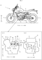
- FIG. 1 is a combination of a left-side view of the straddled vehicle 1 and a schematic view that shows the positions of an engine 10, a clutch actuator 30, and a shift actuator 40 in the straddled vehicle 1.
- the straddled vehicle 1 includes an engine 10, a multi-speed transmission 20, a front wheel 20, a rear wheel 3 serving as a drive wheel, a seat 4, and a vehicle frame 5. Power outputted from the engine 10 is transmitted to the rear wheel 3 via the multi-speed transmission 20, and thereby, the rear wheel 3 rotates to move the straddled vehicle 1.
- the engine 10 is a parallel multicylinder engine.
- the engine 10 is a parallel three-cylinder engine with three cylinders 11 arranged in parallel with one another. Accordingly, the engine 10 of the straddled vehicle 1 of the first embodiment has a greater size in the left-right direction X than a single-cylinder engine or a twin-cylinder engine, and in the rear Rr of the cylinders 11, there is a space that is large in the left-right direction X.
- the engine 10 has a large size in the left-right direction X and is suited for horizontal layout of actuators (horizontal arrangement of motors).
- the engine 10 has a crankcase 12 and a crankshaft 17 in addition to the cylinders 11.
- the cylinders 11 are placed in a posture such that the upper Up thereof (cylinder head) is inclined frontward Fr.
- the axis C1 of the crankshaft 17 extends in the left-right direction X (see FIG. 5(a) ).
- the crankcase 12 has a crankcase body 13, a case cover 14, a clutch cover 15, and a chain cover 16.
- the crankcase body 13 supports the crankshaft 17.
- the crankcase body 13 is a left-right separable type.
- the case cover 14 is located on the left L of the crankcase body 13.
- the clutch cover 15 is located on the right R of the crankcase body 13.
- the chain cover 16 is located on the left L of the crankcase body 13.
- the multi-speed transmission 20 changes the transmission gear ratio between the engine 10 and the drive wheel (rear wheel 3 in this embodiment) in a multistep manner.
- the multi-speed transmission 20 changes the transmission gear ratio in accordance with operation of the rider of the straddled vehicle 1 in a multistep manner.
- the multi-speed transmission 20 is rotatably supported by the crankcase 12.
- the multi-speed transmission 20 includes an input shaft 21, an output shaft 22, a clutch 23, a shifter mechanism 24, a clutch actuator 30, and a shift actuator 40.
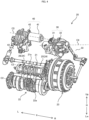
- the input shaft 21 is rotatably supported by the crankcase body 13. As shown in FIG. 4 , a plurality of drive gears 21a are attached to the input shaft 21.
- the output shaft 22 is rotatably supported by the crankcase 12. As shown in FIG. 4 , additionally, a plurality of driven gears 22a that engage with the drive gears 21a are attached to the output shaft 22.
- the output shaft 22 outputs power toward the rear wheel 3. As shown in FIG. 4 , the axis C2 of the input shaft 21 and the axis C3 of the output shaft 22 extend in the left-right direction X.
- the shifter mechanism 24 includes a shift shaft 25 and a shift cam 26.
- the shift actuator 30 is linked with the shift shaft 25 and transmits power.
- the shift cam 26 rotates, whereby the gears on the input shaft 21 and output shaft 22 move in the axial direction, and in this way, a shift change is conducted.
- the clutch 23 is located on a power transmission pathway from the crankshaft 17 to the output shaft 22.
- the clutch 23 is attached to the input shaft 21.
- the clutch 23 is a multiplate friction clutch.
- the clutch 23 is not only used to start moving the vehicle but also functions as a shift clutch that is disengaged for a shift change.
- the power transmission pathway is from the crankshaft 17, the input shaft 21, the drive gears 21a, the driven gears 22a, and to the output shaft 22 in this order.
- the clutch actuator 30 and the shift actuator 40 constitute a shifting assist device that assists the rider's action for a shift change (the rider's shifting action).
- the shift motor 41 and the clutch motor 31 operate when the straddled vehicle 1 changes the shift (i.e., when the multi-speed transmission 20 conducts a shift change).
- the shift motor 41 and the clutch motor 31 operate.
- the time for a shift change of the straddled vehicle 1 is determined, for example, by the rider's operation of a shifting operation element (for example, a shift switch) provided in the straddled vehicle 1.
- the clutch actuator 30 includes the clutch motor 31, and a clutch gear box 32 containing a deceleration mechanism to which power of the clutch motor 31 is transmitted.
- This deceleration mechanism of the clutch actuator 30 is located on a power transmission pathway from the clutch motor 31 to the clutch 23.
- the shift actuator 40 includes the shift motor 41, and a shift gear box 42 containing a deceleration mechanism to which power of the shift motor 41 is transmitted.
- This deceleration mechanism of the shift actuator 40 is located on a power transmission pathway from the shift motor 41 to the shifter mechanism 24.
- the multi-speed transmission 20 includes, in addition to the components above, a first coupling device 33 (a lever, a rod, etc.) that connects the clutch actuator 30 and the clutch 23, a second coupling device 43 (a lever, a rod, etc.) that connects the shift actuator 40 and the shifter mechanism 24.
- a first coupling device 33 a lever, a rod, etc.
- a second coupling device 43 a lever, a rod, etc.
- Each component (lever, rod or the like) of the first coupling device 33 and the second coupling device 43 is displaceable within a specified range.
- each of the first coupling device 33 and the second coupling device 43 is a member that requires a motion range.
- the clutch actuator 30 is an outer-pull type that is powered on from the outside of the clutch 23.
- case centerline C6 means a line that includes a midpoint P1, with respect to the left-right direction X, of the crankcase 12 and extends in the front-rear direction Y.
- case center hypothetical plane F1 means a hypothetical plane that passes the case centerline C6 and spreads in the up-down direction H (see FIG. 3 ).
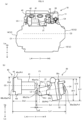
- inter-axial distance L2 means the distance from a first intersection point Pk1 between the case center hypothetical plane F1 and the axis C4 of the clutch motor 31 to a second intersection point Pk2 between the case center hypothetical plane F1 and the axis C5 of the shift motor 41 (see FIG. 6(b) ).
- clutch actuator front-to-rear entire length Dy1 means the length in the front-rear direction Y of the clutch actuator 30, from the front end 30f to the rear end 30r, when the clutch actuator 30 is positioned in the straddled vehicle 1 (see FIG. 5(b) ).
- shift actuator front-to-rear entire length Dy2 means the length in the front-rear direction Y of the shift actuator 40, from the front end 40f to the rear end 40r, when the shift actuator 40 is positioned in the straddled vehicle 1 (see FIG. 5(b) ).
- front-end reference position Py1 means either one of the front end 30f of the clutch actuator 30 and the front end 40f of the shift actuator 40 that is located more frontward Fr than the other (see FIG. 5(b) ).
- rear-end reference position Py2 means either one of the rear end 30r of the clutch actuator 30 and the rear end 40r of the shift actuator 40 that is located more rearward Rr than the other.
- front-rear arrangement distance Ly1 means the distance in the front-rear direction Y between the front-end reference position Py1 and the rear-end reference position Py2.
- clutch actuator left-to-right entire length Dx1 means the length from the outer end 32a, with respect to the left-right direction X, of the clutch gear box 32 (right end of the clutch actuator 30) to the tip 31a of the clutch motor 31 (left end of the clutch actuator 30) when the clutch actuator 30 is positioned in the straddled vehicle 1 (see FIG. 6(b) ).
- shift actuator left-to-right entire length Dx2 means the length from the outer end 42a, with respect to the left-right direction X, of the shift gear box 42 (left end of the shift actuator 40) to the tip 41a of the shift motor 41 (right end of the shift actuator 40) when the shift actuator 40 is positioned in the straddled vehicle 1 (see FIG. 6(b) ).
- right-end reference position Px1 means either one of the right end 30a of the clutch actuator 30 and the right end 40a of the shift actuator 40 that is located more rightward R than the other.
- left-end reference position Px2 means either one of the left end 30b of the clutch actuator 30 and the left end 40b of the shift actuator 40 that is located more leftward L than the other (see FIG. 6(b) ).
- left-right arrangement distance Lx1 means the distance in the left-right direction X between the right-end reference position Px1 and the left-end reference position Px2.
- clutch actuator upper-to-lower entire length Dh1 means the length in the up-down direction H of the clutch actuator 30, from the upper end 30u to the lower end 301.
- shift actuator upper-to-lower entire length Dh2 means the length in the up-down direction H of the shift actuator 40, from the upper end 40u to the lower end 401.
- upper-end reference position Ph1 means either one of the upper end 30u of the clutch actuator 30 and the upper end 40u of the shift actuator 40 that is located more upward Up than the other.
- lower-end reference position Ph2 means either one of the lower end 301 of the clutch actuator 30 and the lower end 401 of the shift actuator 40 that is located more downward Lw than the other.
- up-down arrangement distance Lh1 means the distance in the up-down direction H between the upper-end reference position Ph1 and the lower-end reference position Ph2.
- first region R1 means a region that in a looking-to-the-right or -left view, is between a straight line that extends in the up-down direction H passing through the rear end 12r, with respect to the front-rear direction Y, of the crankcase 12 (up-down hypothetical line K4) and the rear edge 11e of the cylinders 11 and is between a straight line that extends in the front-rear direction Y passing through the upper end 11u, with respect to the up-down direction H, of the cylinders 11 (front-rear hypothetical line K2) and the upper edge 12e of the crankcase 12 (see FIG. 1 (b-1)).
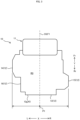
- the "first region R1" is described in more detail with reference to FIG. 2(a) .
- the "rear edge lIe of the cylinders 11" is a line that is seen as the edge of the rear faces 11f of the cylinders 11 (edge line K1) in a looking-to-the-right or -left view (which will hereinafter be referred to as "in a side view” in some cases).
- the "rear edge 11e of the cylinders 11” is a line that passes on the rear faces 11f of the cylinders 11 (i.e., is included in the rear faces 11f of the cylinders 11) and, in a side view, forms a boundary between the cylinders 11 and others (other components or space).
- the "the upper end 11u, with respect to the up-down direction H, of the cylinders 11" is the uppermost (Up) point of the cylinders 11 in a side view.
- the "straight line that extends in the front-rear direction Y passing through the upper end 11u of the cylinders 11" is a straight line that, in a side view, passes through the upper end 11u of the cylinder 11 and extends in the front-rear direction Y (front-rear hypothetical line K2).
- the "upper edge 12e of the crankcase 12" is a line that is seen as the edge of the upper face 12f of the crankcase 12 (the upper (Up) edge line of the crankcase 12) in a side view. From another perspective, the “upper edge 12e of the crankcase 12” is a line that passes on the upper face 12f of the crankcase 12 (i.e., is included in the upper face 12f of the crankcase 12) and, in a side view, forms a boundary between the crankcase 12 and others (other components or space).
- the upper edge 12e of the crankcase 12 is an edge line K3 that is formed of an edge line of the left (L) portion of the crankcase 12 (in a left-side view, a first boundary line K3a and a third boundary line K3c in the near side) and an edge line of the right (R) portion of the crankcase 12 (in the left-side view, a second boundary line K3b in the far side).
- the "the rear end 12r, with respect to the front-rear direction Y, of the crankcase 12" is the rearmost (Rr) point of the crankcase 12 in a side view.
- the "straight line that extends in the up-down direction H passing through the rear end 12r, with respect to the front-rear direction Y, of the crankcase 12" is a straight line that, in a side view, passes through the rear end 12r of the crankcase 12 and extends in the up-down direction H (up-down hypothetical line K4).
- the "first region R1" is a region that, in a side view, is enclosed by the rear edge 11e of the cylinders 11 (edge line K1), the upper edge 12e of the crankcase 12 (edge line K3), the front-rear hypothetical line K2, and the up-down hypothetical line K4.
- hyperthetical tangent line C7 is a tangent line that includes tangential points Ps in the upper portion 1 1a of the cylinders 11 and in the rear portion 12a of the crankcase 12. As shown in FIG. 2(b) , in the straddled vehicle 1 of this embodiment, the hypothetical tangent line C7 includes a tangential point Ps1 in the upper portion 11a of the cylinders 11. Additionally, the hypothetical tangent line C7 includes a tangential point Ps2 in the rear portion 12a of the crankcase 12.
- the “lower region R2" is a region that is lower Lw than the hypothetical tangent line C7 in a side view. As shown in FIG. 2(b) , the "lower region R2" is included in the "first region R1". In other words, in the first region R1, a region that is bounded by and lower Lw than the hypothetical tangent line C7 is the lower region R2.
- a "third region R3" defined by the outer edge 12g of the crankcase 12 is a region that is enclosed by the outer edge 12g of the crankcase 12 in a looking-to-the-down view (which will hereinafter be referred to as "in a plan view” in some cases).
- the "third region R3" is an inner region bounded by the edge line K5 (outer edge 12g) of the crankcase 12 in a plan view.
- each of the clutch actuator 30 and the shift actuator 40 is at least partly positioned between the straight line that extends in the up-down direction H passing through the rear end 12r, with respect to the front-rear direction Y, of the crankcase 12 (up-down hypothetical line K4) and the rear edge 11e of the cylinders 11 and between the straight line that extends in the front-rear direction Y passing through the upper end 11u, with respect to the up-down direction H, of the cylinders 11 (front-rear hypothetical line K2) and the upper edge 12e
- the actuators 30 and 40 are attached to the engine 10 not via the vehicle frame 5 such that each of the actuators 30 and 40 is at least partly positioned in the first region R, the actuators 30 and 40 can be located close to the engine 10 by effective use of the space in the rear of the engine (first region R1), and the clutch gear box 32, the clutch motor 31, the shift motor 41, and the shift gear box 42 can be arranged in this order in the left-right direction X close to one another, i.e., compactly.
- the cylinders 11 and above (Up) the crankcase 12 various components (for example, an air cleaner, a rear suspension, etc.) are located, and the space there is limited.
- the actuators 30 and 40 of the multi-speed transmission 20 can be positioned close to the engine 10 and can be compactly arranged within the limited space. Since the straddled vehicle 1 is a vehicle that turns in accordance with the rider's weight shift, downsizing is highly demanded. In the straddled vehicle 1, the actuators 30 and 40 constituting the multi-speed transmission 20 can be arranged compactly, which contributes to downsizing of the vehicle.
- the clutch gear box 32 is positioned on the right R of the case centerline C6, and the shift gear box 42 is positioned on the left L of the case centerline C6.
- the clutch actuator 30 and the shift actuator 40 are arranged such that the clutch gear box 32, the clutch motor 31, the shift motor 41, the shift gear box 42 are arranged in this order in the left-right direction X from right R. As shown in FIG. 5(a) , in the straddled vehicle 1 of the first embodiment, the clutch gear box 32 is positioned on the right R of the case centerline C6, and the shift gear box 42 is positioned on the left L of the case centerline C6.
- the clutch actuator 30 and the shift actuator 40 are arranged such that the clutch gear box 32, the clutch motor 31, the shift motor 41, the shift gear box 42 are arranged in this order in the left-right direction X from right R.
- the shift gear box 42, the shift motor 41, and the clutch gear box 32 are positioned on a straight line (for example, on the axis C5 of the shift motor 41), and the clutch motor 31 is positioned lower Lw than the axis C5 of the shift motor 41.
- the clutch actuator 30 and the shift actuator 40 are positioned within the third region R3.
- the clutch actuator 30 is positioned low (Lw) relative to the shift actuator 40. More specifically, as shown in FIG. 6 , in a rear view, the clutch gear box 32 is positioned low (Lw) relative to the shift gear box 42, and the clutch motor 31 is positioned low (Lw) relative to the shift motor 41.
- the respective axes of the clutch motor 31 and the shift motor 41 extend in the left-right direction X.
- the axis C5 of the shift motor 41 extends substantially parallel to the left-right direction X. Accordingly, the axis C5 of the shift motor 41 is parallel to the respective axes of the crankshaft 17, the input shaft 21, and the output shaft 22.
- the clutch motor 31 is inclined such that the tip 31a thereof faces down Lw and front Fr relative to its base end 31b.
- the axis C4 of the clutch motor 31 is at an angle to the left-right direction X.
- the axis C4 of the clutch motor 31 is at an angle with (is inclined from) the axes parallel to the left-right direction X (the axis C5 of the shift motor 41, the axis C1 of the crankshaft 17, the axis C2 of the input shaft 21, and the axis C3 of the output shaft 22).
- the axis C4 of the clutch motor 31 from the base end 31b to the tip 31a is at an acute angle (within ⁇ 45 degrees) to the left-right direction X.
- the front-end reference position Py1 is the front end 40f of the shift actuator 40, which is positioned more frontward Fr than the front end 30f of the clutch actuator 30.
- the rear-end reference position Py2 is the rear end 30r of the clutch actuator 30, which is positioned more rearward Rr than the rear end 40r of the shift actuator 40.
- the front-rear arrangement distance Ly1 is shorter than the total of the clutch actuator front-to-rear entire length Dy1 and the shift actuator front-to-rear entire length Dy2 (front-rear arrangement distance Ly1 ⁇ clutch actuator front-to-rear entire length Dy1 + shift actuator front-to-rear entire length Dy2).
- the front-rear arrangement distance Ly1 is shorter than the total of the clutch actuator front-to-rear entire length Dy1 and the shift actuator front-to-rear entire length Dy2 (front-rear arrangement distance Ly1 ⁇ clutch actuator front-to-rear entire length Dy1 + shift actuator front-to-rear entire length Dy2).
- the left-right arrangement distance Lx1 is shorter than the total of the clutch actuator left-to-right entire length Dx1 and the shift actuator left-to-right entire length Dx2 (left-right arrangement distance Lx1 ⁇ clutch actuator left-to-right entire length Dx1 + shift actuator left-to-right entire length Dx2).
- the straddled vehicle 1 within the arrangement range in the left-right direction X of the clutch actuator 30 and the shift actuator 40, there is an overlap part where the clutch actuator 30 and the shift actuator 40 overlap (left-right overlap part Lx2).
- the upper-end reference position Ph1 is the upper end 40u of the shift actuator 40, which is positioned more upward Up than the upper end 30u of the clutch actuator 30.
- the lower-end reference position Ph2 is the lower end 30l of the clutch actuator 30, which is positioned more downward Lw than the lower end 40l of the shift actuator 40.
- the up-down arrangement distance Lh1 is shorter than the total of the clutch actuator upper-to-lower entire length Dh1 and the shift actuator upper-to-lower entire length Dh2 (up-down arrangement distance Lh1 ⁇ clutch actuator upper-to-lower entire length Dh1 + shift actuator upper-to-lower entire length Dh2).
- up-down arrangement distance Lh1 ⁇ clutch actuator upper-to-lower entire length Dh1 + shift actuator upper-to-lower entire length Dh2
- there is an overlap part where the clutch actuator 30 and the shift actuator 40 overlap (up-down overlap part Lh2).
- the clutch actuator 30 and the shift actuator 40 overlap in a side view (for example, in a left-side view). More specifically, as shown in FIG. 7 , in the straddled vehicle 1, the clutch gear box 32 and the shift gear box 42 at least partly overlap in a view from the left-right direction X.
- the clutch actuator 30 and the shift actuator 40 are attached to the crankcase 12.
- two bosses 51 are formed on each of the clutch actuator 30 and the shift actuator 40.
- a plurality of bosses 18 are formed on the crankcase 12.
- Each of the actuators 30 and 40 is attached to the crankcase 12 by bolts 52.
- each of the actuators 30 and 40 is attached to the engine 10 (crankcase 12) not via the vehicle frame 5.
- the shift actuator 40 has two bosses 51 in the lower (Lw) portion of the shift gear box 42, and these two bosses 51 are formed at a distance from each other in the front-rear direction Y.
- the crankcase 12 has two bosses 18 in the left (L) portion thereof (the upper (Up) portion of the case cover 14).
- the clutch actuator 30 has two bosses 51 in the lower (Lw) portion of the clutch gear box 32, and these two bosses 51 are formed at a distance from each other in the front-rear direction Y. Also, two bosses 18 are formed in the right (R) portion of the crankcase 12 (the upper (Up) portion of the clutch cover 15). By connecting the bosses 51 of the clutch actuator 30 and the bosses 18 of the crankcase 12 by bolts 52, the clutch actuator 30 is attached to the crankcase 12.
- each of the actuators 30 and 40 is at least partly positioned in the first region R1 in a side view.
- each of the clutch motor 31 and the shift motor 41 is at least partly positioned lower Lw than the hypothetical tangent line C7 (in the lower region R2).
- each of the actuators 30 and 40 is almost entirely positioned in the lower region R2.
- both the clutch motor 31 and the shift motor 41 are positioned within the lower region R2.
- a straddled vehicle 60 according to a second embodiment of an MT straddled vehicle equipped with a parallel multicylinder engine of the present teaching is described. A drawing of the whole straddled vehicle 60 is omitted. As with the straddled vehicle 1 according to the first embodiment, the straddled vehicle 60 has a front wheel 2, a rear wheel 3, a multi-speed transmission 20, etc.
- the straddled vehicle 60 of the second embodiment includes an engine 70 that is a parallel twin-cylinder engine. As shown in FIG. 8 , the engine 70 is a parallel multicylinder engine. In the straddled vehicle 60 of the second embodiment, the engine 70 is a parallel twin-cylinder engine with two cylinders 71 arranged in parallel.
- the components of the straddled vehicle 60 are the same in structure as the components of the straddled vehicle 1 of the first embodiment. Therefore, in the following description of the arrangement of the actuators 30 and 40 in the straddled vehicle 60 of the second embodiment, the same reference signs as used in the description of the straddled vehicle 1 of the first embodiment will be used, and a detailed description of the structure will be omitted.
- the clutch gear box 32 is located on the right R of the case centerline C6, and the shift gear box 42 is located on the left L of the case centerline C6.
- the clutch gear box 32, the clutch motor 31, the shift motor 41, and the shift gear box 42 are arranged in the left-right direction X in this order from right R.
- the shift gear box 42, the shift motor 41, and the clutch gear box 32 are positioned on a straight line (for example, on the axis C5 of the shift motor 41), and the clutch motor 31 is positioned off the axis C5.
- the clutch actuator 30 and the shift actuator 40 are located within the third region R3.
- the shift actuator 40 is positioned in front Fr relative to the clutch actuator 30.
- the respective axes of the clutch motor 30 and the shift motor 40 extend in the left-right direction X.
- the axis C4 of the clutch motor 31 and the axis C5 of the shift motor 41 are substantially parallel to the left-right direction X. Accordingly, the axis C4 of the clutch motor 30 and the axis C5 of the shift motor 41 are parallel to the respective axes of the crankshaft 17, the input shaft 21, and the output shaft 22.
- the left-right arrangement distance Lx1 is shorter than the total of the clutch actuator left-to-right entire length Dx1 and the shift actuator left-to-right entire length Dx2 (left-right arrangement distance Lx1 ⁇ clutch actuator left-to-right entire length Dx1 + shift actuator left-to-right entire length Dx2).
- the straddled vehicle 60 within the arrangement range in the left-right direction X of the clutch actuator 30 and the shift actuator 40, there is an overlap part where the clutch actuator 30 and the shift actuator 40 overlap (left-right overlap part Lx2).
- the clutch actuator 30 and the shift actuator 40 are attached to the crankcase 12.
- two bosses 51 are formed on each of the clutch actuator 30 and the shift actuator 40.
- a plurality of bosses 18 are formed on the crankcase 12.
- Each of the actuators 30 and 40 is attached to the crankcase 12 by bolts 52.
- each of the actuators 30 and 40 is attached to the engine 70 (crankcase 12) not via the vehicle frame 5.
- the shift actuator 40 has two bosses 51 in the lower (Lw) portion of the shift gear box 42, and these two bosses 51 are formed at a distance from each other in the front-rear direction Y.
- the crankcase 12 has two bosses 18 in the left (L) portion thereof (the upper (Up) portion of the case cover 14).
- the clutch actuator 30 has two bosses 51 in the lower (Lw) portion of the clutch gear box 32, and these two bosses 51 are formed at a distance from each other in the front-rear direction Y.
- the crankcase 12 has two bosses 18 in the right (R) portion thereof (the upper (Up) portion of the clutch cover 15).
- each of the actuators 30 and 40 is at least partly positioned in the first region R1 in a side view.
- each of the clutch motor 31 and the shift motor 41 is at least partly positioned lower Lw than the hypothetical tangent line C7 (in the lower region R2).
- each of the actuators 30 and 40 is almost entirely positioned in the lower region R2.
- both the clutch motor 31 and the shift motor 41 are positioned within the lower region R2.
- the front-end reference position Py1 is the front end 40f of the shift actuator 40, which is positioned more frontward Fr than the front end 30f of the clutch actuator 30.
- the rear-end reference position Py2 is the rear end 30r of the clutch actuator 30, which is positioned more rearward Rr than the rear end 40r of the shift actuator 40.
- the front-rear arrangement distance Ly1 is shorter than the total of the clutch actuator front-to-rear entire length Dy1 and the shift actuator front-to-rear entire length Dy2 (front-rear arrangement distance Ly1 ⁇ clutch actuator front-to-rear entire length Dy1 + shift actuator front-to-rear entire length Dy2).
- the front-rear arrangement distance Ly1 is shorter than the total of the clutch actuator front-to-rear entire length Dy1 and the shift actuator front-to-rear entire length Dy2 (front-rear arrangement distance Ly1 ⁇ clutch actuator front-to-rear entire length Dy1 + shift actuator front-to-rear entire length Dy2).
- the upper-end reference position Ph1 is the upper end 30u of the clutch actuator 30, which is positioned more upward Up than the upper end 40u of the shift actuator 40.
- the lower-end reference position Ph2 is the lower end 40l of the shift actuator 40, which is positioned more downward Lw than the lower end 30l of the clutch actuator 30.
- the up-down arrangement distance Lh1 is shorter than the total of the clutch actuator upper-to-lower entire length Dh1 and the shift actuator upper-to-lower entire length Dh2 (up-down arrangement distance Lh1 ⁇ clutch actuator upper-to-lower entire length Dh1 + shift actuator upper-to-lower entire length Dh2).
- up-down arrangement distance Lh1 ⁇ clutch actuator upper-to-lower entire length Dh1 + shift actuator upper-to-lower entire length Dh2
- there is an overlap part where the clutch actuator 30 and the shift actuator 40 overlap (up-down overlap part Lh2).
- the clutch actuator 30 and the shift actuator 40 overlap in a side view (for example, in a left-side view). More specifically, as shown in FIG. 9 , in the straddled vehicle 60, the clutch gear box 32 and the shift gear box 42 at least partly overlap in a view from the left-right direction X.
- an air cleaner 6 is located above (Up) the crankcase 12, and a rear suspension 7 is located behind (Rr) the crankcase 12.
- the actuators 30 and 40 are arranged in the first region R1, and the motors 31 and 41 are arranged such that their respective axes C4 and C5 extend in the left-right direction X. Because of these and other ingenious arrangements, the limited space is effectively used.
- the space behind the cylinders which is limited by other components (air cleaner 6, rear suspension 7, etc.) is effectively used, and the actuators 30 and 40 can be compactly arranged.
Landscapes
- Engineering & Computer Science (AREA)
- General Engineering & Computer Science (AREA)
- Mechanical Engineering (AREA)
- Gear-Shifting Mechanisms (AREA)
Abstract
Description
- The present teaching relates to an MT straddled vehicle equipped with a parallel multicylinder engine that includes a multi-speed transmission wherein the acting force of an actuator can be inputted to a clutch or a speed changer.
- Conventionally, an MT straddled vehicle equipped with a parallel multicylinder engine that includes a multi-speed transmission to which the acting force of an actuator can be inputted to assist in the rider's shifting action has been provided. Such an MT straddled vehicle equipped with a parallel multicylinder engine that includes a multi-speed transmission has a clutch actuator and a shift actuator that constitute the multi-speed transmission. A straddled vehicle with a multi-speed transmission is disclosed, for example, in
Patent Literature 1 below. - Patent Literature 1:
Japanese Patent Application Publication No. 2006-17221 - An MT straddled vehicle equipped with a parallel multicylinder engine is a vehicle that turns by a weight shift of the rider. Therefore, downsizing of the vehicle is highly needed. If such an MT straddled vehicle equipped with a parallel multicylinder engine is designed to meet the need for downsizing and to contain a multi-speed transmission as described above, the space for arrangement of the components is limited. Then, an MT straddled vehicle equipped with a parallel multicylinder engine that includes a multi-speed transmission requires an ingenuity in arrangement of a clutch actuator and a shift actuator that constitute the multi-speed transmission.
- An objective of the present teaching is to provide an MT straddled vehicle equipped with a parallel multicylinder engine that includes a multi-speed transmission that assists the rider's shifting action, wherein a clutch actuator and a shift actuator can be compactly arranged, thereby downsizing the vehicle.
- The inventors of the present application conducted studies about compact arrangement of a clutch actuator and a shift actuator. As a result, the inventors obtained the following findings.
- As mentioned above, downsizing of an MT straddled vehicle equipped with a parallel multicylinder engine is highly demanded, and the space for arrangement of the components is limited. In providing a multi-speed transmission as described above in an MT straddled vehicle equipped with a parallel multicylinder engine, the inventors of the present application studied about the space for arrangement of actuators (a clutch actuator and a shift actuator) constituting the multi-speed transmission. At that time, the inventors of the present application paid attention to the fact that in an MT straddled vehicle equipped with a parallel multicylinder engine, a speed changer and a clutch are both located in the parallel multicylinder engine. Then, the inventors of the present application hit upon an idea of arranging the clutch actuator and the shift actuator near the parallel multicylinder engine and studied whether there is a space for the clutch actuator and the shift actuator near the parallel multicylinder engine. As a result, the inventors of the present application obtained a finding that in the space around the parallel multicylinder engine, there may be a space for the clutch actuator and the shift actuator behind the cylinders and above the crankcase (in the rear of the engine). However, in the space in the rear of the engine, for example, an air cleaner, a rear suspension, a starter motor, a throttle body, a canister, etc., are located, and an ingenuity is required for compact arrangement. Moreover, the actuators constituting the multi-speed transmission may have to be increased in size to generate a needed output. The inventors of the present application furthermore studied about the structure that permits the actuators to be arranged in the limited space in the rear of the engine. As a result, the inventors of the present application obtained a finding that it is possible to compactly arrange the actuators constituting the multi-speed transmission in the limited space by arranging the actuators constituting the multi-speed transmission side by side, on left and right, and by arranging the actuators close to each other. Based on these findings, the present teaching has been made.
- According to some aspects of the present teaching, which has been made based on the findings above, MT straddled vehicles equipped with a parallel multicylinder engine have the following structures.
- (1) An MT straddled vehicle equipped with a parallel multicylinder engine according to an embodiment of the present teaching includes a parallel multicylinder engine and a multi-speed transmission, the parallel multicylinder engine including a plurality of cylinders arranged in parallel, and a crankcase supporting a crankshaft, and in the MT straddled vehicle equipped with a parallel multicylinder engine, the multi-speed transmission comprising: an input shaft that is rotatably supported by the crankcase, a plurality of drive gears being provided on the input shaft; an output shaft that is rotatably supported by the crankcase and outputs power toward a drive wheel, a plurality of driven gears engaging with the drive gears being provided on the output shaft; a clutch located on a power transmission pathway from the crankshaft to the output shaft; a clutch actuator including a clutch motor, and a clutch gear box containing a deceleration mechanism to which power of the clutch motor is transmitted, the deceleration mechanism being located on a power transmission pathway from the clutch motor to the clutch; a shift actuator including a shift motor, and a shift gear box containing a deceleration mechanism to which power of the shift motor is transmitted, the deceleration mechanism being located on a power transmission pathway from the shift motor to a shifter mechanism, and the clutch actuator and the shift actuator are attached to the parallel multicylinder engine not via a vehicle frame in such a manner as to meet the following requirements that: the clutch gear box, the clutch motor, the shift motor, and the shift gear box are arranged in this order in a left-right direction of the vehicle; and in a looking-to-the-right or -left view, each of the clutch actuator and the shift actuator is at least partly positioned between a straight line that extends in an up-down direction of the vehicle passing through a rear end, with respect to a front-rear direction of the vehicle, of the crankcase and a rear edge of the cylinders and between a straight line that extends in the front-rear direction passing through an upper end, with respect to the up-down direction, of the cylinders and an upper edge of the crankcase.
- (1) According to the present teaching, the clutch actuator and the shift actuator are attached to the parallel multicylinder engine not via the vehicle frame such that, in a looking-to-the-right or -left view, each of the actuators is at least partly positioned in a space behind the cylinders and above the crankcase (in a space in the rear of the engine), and specifically, by arranging the clutch gear box, the clutch motor, the shift motor, and the shift gear box in this order in the left-right direction of the vehicle and close to one another while effectively using the space in the rear of the parallel multicylinder engine, these actuators can be compactly arranged near the parallel multicylinder engine. Various components (for example, an air cleaner, a rear suspension, etc.) are located behind the cylinders and above the crankcase, and the space is limited. According to the present teaching, the actuators of the multi-speed transmission can be arranged near the engine compactly in the limited space. The straddled vehicle is a vehicle that turns by the rider's weight shift, and downsizing is highly needed. According to the present teaching, the actuators constituting the multi-speed transmission can be compactly arranged, which contributes to downsizing of the vehicle.
- In an aspect of the present teaching, the MT straddled vehicle equipped with a parallel multicylinder engine may be configured as follows.
- (2) In the straddled vehicle equipped with a parallel multicylinder engine of (1) above, the clutch actuator and the shift actuator are attached to the parallel multicylinder engine not via the vehicle frame in such a manner as to further meet the following requirement that a left-right arrangement distance is shorter than a total of a clutch actuator left-to-right entire length and a shift actuator left-to-right entire length, wherein: the clutch actuator left-to-right entire length is a length in the left-right direction of the clutch actuator, from a right end to a left end, when the clutch actuator is positioned in the vehicle; the shift actuator left-to-right entire length is a length in the left-right direction of the shift actuator, from a right end to a left end, when the shift actuator is positioned in the vehicle; and the left-right arrangement distance is a distance in the left-right direction between a right-end reference position that is either one of the right end of the clutch actuator and the right end of the shift actuator that is located more rightward than the other and a left-end reference position that is either one of the left end of the clutch actuator and the left end of the shift actuator that is located more leftward than the other.
- In the MT straddled vehicle equipped with a parallel multicylinder engine of (2) above, the respective motors of the actuators can be arranged close to each other, and the actuators can be arranged compactly in the left-right direction. More specifically, in arranging the actuators, it is necessary to consider the lengths of the motors. The motors of the actuators need to produce large power to fulfill the functions (shift change, and clutch engagement and disengagement), and therefore, large motors (motors that are large in length or diameter) are used as the motors of the actuators. By overlapping the clutch motor and the shift motor, the lengths of the two motors are offset by each other, and the actuators can be arranged more compactly.
- In another aspect of the present teaching, the MT straddled vehicle equipped with a parallel multicylinder engine may be configured as follows.
- (3) In the MT straddled vehicle equipped with a parallel multicylinder engine of (1) or (2) above, the clutch actuator and the shift actuator are attached to the parallel multicylinder engine not via the vehicle frame in such a manner as to further meet the following requirement that the clutch gear box and the shift gear box are arranged in such a manner as to at least partly overlap in a looking-to-the-right or -left view.
- In the MT straddled vehicle equipped with a parallel multicylinder engine of (3) above, these actuators can be arranged in one side at least in the front-rear direction or in the up-down direction and thereby can be compactly arranged.
- In another aspect of the present teaching, the MT straddled vehicle equipped with a parallel multicylinder engine may be configured as follows.
- (4) In the MT straddled vehicle equipped with a parallel multicylinder engine according to any one of (1) to (3) above, the clutch actuator and the shift actuator are attached to the parallel multicylinder engine not via the vehicle frame in such a manner as to further meet the following requirements that: between the right and the left of a case centerline, the clutch gear box is positioned on one side; and the shift gear box is positioned on the other side, wherein the case centerline is a straight line that includes a midpoint, with respect to the left-right direction, of the crankcase and extends in the front-rear direction.
- In the MT straddled vehicle equipped with a parallel multicylinder engine of (4) above, the actuators can be arranged with the left-right weight balance of the vehicle improved.
- In another aspect of the present teaching, the MT straddled vehicle equipped with a parallel multicylinder engine may be configured as follows.
- (5) In the MT straddled vehicle equipped with a parallel multicylinder engine of any one of (1) to (4) above, the clutch actuator and the shift actuator are attached to the parallel multicylinder engine not via the vehicle frame in such a manner as to further meet the following requirement that each of the clutch motor and the shift motor is at least partly positioned lower than a hypothetical tangent line in a looking-to-the-right or -left view, wherein the hypothetical tangent line is a tangent line that includes a tangential point in an upper portion of the cylinders and a tangential point in a rear portion of the crankcase.
- In the MT straddled vehicle equipped with a parallel multicylinder engine of (5) above, the actuators can be arranged still closer to the engine and can be compactly arranged.
- In another aspect of the present teaching, the MT straddled vehicle equipped with a parallel multicylinder engine may be configured as follows.
- (6) In the MT straddled vehicle equipped with a parallel multicylinder engine according to any one of (1) to (5) above, the clutch actuator and the shift actuator are attached to the parallel multicylinder engine not via the vehicle frame in such a manner as to further meet the following requirement that respective axes of the clutch motor and the shift motor extend in the left-right direction.
- In the MT straddled vehicle equipped with a parallel multicylinder engine of (6) above, for example, by overlapping the two motors in the axial direction, the lengths of the two motors can be offset by each other, and the actuators can be arranged more compactly. Additionally, as the motors, ones of a size adequate to produce the needed power are selected. Specifically, the motors of the actuators need to produce large power to fulfill the functions (shift change, and clutch engagement and disengagement), and therefore, large motors (motors that are large in length or diameter) are used as the motors of the actuators. For example, by arranging the motors such that the respective axes extend in the left-right direction and that the motors overlap in the axial direction, the lengths of the two motors are offset by each other, and the motors can be compactly arranged in the left-right direction.
- In another aspect of the present teaching, the MT straddled vehicle equipped with a parallel multicylinder engine may be configured as follows.
- (7) In the MT straddled vehicle equipped with a parallel multicylinder engine of any one of (1) to (6) above, the clutch actuator and the shift actuator are attached to the parallel multicylinder engine not via the vehicle frame in such a manner as to further meet either the following requirement that a front-rear arrangement distance is shorter than a total of a clutch actuator front-to-rear entire length and a shift actuator front-to-rear entire length or the following requirement that an up-down arrangement distance is shorter than a total of a clutch actuator upper-to-lower entire length and a shift actuator upper-to-lower entire length, wherein: the clutch actuator front-to-rear entire length is a length in the front-rear direction of the clutch actuator, from a front end to a rear end, when the clutch actuator is positioned in the vehicle; the shift actuator front-to-rear entire length is a length in the front-rear direction of the shift actuator, from a front end to a rear end, when the shift actuator is positioned in the vehicle; the front-rear arrangement distance is a distance in the front-rear direction between a front-end reference position that is either one of the front end of the clutch actuator and the front end of the shift actuator that is located more frontward than the other and a rear-end reference position that is either one of the rear end of the clutch actuator and the rear end of the shift actuator that is located more rearward than the other; the clutch actuator upper-to-lower entire length is a length in the up-down direction of the clutch actuator, from an upper end to a lower end, when the clutch actuator is positioned in the vehicle; the shift actuator upper-to-lower entire length is a length in the up-down direction of the shift actuator, from an upper end to a lower end, when the shift actuator is positioned in the vehicle; the up-down arrangement distance is a distance in the up-down direction between an upper-end reference position that is either one of the upper end of the clutch actuator and the upper end of the shift actuator that is located more upward than the other and a lower-end reference position that is either one of the lower end of the clutch actuator and the lower end of the shift actuator that is located more downward than the other.
- In the MT straddled vehicle equipped with a parallel multicylinder engine of (7), the actuators can be arranged compactly in at least one of the up-down direction or the front-rear direction.
- In another aspect of the present teaching, the MT straddled vehicle equipped with a parallel multicylinder engine may be configured as follows.
- (8) In the MT straddled vehicle equipped with a parallel multicylinder engine of any one of (1) to (7) above, the clutch actuator and the shift actuator are attached to the parallel multicylinder engine not via the vehicle frame in such a manner as to further meet the following requirement that each of the clutch actuator and the shift actuator is at least partly positioned in a region enclosed by an outer edge of the crankcase in a looking-to-the-down view.
- In the MT straddled vehicle equipped with a parallel multicylinder engine of (8) above, by use of the region above the crankcase, the actuators can be arranged compactly in the left-right direction.
- Some embodiments of the present teaching will hereinafter be described in detail with reference to the drawings, and the detailed description of the embodiments will provide a clearer picture of the above-mentioned objective and other objectives, the features, the aspects and the advantages of the present teaching. The term "and/or" used herein includes one of the associated items in a list and all possible combinations of the associated items. The terms "including", "comprising", or "having", and variations thereof used herein specify the presence of stated features, steps, operations, elements, components, and/or equivalents thereof, and can include one or more steps, operations, elements, components, and/or one or more of their groups. Unless otherwise defined, all terms (including technical and scientific terms) used herein have the same meanings as commonly understood by one of ordinary skill in the art to which the present teaching pertains. It should be understood that terms, such as those defined in commonly used dictionaries, should be interpreted as having meanings that are consistent with their meanings in the context of the present disclosure and relevant art and should not be interpreted in an idealized or overly formal sense unless expressly so defined herein. It should be understood that the description of the present teaching discloses a number of techniques and steps. Each of these has an individual benefit, and each can also be used in conjunction with one or more, or in some cases all, of the other disclosed techniques. Accordingly, for the sake of clarity, this description will refrain from repeating every possible combination of the individual steps in an unnecessary fashion. Nevertheless, Description and Claims should be read with the understanding that such combinations are entirely within the scope of the present teaching and the claims.
- In the description given below, for the purpose of explanation, numerous specific details are set forth in order to provide a complete understanding of the present teaching. It will be apparent, however, that those skilled in the art may practice the present teaching without these specific details. The present disclosure is to be considered as exemplification of the present teaching and is not intended to limit the present teaching to the specific embodiments illustrated by drawings or descriptions below.
- The MT straddled vehicle equipped with a parallel multicylinder engine is a straddled vehicle that has a parallel multicylinder engine and a manual multi-speed transmission. The straddled vehicle is a vehicle that a rider gets on straddling a saddle. As the straddled vehicle, for example, two-wheel motor vehicles of a moped type, an offroad type and an on-road type can be named. The straddled vehicle is not limited to a two-wheel motor vehicle and may be, for example, a three-wheel motor vehicle, an ATV (all-terrain vehicle) or the like. The three-wheel motor vehicle may have two front wheels and one rear wheel or may have one front wheel and two rear wheels. The drive wheel of the straddled vehicle may be the front wheel(s) or the rear wheel(s). The drive wheel of the straddled vehicle may be both the front wheel(s) and the rear wheel(s). The straddled vehicle may be configured to be able to turn in a leaning posture. The straddled vehicle that is configured to be able to turn in a leaning posture is configured to turn in a posture leaning toward the center of the curve. Thereby, the straddled vehicle that is configured to be able to turn in a leaning posture counteracts centrifugal force applied to the vehicle when the vehicle is turning. The straddled vehicle that is configured to be able to turn in a leaning posture is required to be frisky, and the responsiveness of onward movement to operation to start the vehicle is considered important. The MT straddled vehicle, for example, does not have a torque converter using hydrodynamic action on a power transmission pathway from the engine to the drive wheel.
- The "parallel multicylinder engine" is an engine with a plurality of cylinders arranged in parallel to one another in the left-right direction of the vehicle. The parallel multicylinder engine includes twin-cylinder engines, three-cylinder engines, etc. The engine may be a regular-interval-explosion engine or an irregular-interval-explosion engine. For example, the engine is a four-stroke engine. The engine is, for example, a petrol engine but may be a diesel engine. The engine is, for example, a water-cooled engine but may be an air-cooled engine. The engine is, for example, an inlet-pipe injection type but may be a direct injection type. The crankshaft extends in the left-right direction of the vehicle. Accordingly, the axial direction of the crankshaft is, for example, parallel to the left-right direction of the vehicle. The parallel multicylinder engine may have a speed changer housed in the crankcase.
- The crankcase is configured to support the crankshaft such that the crankshaft is rotatable. The crankcase can be formed of a plurality of components. As the components constituting the crankcase, for example, a crankcase body, a crankcase cover, and a clutch cover can be named. Furthermore, the crankcase body can be formed of a plurality of components. For example, the crankcase body may be configured as a type that is separable into two parts in the left-right direction of the vehicle (vertically separable type) or a type that is separable into three or more parts. The crankcase may be integrated with a cylinder block or may be a separate member from the cylinders. The crankcase cover is located outside of the crankcase body in the left-right direction of the vehicle.
- The statement that "respective axes of the clutch motor and the shift motor extend in the left-right direction" means that the axes of the motors extend roughly in the left-right direction and does not mean that the axial direction of the motors completely coincides with the left-right direction. Accordingly, the axes of these two motors are not necessarily completely parallel to the left-right direction. For example, each of the axes of these motors may form a specified inclination angle with the left-right direction. The statement that each of the axes of the motors forms a specified inclination angle with the left-right direction means that each of the axes of the motors is at a specified angle (for example, at an acute angle within ±45 degrees) to the left-right direction.
- Thus, the axis of the clutch motor and the axis of the shift motor may be parallel to the axis of the crankshaft or may be inclined from the axis of the crankshaft. Additionally, the axis of the clutch motor and the axis of the shift motor may be parallel to the axis of the input or output shaft or may be inclined from the axis of the input or output shaft.
- The multi-speed transmission has a plurality of gear positions. The multi-speed transmission may further have a neutral position. The number of gear positions is not particularly limited and, for example, the multi-speed transmission has four to six gear positions in addition to a neutral position. The multi-speed transmission further may have a reverse position. The multi-speed transmission is, for example, a bottom-neutral type but may be a half-neutral type (bottom-low type). The bottom-neutral type means a shift pattern in which the neutral position is lower than the first position. The half-neutral type means a shift pattern in which the neutral position is between the first position and the second position. The multi-speed transmission is, for example, a return transmission but may be a rotary transmission.
- The input shaft is parallel to or substantially parallel to the crankshaft. The input shaft, for example, has gears that engage with gears provided on the crankshaft, and the input shaft is configured such that power is inputted thereto from the crankshaft via the gears. The input shaft has a plurality of drive gears corresponding to the plurality of gear positions. The plurality of drive gears are arranged, for example, in the axial direction of the input shaft.
- The output shaft is parallel to or substantially parallel to the input shaft. The output shaft has a plurality of driven gears corresponding to the plurality of gear positions. Each of the driven gears engages with the corresponding drive gear. For example, the output shaft has a sprocket, and a drive chain is wound around the sprocket so that power is transmitted to the drive wheel via the drive chain. The way to transmit power from the output shaft to the drive wheel is not limited to this example.
- The shifter mechanism includes a shift shaft and a shift cam. The shift actuator transmits power in conjunction with the shift shaft. When the shift shaft rotates, the shift cam rotates, and the gears on the input shaft and the output shaft move in the axial direction, whereby a gear change is conducted.
- The clutch operates in accordance with the rider's action. For example, the clutch is a start-and-gear-change dual-purpose clutch of which engaged or disengaged state is changed both at a time of starting to move the vehicle and at a time of changing the gear position. The clutch may be a multiplate or single plate clutch of a wet or dry type.
- The clutch actuator includes a clutch motor, and a clutch gear box that contains a deceleration mechanism to which the power of the clutch motor is transmitted. For example, the deceleration mechanism is formed of a plurality of gears located on a power transmission pathway from the clutch motor to the clutch. The clutch motor is a motor used to engage and disengage the clutch.
- The shift actuator includes a shift motor, and a shift gear box that contains a deceleration mechanism to which the power of the shift motor is transmitted. For example, the deceleration mechanism is formed of a plurality of gears located on a power transmission pathway from the shift motor to the shifter mechanism. This deceleration mechanism is located on the power transmission pathway from the shift motor to the shifter mechanism. The clutch motor and the shift motor are not particularly limited, and well-known conventional motors can be used.
- The statement that "the clutch actuator and the shift actuator are attached to the parallel multicylinder engine not via a vehicle frame" means that each of the actuators is directly attached to the parallel multicylinder engine or indirectly attached to the parallel multicylinder engine via a bracket or the like.
- The term "arranged in the left-right direction" does not necessarily mean being positioned on one straight line. The term "arranged in the left-right direction" means being arranged in a specified order from right or from left. Thus, cases expressed by "arranged in the left-right direction" include cases in which some part of the things is off the straight line.
- The term "in a looking-to-the-right or -left view" means in a side view (a right-side view or a left-side view) of the straddled vehicle.
- The term "rear edge of the cylinders" is a line seen in a side view as the edge of the rear faces of the cylinders (rear edge line of the cylinders). From another perspective, the "rear edge of the cylinders" is a line that is on the rear faces of the cylinders (is included in the rear faces of the cylinders) and, in a side view, forms a boundary (is a boundary line) between the cylinders and others (other components or space).
- The term "upper end of the cylinders" is a point seen in a side view as the uppermost point of the cylinders. The term "straight line extending in the front-rear direction passing through an upper end, with respect to the up-down direction, of the cylinders" means a hypothetical line that, in a side view, extends in the front-rear direction passing through the upper end of the cylinders (front-rear hypothetical line).
- The term "upper edge of the crankcase" is a line seen in a side view as the edge of the upper face of the crankcase (upper edge line of the crankcase). From another perspective, the "upper edge of the crankcase" is a line that is on the upper face of the crankcase (is included in the upper face of the crankcase) and, in a side view, forms a boundary (is a boundary line) between the crankcase and others (other components or space).
- The term "rear end of the crankcase" is a point seen in a side view as the rearmost point of the crankcase. The term "straight line that extends in an up-down direction of the vehicle passing through a rear end, with respect to a front-rear direction of the vehicle, of the crankcase" means a straight line that, in a side view, extends in the up-down direction passing through the rear end of the crankcase (up-down hypothetical line).
- The statement that "in a looking-to-the-right or -left view, each of the clutch actuator and the shift actuator is at least partly positioned between a straight line that extends in an up-down direction of the vehicle passing through a rear end, with respect to a front-rear direction of the vehicle, of the crankcase and a rear edge of the cylinders and between a straight line that extends in the front-rear direction of the vehicle passing through an upper end, with respect to the up-down direction, of the cylinders and an upper edge of the crankcase" means that in a side view, each of the clutch actuator and the shift actuator is at least partly positioned in a region enclosed by the rear edge of the cylinders (rear edge line of the cylinders in a side view), the upper edge of the crankcase (upper edge line of the crankcase in a side view), the front-rear hypothetical line, and the up-down hypothetical line.
- The statement that in a looking-to-the right or -left view, each of the clutch motor and the shift motor is at least partly positioned lower than a hypothetical tangent line means that in a side view, when a region above the hypothetical tangent line is defined as an upper region and a region below the hypothetical tangent line is defined as a lower region, each of the clutch motor and the shift motor is at least partly positioned in the lower region.
- The "lower region" is a region included in the region "between a straight line that extends in an up-down direction of the vehicle passing through a rear end, with respect to a front-rear direction of the vehicle, of the crankcase and a rear edge of the cylinders and between a straight line that extends in the front-rear direction of the vehicle passing through an upper end, with respect to the up-down direction, of the cylinders and an upper edge of the crankcase" in a side view. More specifically, the region "between a straight line that extends in an up-down direction of the vehicle passing through a rear end, with respect to a front-rear direction of the vehicle, of the crankcase and a rear edge of the cylinders and between a straight line that extends in the front-rear direction of the vehicle passing through an upper end, with respect to the up-down direction, of the cylinders and an upper edge of the crankcase" in a side view is divided, in a side view, by the hypothetical line into an upper region that is above the hypothetical tangent line and a lower region that is below the hypothetical tangent line.
- The statement that "each of the clutch actuator and the shift actuator is at least partly positioned in a region enclosed by an outer edge of the crankcase in a looking-to-the-down view" means that in a plan view of the straddled vehicle, each of the clutch actuator and the shift actuator is at least partly positioned in a region defined by the edge line (outer edge) of the crankcase.
- The positions of the clutch actuator and the shift actuator relative to each other are not limited. Specifically, it does not matter which of the clutch gear box and the shift gear box is positioned on the right. For example, the clutch gear box may be positioned on the right of the case centerline, and the shift gear box may be positioned on the left of the case centerline. Or the clutch gear box may be positioned on the left of the case centerline, and the shift gear box may be positioned on the right of the case centerline. Also, either one of the clutch actuator and the shift actuator may be positioned more frontward than the other, or these actuators may be located substantially at the same position in the front-rear direction. For example, one of the actuators may be positioned within the region of the front-to-rear entire length of the other actuator.
- The term "left-right arrangement distance" means the distance in the left-right direction between the rightmost one of the respective right ends of the actuators and the leftmost one of the respective left ends of the actuators. Thus, when these two actuators are arranged such that the left-to-right entire length of one of the actuators is within the region occupied by the left-to-right entire length of the other actuator, there may be a relation of left-right arrangement distance = left-to-right entire length of clutch actuator or left-to-right entire length of shift actuator.
- The term "front-rear arrangement distance" means the distance in the front-rear direction between the frontmost one of the respective front ends of the actuators and the rearmost one of the respective rear ends of the actuators. Thus, when these two actuators are arranged such that the front-to-rear entire length of one of the actuators is within the region occupied by the front-to-rear entire length of the other actuator, there may be a relation of front-rear arrangement distance = front-to-rear entire length of clutch actuator or front-to-rear entire length of shift actuator.
- The term "up-down arrangement distance" means the distance in the up-down direction between the uppermost one of the respective upper ends of the actuators and the lowermost one of the respective lower ends of the actuators. Thus, when these two actuators are arranged such that the upper-to-lower entire length of one of the actuators is within the region occupied by the upper-to-lower entire length of the other actuator, there may be a relation of up-down arrangement distance = upper-to-lower entire length of clutch actuator or upper-to-lower entire length of shift actuator.
- A shift coupling device (a rod, a lever, etc.) that connects the shifter mechanism and the shift actuator may be located outward from the shift actuator in the left-right direction. Also, a clutch coupling device (a rod, a lever, etc.) that connects the clutch and the clutch actuator may be located outward from the clutch actuator in the left-right direction. Such a structure improves the flexibility in arranging the coupling devices (rods, levers, etc.). Accordingly, the motion space for the rods and levers can be obtained easily. This also offers the benefit of improving the work easiness in attaching components of the coupling devices.
- In the MT straddled vehicle equipped with a parallel multicylinder engine according to the present teaching, the distance between the axis of the clutch motor and the axis of the shift motor (inter-axial distance) is preferably not more than a specified distance. In the MT straddled vehicle equipped with a parallel multicylinder engine according to the present teaching, for example, the inter-axial distance of the motors is preferably shorter than either one of the left-right arrangement distance, the up-down arrangement distance and the front-rear arrangement distance. In such a structure, the motors can be arranged close to each other, and the actuators can be compactly arranged.
- The "inter-axial distance" is the distance from a first intersection point and a second intersection point, wherein: the first intersection point is an intersection point between a case center hypothetical plane and the axis of the clutch motor; and the second intersection point is an intersection point between the case center hypothetical plane and the axis of the shift motor. The "case center hypothetical plane is a hypothetical plane that passes the case centerline and spreads in the up-down direction.
- The present teaching provides an MT straddled vehicle equipped with a parallel multicylinder engine that includes a multi-speed transmission that assists the rider's shifting action, wherein a clutch actuator and a shift actuator can be compactly arranged, thereby downsizing the vehicle.
-
- [
FIG. 1] FIG. 1 is a combination of a left-side view of a straddled vehicle according to a first embodiment of the present teaching and a schematic view showing the positions of an engine, a clutch actuator, and a shift actuator in the straddled vehicle. - [
FIG. 2] FIG. 2 is a schematic side view showing a region defined by the engine positioned in the straddled vehicle ofFIG. 1 . - [
FIG. 3] FIG. 3 is a schematic plan view showing the region defined by the engine positioned in the straddled vehicle ofFIG. 1 . - [
FIG. 4] FIG. 4 is a perspective view of a multi-speed transmission provided in the straddled vehicle ofFIG. 1 . - [
FIG. 5] FIG. 5 is a plan view showing the positions of the clutch actuator and the shift actuator in the straddled vehicle ofFIG. 1 . - [
FIG. 6] FIG. 6 is a rear view showing the positions of the clutch actuator and the shift actuator in the straddled vehicle ofFIG. 1 . - [
FIG. 7] FIG. 7 is a side view showing the positions of the engine, the clutch actuator, and the shift actuator in the straddled vehicle ofFIG. 1 . - [
FIG. 8] FIG. 8 is a plan view showing the positions of a clutch actuator and a shift actuator in a straddled vehicle according to a second embodiment of the present teaching. - [
FIG. 9] FIG. 9 is a side view showing the positions of an engine, the clutch actuator, and the shift actuator in the straddled vehicle ofFIG. 8 . - [
FIG. 10] FIG. 10 is a side view showing the positions of the clutch actuator and the shift actuator in the straddled vehicle ofFIG. 8 - A straddled
vehicle 1 that is an embodiment of an MT straddled vehicle equipped with a parallel multicylinder engine according to the present teaching will hereinafter be described in detail with reference to the drawings. The embodiment described below is merely an example. The present teaching shall not be considered limited to the embodiment below. - In this description, the front-rear direction of the straddled
vehicle 1 is defined as "front-rear direction Y". In the front-rear direction Y, the front is defined as "front Fr". In the front-rear direction Y, the rear is defined as "rear Rr". The left-right direction of the straddled vehicle 1 (vehicle width direction) is defined as "left-right direction X". In the left-right direction X, the left is defined as "left L". In the left-right direction X, the right is defined as "right R". The up-down direction of the straddledvehicle 1 is defined as "up-down direction H". In the up-down direction H, the upper is defined as "upper Up". In the up-down direction H, the lower is defined as "lower Lw". The front, rear, upper, lower, left, and right of the straddledvehicle 1 are front, rear, upper, lower, left, and right from the perspective of a rider sitting on a seat 4 of the straddledvehicle 1. - In this description, an axis or a member extending in the left-right direction X does not necessarily mean an axis or a member extending parallel to the left-right direction X. An axis or a member extending in the left-right direction X includes an axis or a member inclined from the left-right direction X at a degree within a range of ± 45 degrees.
- With reference to
FIG. 1 , the structure of the straddled vehicle 1 (MT straddled vehicle equipped with a parallel multicylinder engine) is described.FIG. 1 is a combination of a left-side view of the straddledvehicle 1 and a schematic view that shows the positions of anengine 10, aclutch actuator 30, and ashift actuator 40 in the straddledvehicle 1. - As shown in
FIG. 1(a) , the straddledvehicle 1 includes anengine 10, amulti-speed transmission 20, afront wheel 20, arear wheel 3 serving as a drive wheel, a seat 4, and avehicle frame 5. Power outputted from theengine 10 is transmitted to therear wheel 3 via themulti-speed transmission 20, and thereby, therear wheel 3 rotates to move the straddledvehicle 1. - The
engine 10 is a parallel multicylinder engine. In the straddledvehicle 1 of the first embodiment, theengine 10 is a parallel three-cylinder engine with threecylinders 11 arranged in parallel with one another. Accordingly, theengine 10 of the straddledvehicle 1 of the first embodiment has a greater size in the left-right direction X than a single-cylinder engine or a twin-cylinder engine, and in the rear Rr of thecylinders 11, there is a space that is large in the left-right direction X. Thus, theengine 10 has a large size in the left-right direction X and is suited for horizontal layout of actuators (horizontal arrangement of motors). - As shown in
FIG. 1 (b-1), theengine 10 has acrankcase 12 and acrankshaft 17 in addition to thecylinders 11. As shown inFIG. 1 (b-1), thecylinders 11 are placed in a posture such that the upper Up thereof (cylinder head) is inclined frontward Fr. The axis C1 of thecrankshaft 17 extends in the left-right direction X (seeFIG. 5(a) ). - As shown in
FIG. 5(a) , thecrankcase 12 has acrankcase body 13, acase cover 14, aclutch cover 15, and achain cover 16. Thecrankcase body 13 supports thecrankshaft 17. Thecrankcase body 13 is a left-right separable type. The case cover 14 is located on the left L of thecrankcase body 13. Theclutch cover 15 is located on the right R of thecrankcase body 13. Thechain cover 16 is located on the left L of thecrankcase body 13. - The
multi-speed transmission 20 changes the transmission gear ratio between theengine 10 and the drive wheel (rear wheel 3 in this embodiment) in a multistep manner. Themulti-speed transmission 20 changes the transmission gear ratio in accordance with operation of the rider of the straddledvehicle 1 in a multistep manner. Themulti-speed transmission 20 is rotatably supported by thecrankcase 12. - As shown in
FIG. 4 , themulti-speed transmission 20 includes aninput shaft 21, anoutput shaft 22, a clutch 23, ashifter mechanism 24, aclutch actuator 30, and ashift actuator 40. - The
input shaft 21 is rotatably supported by thecrankcase body 13. As shown inFIG. 4 , a plurality of drive gears 21a are attached to theinput shaft 21. Theoutput shaft 22 is rotatably supported by thecrankcase 12. As shown inFIG. 4 , additionally, a plurality of drivengears 22a that engage with the drive gears 21a are attached to theoutput shaft 22. Theoutput shaft 22 outputs power toward therear wheel 3. As shown inFIG. 4 , the axis C2 of theinput shaft 21 and the axis C3 of theoutput shaft 22 extend in the left-right direction X. - The
shifter mechanism 24 includes ashift shaft 25 and ashift cam 26. Theshift actuator 30 is linked with theshift shaft 25 and transmits power. When theshift shaft 25 rotates, theshift cam 26 rotates, whereby the gears on theinput shaft 21 andoutput shaft 22 move in the axial direction, and in this way, a shift change is conducted. - The clutch 23 is located on a power transmission pathway from the
crankshaft 17 to theoutput shaft 22. The clutch 23 is attached to theinput shaft 21. The clutch 23 is a multiplate friction clutch. The clutch 23 is not only used to start moving the vehicle but also functions as a shift clutch that is disengaged for a shift change. The power transmission pathway is from thecrankshaft 17, theinput shaft 21, the drive gears 21a, the drivengears 22a, and to theoutput shaft 22 in this order. - The
clutch actuator 30 and theshift actuator 40 constitute a shifting assist device that assists the rider's action for a shift change (the rider's shifting action). In the straddledvehicle 1, theshift motor 41 and theclutch motor 31 operate when the straddledvehicle 1 changes the shift (i.e., when themulti-speed transmission 20 conducts a shift change). For example, controlled by an ECU (electronic control unit) (not shown) provided in the straddledvehicle 1, theshift motor 41 and theclutch motor 31 operate. The time for a shift change of the straddledvehicle 1 is determined, for example, by the rider's operation of a shifting operation element (for example, a shift switch) provided in the straddledvehicle 1. - As shown in
FIG. 4 , theclutch actuator 30 includes theclutch motor 31, and aclutch gear box 32 containing a deceleration mechanism to which power of theclutch motor 31 is transmitted. This deceleration mechanism of theclutch actuator 30 is located on a power transmission pathway from theclutch motor 31 to the clutch 23. - As shown in
FIG. 4 , theshift actuator 40 includes theshift motor 41, and ashift gear box 42 containing a deceleration mechanism to which power of theshift motor 41 is transmitted. This deceleration mechanism of theshift actuator 40 is located on a power transmission pathway from theshift motor 41 to theshifter mechanism 24. - As shown in
FIG. 4 , themulti-speed transmission 20 includes, in addition to the components above, a first coupling device 33 (a lever, a rod, etc.) that connects theclutch actuator 30 and the clutch 23, a second coupling device 43 (a lever, a rod, etc.) that connects theshift actuator 40 and theshifter mechanism 24. Each component (lever, rod or the like) of thefirst coupling device 33 and thesecond coupling device 43 is displaceable within a specified range. In other words, each of thefirst coupling device 33 and thesecond coupling device 43 is a member that requires a motion range. In the straddledvehicle 1 of this embodiment, theclutch actuator 30 is an outer-pull type that is powered on from the outside of the clutch 23. - With reference to
FIGS. 1 (b-1) and 1(b-2), the arrangement of theclutch actuator 30 and theshift actuator 40 is described. Prior to describing the positions of theseactuators - The term "case centerline C6" means a line that includes a midpoint P1, with respect to the left-right direction X, of the
crankcase 12 and extends in the front-rear direction Y. The term "case center hypothetical plane F1" means a hypothetical plane that passes the case centerline C6 and spreads in the up-down direction H (seeFIG. 3 ). - The term "inter-axial distance L2" means the distance from a first intersection point Pk1 between the case center hypothetical plane F1 and the axis C4 of the
clutch motor 31 to a second intersection point Pk2 between the case center hypothetical plane F1 and the axis C5 of the shift motor 41 (seeFIG. 6(b) ). - The term "clutch actuator front-to-rear entire length Dy1" means the length in the front-rear direction Y of the
clutch actuator 30, from thefront end 30f to therear end 30r, when theclutch actuator 30 is positioned in the straddled vehicle 1 (seeFIG. 5(b) ). The term "shift actuator front-to-rear entire length Dy2" means the length in the front-rear direction Y of theshift actuator 40, from thefront end 40f to therear end 40r, when theshift actuator 40 is positioned in the straddled vehicle 1 (seeFIG. 5(b) ). - The term "front-end reference position Py1" means either one of the
front end 30f of theclutch actuator 30 and thefront end 40f of theshift actuator 40 that is located more frontward Fr than the other (seeFIG. 5(b) ). The term "rear-end reference position Py2" means either one of therear end 30r of theclutch actuator 30 and therear end 40r of theshift actuator 40 that is located more rearward Rr than the other. The term "front-rear arrangement distance Ly1" means the distance in the front-rear direction Y between the front-end reference position Py1 and the rear-end reference position Py2. - The term "clutch actuator left-to-right entire length Dx1" means the length from the
outer end 32a, with respect to the left-right direction X, of the clutch gear box 32 (right end of the clutch actuator 30) to thetip 31a of the clutch motor 31 (left end of the clutch actuator 30) when theclutch actuator 30 is positioned in the straddled vehicle 1 (seeFIG. 6(b) ). The term "shift actuator left-to-right entire length Dx2" means the length from theouter end 42a, with respect to the left-right direction X, of the shift gear box 42 (left end of the shift actuator 40) to thetip 41a of the shift motor 41 (right end of the shift actuator 40) when theshift actuator 40 is positioned in the straddled vehicle 1 (seeFIG. 6(b) ). - The term "right-end reference position Px1" means either one of the
right end 30a of theclutch actuator 30 and theright end 40a of theshift actuator 40 that is located more rightward R than the other. The term "left-end reference position Px2" means either one of theleft end 30b of theclutch actuator 30 and theleft end 40b of theshift actuator 40 that is located more leftward L than the other (seeFIG. 6(b) ). The term "left-right arrangement distance Lx1" means the distance in the left-right direction X between the right-end reference position Px1 and the left-end reference position Px2. - The term "clutch actuator upper-to-lower entire length Dh1" means the length in the up-down direction H of the
clutch actuator 30, from theupper end 30u to thelower end 301. The term "shift actuator upper-to-lower entire length Dh2" means the length in the up-down direction H of theshift actuator 40, from theupper end 40u to thelower end 401. - The term "upper-end reference position Ph1" means either one of the
upper end 30u of theclutch actuator 30 and theupper end 40u of theshift actuator 40 that is located more upward Up than the other. The term "lower-end reference position Ph2" means either one of thelower end 301 of theclutch actuator 30 and thelower end 401 of theshift actuator 40 that is located more downward Lw than the other. The term "up-down arrangement distance Lh1" means the distance in the up-down direction H between the upper-end reference position Ph1 and the lower-end reference position Ph2. - The term "first region R1" means a region that in a looking-to-the-right or -left view, is between a straight line that extends in the up-down direction H passing through the
rear end 12r, with respect to the front-rear direction Y, of the crankcase 12 (up-down hypothetical line K4) and therear edge 11e of thecylinders 11 and is between a straight line that extends in the front-rear direction Y passing through theupper end 11u, with respect to the up-down direction H, of the cylinders 11 (front-rear hypothetical line K2) and theupper edge 12e of the crankcase 12 (seeFIG. 1 (b-1)). - The "first region R1" is described in more detail with reference to
FIG. 2(a) . The "rear edge lIe of thecylinders 11" is a line that is seen as the edge of the rear faces 11f of the cylinders 11 (edge line K1) in a looking-to-the-right or -left view (which will hereinafter be referred to as "in a side view" in some cases). From another perspective, the "rear edge 11e of thecylinders 11" is a line that passes on the rear faces 11f of the cylinders 11 (i.e., is included in the rear faces 11f of the cylinders 11) and, in a side view, forms a boundary between thecylinders 11 and others (other components or space). - Also, as shown in
FIG. 2(a) , the "theupper end 11u, with respect to the up-down direction H, of thecylinders 11" is the uppermost (Up) point of thecylinders 11 in a side view. Furthermore, the "straight line that extends in the front-rear direction Y passing through theupper end 11u of thecylinders 11" is a straight line that, in a side view, passes through theupper end 11u of thecylinder 11 and extends in the front-rear direction Y (front-rear hypothetical line K2). - The "
upper edge 12e of thecrankcase 12" is a line that is seen as the edge of theupper face 12f of the crankcase 12 (the upper (Up) edge line of the crankcase 12) in a side view. From another perspective, the "upper edge 12e of thecrankcase 12" is a line that passes on theupper face 12f of the crankcase 12 (i.e., is included in theupper face 12f of the crankcase 12) and, in a side view, forms a boundary between thecrankcase 12 and others (other components or space). - For example, with reference to
FIG. 2(a) , theupper edge 12e of thecrankcase 12 is an edge line K3 that is formed of an edge line of the left (L) portion of the crankcase 12 (in a left-side view, a first boundary line K3a and a third boundary line K3c in the near side) and an edge line of the right (R) portion of the crankcase 12 (in the left-side view, a second boundary line K3b in the far side). - As shown in
FIG. 2(a) , the "therear end 12r, with respect to the front-rear direction Y, of thecrankcase 12" is the rearmost (Rr) point of thecrankcase 12 in a side view. The "straight line that extends in the up-down direction H passing through therear end 12r, with respect to the front-rear direction Y, of thecrankcase 12" is a straight line that, in a side view, passes through therear end 12r of thecrankcase 12 and extends in the up-down direction H (up-down hypothetical line K4). - As shown in
FIG. 2(a) , the "first region R1" is a region that, in a side view, is enclosed by therear edge 11e of the cylinders 11 (edge line K1), theupper edge 12e of the crankcase 12 (edge line K3), the front-rear hypothetical line K2, and the up-down hypothetical line K4. - The term "hypothetical tangent line C7" is a tangent line that includes tangential points Ps in the
upper portion 1 1a of thecylinders 11 and in therear portion 12a of thecrankcase 12. As shown inFIG. 2(b) , in the straddledvehicle 1 of this embodiment, the hypothetical tangent line C7 includes a tangential point Ps1 in theupper portion 11a of thecylinders 11. Additionally, the hypothetical tangent line C7 includes a tangential point Ps2 in therear portion 12a of thecrankcase 12. - The "lower region R2" is a region that is lower Lw than the hypothetical tangent line C7 in a side view. As shown in
FIG. 2(b) , the "lower region R2" is included in the "first region R1". In other words, in the first region R1, a region that is bounded by and lower Lw than the hypothetical tangent line C7 is the lower region R2. - As shown in
FIG. 3 , a "third region R3" defined by theouter edge 12g of thecrankcase 12 is a region that is enclosed by theouter edge 12g of thecrankcase 12 in a looking-to-the-down view (which will hereinafter be referred to as "in a plan view" in some cases). In other words, the "third region R3" is an inner region bounded by the edge line K5 (outer edge 12g) of thecrankcase 12 in a plan view. - In the straddled
vehicle 1, as shown inFIGS. 1 (b-1) and (b-2), theclutch actuator 30 and theshift actuator 40 are attached to theengine 10 not via thevehicle frame 5 in such a manner as to meet the following requirements (A) and (B): (A) theclutch gear box 32, theclutch motor 31, theshift motor 41, and theshift gear box 42 are arranged in the left-right direction X in this order; and (B) in a looking-to-the-right or -left view, each of theclutch actuator 30 and theshift actuator 40 is at least partly positioned between the straight line that extends in the up-down direction H passing through therear end 12r, with respect to the front-rear direction Y, of the crankcase 12 (up-down hypothetical line K4) and therear edge 11e of thecylinders 11 and between the straight line that extends in the front-rear direction Y passing through theupper end 11u, with respect to the up-down direction H, of the cylinders 11 (front-rear hypothetical line K2) and theupper edge 12e of thecrankcase 12. - In the straddled
vehicle 1, since theactuators engine 10 not via thevehicle frame 5 such that each of theactuators actuators engine 10 by effective use of the space in the rear of the engine (first region R1), and theclutch gear box 32, theclutch motor 31, theshift motor 41, and theshift gear box 42 can be arranged in this order in the left-right direction X close to one another, i.e., compactly. Behind (Rr) thecylinders 11 and above (Up) thecrankcase 12, various components (for example, an air cleaner, a rear suspension, etc.) are located, and the space there is limited. In the straddledvehicle 1, theactuators multi-speed transmission 20 can be positioned close to theengine 10 and can be compactly arranged within the limited space. Since the straddledvehicle 1 is a vehicle that turns in accordance with the rider's weight shift, downsizing is highly demanded. In the straddledvehicle 1, theactuators multi-speed transmission 20 can be arranged compactly, which contributes to downsizing of the vehicle. - As shown in
FIG. 5(a) , in the straddledvehicle 1 of the first embodiment, theclutch gear box 32 is positioned on the right R of the case centerline C6, and theshift gear box 42 is positioned on the left L of the case centerline C6. In the straddledvehicle 1, theclutch actuator 30 and theshift actuator 40 are arranged such that theclutch gear box 32, theclutch motor 31, theshift motor 41, theshift gear box 42 are arranged in this order in the left-right direction X from right R. As shown inFIG. 6 , in a rear view of the straddledvehicle 1, theshift gear box 42, theshift motor 41, and theclutch gear box 32 are positioned on a straight line (for example, on the axis C5 of the shift motor 41), and theclutch motor 31 is positioned lower Lw than the axis C5 of theshift motor 41. - As shown in
FIG. 5(a) , in the straddledvehicle 1, theclutch actuator 30 and theshift actuator 40 are positioned within the third region R3. As shown inFIG. 6 , in the straddledvehicle 1, theclutch actuator 30 is positioned low (Lw) relative to theshift actuator 40. More specifically, as shown inFIG. 6 , in a rear view, theclutch gear box 32 is positioned low (Lw) relative to theshift gear box 42, and theclutch motor 31 is positioned low (Lw) relative to theshift motor 41. - As shown in
FIG. 5 , in the straddledvehicle 1, the respective axes of theclutch motor 31 and theshift motor 41 extend in the left-right direction X. The axis C5 of theshift motor 41 extends substantially parallel to the left-right direction X. Accordingly, the axis C5 of theshift motor 41 is parallel to the respective axes of thecrankshaft 17, theinput shaft 21, and theoutput shaft 22. - In the straddled
vehicle 1 of this embodiment, meanwhile, theclutch motor 31 is inclined such that thetip 31a thereof faces down Lw and front Fr relative to itsbase end 31b. In other words, the axis C4 of theclutch motor 31 is at an angle to the left-right direction X. Accordingly, in the straddledvehicle 1 of this embodiment, the axis C4 of theclutch motor 31 is at an angle with (is inclined from) the axes parallel to the left-right direction X (the axis C5 of theshift motor 41, the axis C1 of thecrankshaft 17, the axis C2 of theinput shaft 21, and the axis C3 of the output shaft 22). In other words, in the straddledvehicle 1 of this embodiment, the axis C4 of theclutch motor 31 from thebase end 31b to thetip 31a is at an acute angle (within ±45 degrees) to the left-right direction X. - As shown in
FIG. 5(b) , in the straddledvehicle 1 of this embodiment, the front-end reference position Py1 is thefront end 40f of theshift actuator 40, which is positioned more frontward Fr than thefront end 30f of theclutch actuator 30. In the straddledvehicle 1 of this embodiment, the rear-end reference position Py2 is therear end 30r of theclutch actuator 30, which is positioned more rearward Rr than therear end 40r of theshift actuator 40. - As shown in
FIG. 5(b) , in the straddledvehicle 1, the front-rear arrangement distance Ly1 is shorter than the total of the clutch actuator front-to-rear entire length Dy1 and the shift actuator front-to-rear entire length Dy2 (front-rear arrangement distance Ly1 < clutch actuator front-to-rear entire length Dy1 + shift actuator front-to-rear entire length Dy2). In other words, in the straddledvehicle 1, within the arrangement range in the front-rear direction Y of theclutch actuator 30 and theshift actuator 40, there is an overlap part where theclutch actuator 30 and theshift actuator 40 overlap (front-rear overlap part Ly2). - As shown in
FIG. 6(b) , in the straddledvehicle 1, the left-right arrangement distance Lx1 is shorter than the total of the clutch actuator left-to-right entire length Dx1 and the shift actuator left-to-right entire length Dx2 (left-right arrangement distance Lx1 < clutch actuator left-to-right entire length Dx1 + shift actuator left-to-right entire length Dx2). In other words, in the straddledvehicle 1, within the arrangement range in the left-right direction X of theclutch actuator 30 and theshift actuator 40, there is an overlap part where theclutch actuator 30 and theshift actuator 40 overlap (left-right overlap part Lx2). - As shown in
FIG. 6(b) , in the straddledvehicle 1 of this embodiment, the upper-end reference position Ph1 is theupper end 40u of theshift actuator 40, which is positioned more upward Up than theupper end 30u of theclutch actuator 30. In the straddledvehicle 1 of this embodiment, the lower-end reference position Ph2 is the lower end 30l of theclutch actuator 30, which is positioned more downward Lw than the lower end 40l of theshift actuator 40. - Furthermore, as shown in
FIG. 6(b) , in the straddledvehicle 1, the up-down arrangement distance Lh1 is shorter than the total of the clutch actuator upper-to-lower entire length Dh1 and the shift actuator upper-to-lower entire length Dh2 (up-down arrangement distance Lh1 < clutch actuator upper-to-lower entire length Dh1 + shift actuator upper-to-lower entire length Dh2). In other words, in the straddledvehicle 1, within the arrangement range in the up-down direction H of theclutch actuator 30 and theshift actuator 40, there is an overlap part where theclutch actuator 30 and theshift actuator 40 overlap (up-down overlap part Lh2). - Thus, in the straddled
vehicle 1, within the arrangement ranges in the front-rear direction Y and in the up-down direction H of theclutch actuator 30 and theshift actuator 40, there are overlap parts where theclutch actuator 30 and theshift actuator 40 overlap. Therefore, in the straddledvehicle 1, theclutch actuator 30 and theshift actuator 40 overlap in a side view (for example, in a left-side view). More specifically, as shown inFIG. 7 , in the straddledvehicle 1, theclutch gear box 32 and theshift gear box 42 at least partly overlap in a view from the left-right direction X. - As shown in
FIG. 7 , in the straddledvehicle 1, theclutch actuator 30 and theshift actuator 40 are attached to thecrankcase 12. On each of theclutch actuator 30 and theshift actuator 40, two bosses 51 are formed. On thecrankcase 12, a plurality of bosses 18 (in this embodiment, a total of four bosses 18) are formed. Each of theactuators crankcase 12 by bolts 52. Thus, each of theactuators vehicle frame 5. - More specifically, as shown in
FIG. 7(a) , theshift actuator 40 has two bosses 51 in the lower (Lw) portion of theshift gear box 42, and these two bosses 51 are formed at a distance from each other in the front-rear direction Y. Also, thecrankcase 12 has twobosses 18 in the left (L) portion thereof (the upper (Up) portion of the case cover 14). By connecting the bosses 51 of theshift actuator 40 and thebosses 18 of thecrankcase 12 by bolts 52, theshift actuator 40 is attached to thecrankcase 12. - Additionally, as shown in
FIG. 7(b) , theclutch actuator 30 has two bosses 51 in the lower (Lw) portion of theclutch gear box 32, and these two bosses 51 are formed at a distance from each other in the front-rear direction Y. Also, twobosses 18 are formed in the right (R) portion of the crankcase 12 (the upper (Up) portion of the clutch cover 15). By connecting the bosses 51 of theclutch actuator 30 and thebosses 18 of thecrankcase 12 by bolts 52, theclutch actuator 30 is attached to thecrankcase 12. - As shown in
FIG. 7(a) , in the straddledvehicle 1, each of theactuators vehicle 1, also, each of theclutch motor 31 and theshift motor 41 is at least partly positioned lower Lw than the hypothetical tangent line C7 (in the lower region R2). In this embodiment, each of theactuators clutch motor 31 and theshift motor 41 are positioned within the lower region R2. - Next, with reference to
FIGS. 8 to 10 , a straddledvehicle 60 according to a second embodiment of an MT straddled vehicle equipped with a parallel multicylinder engine of the present teaching is described. A drawing of the whole straddledvehicle 60 is omitted. As with the straddledvehicle 1 according to the first embodiment, the straddledvehicle 60 has afront wheel 2, arear wheel 3, amulti-speed transmission 20, etc. - The straddled
vehicle 60 of the second embodiment includes anengine 70 that is a parallel twin-cylinder engine. As shown inFIG. 8 , theengine 70 is a parallel multicylinder engine. In the straddledvehicle 60 of the second embodiment, theengine 70 is a parallel twin-cylinder engine with twocylinders 71 arranged in parallel. - Other than the
engine 70, the components of the straddledvehicle 60 are the same in structure as the components of the straddledvehicle 1 of the first embodiment. Therefore, in the following description of the arrangement of theactuators vehicle 60 of the second embodiment, the same reference signs as used in the description of the straddledvehicle 1 of the first embodiment will be used, and a detailed description of the structure will be omitted. - As shown in
FIG. 8(a) , in the straddledvehicle 60 of the second embodiment, theclutch gear box 32 is located on the right R of the case centerline C6, and theshift gear box 42 is located on the left L of the case centerline C6. In the straddledvehicle 60, theclutch gear box 32, theclutch motor 31, theshift motor 41, and theshift gear box 42 are arranged in the left-right direction X in this order from right R. In a plan view of the straddledvehicle 60, theshift gear box 42, theshift motor 41, and theclutch gear box 32 are positioned on a straight line (for example, on the axis C5 of the shift motor 41), and theclutch motor 31 is positioned off the axis C5. - As shown in
FIG. 8(a) , in the straddledvehicle 60, theclutch actuator 30 and theshift actuator 40 are located within the third region R3. As shown inFIG. 10 , in the straddledvehicle 60, theshift actuator 40 is positioned in front Fr relative to theclutch actuator 30. - As shown in
FIG. 8 , in the straddledvehicle 60, the respective axes of theclutch motor 30 and theshift motor 40 extend in the left-right direction X. The axis C4 of theclutch motor 31 and the axis C5 of theshift motor 41 are substantially parallel to the left-right direction X. Accordingly, the axis C4 of theclutch motor 30 and the axis C5 of theshift motor 41 are parallel to the respective axes of thecrankshaft 17, theinput shaft 21, and theoutput shaft 22. - As shown in
FIG. 8(b) , in the straddledvehicle 60 of the second embodiment, theright end 30a of theclutch actuator 30, which is positioned more rightward R than theright end 40a of theshift actuator 40, is the right-end reference position Px1. In the straddledvehicle 60 of this embodiment, theleft end 40b of theshift actuator 40, which is positioned more leftward L than theleft end 30b of theclutch actuator 30, is the left-end reference position Px2. - As shown in
FIG. 8(b) , in the straddledvehicle 60, the left-right arrangement distance Lx1 is shorter than the total of the clutch actuator left-to-right entire length Dx1 and the shift actuator left-to-right entire length Dx2 (left-right arrangement distance Lx1 < clutch actuator left-to-right entire length Dx1 + shift actuator left-to-right entire length Dx2). In other words, in the straddledvehicle 60, within the arrangement range in the left-right direction X of theclutch actuator 30 and theshift actuator 40, there is an overlap part where theclutch actuator 30 and theshift actuator 40 overlap (left-right overlap part Lx2). - As shown in
FIG. 9 , in the straddledvehicle 60, theclutch actuator 30 and theshift actuator 40 are attached to thecrankcase 12. On each of theclutch actuator 30 and theshift actuator 40, two bosses 51 are formed. On thecrankcase 12, a plurality of bosses 18 (in this embodiment, a total of four bosses 18) are formed. Each of theactuators crankcase 12 by bolts 52. Thus, each of theactuators vehicle frame 5. - More specifically, as shown in
FIG. 9(a) , theshift actuator 40 has two bosses 51 in the lower (Lw) portion of theshift gear box 42, and these two bosses 51 are formed at a distance from each other in the front-rear direction Y. Also, thecrankcase 12 has twobosses 18 in the left (L) portion thereof (the upper (Up) portion of the case cover 14). By connecting the bosses 51 of theshift actuator 40 and thebosses 18 of thecrankcase 12 by bolts 52, theshift actuator 40 is attached to thecrankcase 12. - Additionally, as shown in
FIG. 9(b) , theclutch actuator 30 has two bosses 51 in the lower (Lw) portion of theclutch gear box 32, and these two bosses 51 are formed at a distance from each other in the front-rear direction Y. Also, thecrankcase 12 has twobosses 18 in the right (R) portion thereof (the upper (Up) portion of the clutch cover 15). By connecting the bosses 51 of theclutch actuator 30 and thebosses 18 of thecrankcase 12 by bolts 52, theclutch actuator 30 is attached to thecrankcase 12. - As shown in
FIG. 9(a) , in the straddledvehicle 60, each of theactuators vehicle 60, also, each of theclutch motor 31 and theshift motor 41 is at least partly positioned lower Lw than the hypothetical tangent line C7 (in the lower region R2). In the straddledvehicle 60 of this embodiment, each of theactuators clutch motor 31 and theshift motor 41 are positioned within the lower region R2. - As shown in
FIG. 10 , in the straddledvehicle 60 of the second embodiment, the front-end reference position Py1 is thefront end 40f of theshift actuator 40, which is positioned more frontward Fr than thefront end 30f of theclutch actuator 30. In the straddledvehicle 60 of this embodiment, the rear-end reference position Py2 is therear end 30r of theclutch actuator 30, which is positioned more rearward Rr than therear end 40r of theshift actuator 40. - As shown in
FIG. 10 , in the straddledvehicle 60, the front-rear arrangement distance Ly1 is shorter than the total of the clutch actuator front-to-rear entire length Dy1 and the shift actuator front-to-rear entire length Dy2 (front-rear arrangement distance Ly1 < clutch actuator front-to-rear entire length Dy1 + shift actuator front-to-rear entire length Dy2). In other words, in the straddledvehicle 60, within the arrangement range in the front-rear direction Y of theclutch actuator 30 and theshift actuator 40, there is an overlap part where theclutch actuator 30 and theshift actuator 40 overlap (front-rear overlap part Ly2). - As shown in
FIG. 10 , in the straddledvehicle 60, the upper-end reference position Ph1 is theupper end 30u of theclutch actuator 30, which is positioned more upward Up than theupper end 40u of theshift actuator 40. In the straddledvehicle 60, the lower-end reference position Ph2 is the lower end 40l of theshift actuator 40, which is positioned more downward Lw than the lower end 30l of theclutch actuator 30. - Furthermore, as shown in
FIG. 10 , in the straddledvehicle 60, the up-down arrangement distance Lh1 is shorter than the total of the clutch actuator upper-to-lower entire length Dh1 and the shift actuator upper-to-lower entire length Dh2 (up-down arrangement distance Lh1 < clutch actuator upper-to-lower entire length Dh1 + shift actuator upper-to-lower entire length Dh2). In other words, in the straddledvehicle 60, within the arrangement range in the up-down direction H of theclutch actuator 30 and theshift actuator 40, there is an overlap part where theclutch actuator 30 and theshift actuator 40 overlap (up-down overlap part Lh2). - Thus, in the straddled
vehicle 60, within the arrangement ranges in the front-rear direction Y and in the up-down direction H of theclutch actuator 30 and theshift actuator 40, there are overlap parts where theclutch actuator 30 and theshift actuator 40 overlap. Therefore, in the straddledvehicle 60, theclutch actuator 30 and theshift actuator 40 overlap in a side view (for example, in a left-side view). More specifically, as shown inFIG. 9 , in the straddledvehicle 60, theclutch gear box 32 and theshift gear box 42 at least partly overlap in a view from the left-right direction X. - As shown in
FIG. 9 , in the straddledvehicle 60, anair cleaner 6 is located above (Up) thecrankcase 12, and arear suspension 7 is located behind (Rr) thecrankcase 12. In other words, in the straddledvehicle 60, in the region behind (Rr) thecylinders 71, the upper (Up) space is limited by theair cleaner 6, and the rear (Rr) space is limited by therear suspension 7. In the straddledvehicle 60, theactuators motors - As described above, in an MT straddled vehicle equipped with a parallel multicylinder engine according to the present teaching, the space behind the cylinders, which is limited by other components (
air cleaner 6,rear suspension 7, etc.) is effectively used, and theactuators - The embodiments and modifications described above and/or illustrated by the drawings are to make the present disclosure easier to understand and not to limit the concept of the present disclosure. It is possible to adapt or alter the embodiments and modifications described above without departing from the gist thereof. The gist includes all equivalent elements, modifications, omissions, combinations (for example, combinations of features of the embodiments and modifications), adaptations and alterations as would be appreciated by those in the art based on the embodiments and modifications disclosed herein. The limitations in the claims are to be interpreted broadly based on the language employed in the claims and not limited to the embodiments and modifications described in the present specification or during the prosecution of the present application. Such embodiments and modifications are to be understood as non-exclusive. For example, the terms "preferable" and "good" in the present specification are to be understood as non-exclusive, and these terms mean "preferable but not limited to this" and "good but not limited to this", respectively.
-
- 1: straddled vehicle (MT straddled vehicle equipped with a parallel multicylinder engine)
- 5: vehicle frame
- 10: engine
- 11: cylinder
- 11e: rear edge of cylinder
- 11u: upper end of cylinder
- 12: crankcase
- 12e: upper edge of crankcase
- 12r: rear end of crankcase
- 20: multi-speed transmission
- 30: clutch actuator
- 31: clutch motor (clutch actuator)
- 32: clutch gear box (clutch actuator)
- 40: shift actuator
- 41: shift motor (shift actuator)
- 42: shift gear box (shift actuator)
- 60: straddled vehicle (MT straddled vehicle equipped with a parallel multicylinder engine)
- 70: engine
- 71: cylinder
- 71e: rear edge of cylinder
- 71u: upper end of cylinder
- H: up-down direction
- K1: edge line (rear edge of cylinder)
- K2: front-rear hypothetical line
- K3: edge line (upper edge of crankcase)
- K4: up-down hypothetical line
- R1: first region
- X: left-right direction
- Y: front-rear direction
Claims (6)
- An MT straddled vehicle (1, 60) equipped with a parallel multicylinder engine (10, 70), that includes a parallel multicylinder engine (10, 70) and a multi-speed transmission (20), the parallel multicylinder engine (10, 70) including a plurality of cylinders (11, 71) arranged in parallel, and a crankcase (12) supporting a crankshaft (17), wherein:the multi-speed transmission (20) comprises:an input shaft (21) that is rotatably supported by the crankcase (12), a plurality of drive gears (21a) being provided on the input shaft (21);an output shaft (22) that is rotatably supported by the crankcase (12) and outputs power toward a drive wheel (3), a plurality of driven gears (22a) engaging with the drive gears (21a) being provided on the output shaft (22);a clutch (23) located on a power transmission pathway from the crankshaft (17) to the output shaft (22);a clutch actuator (30) including a clutch motor (31), and a clutch gear box (32) containing a deceleration mechanism to which power of the clutch motor (31) is transmitted, the deceleration mechanism being located on a power transmission pathway from the clutch motor (31) to the clutch (23);a shift actuator (40) including a shift motor (41), and a shift gear box (42) containing a deceleration mechanism to which power of the shift motor (41) is transmitted, the deceleration mechanism being located on a power transmission pathway from the shift motor (41) to a shifter mechanism; andthe clutch actuator (30) and the shift actuator (40) are attached to the parallel multicylinder engine (10, 70) not via a vehicle frame (5) in such a manner as to meet the following requirements that:the clutch gear box (32), the clutch motor (31), the shift motor (41), and the shift gear box (42) are arranged in this order in a left-right direction (X) of the vehicle (1, 60); andin a looking-to-the-right or -left view, each of the clutch actuator (30) and the shift actuator (40) is at least partly positioned between a straight line (K4) that extends in an up-down direction (H) of the vehicle (1, 60) passing through a rear end (12r), with respect to a front-rear direction (Y) of the vehicle (1, 60), of the crankcase (12) and a rear edge (11e) of the cylinders (11, 71) and between a straight line (K2) that extends in the front-rear direction (Y) passing through an upper end (11u), with respect to the up-down direction (H), of the cylinders (11, 71) and an upper edge (12e) of the crankcase (12).
- The MT straddled vehicle (1, 60) equipped with a parallel multicylinder engine (10, 70) according to claim 1, wherein the clutch actuator (30) and the shift actuator (40) are attached to the parallel multicylinder engine (10, 70) not via the vehicle frame (5) in such a manner as to further meet the following requirement that:
a left-right arrangement distance (Lx1) is shorter than a total of a clutch actuator left-to-right entire length (Dx1) and a shift actuator left-to-right entire length (Dx2), wherein:the clutch actuator left-to-right entire length (Dx1) is a length in the left-right direction (X) of the clutch actuator (30), from a right end (30a) to a left end (30b), when the clutch actuator (30) is positioned in the vehicle (1, 60);the shift actuator left-to-right entire length (Dx2) is a length in the left-right direction (X) of the shift actuator (40), from a right end (40a) to a left end (40b), when the shift actuator (40) is positioned in the vehicle (1, 60); andthe left-right arrangement distance (Lx1) is a distance in the left-right direction (X) between a right-end reference position (Px1) that is either one of the right end (30a) of the clutch actuator (30) and the right end (40a) of the shift actuator (40) that is located more rightward than the other and a left-end reference position (Px2) that is either one of the left end (30b) of the clutch actuator (30) and the left end (40b) of the shift actuator (40) that is located more leftward than the other. - The MT straddled vehicle (1, 60) equipped with a parallel multicylinder engine (10, 70) according to claim 1 or 2, wherein the clutch actuator (30) and the shift actuator (40) are attached to the parallel multicylinder engine (10, 70) not via the vehicle frame (5) in such a manner as to further meet the following requirement that:
the clutch gear box (32) and the shift gear box (42) are arranged in such a manner as to at least partly overlap in a looking-to-the-right or -left view. - The MT straddled vehicle (1, 60) equipped with a parallel multicylinder engine (10, 70) according to any one of claims 1 to 3, wherein the clutch actuator (30) and the shift actuator (40) are attached to the parallel multicylinder engine (10, 70) not via the vehicle frame (5) in such a manner as to further meet the following requirements that:between the right (R) and the left (L) of a case centerline (C6),the clutch gear box (32) is positioned on one side; andthe shift gear box (42) is positioned on the other side, wherein
the case centerline (C6) is a straight line that includes a midpoint (P1), with respect to the left-right direction (X), of the crankcase (12) and extends in the front-rear direction (Y) . - The MT straddled vehicle (1, 60) equipped with a parallel multicylinder engine (10, 70) according to any one of claims 1 to 4, wherein the clutch actuator (30) and the shift actuator (40) are attached to the parallel multicylinder engine (10, 70) not via the vehicle frame (5) in such a manner as to further meet the following requirement that:
each of the clutch motor (31) and the shift motor (41) is at least partly positioned lower than a hypothetical tangent line in a looking-to-the-right or -left view, wherein
the hypothetical tangent line (C7) is a tangent line that includes a tangential point (Ps1) in an upper portion (11a) of the cylinders (11, 71) and a tangential point (Ps2) in a rear portion (12a) of the crankcase (12). - The MT straddled vehicle (1, 60) equipped with a parallel multicylinder engine (10, 70) according to any one of claims 1 to 5, wherein the clutch actuator (30) and the shift actuator (40) are attached to the parallel multicylinder engine (10, 70) not via the vehicle frame (5) in such a manner as to further meet the following requirement that:
respective axes of the clutch motor (31) and the shift motor (41) extend in the left-right direction (X).
Applications Claiming Priority (1)
| Application Number | Priority Date | Filing Date | Title |
|---|---|---|---|
| JP2023091608A JP2024173285A (en) | 2023-06-02 | 2023-06-02 | MT straddle-type vehicle with parallel multi-cylinder engine |
Publications (1)
| Publication Number | Publication Date |
|---|---|
| EP4471298A1 true EP4471298A1 (en) | 2024-12-04 |
Family
ID=91276757
Family Applications (1)
| Application Number | Title | Priority Date | Filing Date |
|---|---|---|---|
| EP24178285.3A Pending EP4471298A1 (en) | 2023-06-02 | 2024-05-27 | Straddled vehicle equipped with parallel multicylinder engine |
Country Status (2)
| Country | Link |
|---|---|
| EP (1) | EP4471298A1 (en) |
| JP (1) | JP2024173285A (en) |
Citations (3)
| Publication number | Priority date | Publication date | Assignee | Title |
|---|---|---|---|---|
| DE69820004T2 (en) * | 1997-10-21 | 2004-06-03 | Honda Giken Kogyo K.K. | Drive unit for vehicle |
| EP1502801A1 (en) * | 2002-04-26 | 2005-02-02 | Yamaha Hatsudoki Kabushiki Kaisha | Motorcycle |
| JP2006017221A (en) | 2004-07-01 | 2006-01-19 | Yamaha Motor Co Ltd | Power transmission system controller for saddle-ride type vehicles |
-
2023
- 2023-06-02 JP JP2023091608A patent/JP2024173285A/en active Pending
-
2024
- 2024-05-27 EP EP24178285.3A patent/EP4471298A1/en active Pending
Patent Citations (3)
| Publication number | Priority date | Publication date | Assignee | Title |
|---|---|---|---|---|
| DE69820004T2 (en) * | 1997-10-21 | 2004-06-03 | Honda Giken Kogyo K.K. | Drive unit for vehicle |
| EP1502801A1 (en) * | 2002-04-26 | 2005-02-02 | Yamaha Hatsudoki Kabushiki Kaisha | Motorcycle |
| JP2006017221A (en) | 2004-07-01 | 2006-01-19 | Yamaha Motor Co Ltd | Power transmission system controller for saddle-ride type vehicles |
Also Published As
| Publication number | Publication date |
|---|---|
| JP2024173285A (en) | 2024-12-12 |
Similar Documents
| Publication | Publication Date | Title |
|---|---|---|
| JP5373678B2 (en) | Shift control device for saddle riding type vehicle | |
| US20080128239A1 (en) | Engine including clutch actuator | |
| JP4499083B2 (en) | Engine equipped with variable speed actuator | |
| US8348005B2 (en) | Hybrid vehicle | |
| US10295022B2 (en) | Multistage gear transmission system | |
| JP2006017221A (en) | Power transmission system controller for saddle-ride type vehicles | |
| JP5345579B2 (en) | Shift control device for saddle riding type vehicle | |
| EP1586905B1 (en) | Motorcycle with vehicle speed sensor | |
| US9555858B2 (en) | Power unit and straddle-type vehicle | |
| US8651221B2 (en) | Saddle riding type vehicle | |
| JP5031812B2 (en) | Engine equipped with variable speed actuator | |
| JP6160063B2 (en) | Gear shift device for transmission | |
| JP6130685B2 (en) | Saddle-type vehicle internal combustion engine | |
| JP5438565B2 (en) | Shift control device for saddle riding type vehicle | |
| JP2024173285A (en) | MT straddle-type vehicle with parallel multi-cylinder engine | |
| JP2010159769A (en) | Engine for saddle riding type vehicle | |
| EP2857706B1 (en) | Straddle-type vehicle | |
| US11156255B2 (en) | Power unit | |
| US8857285B2 (en) | Saddle type vehicle and vehicle power unit | |
| JP7559575B2 (en) | engine | |
| JP6097463B2 (en) | Driving force transmission structure for vehicles | |
| JPWO2019230914A1 (en) | Straddle vehicle | |
| JP6955099B2 (en) | Straddle vehicle |
Legal Events
| Date | Code | Title | Description |
|---|---|---|---|
| PUAI | Public reference made under article 153(3) epc to a published international application that has entered the european phase |
Free format text: ORIGINAL CODE: 0009012 |
|
| STAA | Information on the status of an ep patent application or granted ep patent |
Free format text: STATUS: REQUEST FOR EXAMINATION WAS MADE |
|
| 17P | Request for examination filed |
Effective date: 20240527 |
|
| AK | Designated contracting states |
Kind code of ref document: A1 Designated state(s): AL AT BE BG CH CY CZ DE DK EE ES FI FR GB GR HR HU IE IS IT LI LT LU LV MC ME MK MT NL NO PL PT RO RS SE SI SK SM TR |
|
| P01 | Opt-out of the competence of the unified patent court (upc) registered |
Free format text: CASE NUMBER: APP_64445/2024 Effective date: 20241205 |
|
| STAA | Information on the status of an ep patent application or granted ep patent |
Free format text: STATUS: EXAMINATION IS IN PROGRESS |
|
| 17Q | First examination report despatched |
Effective date: 20250626 |
|
| GRAP | Despatch of communication of intention to grant a patent |
Free format text: ORIGINAL CODE: EPIDOSNIGR1 |
|
| STAA | Information on the status of an ep patent application or granted ep patent |
Free format text: STATUS: GRANT OF PATENT IS INTENDED |
|
| RIC1 | Information provided on ipc code assigned before grant |
Ipc: F16H 61/28 20060101AFI20260409BHEP Ipc: F16H 63/18 20060101ALI20260409BHEP Ipc: F16H 61/32 20060101ALI20260409BHEP Ipc: F16H 63/30 20060101ALI20260409BHEP Ipc: F16H 57/02 20120101ALN20260409BHEP Ipc: F16H 63/00 20060101ALN20260409BHEP |