EP4471296A1 - A gear shifting method, control unit, program product, electric drive system, and electric vehicle - Google Patents
A gear shifting method, control unit, program product, electric drive system, and electric vehicle Download PDFInfo
- Publication number
- EP4471296A1 EP4471296A1 EP24172963.1A EP24172963A EP4471296A1 EP 4471296 A1 EP4471296 A1 EP 4471296A1 EP 24172963 A EP24172963 A EP 24172963A EP 4471296 A1 EP4471296 A1 EP 4471296A1
- Authority
- EP
- European Patent Office
- Prior art keywords
- side engagement
- engagement component
- input
- rotational speed
- gear shifting
- Prior art date
- Legal status (The legal status is an assumption and is not a legal conclusion. Google has not performed a legal analysis and makes no representation as to the accuracy of the status listed.)
- Granted
Links
Images


Classifications
-
- B—PERFORMING OPERATIONS; TRANSPORTING
- B60—VEHICLES IN GENERAL
- B60L—PROPULSION OF ELECTRICALLY-PROPELLED VEHICLES; SUPPLYING ELECTRIC POWER FOR AUXILIARY EQUIPMENT OF ELECTRICALLY-PROPELLED VEHICLES; ELECTRODYNAMIC BRAKE SYSTEMS FOR VEHICLES IN GENERAL; MAGNETIC SUSPENSION OR LEVITATION FOR VEHICLES; MONITORING OPERATING VARIABLES OF ELECTRICALLY-PROPELLED VEHICLES; ELECTRIC SAFETY DEVICES FOR ELECTRICALLY-PROPELLED VEHICLES
- B60L15/00—Methods, circuits, or devices for controlling the traction-motor speed of electrically-propelled vehicles
- B60L15/20—Methods, circuits, or devices for controlling the traction-motor speed of electrically-propelled vehicles for control of the vehicle or its driving motor to achieve a desired performance, e.g. speed, torque, programmed variation of speed
- B60L15/2054—Methods, circuits, or devices for controlling the traction-motor speed of electrically-propelled vehicles for control of the vehicle or its driving motor to achieve a desired performance, e.g. speed, torque, programmed variation of speed by controlling transmissions or clutches
-
- F—MECHANICAL ENGINEERING; LIGHTING; HEATING; WEAPONS; BLASTING
- F16—ENGINEERING ELEMENTS AND UNITS; GENERAL MEASURES FOR PRODUCING AND MAINTAINING EFFECTIVE FUNCTIONING OF MACHINES OR INSTALLATIONS; THERMAL INSULATION IN GENERAL
- F16H—GEARING
- F16H61/00—Control functions within control units of change-speed- or reversing-gearings for conveying rotary motion ; Control of exclusively fluid gearing, friction gearing, gearings with endless flexible members or other particular types of gearing
- F16H61/04—Smoothing ratio shift
-
- F—MECHANICAL ENGINEERING; LIGHTING; HEATING; WEAPONS; BLASTING
- F16—ENGINEERING ELEMENTS AND UNITS; GENERAL MEASURES FOR PRODUCING AND MAINTAINING EFFECTIVE FUNCTIONING OF MACHINES OR INSTALLATIONS; THERMAL INSULATION IN GENERAL
- F16H—GEARING
- F16H61/00—Control functions within control units of change-speed- or reversing-gearings for conveying rotary motion ; Control of exclusively fluid gearing, friction gearing, gearings with endless flexible members or other particular types of gearing
- F16H61/02—Control functions within control units of change-speed- or reversing-gearings for conveying rotary motion ; Control of exclusively fluid gearing, friction gearing, gearings with endless flexible members or other particular types of gearing characterised by the signals used
- F16H61/0202—Control functions within control units of change-speed- or reversing-gearings for conveying rotary motion ; Control of exclusively fluid gearing, friction gearing, gearings with endless flexible members or other particular types of gearing characterised by the signals used the signals being electric
- F16H61/0204—Control functions within control units of change-speed- or reversing-gearings for conveying rotary motion ; Control of exclusively fluid gearing, friction gearing, gearings with endless flexible members or other particular types of gearing characterised by the signals used the signals being electric for gearshift control, e.g. control functions for performing shifting or generation of shift signal
-
- F—MECHANICAL ENGINEERING; LIGHTING; HEATING; WEAPONS; BLASTING
- F16—ENGINEERING ELEMENTS AND UNITS; GENERAL MEASURES FOR PRODUCING AND MAINTAINING EFFECTIVE FUNCTIONING OF MACHINES OR INSTALLATIONS; THERMAL INSULATION IN GENERAL
- F16H—GEARING
- F16H59/00—Control inputs to control units of change-speed- or reversing-gearings for conveying rotary motion
- F16H59/36—Inputs being a function of speed
-
- F—MECHANICAL ENGINEERING; LIGHTING; HEATING; WEAPONS; BLASTING
- F16—ENGINEERING ELEMENTS AND UNITS; GENERAL MEASURES FOR PRODUCING AND MAINTAINING EFFECTIVE FUNCTIONING OF MACHINES OR INSTALLATIONS; THERMAL INSULATION IN GENERAL
- F16H—GEARING
- F16H59/00—Control inputs to control units of change-speed- or reversing-gearings for conveying rotary motion
- F16H59/36—Inputs being a function of speed
- F16H59/38—Inputs being a function of speed of gearing elements
- F16H59/40—Output shaft speed
-
- F—MECHANICAL ENGINEERING; LIGHTING; HEATING; WEAPONS; BLASTING
- F16—ENGINEERING ELEMENTS AND UNITS; GENERAL MEASURES FOR PRODUCING AND MAINTAINING EFFECTIVE FUNCTIONING OF MACHINES OR INSTALLATIONS; THERMAL INSULATION IN GENERAL
- F16H—GEARING
- F16H59/00—Control inputs to control units of change-speed- or reversing-gearings for conveying rotary motion
- F16H59/36—Inputs being a function of speed
- F16H59/38—Inputs being a function of speed of gearing elements
- F16H59/42—Input shaft speed
-
- F—MECHANICAL ENGINEERING; LIGHTING; HEATING; WEAPONS; BLASTING
- F16—ENGINEERING ELEMENTS AND UNITS; GENERAL MEASURES FOR PRODUCING AND MAINTAINING EFFECTIVE FUNCTIONING OF MACHINES OR INSTALLATIONS; THERMAL INSULATION IN GENERAL
- F16H—GEARING
- F16H59/00—Control inputs to control units of change-speed- or reversing-gearings for conveying rotary motion
- F16H59/36—Inputs being a function of speed
- F16H59/46—Inputs being a function of speed dependent on a comparison between speeds
-
- F—MECHANICAL ENGINEERING; LIGHTING; HEATING; WEAPONS; BLASTING
- F16—ENGINEERING ELEMENTS AND UNITS; GENERAL MEASURES FOR PRODUCING AND MAINTAINING EFFECTIVE FUNCTIONING OF MACHINES OR INSTALLATIONS; THERMAL INSULATION IN GENERAL
- F16H—GEARING
- F16H59/00—Control inputs to control units of change-speed- or reversing-gearings for conveying rotary motion
- F16H59/60—Inputs being a function of ambient conditions
-
- F—MECHANICAL ENGINEERING; LIGHTING; HEATING; WEAPONS; BLASTING
- F16—ENGINEERING ELEMENTS AND UNITS; GENERAL MEASURES FOR PRODUCING AND MAINTAINING EFFECTIVE FUNCTIONING OF MACHINES OR INSTALLATIONS; THERMAL INSULATION IN GENERAL
- F16H—GEARING
- F16H59/00—Control inputs to control units of change-speed- or reversing-gearings for conveying rotary motion
- F16H59/60—Inputs being a function of ambient conditions
- F16H59/66—Road conditions, e.g. slope, slippery
-
- F—MECHANICAL ENGINEERING; LIGHTING; HEATING; WEAPONS; BLASTING
- F16—ENGINEERING ELEMENTS AND UNITS; GENERAL MEASURES FOR PRODUCING AND MAINTAINING EFFECTIVE FUNCTIONING OF MACHINES OR INSTALLATIONS; THERMAL INSULATION IN GENERAL
- F16H—GEARING
- F16H61/00—Control functions within control units of change-speed- or reversing-gearings for conveying rotary motion ; Control of exclusively fluid gearing, friction gearing, gearings with endless flexible members or other particular types of gearing
- F16H61/04—Smoothing ratio shift
- F16H61/0403—Synchronisation before shifting
-
- F—MECHANICAL ENGINEERING; LIGHTING; HEATING; WEAPONS; BLASTING
- F16—ENGINEERING ELEMENTS AND UNITS; GENERAL MEASURES FOR PRODUCING AND MAINTAINING EFFECTIVE FUNCTIONING OF MACHINES OR INSTALLATIONS; THERMAL INSULATION IN GENERAL
- F16H—GEARING
- F16H63/00—Control outputs from the control unit to change-speed- or reversing-gearings for conveying rotary motion or to other devices than the final output mechanism
- F16H63/40—Control outputs from the control unit to change-speed- or reversing-gearings for conveying rotary motion or to other devices than the final output mechanism comprising signals other than signals for actuating the final output mechanisms
- F16H63/50—Signals to an engine or motor
-
- B—PERFORMING OPERATIONS; TRANSPORTING
- B60—VEHICLES IN GENERAL
- B60K—ARRANGEMENT OR MOUNTING OF PROPULSION UNITS OR OF TRANSMISSIONS IN VEHICLES; ARRANGEMENT OR MOUNTING OF PLURAL DIVERSE PRIME-MOVERS IN VEHICLES; AUXILIARY DRIVES FOR VEHICLES; INSTRUMENTATION OR DASHBOARDS FOR VEHICLES; ARRANGEMENTS IN CONNECTION WITH COOLING, AIR INTAKE, GAS EXHAUST OR FUEL SUPPLY OF PROPULSION UNITS IN VEHICLES
- B60K1/00—Arrangement or mounting of electrical propulsion units
- B60K2001/001—Arrangement or mounting of electrical propulsion units one motor mounted on a propulsion axle for rotating right and left wheels of this axle
-
- B—PERFORMING OPERATIONS; TRANSPORTING
- B60—VEHICLES IN GENERAL
- B60L—PROPULSION OF ELECTRICALLY-PROPELLED VEHICLES; SUPPLYING ELECTRIC POWER FOR AUXILIARY EQUIPMENT OF ELECTRICALLY-PROPELLED VEHICLES; ELECTRODYNAMIC BRAKE SYSTEMS FOR VEHICLES IN GENERAL; MAGNETIC SUSPENSION OR LEVITATION FOR VEHICLES; MONITORING OPERATING VARIABLES OF ELECTRICALLY-PROPELLED VEHICLES; ELECTRIC SAFETY DEVICES FOR ELECTRICALLY-PROPELLED VEHICLES
- B60L2240/00—Control parameters of input or output; Target parameters
- B60L2240/40—Drive Train control parameters
- B60L2240/42—Drive Train control parameters related to electric machines
- B60L2240/421—Speed
-
- B—PERFORMING OPERATIONS; TRANSPORTING
- B60—VEHICLES IN GENERAL
- B60L—PROPULSION OF ELECTRICALLY-PROPELLED VEHICLES; SUPPLYING ELECTRIC POWER FOR AUXILIARY EQUIPMENT OF ELECTRICALLY-PROPELLED VEHICLES; ELECTRODYNAMIC BRAKE SYSTEMS FOR VEHICLES IN GENERAL; MAGNETIC SUSPENSION OR LEVITATION FOR VEHICLES; MONITORING OPERATING VARIABLES OF ELECTRICALLY-PROPELLED VEHICLES; ELECTRIC SAFETY DEVICES FOR ELECTRICALLY-PROPELLED VEHICLES
- B60L2240/00—Control parameters of input or output; Target parameters
- B60L2240/60—Navigation input
- B60L2240/64—Road conditions
- B60L2240/642—Slope of road
-
- B—PERFORMING OPERATIONS; TRANSPORTING
- B60—VEHICLES IN GENERAL
- B60Y—INDEXING SCHEME RELATING TO ASPECTS CROSS-CUTTING VEHICLE TECHNOLOGY
- B60Y2200/00—Type of vehicle
- B60Y2200/90—Vehicles comprising electric prime movers
- B60Y2200/91—Electric vehicles
-
- F—MECHANICAL ENGINEERING; LIGHTING; HEATING; WEAPONS; BLASTING
- F16—ENGINEERING ELEMENTS AND UNITS; GENERAL MEASURES FOR PRODUCING AND MAINTAINING EFFECTIVE FUNCTIONING OF MACHINES OR INSTALLATIONS; THERMAL INSULATION IN GENERAL
- F16H—GEARING
- F16H59/00—Control inputs to control units of change-speed- or reversing-gearings for conveying rotary motion
- F16H59/36—Inputs being a function of speed
- F16H2059/366—Engine or motor speed
-
- F—MECHANICAL ENGINEERING; LIGHTING; HEATING; WEAPONS; BLASTING
- F16—ENGINEERING ELEMENTS AND UNITS; GENERAL MEASURES FOR PRODUCING AND MAINTAINING EFFECTIVE FUNCTIONING OF MACHINES OR INSTALLATIONS; THERMAL INSULATION IN GENERAL
- F16H—GEARING
- F16H59/00—Control inputs to control units of change-speed- or reversing-gearings for conveying rotary motion
- F16H59/36—Inputs being a function of speed
- F16H59/46—Inputs being a function of speed dependent on a comparison between speeds
- F16H2059/462—Detecting synchronisation, i.e. speed difference is approaching zero
-
- F—MECHANICAL ENGINEERING; LIGHTING; HEATING; WEAPONS; BLASTING
- F16—ENGINEERING ELEMENTS AND UNITS; GENERAL MEASURES FOR PRODUCING AND MAINTAINING EFFECTIVE FUNCTIONING OF MACHINES OR INSTALLATIONS; THERMAL INSULATION IN GENERAL
- F16H—GEARING
- F16H59/00—Control inputs to control units of change-speed- or reversing-gearings for conveying rotary motion
- F16H59/60—Inputs being a function of ambient conditions
- F16H59/66—Road conditions, e.g. slope, slippery
- F16H2059/663—Road slope
-
- F—MECHANICAL ENGINEERING; LIGHTING; HEATING; WEAPONS; BLASTING
- F16—ENGINEERING ELEMENTS AND UNITS; GENERAL MEASURES FOR PRODUCING AND MAINTAINING EFFECTIVE FUNCTIONING OF MACHINES OR INSTALLATIONS; THERMAL INSULATION IN GENERAL
- F16H—GEARING
- F16H61/00—Control functions within control units of change-speed- or reversing-gearings for conveying rotary motion ; Control of exclusively fluid gearing, friction gearing, gearings with endless flexible members or other particular types of gearing
- F16H61/04—Smoothing ratio shift
- F16H61/0403—Synchronisation before shifting
- F16H2061/0422—Synchronisation before shifting by an electric machine, e.g. by accelerating or braking the input shaft
-
- F—MECHANICAL ENGINEERING; LIGHTING; HEATING; WEAPONS; BLASTING
- F16—ENGINEERING ELEMENTS AND UNITS; GENERAL MEASURES FOR PRODUCING AND MAINTAINING EFFECTIVE FUNCTIONING OF MACHINES OR INSTALLATIONS; THERMAL INSULATION IN GENERAL
- F16H—GEARING
- F16H61/00—Control functions within control units of change-speed- or reversing-gearings for conveying rotary motion ; Control of exclusively fluid gearing, friction gearing, gearings with endless flexible members or other particular types of gearing
- F16H61/04—Smoothing ratio shift
- F16H2061/047—Smoothing ratio shift by preventing or solving a tooth butt situation upon engagement failure due to misalignment of teeth
-
- F—MECHANICAL ENGINEERING; LIGHTING; HEATING; WEAPONS; BLASTING
- F16—ENGINEERING ELEMENTS AND UNITS; GENERAL MEASURES FOR PRODUCING AND MAINTAINING EFFECTIVE FUNCTIONING OF MACHINES OR INSTALLATIONS; THERMAL INSULATION IN GENERAL
- F16H—GEARING
- F16H61/00—Control functions within control units of change-speed- or reversing-gearings for conveying rotary motion ; Control of exclusively fluid gearing, friction gearing, gearings with endless flexible members or other particular types of gearing
- F16H61/04—Smoothing ratio shift
- F16H2061/0474—Smoothing ratio shift by smoothing engagement or release of positive clutches; Methods or means for shock free engagement of dog clutches
-
- F—MECHANICAL ENGINEERING; LIGHTING; HEATING; WEAPONS; BLASTING
- F16—ENGINEERING ELEMENTS AND UNITS; GENERAL MEASURES FOR PRODUCING AND MAINTAINING EFFECTIVE FUNCTIONING OF MACHINES OR INSTALLATIONS; THERMAL INSULATION IN GENERAL
- F16H—GEARING
- F16H2200/00—Transmissions for multiple ratios
- F16H2200/0021—Transmissions for multiple ratios specially adapted for electric vehicles
-
- Y—GENERAL TAGGING OF NEW TECHNOLOGICAL DEVELOPMENTS; GENERAL TAGGING OF CROSS-SECTIONAL TECHNOLOGIES SPANNING OVER SEVERAL SECTIONS OF THE IPC; TECHNICAL SUBJECTS COVERED BY FORMER USPC CROSS-REFERENCE ART COLLECTIONS [XRACs] AND DIGESTS
- Y02—TECHNOLOGIES OR APPLICATIONS FOR MITIGATION OR ADAPTATION AGAINST CLIMATE CHANGE
- Y02T—CLIMATE CHANGE MITIGATION TECHNOLOGIES RELATED TO TRANSPORTATION
- Y02T10/00—Road transport of goods or passengers
- Y02T10/60—Other road transportation technologies with climate change mitigation effect
- Y02T10/72—Electric energy management in electromobility
Definitions
- the present application relates to a gear shifting method for use in electric vehicles, a transmission control unit (TCU) for use in electric vehicles, a computer program product, an electric drive system for use in electric vehicles, and an electric vehicle.
- TCU transmission control unit
- the electric drive system for electric vehicles is equipped with a transmission capable of shifting gears.
- the current transmission has a limited success rate of gear shifting.
- the purpose of this application is to provide a gear shifting method for use in electric vehicles that can improve the success rate of gear shifting.
- a gear shifting method for use in electric vehicles comprising at least
- the rotational speed difference between the output-side engagement component and the input-side engagement component should be understood as the rotational speed of the output-side engagement component minus the rotational speed of the input-side engagement component.
- the rotational speed difference between the output-side engagement component and the input-side engagement component is set to a preset value, the absolute value of which is within the range of 10 rpm to 30 rpm.
- the absolute value of the preset value is within the range of 13 rpm to 17 rpm, particularly 15 rpm.
- the preset value when the electric vehicle is on an uphill slope, is set to be greater than when on a level road, and it increases with the increase in uphill gradient.
- the preset value when the electric vehicle is on a downhill slope, the preset value is set to be smaller than when on a level road, and it decreases with the increase in downhill gradient;
- the preset value is a fixed value.
- the input-side engagement component and the output-side engagement component are adapted to engage with each other internally;
- the input-side engagement component is a ring gear
- the output-side engagement component is a bushing
- B k * ⁇ T, wherein k represents the slope of change of the rotational speed of the output-side engagement component known at time T0, and ⁇ T is one of the following three times or the sum of two or more of the following three times: the communication time from the TCU, which controls the transmission of the electric vehicle, to the motor control unit (MCU), which controls the drive motor; the time for the MCU to execute one step; and the communication time from the MCU to the TCU.
- MCU motor control unit
- the speed adjustment process comprises a judgment step, wherein it is determined whether the speed adjustment has been completed based on whether the preset conditions have been continuously met for the preset time, with the preset conditions comprising at least one of the following:
- the first error range and the second error range are ⁇ 2 rpm;
- the preset time is 20 ms.
- a TCU for use in electric vehicles wherein the TCU is configured to execute the above gear shifting method.
- a computer program product comprising computer program instructions, wherein when the computer program instructions are executed by one or a plurality of processors, the processors are capable of performing the gear shifting method according to the above gear shifting method.
- an electric drive system for use in electric vehicles characterized in that the electric drive system comprises a drive motor, a transmission, and a TCU.
- the electric drive system is an e-axle.
- the input-side engagement component of the transmission directly engages with the output-side engagement component and there is no synchronizer ring between them.
- the electric drive system comprises an MCU and an inverter for controlling the drive motor.
- the electric drive system does not have a clutch.
- the electric drive system comprises an input shaft rotational speed sensor for the input shaft and an output shaft rotational speed sensor for the output shaft, wherein the input shaft directly or indirectly drives the input-side engagement component of the transmission, and the output-side engagement component of the transmission directly or indirectly drives the output shaft.
- an electric vehicle wherein comprises the above electric drive system.
- the positive effects of the present application are as follows: it can greatly increase the success rate of gear shifting; it eliminates the need for synchronizer rings used in a conventional transmission for assisting in gear engagement.
- the electric drive system for electric vehicles is equipped with a transmission capable of shifting gears.
- FIG. 1 schematically illustrates, in a flowchart, an example of the entire gear shifting procedure for the electric drive system of an electric vehicle.
- This electric drive system is for example, an e-axle, but other forms of electric drive systems may also be conceived.
- the entire gear shifting procedure comprises, for example:
- the condition for completion of the speed adjustment is that the rotational speed difference of the pair of gears in the new gear position is within a predetermined range, such as ⁇ 50 rpm.
- the specific value of the rotational speed difference is not of concern here.
- this type of speed adjustment results in a limited success rate during gear engagement, sometimes leading to gear shifting failure and requiring repeated attempts.
- FIG. 2 schematically illustrates an example of a structural diagram of the electric drive system.
- the electric drive system may comprise, for example, a drive motor 4, a transmission 5, and a TCU 1.
- the TCU 1 is used to control the transmission 5.
- the electric drive system may further comprises an MCU 2 and an inverter 3 for controlling the drive motor 4;
- the MCU 2 is capable of adjusting the rotational speed of the drive motor 4 through the inverter 3.
- the electric drive system does not have a clutch. Unlike the engine of a conventional fuel vehicle, since the rotational speed of the drive motor 4 can be easily controlled, gear shifting may be facilitated via the direct coordination of the drive motor 4, thus eliminating the need for a clutch in the electric drive system. However, it is also conceivable that the electric drive system still has a clutch.
- the transmission 5 may comprise, for example, an input-side engagement component 51 and an output-side engagement component 52.
- an input-side engagement component 51 engages with the output-side engagement component 52, the gear engagement is completed.
- the input-side engagement component 51 is a ring gear 77 and the output-side engagement component 52 is a bushing 78 (see FIG. 4 ).
- the transmission 5 may in this case may comprise a hydraulic actuator 53 and a shifting fork 54. During the engagement process, the engagement command causes the shifting fork 54 to move the bushing 78 to engage with the ring gear 77.
- the input-side engagement component 51 and the output-side engagement component 52 may also have other configurations and, accordingly, the input-side engagement component 51 and the output-side engagement component 52 may be engaged in other ways.
- the input-side engagement component 51 and the output-side engagement component 52 are adapted to engage with each other internally.
- the input-side engagement component 51 and the output-side engagement component 52 are adapted to engage with each other externally.
- the electric drive system may, for example, further comprise an input shaft rotational speed sensor 61 for the input shaft and an output shaft rotational speed sensor 62 for the output shaft, wherein the input shaft directly or indirectly drives the input-side engagement component 51 of the transmission 5, and the output-side engagement component 52 of the transmission 5 directly or indirectly drives the output shaft.
- the TCU 1 can obtain the speed of the input-side engagement component 51 based on the input shaft rotational speed collected by the input shaft rotational speed sensor 61, and obtain the speed of the output-side engagement component 52 based on the output shaft speed collected by output shaft rotational speed sensor 62.
- the gear shifting method comprises at least
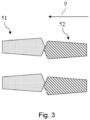
- FIG. 3 schematically illustrates two adjacent teeth of the input-side engagement component 51 with two adjacent teeth of the output-side engagement component 52.
- the rotational speed difference between the output-side engagement component 52 and the input-side engagement component 51 is set to a preset value, the absolute value of which is within the range of 10 rpm to 30 rpm. That is, the completion of speed adjustment is not judged merely by whether the rotational speed difference is within a defined range, but by whether the rotational speed difference is equal to a preset value.
- the rotational speed difference between the output-side engagement component 52 and the input-side engagement component 51 is thereby adjusted to a desired preset value with extreme accuracy upon the completion of speed adjustment, thereby further increasing the success rate of gear engagement.
- the absolute value of the preset value is within the range of 13 rpm to 17 rpm, particularly 15 rpm.
- the optimum value of the preset value can, for example, be determined by means of full-vehicle testing. It is conceivable that in full-vehicle testing, the success rate of gear shifting for different preset values may be determined and an optimal preset value may be selected therefrom.
- the preset value may also be determined based on information related to road conditions.
- the information may comprise the current slope, current surface humidity, current weather, etc. This can further increase the success rate of gear shifting.
- the preset value when the electric vehicle is on an uphill slope, the preset value is set to be greater than when on a level road, and it increases with the increase in uphill gradient; and/or when the electric vehicle is on a downhill slope, the preset value is set to be smaller than when on a level road, and it decreases with the increase in downhill gradient; When going uphill, the steeper the slope, the greater the resistance against the electric vehicle.
- setting the preset value greater than that when on flat roads can actually increase the success rate of gear shifting.
- the resistance against the electric vehicle decreases, and setting the preset value lower than that when on flat roads can increase the success rate of gear shifting.
- the preset value may also be a fixed value. For example, regardless of road conditions, the preset value may always be set to +15 rpm.
- the compensation value is in particular used to compensate for deviations in the rotational speed of the output-side engagement component due to process time, which may comprise the process time from the issuance of a speed adjustment request and the actual execution of the speed adjustment and/or the process time between the execution of the speed adjustment and the actual knowledge that the speed adjustment has been executed.
- B k * ⁇ T, wherein k represents the slope of change of the rotational speed of the output-side engagement component 52 known at time T0, and ⁇ T is one of the following three times or the sum of two or more of the following three times: the communication time from the TCU 1 to the MCU 2, the time for the MCU 2 to execute one step; and the communication time from the MCU 2 to the TCU 1.
- ⁇ T is in particular the sum of the communication time from the TCU 1 to the MCU 2, the time for the MCU 2 to execute one step; and the communication time from the MCU 2 to the TCU 1.
- the compensation value can thus be calculated very accurately.
- other methods for setting the compensation value B are also conceivable, such as setting it to a fixed value.
- the speed adjustment process comprises a judgment step, wherein it is determined whether the speed adjustment has been completed based on whether the preset conditions have been continuously met for a preset time, with the preset conditions comprising at least one of the following:
- the process reliability of the gear shifting method may be effectively improved by the judgment step.
- it is also possible to not perform the judgment step i.e., the TCU 1 issues an engagement command directly after receiving confirmation of speed adjustment execution from the MCU 2.
- the first error range and the second error range are, for example, ⁇ 2 rpm; the preset time is, for example, 20 ms. However, other suitable values may be selected according to the actual situation.
- FIG. 4 schematically illustrates an example of the gear system of the electric drive system.
- the motor shaft 70 of the drive motor 4 is connected to the first shaft 72 via a first speed reduction mechanism 71 for speed reduction of the transmission 5.
- the first shaft 72 is exemplarily secured with two first gears 73, which are constantly engaged with two second gears 75 capable of rotating relative to each other and supported on a second shaft 74.
- the two first gears 73 and the two second gears 75 constitute two different gear ratios or, in other words, two different gear positions.
- the two second gears 75 each have, for example, a ring gear 77 fixed thereto.
- the second shaft 74 is further provided with two bushings 78 that rotate synchronously with the second shaft 74.
- These two bushings 78 may be axially moved relative to the second shaft 74 under the control of the corresponding shifting fork 54.
- the bushing 78 and the ring gear 77 are in a disengaged state. If the left gear position is selected, the left bushing 78 is pushed to the left to engage with the left ring gear 77; if the right gear position is selected, the right bushing 78 is pushed to the left to engage with the right ring gear 77.
- the second shaft 74 is, for example, further connected to the wheel axle via a second speed reduction mechanism 76 used for speed reduction.
- the various components in FIG. 4 should be understood as merely exemplary and should not be construed as restrictive representations.
- the bushing 78 of the transmission 5 directly engages with the ring gear 77 and there is no synchronizer ring between them.
Landscapes
- Engineering & Computer Science (AREA)
- General Engineering & Computer Science (AREA)
- Mechanical Engineering (AREA)
- Power Engineering (AREA)
- Transportation (AREA)
- Control Of Transmission Device (AREA)
- Electric Propulsion And Braking For Vehicles (AREA)
Abstract
Description
- The present application relates to a gear shifting method for use in electric vehicles, a transmission control unit (TCU) for use in electric vehicles, a computer program product, an electric drive system for use in electric vehicles, and an electric vehicle.
- In order to achieve more flexible and convenient adjustment of speed and torque, the electric drive system for electric vehicles is equipped with a transmission capable of shifting gears. However, the current transmission has a limited success rate of gear shifting. To this end, there is a need to provide an improved method of gear shifting for use in electric vehicles.
- The purpose of this application is to provide a gear shifting method for use in electric vehicles that can improve the success rate of gear shifting.
- According to a first aspect of the present application, a gear shifting method for use in electric vehicles is provided, wherein the gear shifting method comprises at least
- a speed adjustment process, wherein a speed adjustment request is issued to adjust the rotational speed of the drive motor of the electric vehicle, ensuring that the absolute rotational speed difference between the output-side engagement component and the input-side engagement component remains within the range of 10 rpm (revolutions per minute) to 30 rpm when the input-side engagement component and the output-side engagement component of the transmission, driven by the drive motor, are disengaged;
- and an engagement process, wherein an engagement command is issued after the completion of the speed adjustment process, so as to engage the input-side engagement component with the output-side engagement component for gear engagement.
- The rotational speed difference between the output-side engagement component and the input-side engagement component should be understood as the rotational speed of the output-side engagement component minus the rotational speed of the input-side engagement component.
- According to one optional example of the present application, during the speed adjustment process, the rotational speed difference between the output-side engagement component and the input-side engagement component is set to a preset value, the absolute value of which is within the range of 10 rpm to 30 rpm.
- According to one optional example of the present application, when the electric vehicle is on a level road, the absolute value of the preset value is within the range of 13 rpm to 17 rpm, particularly 15 rpm.
- According to one optional example of the present application, when the electric vehicle is on an uphill slope, the preset value is set to be greater than when on a level road, and it increases with the increase in uphill gradient.
- According to one optional example of the present application, when the electric vehicle is on a downhill slope, the preset value is set to be smaller than when on a level road, and it decreases with the increase in downhill gradient;
- According to one optional example of the present application, the preset value is a fixed value.
- According to one optional example of the present application, the input-side engagement component and the output-side engagement component are adapted to engage with each other internally;
- According to one optional example of the present application, the input-side engagement component is a ring gear, and the output-side engagement component is a bushing, and during the engagement process, the engagement command causes the shifting fork to move the bushing to engage with the ring gear.
- According to one optional example of the present application, during the speed adjustment process, the requested rotational speed Vm of the drive motor is determined by the following formula:


- According to one optional example of the present application, B = k * ΔT, wherein k represents the slope of change of the rotational speed of the output-side engagement component known at time T0, and ΔT is one of the following three times or the sum of two or more of the following three times: the communication time from the TCU, which controls the transmission of the electric vehicle, to the motor control unit (MCU), which controls the drive motor; the time for the MCU to execute one step; and the communication time from the MCU to the TCU.
- According to one optional example of the present application, the speed adjustment process comprises a judgment step, wherein it is determined whether the speed adjustment has been completed based on whether the preset conditions have been continuously met for the preset time, with the preset conditions comprising at least one of the following:
- the deviation between the actual rotational speed of the input-side engagement component and the target rotational speed Vr is within a first error range;
- the deviation of the rotational speed difference between the actual rotational speed of the output-side engagement component and the actual rotational speed of the input-side engagement component from the preset value is within a second error range.
- According to one optional example of the present application, the first error range and the second error range are ±2 rpm;
- According to one optional example of the present application, the preset time is 20 ms.
- According to a second aspect of the present application, a TCU for use in electric vehicles is provided, wherein the TCU is configured to execute the above gear shifting method.
- According to a third aspect of the present application, a computer program product comprising computer program instructions is provided, wherein when the computer program instructions are executed by one or a plurality of processors, the processors are capable of performing the gear shifting method according to the above gear shifting method.
- According to a fourth aspect of the present application, an electric drive system for use in electric vehicles is provided, characterized in that the electric drive system comprises a drive motor, a transmission, and a TCU.
- According to one optional example of the present application, the electric drive system is an e-axle.
- According to one optional example of the present application, the input-side engagement component of the transmission directly engages with the output-side engagement component and there is no synchronizer ring between them.
- According to one optional example of the present application, the electric drive system comprises an MCU and an inverter for controlling the drive motor.
- According to one optional example of the present application, the electric drive system does not have a clutch.
- According to one optional example of the present application, the electric drive system comprises an input shaft rotational speed sensor for the input shaft and an output shaft rotational speed sensor for the output shaft, wherein the input shaft directly or indirectly drives the input-side engagement component of the transmission, and the output-side engagement component of the transmission directly or indirectly drives the output shaft.
- According to a fourth aspect of the present application, an electric vehicle is provided, wherein comprises the above electric drive system.
- In some examples, the positive effects of the present application are as follows: it can greatly increase the success rate of gear shifting; it eliminates the need for synchronizer rings used in a conventional transmission for assisting in gear engagement.
- The present application is described in greater detail below with reference to the accompanying drawings to provide a better understanding of its principles, features, and advantages. The accompanying drawings include the following:
-
FIG. 1 schematically illustrates, in a flowchart, an example of the entire gear shifting procedure for the electric drive system of an electric vehicle. -
FIG. 2 schematically illustrates an example of a structural diagram of the electric drive system. -
FIG. 3 schematically illustrates two adjacent teeth of the input-side engagement component with two adjacent teeth of the output-side engagement component. -
FIG. 4 schematically illustrates an example of the gear system of the electric drive system. - To provide a clearer understanding of the technical problem, technical solution, and beneficial technical effect addressed by the present application, the following detailed description of the present application is provided with reference to the accompanying drawings and multiple exemplary examples. It should be understood that the specific examples described herein are provided solely for the purpose of explaining the present application and not for limiting the scope of protection of the present application.
- In order to achieve more flexible and convenient adjustment of speed and torque, the electric drive system for electric vehicles is equipped with a transmission capable of shifting gears.
-
FIG. 1 schematically illustrates, in a flowchart, an example of the entire gear shifting procedure for the electric drive system of an electric vehicle. This electric drive system is for example, an e-axle, but other forms of electric drive systems may also be conceived. After receiving a gear shifting request, as shown inFIG. 1 , the entire gear shifting procedure comprises, for example: - torque reduction 801: reducing the torque of the drive motor;
- gear disengagement 802: disengaging the pair of gears of the current gear position of the transmission;
- speed adjustment 803: adjusting the speed of the pair of gears to be engaged in the new gear position;
- gear engagement 804: engaging the pair of gears of the new gear position;
- torque restoration 805: adjusting the torque of the drive motor according to the requirement.
- In the existing speed adjustment, the condition for completion of the speed adjustment is that the rotational speed difference of the pair of gears in the new gear position is within a predetermined range, such as ±50 rpm. The specific value of the rotational speed difference is not of concern here. However, this type of speed adjustment results in a limited success rate during gear engagement, sometimes leading to gear shifting failure and requiring repeated attempts.
-
FIG. 2 schematically illustrates an example of a structural diagram of the electric drive system. - As shown in
FIG. 2 , the electric drive system may comprise, for example, adrive motor 4, atransmission 5, and aTCU 1. The TCU 1 is used to control thetransmission 5. The electric drive system may further comprises anMCU 2 and aninverter 3 for controlling thedrive motor 4; TheMCU 2 is capable of adjusting the rotational speed of thedrive motor 4 through theinverter 3. - According to one exemplary example, the electric drive system does not have a clutch. Unlike the engine of a conventional fuel vehicle, since the rotational speed of the
drive motor 4 can be easily controlled, gear shifting may be facilitated via the direct coordination of thedrive motor 4, thus eliminating the need for a clutch in the electric drive system. However, it is also conceivable that the electric drive system still has a clutch. - The
transmission 5 may comprise, for example, an input-side engagement component 51 and an output-side engagement component 52. When the input-side engagement component 51 engages with the output-side engagement component 52, the gear engagement is completed. - According to one exemplary example, the input-
side engagement component 51 is aring gear 77 and the output-side engagement component 52 is a bushing 78 (seeFIG. 4 ). Thetransmission 5 may in this case may comprise ahydraulic actuator 53 and a shiftingfork 54. During the engagement process, the engagement command causes the shiftingfork 54 to move thebushing 78 to engage with thering gear 77. Depending on the type oftransmission 5, the input-side engagement component 51 and the output-side engagement component 52 may also have other configurations and, accordingly, the input-side engagement component 51 and the output-side engagement component 52 may be engaged in other ways. - According to one exemplary example, the input-
side engagement component 51 and the output-side engagement component 52 are adapted to engage with each other internally. However, depending on the type oftransmission 5, it is also possible for the input-side engagement component 51 and the output-side engagement component to be adapted to engage with each other externally. - The electric drive system may, for example, further comprise an input shaft
rotational speed sensor 61 for the input shaft and an output shaftrotational speed sensor 62 for the output shaft, wherein the input shaft directly or indirectly drives the input-side engagement component 51 of thetransmission 5, and the output-side engagement component 52 of thetransmission 5 directly or indirectly drives the output shaft. TheTCU 1 can obtain the speed of the input-side engagement component 51 based on the input shaft rotational speed collected by the input shaftrotational speed sensor 61, and obtain the speed of the output-side engagement component 52 based on the output shaft speed collected by output shaftrotational speed sensor 62. - The gear shifting method comprises at least
- a speed adjustment process, wherein a speed adjustment request is issued to adjust the rotational speed of the
drive motor 4 of the electric vehicle, ensuring that the absolute rotational speed difference between the output-side engagement component 52 and the input-side engagement component 51 remains within the range of 10 rpm to 30 rpm when the input-side engagement component 51 and the output-side engagement component 52 of thetransmission 5, driven by thedrive motor 4, are disengaged; - and an engagement process, wherein an engagement command is issued after the completion of the speed adjustment process, so as to engage the input-
side engagement component 51 with the output-side engagement component 52 for gear engagement. - By ensuring that the rotational speed difference between the input-
side engagement component 51 and the output-side engagement component 52 is neither too small nor too large, it greatly increases the success rate of gear shifting, and on the other hand, it makes it possible to dispense with the synchronizer rings used in aconventional transmission 5 for assisting in gear engagement. -
FIG. 3 schematically illustrates two adjacent teeth of the input-side engagement component 51 with two adjacent teeth of the output-side engagement component 52. If the rotational speed difference is too small or even equal to zero, as shown inFIG. 3 , it can be seen that when shifting in the direction ofgear engagement 9, the input-side engagement component 51 and the output-side engagement component 52 are likely to rotate synchronously after the initial collision, thus resisting each other and preventing gear engagement. Therefore, to a certain extent, the present application also overcomes the technical bias of "ensuring consistency between the rotational speeds of the input-side engagement component 51 and the output-side engagement component 52 as much as possible" during speed adjustment. If the rotational speed difference is too large, a tooth on the output-side engagement component 52 knocked out of the way by a new tooth of the input-side engagement component 51 before it is fully engaged, thereby resulting in gear engagement failure due to many improper engagements. - According to one exemplary example, during the speed adjustment process, the rotational speed difference between the output-
side engagement component 52 and the input-side engagement component 51 is set to a preset value, the absolute value of which is within the range of 10 rpm to 30 rpm. That is, the completion of speed adjustment is not judged merely by whether the rotational speed difference is within a defined range, but by whether the rotational speed difference is equal to a preset value. The rotational speed difference between the output-side engagement component 52 and the input-side engagement component 51 is thereby adjusted to a desired preset value with extreme accuracy upon the completion of speed adjustment, thereby further increasing the success rate of gear engagement. - According to one exemplary example, when the electric vehicle is on a level road, the absolute value of the preset value is within the range of 13 rpm to 17 rpm, particularly 15 rpm. The optimum value of the preset value can, for example, be determined by means of full-vehicle testing. It is conceivable that in full-vehicle testing, the success rate of gear shifting for different preset values may be determined and an optimal preset value may be selected therefrom.
- The preset value may also be determined based on information related to road conditions. Here, the information may comprise the current slope, current surface humidity, current weather, etc. This can further increase the success rate of gear shifting.
- According to one exemplary example, when the electric vehicle is on an uphill slope, the preset value is set to be greater than when on a level road, and it increases with the increase in uphill gradient; and/or when the electric vehicle is on a downhill slope, the preset value is set to be smaller than when on a level road, and it decreases with the increase in downhill gradient; When going uphill, the steeper the slope, the greater the resistance against the electric vehicle. Here, setting the preset value greater than that when on flat roads can actually increase the success rate of gear shifting. When going downhill, the resistance against the electric vehicle decreases, and setting the preset value lower than that when on flat roads can increase the success rate of gear shifting.
- Alternatively, the preset value may also be a fixed value. For example, regardless of road conditions, the preset value may always be set to +15 rpm.
- According to one exemplary example, during the speed adjustment process, the requested rotational speed Vm of the drive motor is determined by the following formula:


side engagement component 51, A denotes the preset value, B denotes the compensation value, and i denotes the transmission ratio from thedrive motor 4 to the input-side engagement component 51. The compensation value is in particular used to compensate for deviations in the rotational speed of the output-side engagement component due to process time, which may comprise the process time from the issuance of a speed adjustment request and the actual execution of the speed adjustment and/or the process time between the execution of the speed adjustment and the actual knowledge that the speed adjustment has been executed. - According to one exemplary example, B = k * ΔT, wherein k represents the slope of change of the rotational speed of the output-
side engagement component 52 known at time T0, and ΔT is one of the following three times or the sum of two or more of the following three times: the communication time from theTCU 1 to theMCU 2, the time for theMCU 2 to execute one step; and the communication time from theMCU 2 to theTCU 1. ΔT is in particular the sum of the communication time from theTCU 1 to theMCU 2, the time for theMCU 2 to execute one step; and the communication time from theMCU 2 to theTCU 1. The compensation value can thus be calculated very accurately. However, other methods for setting the compensation value B are also conceivable, such as setting it to a fixed value. - Here, an illustrative example is provided to demonstrate how to calculate the requested speed Vm of the drive motor 4:
- Assuming that through full-vehicle testing, it is determined that the success rate of gear shifting is highest when the rotational speed difference between the output-
side engagement component 52 and the input-side engagement component 51 is +15 rpm, i.e., when the bushing is 15 rpm faster than the ring gear, the preset value A may be set to 15 rpm; - In the speed adjustment process, assuming that at the moment T0 when the speed adjustment request is issued, the actual measured speed Vs0 of the bushing is 500 rpm, and the obtained change rate of the ring gear's rotational speed k is 0.2, and that the communication time from the
TCU 1 to theMCU 2, the time for theMCU 2 to execute one step, and the communication time from theMCU 2 to theTCU 1 are typically fixed values, for example, 10 ms each, the compensation value B may thus be calculated as B = k * ΔT = 0.2 * (10 + 10 + 10) = 6 rpm, and the target speed of the ring gear is hence Vr = Vs0 - A - B = 500 - 15-6 = 479 rpm. The drive ratio i is known and in this case is, for example, 5. The requested rotational speed of thedrive motor 4 Vm = Vr * i = 479 * 5 = 2,395 rpm. - According to one exemplary example, the speed adjustment process comprises a judgment step, wherein it is determined whether the speed adjustment has been completed based on whether the preset conditions have been continuously met for a preset time, with the preset conditions comprising at least one of the following:
- the deviation between the actual rotational speed of the input-
side engagement component 51 and the target rotational speed Vr is within a first error range; - the deviation of the rotational speed difference between the actual rotational speed of the output-
side engagement component 52 and the actual rotational speed of the input-side engagement component 51 from the preset value is within a second error range. - The process reliability of the gear shifting method may be effectively improved by the judgment step. However, it is also possible to not perform the judgment step, i.e., the
TCU 1 issues an engagement command directly after receiving confirmation of speed adjustment execution from theMCU 2. - The first error range and the second error range are, for example, ±2 rpm; the preset time is, for example, 20 ms. However, other suitable values may be selected according to the actual situation.
-
FIG. 4 schematically illustrates an example of the gear system of the electric drive system. - As can be seen in
FIG. 4 , themotor shaft 70 of thedrive motor 4 is connected to thefirst shaft 72 via a firstspeed reduction mechanism 71 for speed reduction of thetransmission 5. Thefirst shaft 72 is exemplarily secured with twofirst gears 73, which are constantly engaged with twosecond gears 75 capable of rotating relative to each other and supported on asecond shaft 74. The twofirst gears 73 and the twosecond gears 75 constitute two different gear ratios or, in other words, two different gear positions. The twosecond gears 75 each have, for example, aring gear 77 fixed thereto. Thesecond shaft 74 is further provided with twobushings 78 that rotate synchronously with thesecond shaft 74. These twobushings 78 may be axially moved relative to thesecond shaft 74 under the control of the corresponding shiftingfork 54. InFIG. 4 , thebushing 78 and thering gear 77 are in a disengaged state. If the left gear position is selected, theleft bushing 78 is pushed to the left to engage with theleft ring gear 77; if the right gear position is selected, theright bushing 78 is pushed to the left to engage with theright ring gear 77. Thesecond shaft 74 is, for example, further connected to the wheel axle via a secondspeed reduction mechanism 76 used for speed reduction. Clearly, the various components inFIG. 4 , as well as their quantity and relative positional relationships, should be understood as merely exemplary and should not be construed as restrictive representations. - According to one exemplary example, as shown in
FIG. 4 , thebushing 78 of thetransmission 5 directly engages with thering gear 77 and there is no synchronizer ring between them. - In conjunction with
FIG. 2 andFIG. 4 , an example of a more specific gear shifting procedure is as follows: - a gear shifting request is received;
- the
MCU 2 reduces the torque of thedrive motor 4 via theinverter 3; - the
TCU 1 controls thehydraulic actuator 53 to move the shiftingfork 54 of the current gear position, causing thebushing 78 of the current gear position to disengage from thering gear 77; - The
TCU 1 calculates the speed Vs0 of thebushing 78 of the new gear position based on the output shaft rotational speed collected by the output shaft sensor, and determines, in particular, the preset value A based on the current slope, as well as calculates the compensation value B, and finally calculates, by means of these, the target speed Vr of thering gear 77 of the new gear position and the required drive motor rotational speed Vm to be requested from theMCU 2; - after receiving the request from the
TCU 1, theMCU 2 adjusts the rotational speed of thedrive motor 4 to the requested drive motor rotational speed Vm via theinverter 3 and notifies theTCU 1; - the
TCU 1 executes the judgment step after receiving the notification; - after determining the completion of the speed adjustment through the judgment step, the
TCU 1 controls thehydraulic actuator 53 to move the shiftingfork 54 of the new gear position, causing thebushing 78 of the new gear position to engage with thering gear 77, thereby completing the gear engagement; - the
MCU 2 adjusts thedrive motor 4 to the target torque via theinverter 3; - For the mentioned numerical ranges, it should be understood that the present application discloses examples that include both the boundary values of the numerical range and at least partially cover them, as well as examples where the boundary values of the numerical range are not included. The terms "first" and "second" are intended only to avoid conflation of elements and are not related to the quantity or importance of the elements. "For use in electric vehicles" should be understood as "may be used" rather than "may only be used". Clearly, the gear shifting method, TCU, and electric drive system of the present application may also be applicable to other electric transportation vehicles.
- Although specific embodiments of the present application have been described in detail here, they are provided solely for explanatory purposes and should not be construed as limiting the scope of the present application. Various substitutions, alterations, and modifications may be conceived without departing from the spirit and scope of the present application. The various typical examples and examples cited in the present application may be freely combined with each another, without limitation to the descriptions in the Specification, under non-contradictory circumstances.
-
- 1
- Transmission control unit
- -2
- Motor control unit
- -3
- Inverter
- 4
- Drive motor
- 5
- Transmission
- 51
- Input-side engagement component
- 52
- Output-side engagement component
- 53
- Hydraulic actuator
- 54
- Shifting fork
- 61
- Input shaft rotational speed sensor
- 62
- Output shaft rotational speed sensor
- 70
- Motor shaft
- 71
- First speed reduction mechanism
- 72
- First axle
- 73
- First gear
- 74
- Second shaft
- 75
- Second gear
- 76
- Second speed reduction mechanism
- 77
- Ring gear
- 78
- Bushing
- 801
- Torque reduction
- 802
- Gear disengagement
- 803
- Speed adjustment
- 804
- Gear engagement
- 805
- Torque restoration
- 9
- Direction of gear engagement
Claims (16)
- A gear shifting method for use in electric vehicles, characterized in that the gear shifting method at least comprises:a speed adjustment process, wherein a speed adjustment request is issued to adjust the rotational speed of the drive motor of the electric vehicle (4), ensuring that the absolute rotational speed difference between the output-side engagement component (52) and the input-side engagement component (51) remains within the range of 10 rpm to 30 rpm when the input-side engagement component (51) and the output-side engagement component (52) of the transmission (5), driven by the drive motor (4), are disengaged;and an engagement process, wherein an engagement command is issued after the completion of the speed adjustment process, so as to engage the input-side engagement component (51) with the output-side engagement component (52) for gear engagement.
- The gear shifting method according to Claim 1, characterized in that, during the speed adjustment process, the rotational speed difference between the output-side engagement component (52) and the input-side engagement component (51) is set to a preset value, the absolute value of which is within the range of 10 rpm to 30 rpm.
- The gear shifting method according to Claim 2, characterized in that, when the electric vehicle is on a level road, the absolute value of the preset value is within the range of 13 rpm to 17 rpm, particularly 15 rpm.
- The gear shifting method according to Claim 2 or 3, characterized in that the gear shifting method comprises at least one of the following features:when the electric vehicle is on an uphill slope, the preset value is set to be greater than when on a level road, and it increases with the increase in uphill gradient;when the electric vehicle is on a downhill slope, the preset value is set to be smaller than when on a level road, and it decreases with the increase in downhill gradient;
- The gear shifting method according to Claim 2 or 3, characterized in that the preset value is a fixed value.
- The gear shifting method according to any one of Claims 1 to 3, characterized in that the gear shifting method comprises at least one of the following features:the input-side engagement component (51) and the output-side engagement component (52) are adapted to engage with each other internally;the input-side engagement component (51) is a ring gear (77), and the output-side engagement component (52) is a bushing (78), and during the engagement process, the engagement command causes the shifting fork (54) to move the bushing (78) to engage with the ring gear (77).
- The gear shifting method according to Claim 2 or 3, characterized in that, during the speed adjustment process, the requested rotational speed Vm of the drive motor (4) is determined by the following formula:


- The gear shifting method according to Claim 7, characterized in that B = k * ΔT, wherein k represents the slope of change of the rotational speed of the output-side engagement component (52) known at time T0, and ΔT is one of the following three times or the sum of two or more of the following three times: the communication time from the transmission control unit (1), which controls the transmission (5) of the electric vehicle, to the motor control unit (2), which controls the drive motor (4); the time for the motor control unit (2) to execute one step; and the communication time from the motor control unit (2) to the transmission control unit (1).
- The gear shifting method according to Claim 7, characterized in that the speed adjustment process comprises a judgment step, wherein it is determined whether the speed adjustment has been completed based on whether the preset conditions have been continuously met for a preset time, with the preset conditions comprising at least one of the following:the deviation between the actual rotational speed of the input-side engagement component (51) and the target rotational speed Vr is within a first error range;the deviation of the rotational speed difference between the actual rotational speed of the output-side engagement component (52) and the actual rotational speed of the input-side engagement component (51) from the preset value is within a second error range.
- The gear shifting method according to Claim 9, characterized in that the gear shifting method comprises at least one of the following features:the first error range and the second error range are ±2 rpm;The preset time is 20 ms.
- A transmission control unit (1) for use in electric vehicles, characterized in that the transmission control unit (1) is configured to execute the gear shifting method according to any one of Claims 1 to 10.
- A computer program product comprising computer program instructions, wherein when the computer program instructions are executed by one or a plurality of processors, the processors are capable of performing the gear shifting method according to any one of Claims 1 to 10.
- An electric drive system for use in electric vehicles, characterized in that the electric drive system comprises a drive motor (4), a transmission (5), and a transmission control unit (1) according to Claim 11.
- The electric drive system according to Claim 13, characterized in that the electric drive system comprises at least one of the following features:the electric drive system is an e-axle;the input-side engagement component (51) of the transmission (5) directly engages with the output-side engagement component (52) and there is no synchronizer ring between them;the electric drive system comprises a motor control unit (2) and an inverter (3) for controlling the drive motor (4);the electric drive system does not have a clutch.
- The electric drive system according to Claim 13 or 14, characterized in that the electric drive system comprises an input shaft rotational speed sensor (61) for the input shaft and an output shaft rotational speed sensor (62) for the output shaft, wherein the input shaft directly or indirectly drives the input-side engagement component (51) of the transmission (5), and the output-side engagement component (52) of the transmission (5) directly or indirectly drives the output shaft.
- An electric vehicle, characterized in that the electric vehicle comprises an electric drive system according to any one of Claims 13 to 15.
Applications Claiming Priority (1)
| Application Number | Priority Date | Filing Date | Title |
|---|---|---|---|
| CN202310618099.0A CN119042312A (en) | 2023-05-29 | 2023-05-29 | Gear shifting method, control unit, program product, electric drive system and electric vehicle |
Publications (2)
| Publication Number | Publication Date |
|---|---|
| EP4471296A1 true EP4471296A1 (en) | 2024-12-04 |
| EP4471296B1 EP4471296B1 (en) | 2026-03-04 |
Family
ID=90924147
Family Applications (1)
| Application Number | Title | Priority Date | Filing Date |
|---|---|---|---|
| EP24172963.1A Active EP4471296B1 (en) | 2023-05-29 | 2024-04-29 | A gear shifting method, control unit, program product, electric drive system, and electric vehicle |
Country Status (3)
| Country | Link |
|---|---|
| US (1) | US12570160B2 (en) |
| EP (1) | EP4471296B1 (en) |
| CN (1) | CN119042312A (en) |
Citations (4)
| Publication number | Priority date | Publication date | Assignee | Title |
|---|---|---|---|---|
| DE102006003715A1 (en) * | 2006-01-26 | 2007-08-02 | Zf Friedrichshafen Ag | Synchronizing automated gearbox with matching to input revolution rate involves controlling additional electrical machine, optionally main drive motor, so input revolution rate to be adjusted with drive gear engaged has desired time profile |
| WO2011076485A1 (en) * | 2009-12-23 | 2011-06-30 | Robert Bosch Gmbh | Method and device for determining desired torque for controlling an electric machine of a motor vehicle |
| US20160075337A1 (en) * | 2013-04-17 | 2016-03-17 | Renault S.A.S. | Method for controlling the claw coupling of a gearbox |
| CN112930452B (en) * | 2018-10-02 | 2022-07-12 | 戴姆勒股份公司 | Method for operating a dual clutch transmission to release the corresponding top gear position |
Family Cites Families (4)
| Publication number | Priority date | Publication date | Assignee | Title |
|---|---|---|---|---|
| DE19530233A1 (en) * | 1995-08-17 | 1997-02-20 | Audi Ag | Hybrid drive transmission for vehicle |
| JP3345576B2 (en) * | 1998-01-08 | 2002-11-18 | モトール自動車株式会社 | Speed change control device for prime mover |
| JP2014105826A (en) * | 2012-11-29 | 2014-06-09 | Fuji Heavy Ind Ltd | Clutch control device |
| CN110177960B (en) * | 2016-12-22 | 2022-10-25 | 伊顿康明斯自动传输技术有限责任公司 | High-efficiency high-output transmission |
-
2023
- 2023-05-29 CN CN202310618099.0A patent/CN119042312A/en active Pending
-
2024
- 2024-04-29 EP EP24172963.1A patent/EP4471296B1/en active Active
- 2024-05-23 US US18/672,548 patent/US12570160B2/en active Active
Patent Citations (4)
| Publication number | Priority date | Publication date | Assignee | Title |
|---|---|---|---|---|
| DE102006003715A1 (en) * | 2006-01-26 | 2007-08-02 | Zf Friedrichshafen Ag | Synchronizing automated gearbox with matching to input revolution rate involves controlling additional electrical machine, optionally main drive motor, so input revolution rate to be adjusted with drive gear engaged has desired time profile |
| WO2011076485A1 (en) * | 2009-12-23 | 2011-06-30 | Robert Bosch Gmbh | Method and device for determining desired torque for controlling an electric machine of a motor vehicle |
| US20160075337A1 (en) * | 2013-04-17 | 2016-03-17 | Renault S.A.S. | Method for controlling the claw coupling of a gearbox |
| CN112930452B (en) * | 2018-10-02 | 2022-07-12 | 戴姆勒股份公司 | Method for operating a dual clutch transmission to release the corresponding top gear position |
Also Published As
| Publication number | Publication date |
|---|---|
| US12570160B2 (en) | 2026-03-10 |
| US20240399893A1 (en) | 2024-12-05 |
| EP4471296B1 (en) | 2026-03-04 |
| CN119042312A (en) | 2024-11-29 |
Similar Documents
| Publication | Publication Date | Title |
|---|---|---|
| CN102287530B (en) | The method of control upshift in vehicle transmission | |
| JPH0315384Y2 (en) | ||
| EP0635391B1 (en) | Touch point identification algorithm for automatic clutch controller | |
| CN105840808B (en) | Shift coordination control method for wet dual-clutch automatic transmission | |
| US8070652B2 (en) | Method for overcoming tooth butt conditions when engaging gears in transmissions | |
| US7367924B2 (en) | Method for controlling gear-shifting processes of a powershift gearbox and corresponding powershift gearbox | |
| US8260513B2 (en) | Producing vehicle creep through a transmission without a torque converter | |
| US8849529B2 (en) | Method and system for determining the contact point for a clutch in a vehicle | |
| US20090069992A1 (en) | Method and device for adapting the control of the clutches of a double clutch transmission | |
| CN105276161B (en) | The transmission system for a little learning logic is stung with clutch | |
| EP0787619B1 (en) | Process for correction of engine torque during gear changes | |
| EP4711644A1 (en) | Pure electric multi-gear amt gear-shifting control method, drivetrain, and electric vehicle | |
| US7367917B2 (en) | Shift change control system and automatic transmission system of automobile | |
| US20150051799A1 (en) | Method for synchronizing a gear on a gearbox shaft | |
| CN104019221A (en) | Downshift controls using measured output torque | |
| DE102014214782A1 (en) | METHOD FOR OPERATING A GEARBOX | |
| JP2004270944A (en) | Control method of clutch | |
| US12570160B2 (en) | Gear shifting method, control unit, program product, electric drive system, and electric vehicle | |
| WO2008065922A1 (en) | Shifting time control device for vehicular power transmission system | |
| US20040138800A1 (en) | Transmission systems | |
| CN114251445A (en) | Vehicle gear shifting control method and device | |
| CN106838295B (en) | Manual transmission clutch control using driveline measurements | |
| EP0993388B1 (en) | Method of gear changing in a motor vehicle | |
| JPS6034562A (en) | Gear shifting control method for automatic transmission | |
| JP2014126114A (en) | Control device for automatic transmission |
Legal Events
| Date | Code | Title | Description |
|---|---|---|---|
| PUAI | Public reference made under article 153(3) epc to a published international application that has entered the european phase |
Free format text: ORIGINAL CODE: 0009012 |
|
| STAA | Information on the status of an ep patent application or granted ep patent |
Free format text: STATUS: THE APPLICATION HAS BEEN PUBLISHED |
|
| AK | Designated contracting states |
Kind code of ref document: A1 Designated state(s): AL AT BE BG CH CY CZ DE DK EE ES FI FR GB GR HR HU IE IS IT LI LT LU LV MC ME MK MT NL NO PL PT RO RS SE SI SK SM TR |
|
| STAA | Information on the status of an ep patent application or granted ep patent |
Free format text: STATUS: REQUEST FOR EXAMINATION WAS MADE |
|
| 17P | Request for examination filed |
Effective date: 20250604 |
|
| GRAP | Despatch of communication of intention to grant a patent |
Free format text: ORIGINAL CODE: EPIDOSNIGR1 |
|
| STAA | Information on the status of an ep patent application or granted ep patent |
Free format text: STATUS: GRANT OF PATENT IS INTENDED |
|
| RIC1 | Information provided on ipc code assigned before grant |
Ipc: F16H 59/46 20060101AFI20250829BHEP Ipc: F16H 61/04 20060101ALI20250829BHEP Ipc: B60K 1/00 20060101ALN20250829BHEP |
|
| INTG | Intention to grant announced |
Effective date: 20251007 |
|
| RIC1 | Information provided on ipc code assigned before grant |
Ipc: F16H 59/46 20060101AFI20250929BHEP Ipc: F16H 61/04 20060101ALI20250929BHEP Ipc: B60K 1/00 20060101ALN20250929BHEP |
|
| GRAS | Grant fee paid |
Free format text: ORIGINAL CODE: EPIDOSNIGR3 |
|
| GRAA | (expected) grant |
Free format text: ORIGINAL CODE: 0009210 |
|
| STAA | Information on the status of an ep patent application or granted ep patent |
Free format text: STATUS: THE PATENT HAS BEEN GRANTED |
|
| AK | Designated contracting states |
Kind code of ref document: B1 Designated state(s): AL AT BE BG CH CY CZ DE DK EE ES FI FR GB GR HR HU IE IS IT LI LT LU LV MC ME MK MT NL NO PL PT RO RS SE SI SK SM TR |
|
| REG | Reference to a national code |
Ref country code: CH Ref legal event code: F10 Free format text: ST27 STATUS EVENT CODE: U-0-0-F10-F00 (AS PROVIDED BY THE NATIONAL OFFICE) Effective date: 20260304 Ref country code: GB Ref legal event code: FG4D |
|
| REG | Reference to a national code |
Ref country code: IE Ref legal event code: FG4D |
|
| REG | Reference to a national code |
Ref country code: DE Ref legal event code: R096 Ref document number: 602024002917 Country of ref document: DE |