EP4471293A1 - Left-right wheel drive device - Google Patents
Left-right wheel drive device Download PDFInfo
- Publication number
- EP4471293A1 EP4471293A1 EP22924119.5A EP22924119A EP4471293A1 EP 4471293 A1 EP4471293 A1 EP 4471293A1 EP 22924119 A EP22924119 A EP 22924119A EP 4471293 A1 EP4471293 A1 EP 4471293A1
- Authority
- EP
- European Patent Office
- Prior art keywords
- output shaft
- drive device
- gear
- counter
- fixed
- Prior art date
- Legal status (The legal status is an assumption and is not a legal conclusion. Google has not performed a legal analysis and makes no representation as to the accuracy of the status listed.)
- Pending
Links
Images



Classifications
-
- F—MECHANICAL ENGINEERING; LIGHTING; HEATING; WEAPONS; BLASTING
- F16—ENGINEERING ELEMENTS AND UNITS; GENERAL MEASURES FOR PRODUCING AND MAINTAINING EFFECTIVE FUNCTIONING OF MACHINES OR INSTALLATIONS; THERMAL INSULATION IN GENERAL
- F16H—GEARING
- F16H57/00—General details of gearing
- F16H57/0018—Shaft assemblies for gearings
- F16H57/0037—Special features of coaxial shafts, e.g. relative support thereof
-
- B—PERFORMING OPERATIONS; TRANSPORTING
- B60—VEHICLES IN GENERAL
- B60K—ARRANGEMENT OR MOUNTING OF PROPULSION UNITS OR OF TRANSMISSIONS IN VEHICLES; ARRANGEMENT OR MOUNTING OF PLURAL DIVERSE PRIME-MOVERS IN VEHICLES; AUXILIARY DRIVES FOR VEHICLES; INSTRUMENTATION OR DASHBOARDS FOR VEHICLES; ARRANGEMENTS IN CONNECTION WITH COOLING, AIR INTAKE, GAS EXHAUST OR FUEL SUPPLY OF PROPULSION UNITS IN VEHICLES
- B60K17/00—Arrangement or mounting of transmissions in vehicles
- B60K17/04—Arrangement or mounting of transmissions in vehicles characterised by arrangement, location or kind of gearing
- B60K17/043—Transmission unit disposed in on near the vehicle wheel, or between the differential gear unit and the wheel
-
- B—PERFORMING OPERATIONS; TRANSPORTING
- B60—VEHICLES IN GENERAL
- B60K—ARRANGEMENT OR MOUNTING OF PROPULSION UNITS OR OF TRANSMISSIONS IN VEHICLES; ARRANGEMENT OR MOUNTING OF PLURAL DIVERSE PRIME-MOVERS IN VEHICLES; AUXILIARY DRIVES FOR VEHICLES; INSTRUMENTATION OR DASHBOARDS FOR VEHICLES; ARRANGEMENTS IN CONNECTION WITH COOLING, AIR INTAKE, GAS EXHAUST OR FUEL SUPPLY OF PROPULSION UNITS IN VEHICLES
- B60K17/00—Arrangement or mounting of transmissions in vehicles
- B60K17/04—Arrangement or mounting of transmissions in vehicles characterised by arrangement, location or kind of gearing
- B60K17/043—Transmission unit disposed in on near the vehicle wheel, or between the differential gear unit and the wheel
- B60K17/046—Transmission unit disposed in on near the vehicle wheel, or between the differential gear unit and the wheel with planetary gearing having orbital motion
-
- B—PERFORMING OPERATIONS; TRANSPORTING
- B60—VEHICLES IN GENERAL
- B60K—ARRANGEMENT OR MOUNTING OF PROPULSION UNITS OR OF TRANSMISSIONS IN VEHICLES; ARRANGEMENT OR MOUNTING OF PLURAL DIVERSE PRIME-MOVERS IN VEHICLES; AUXILIARY DRIVES FOR VEHICLES; INSTRUMENTATION OR DASHBOARDS FOR VEHICLES; ARRANGEMENTS IN CONNECTION WITH COOLING, AIR INTAKE, GAS EXHAUST OR FUEL SUPPLY OF PROPULSION UNITS IN VEHICLES
- B60K17/00—Arrangement or mounting of transmissions in vehicles
- B60K17/04—Arrangement or mounting of transmissions in vehicles characterised by arrangement, location or kind of gearing
- B60K17/16—Arrangement or mounting of transmissions in vehicles characterised by arrangement, location or kind of gearing of differential gearing
-
- B—PERFORMING OPERATIONS; TRANSPORTING
- B60—VEHICLES IN GENERAL
- B60K—ARRANGEMENT OR MOUNTING OF PROPULSION UNITS OR OF TRANSMISSIONS IN VEHICLES; ARRANGEMENT OR MOUNTING OF PLURAL DIVERSE PRIME-MOVERS IN VEHICLES; AUXILIARY DRIVES FOR VEHICLES; INSTRUMENTATION OR DASHBOARDS FOR VEHICLES; ARRANGEMENTS IN CONNECTION WITH COOLING, AIR INTAKE, GAS EXHAUST OR FUEL SUPPLY OF PROPULSION UNITS IN VEHICLES
- B60K17/00—Arrangement or mounting of transmissions in vehicles
- B60K17/04—Arrangement or mounting of transmissions in vehicles characterised by arrangement, location or kind of gearing
- B60K17/16—Arrangement or mounting of transmissions in vehicles characterised by arrangement, location or kind of gearing of differential gearing
- B60K17/165—Arrangement or mounting of transmissions in vehicles characterised by arrangement, location or kind of gearing of differential gearing provided between independent half axles
-
- B—PERFORMING OPERATIONS; TRANSPORTING
- B60—VEHICLES IN GENERAL
- B60K—ARRANGEMENT OR MOUNTING OF PROPULSION UNITS OR OF TRANSMISSIONS IN VEHICLES; ARRANGEMENT OR MOUNTING OF PLURAL DIVERSE PRIME-MOVERS IN VEHICLES; AUXILIARY DRIVES FOR VEHICLES; INSTRUMENTATION OR DASHBOARDS FOR VEHICLES; ARRANGEMENTS IN CONNECTION WITH COOLING, AIR INTAKE, GAS EXHAUST OR FUEL SUPPLY OF PROPULSION UNITS IN VEHICLES
- B60K7/00—Disposition of motor in, or adjacent to, traction wheel
-
- B—PERFORMING OPERATIONS; TRANSPORTING
- B60—VEHICLES IN GENERAL
- B60K—ARRANGEMENT OR MOUNTING OF PROPULSION UNITS OR OF TRANSMISSIONS IN VEHICLES; ARRANGEMENT OR MOUNTING OF PLURAL DIVERSE PRIME-MOVERS IN VEHICLES; AUXILIARY DRIVES FOR VEHICLES; INSTRUMENTATION OR DASHBOARDS FOR VEHICLES; ARRANGEMENTS IN CONNECTION WITH COOLING, AIR INTAKE, GAS EXHAUST OR FUEL SUPPLY OF PROPULSION UNITS IN VEHICLES
- B60K7/00—Disposition of motor in, or adjacent to, traction wheel
- B60K7/0007—Disposition of motor in, or adjacent to, traction wheel the motor being electric
-
- F—MECHANICAL ENGINEERING; LIGHTING; HEATING; WEAPONS; BLASTING
- F16—ENGINEERING ELEMENTS AND UNITS; GENERAL MEASURES FOR PRODUCING AND MAINTAINING EFFECTIVE FUNCTIONING OF MACHINES OR INSTALLATIONS; THERMAL INSULATION IN GENERAL
- F16H—GEARING
- F16H48/00—Differential gearings
- F16H48/05—Multiple interconnected differential sets
-
- F—MECHANICAL ENGINEERING; LIGHTING; HEATING; WEAPONS; BLASTING
- F16—ENGINEERING ELEMENTS AND UNITS; GENERAL MEASURES FOR PRODUCING AND MAINTAINING EFFECTIVE FUNCTIONING OF MACHINES OR INSTALLATIONS; THERMAL INSULATION IN GENERAL
- F16H—GEARING
- F16H48/00—Differential gearings
- F16H48/06—Differential gearings with gears having orbital motion
-
- F—MECHANICAL ENGINEERING; LIGHTING; HEATING; WEAPONS; BLASTING
- F16—ENGINEERING ELEMENTS AND UNITS; GENERAL MEASURES FOR PRODUCING AND MAINTAINING EFFECTIVE FUNCTIONING OF MACHINES OR INSTALLATIONS; THERMAL INSULATION IN GENERAL
- F16H—GEARING
- F16H57/00—General details of gearing
- F16H57/02—Gearboxes; Mounting gearing therein
- F16H57/021—Shaft support structures, e.g. partition walls, bearing eyes, casing walls or covers with bearings
-
- F—MECHANICAL ENGINEERING; LIGHTING; HEATING; WEAPONS; BLASTING
- F16—ENGINEERING ELEMENTS AND UNITS; GENERAL MEASURES FOR PRODUCING AND MAINTAINING EFFECTIVE FUNCTIONING OF MACHINES OR INSTALLATIONS; THERMAL INSULATION IN GENERAL
- F16H—GEARING
- F16H57/00—General details of gearing
- F16H57/04—Features relating to lubrication or cooling or heating
- F16H57/048—Type of gearings to be lubricated, cooled or heated
- F16H57/0482—Gearings with gears having orbital motion
- F16H57/0483—Axle or inter-axle differentials
-
- B—PERFORMING OPERATIONS; TRANSPORTING
- B60—VEHICLES IN GENERAL
- B60K—ARRANGEMENT OR MOUNTING OF PROPULSION UNITS OR OF TRANSMISSIONS IN VEHICLES; ARRANGEMENT OR MOUNTING OF PLURAL DIVERSE PRIME-MOVERS IN VEHICLES; AUXILIARY DRIVES FOR VEHICLES; INSTRUMENTATION OR DASHBOARDS FOR VEHICLES; ARRANGEMENTS IN CONNECTION WITH COOLING, AIR INTAKE, GAS EXHAUST OR FUEL SUPPLY OF PROPULSION UNITS IN VEHICLES
- B60K1/00—Arrangement or mounting of electrical propulsion units
- B60K1/02—Arrangement or mounting of electrical propulsion units comprising more than one electric motor
-
- B—PERFORMING OPERATIONS; TRANSPORTING
- B60—VEHICLES IN GENERAL
- B60K—ARRANGEMENT OR MOUNTING OF PROPULSION UNITS OR OF TRANSMISSIONS IN VEHICLES; ARRANGEMENT OR MOUNTING OF PLURAL DIVERSE PRIME-MOVERS IN VEHICLES; AUXILIARY DRIVES FOR VEHICLES; INSTRUMENTATION OR DASHBOARDS FOR VEHICLES; ARRANGEMENTS IN CONNECTION WITH COOLING, AIR INTAKE, GAS EXHAUST OR FUEL SUPPLY OF PROPULSION UNITS IN VEHICLES
- B60K7/00—Disposition of motor in, or adjacent to, traction wheel
- B60K2007/0061—Disposition of motor in, or adjacent to, traction wheel the motor axle being parallel to the wheel axle
-
- F—MECHANICAL ENGINEERING; LIGHTING; HEATING; WEAPONS; BLASTING
- F16—ENGINEERING ELEMENTS AND UNITS; GENERAL MEASURES FOR PRODUCING AND MAINTAINING EFFECTIVE FUNCTIONING OF MACHINES OR INSTALLATIONS; THERMAL INSULATION IN GENERAL
- F16H—GEARING
- F16H1/00—Toothed gearings for conveying rotary motion
- F16H1/02—Toothed gearings for conveying rotary motion without gears having orbital motion
- F16H1/04—Toothed gearings for conveying rotary motion without gears having orbital motion involving only two intermeshing members
- F16H1/06—Toothed gearings for conveying rotary motion without gears having orbital motion involving only two intermeshing members with parallel axes
-
- F—MECHANICAL ENGINEERING; LIGHTING; HEATING; WEAPONS; BLASTING
- F16—ENGINEERING ELEMENTS AND UNITS; GENERAL MEASURES FOR PRODUCING AND MAINTAINING EFFECTIVE FUNCTIONING OF MACHINES OR INSTALLATIONS; THERMAL INSULATION IN GENERAL
- F16H—GEARING
- F16H48/00—Differential gearings
- F16H48/06—Differential gearings with gears having orbital motion
- F16H48/10—Differential gearings with gears having orbital motion with orbital spur gears
- F16H2048/106—Differential gearings with gears having orbital motion with orbital spur gears characterised by two sun gears
-
- F—MECHANICAL ENGINEERING; LIGHTING; HEATING; WEAPONS; BLASTING
- F16—ENGINEERING ELEMENTS AND UNITS; GENERAL MEASURES FOR PRODUCING AND MAINTAINING EFFECTIVE FUNCTIONING OF MACHINES OR INSTALLATIONS; THERMAL INSULATION IN GENERAL
- F16H—GEARING
- F16H57/00—General details of gearing
- F16H57/04—Features relating to lubrication or cooling or heating
- F16H57/0467—Elements of gearings to be lubricated, cooled or heated
- F16H57/0469—Bearings or seals
- F16H57/0471—Bearing
Definitions
- the present invention relates to a left-right wheel drive device that accommodates, in a casing, two electric motors that drive a vehicle and a planetary gear mechanism that amplifies a torque difference between the two electric motors and transmits torques to left and right wheels.
- a vehicle which is provided with a drive device including a planetary gear mechanism that, when driving torques from two independent electric motors (hereinafter also referred to as “motors") are transmitted to left and right driving wheels, amplifies a difference (torque difference) between the two driving torques and transmits the amplified torques.
- motors two independent electric motors
- the presence of such a planetary gear mechanism brings an advantage that can provide a large torque difference to the left and right wheels but also a disadvantage that increases the size of the overall drive device.
- Patent Document 1 WO2021/039966
- FIG. 6 of Patent Document 1 discloses a configuration in which a left end portion of a long second output member (output shaft) on the left side in the drawing is supported by a ball bearing, but does not disclose a supporting structure on one end side of the second output member.
- the space around the one end side of the second output member is narrow because a second coupling member and a second coupling shaft are arranged.
- the one end side of the second output member is rotatably supported by a slide baring (metal), which can be arranged in a narrow space.
- a friction difference occurs due to a difference in the supporting structure.
- Such a friction difference generates a difference in the transfer ratio between the left and right output shafts, which leads to a difference in the left and right turning properties.
- one of the objects of the present invention is to ensure the stability in running straight and the equality in turning left and right without generating a friction difference between two supporting portions on a long output shaft in a left-right wheel drive device that accommodates, in a casing, two electric motors and a planetary gear mechanism.
- an advantageous effect that is derived from each configuration shown in the following detailed modes to carry out the present invention and which is not obtained by the conventional technique can be regarded as another object of the present disclosure.
- the disclosed left-right wheel drive device can be implemented as an embodiment or application example disclosed below, and solves at least a part of the above problem.
- the disclosed left-right wheel drive device is one that accommodates, in a casing, two electric motors that drive a vehicle and a planetary gear mechanism that amplifies a torque difference between the two electric motors and transmits torques to left and right wheels of the vehicle.
- the two electric motors are spaced apart from each other, and are arranged such that the rotating shafts thereof are on a same axial center.
- the planetary gear mechanism includes a first sun gear for inputting, a second sun gear for outputting, a carrier for outputting, pinion gears, and a ring gear for inputting, is arranged on an axial center in parallel with and different from the rotating shafts, and is arranged so as to be offset on a first side in an axial direction in the casing.
- the left-right wheel drive device includes: a pair of motor shafts having a same axial center as the rotating shafts of the two electric motors, being positioned between the two electric motors, and being fixed each with one of motor gears; a pair of counter shafts being arranged in parallel with the pair of motor shafts and being fixed each with one of first counter gears and one of second counter gears, the first counter gears each meshing with one of the motor gears, the second counter gears being smaller in diameter than the first counter gears; a first output shaft being arranged in parallel with the pair of motor shafts and on the first side from the planetary gear mechanism, and being fixed with the carrier at an end portion on a second side in the axial direction of the first output shaft; and a second output shaft being arranged on a same axial center as the first output shaft, being longer than the first output shaft, being fixed with the second sun gear at an end portion of the first side of the second output shaft.
- the second output shaft is rotatably supported by roller bearings at the end portion on the
- the disclosed left-right wheel drive device generates no friction difference between two supporting portions on a long output shaft, and therefore generates no difference in the transfer ratio between the first output shaft and the second output shaft. Consequently, it is possible to ensure the stability in running straight and the equality in turning left and right.
- the left-right wheel drive device (hereinafter referred to as "drive device 10") of the present embodiment is shown in FIG. 1
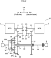
- the skeleton diagram thereof is shown in FIG. 2 .
- This drive device 10 is a differential device for a vehicle having an AYC (Active Yaw Control) function and is interposed between the left and right wheels.
- the AYC function adjusts the magnitude of the yaw moment by controlling the share ratio of the driving forces (driving torques) on the left and right driving wheels independently, and thereby stabilizes the attitude in the yaw direction of the vehicle.
- the drive device 10 of the present embodiment also has a function for transmitting the driving torque to the left and right wheels to run the vehicle and a function for passively absorbing a difference of the rotational speed between the left and right wheels generated when the vehicle is turning.
- Joint units 8 shown in FIG. 2 are connected to non-illustrated left and right wheels.
- the drive device 10 accommodates, in a casing 4, two electric motors 1, 2 that drive two left and right wheels and a planetary gear mechanism 3 (hereinafter referred to "gear mechanism 3") that amplifies the torque difference between the two motors 1, 2 and transmits torques to the left and right wheels.
- One motor 1 (hereinafter referred to as a “left motor 1”) is located on the left side of the vehicle and the other motor 2 (hereinafter referred to as a "right motor 2”) is located on the right side of the vehicle.
- the left and right motors 1, 2 are AC motors driven by electric power of a non-illustrated battery, and preferably have similar output properties. Torque of each of the left and right drive wheels is variable, and the torque difference between the left motor 1 and the right motor 2 is amplified in the gear mechanism 3 and the torques are transmitted to the left and right wheels.
- the drive device 10 of the present embodiment includes a reduction gear train that transmits the torques while reducing the rotational speeds of the motors 1, 2.
- the left motor 1 is provided with a rotor 1B which rotates integrally with a rotating shaft 1A, and a stater 1C fixed to a first casing portion 4A.
- the right motor 2 is provided with a rotor 2B which rotates integrally with a rotating shaft 2A, and a stater 2C fixed to a second casing portion 4B.
- the left motor 1 and the right motor 2 are arranges apart from and opposite to each other in such an attitude that both of the two rotating shafts 1A, 2A coincide with the vehicle width direction.
- the rotating shafts 1A, 2A are arranged on the same axial center C1 (hereinafter referred to as "first axial center C1").
- the gear mechanism 3 has a function for amplifying a torque difference at a predetermined amplification ratio, and consists of, for example, a differential mechanism or a planetary gear mechanism.
- the gear mechanism 3 includes a first sun gear 3S1 for inputting, a second sun gear 3S2 for outputting, a carrier 3C for outputting, pinion gears 3P, and a ring gear 3R for inputting. That is, the first sun gear 3S1 and the ring gear 3R are the input elements, and the second sun gear 3S2 and the carrier 3C are the output elements.
- the gear mechanism 3 are arranged on an axial center C3 (hereinafter referred to as "third axial center C3") parallel with but different from the first axial center C1 of the rotating shafts 1A, 2A, and is arranged so as to be offset to a first side in the axial direction in the casing 4.
- the gear mechanism 3 of the present embodiment is arranged so as to be offset to the left side of the vehicle. That is, "a first side in the axial direction" in the present embodiment corresponds to the left side of the vehicle, and the opposite side, that is, a second side in the axial direction corresponds to the right side of the vehicle.
- the gear mechanism 3 of the present embodiment is arranged at a position overlapping the rotor 1B and the stator 1C of the left motor 1 when viewed from a direction perpendicular to the axial direction.
- the drive device 10 includes a pair of motor shafts 11 having the same axial center C1 as the rotating shafts 1A, 2A (i.e., arranged on the first axial center C1), a pair of counter shafts 12 arranged in parallel with the motor shafts 11, and two (left and right) output shafts 13, 14 arranged in parallel with the motor shafts 11 and the counter shafts 12.
- These motor shafts 11, the counter shafts 12, and the output shafts 13, 14 are arranged in this sequence from the upstream side of the power transmission path from the respective motors 1, 2 to the left and right wheels.
- the pair of motor shafts 11 are symmetrical to each other.
- the motor shafts 11 are located between the left and right motors 1, 2, and is each fixed with a motor gear 21.
- FIG. 1 illustrates the left motor shaft 11 integrated with the rotating shaft 1A and the right motor shaft 11 integrated with the rotating shaft 2A.
- each motor shaft 11 may be separately formed from and then integrated with the corresponding one of the rotating shafts 1A, 1B.
- the pair of counter shafts 12 are arranged between the left and right motors 1, 2 on a second axial center C2 parallel with the first axial center C1 and are symmetrical to each other.
- a first counter gear 22 always meshing with a corresponding motor gear 21 and having a diameter larger than that of the motor gear 21 and a second counter gear 23 having a diameter smaller than that of the first counter gear 22 are fixed.
- the two counter gears 22, 23 are preferably arranged close to each other, and the second counter gear 23 having a smaller diameter is arranged closer to the corresponding one of the motors 1, 2 than the first counter gear 22 having a larger diameter.
- the motor gear 21 and the first counter gear 22 collectively constitute the first stage of the reduction gear train. It is sufficient that the counter shaft 12 and the two counter gears 22, 23 rotate integrally, and may be integrated with one another or may be separated from one another but fixed to one another.
- the two output shafts 13, 14 are arranged on the same axial center C3 and are asymmetrically to each other.
- first output shaft 13 the output shaft 13 on the first side (left side) to which the gear mechanism 3 is offset
- second output shaft 14 the output shaft 14 on the second side (right side)
- the first output shaft 13 is located on the first side of the gear mechanism 3, and the carrier 3C is fixed to the end portion on the other side (right end portion) of the first output shaft 13.
- the first output shaft 13 is rotatably supported with respect to the first casing portion 4A of the casing 4 by a roller bearing 34 (e.g., ball bearings).
- roller bearing 34 e.g., ball bearings
- the second output shaft 14 is longer than the first output shaft 13 and is located on the second side of the gear mechanism 3, and the second sun gear 3S2 is fixed to an end portion (left end portion) on the first side of the second output shaft 14.
- the second output shaft 14 is rotatably supported by roller bearings 35, 36 at two positions on the axial direction, as to be described below.
- the dimension in the axial direction of the second output shaft 14 is determined on the basis of the arrangement of the gear mechanism 3, but is at least larger than the half of the dimension in the vehicle width direction around the third axial center C3 of the drive device 10. Therefore, as shown in FIG. 1 , the second output shaft 14 may be formed by being spline-coupled with the middle shaft 15 arranged on the same axial center C3. This configuration enhances the assemblability of the second output shaft 14.
- the gear mechanism 3 of the present embodiment In the gear mechanism 3, the torque of the left motor 1 is input into the ring gear 3R, the torque of the right motor 2 is input into the first sun gear 3S1, the torque is output from the carrier 3C to the left wheel, and the torque is output from the second sun gear 3S2 to the right wheel.
- the ring gear 3R is integrally provided with a first driven gear 24 which always meshes with the second counter gear 23 on the first side (left side).
- the ring gear 3R and the first driven gear 24 are formed on the bottomed cylindrical portion 16.
- the bottomed cylindrical portion 16 is arranged on the third axial center C3 in such a posture that the opening thereof is directed to the first side (left side), a tooth unit serving as the ring gear 3R is formed at a portion close to the opening on the inner circumference surface of the bottomed cylindrical portion 16, and a tooth unit serving as the first driven gear 24 is formed at a portion close to the bottom on the outer circumference surface of the bottomed cylindrical portion 16.
- a small-diameter cylindrical portion 17 is integrally provided through the bottom face of the bottomed cylindrical portion 16, and the cylindrical portion 17 is rotatably supported with respect to a center casing portion 4C of the casing 4.
- the first sun gear 3S1 On the inside in the radial direction of the ring gear 3R, the first sun gear 3S1 that rotates around the third axis center C3 and a large-diameter portion 3Pa of the pinion gear 3P meshing with both the ring gear 3R and the first sun gear3S1 are arranged.
- the first sun gear 3S1 is arranged so as to extend in the axial direction toward the second side and is also integrated with a hollow shaft portion 18 inside of which the second output shaft 14 is inserted.
- the first sun gear 3S1 is disposed, and with the end portion on the second side of the hollow shaft portion 18, a hub of a second driven gear 25 that always meshes with the second counter gear 23 arranged on the second side (right side) is spline-coupled. That is, the first sun gear 3S1 and the second driven gear 25 rotate integrally.
- the inner circumference surface of the hollow shaft portion 18 and the outer circumference surface of the second output shaft 14 are out of contact with each other, and a gap is formed between the circumference surfaces.
- the outer circumference surface of the hollow shaft portion 18 and the inner circumference surface of the cylindrical portion 17 are out of contact with each other, and a gap is formed between the circumference surfaces. Oil can enter these gaps.
- the second counter gear 23 and the first driven gear 24 on the first side and the second counter gear 23 and the second driven gear 25 on the second side collectively constitute the second stage of the reduction gear train.
- the above gears 21 to 25 are positioned on power transmission paths from the right and left motors 1, 2 to the left and right wheels.
- the pinion gear 3P includes the above large-diameter portion 3Pa and a small-diameter portion 3Pb arranged on the first side of the large-diameter portion 3Pa, and is rotatably supported with respect to the carrier 3C.
- the second sun gear 3S2 is arranged close to and on the first side (left side) of the first sun gear 3S1 and always meshes with the small-diameter portion 3Pb of the pinion gear 3P.
- the carrier 3C includes a disc portion concentric with the third axial center C3 and arranged on the first side of the second sun gear 3S2.
- the first output shaft 13 is fixed to the disc portion of the carrier 3C.
- the first output shaft 13 and the disc portion of the carrier 3C may be integrated.
- the casing 4 consists of three components. Specifically, the casing 4 is formed by combining the first casing portion 4A covering the first side of the left motor 1 and the first side of the gear mechanism 3, the second casing portion 4B covering the second side of the right motor 2, and the center casing portion 4C disposed between the two casing portions 4A, 4B.
- the neighboring casing portions 4A and 4C and the neighboring casing portions 4B and 4C are fixed to each other by non-illustrated fasteners.
- the center casing portion 4C has a partition wall 4D that partitions the inside of the casing 4 into left and right spaces. On the partition wall 4D, bearings that rotatably support, for example, the motor shafts 11 and the counter shafts 12 are fixed, and a through hole through which, for example, the second output shaft 14 and the hollow shaft portion 18 are inserted is formed.
- the configuration of the casing 4 is exemplary, and is not limited to that illustrated in FIG. 1 .
- the casing 4 may consist of two components, or a combination of four or more components.
- the drive device 10 of the present embodiment includes two supporting members 5, 6 that are fixed to the casing 4 in the casing 4.
- Each of the supporting members 5, 6 is a component in the form of a flat plate, and is fixed to the casing 4 with a non-illustrated fastener so as to extend in a direction perpendicular to the axial direction.
- the first supporting member 5 arranged on the first side is arranged at a position overlapping the bottomed cylindrical portion 16 when viewed from a direction perpendicular to the axial direction, and is arranged on the second side from the rotor 1B and the stator 1C of the left motor 1.
- a bearing that supports one end portion of the counter shaft 12 arranged on the first side is fixed to the first supporting member 5.
- the second supporting member 6 arranged on the second side is arranged on the second side from the second driven gear 25 and on the first side from the rotor 2B and the stator 2C of the right motor 2.
- the second output shaft 14 is rotatably supported at the end portion (right end portion) on the second side with respect to the second casing portion 4B of the casing 4 by a ball bearing serving as the roller bearing 35.
- the second output shaft 14 is further rotatably supported at a position on the second side from the second driven gear 25 with respect to the second supporting member 6 fixed to the casing 4 by a needle bearing serving as the roller bearing 36.
- the roller bearing 36 is fixed to a hole portion penetrating the second supporting member 6.
- the space on the first side from the second driven gear 25 is narrow because cylindrical components such as the hub of the second driven gear 25, the hollow shaft portion 18, and the cylindrical portion 17 are arranged, but a relatively wide space is reserved on the second side from the second driven gear 25 because the gear mechanism 3 is arranged so as to be offset.
- the roller bearing 36 which is arranged at a position facing this wide space, is supplied with sufficient oil, so that the lubricating performance is enhanced.
- the second output shaft 14 of the present embodiment is further rotatably supported at the end portion on the first side.
- the drive device 10 further includes a recess portion 3Ca formed by recessing a surface of the disc portion of the carrier 3C which surface is facing the second sun gear 3S2, a bush 39 fixed inside the recess portion 3Ca, and a protrusion portion 14a protruding from an end surface on the first side of the second output shaft 14 and rotatably supported with respect to the bush 39.
- the recess portion 3Ca is a portion that forms a cylindrical space centered on third axial center C3, and the bush 39 is fixed to the inner circumference surface of the recess portion 3Ca.
- An example of the bush 39 is an oilless bush.
- the bush 39 supports the protrusion portion 14a formed on the first side of the second output shaft 14, so that the inclination of the second output shaft 14 is suppressed.
- the aligning effect of the planetary is a characteristic of a planetary gear mechanism in which reaction force is generated at each of the meshing points, the sun gear and the ring gear automatically perform center alignment by the reaction force, and automatically perform the centering until the force is balanced. If this aligning effect does not work properly, partial contact and/or uneven load on the pinion gears 3P are generated to increase inputs into the second sun gear 3S2 and/or the pinion gears 3P, resulting in lowering of the strength.
- the inclination of the second output shaft 14 can be avoided by the structure that provides the protrusion portion 14a on the tip of the second output shaft 14, provides the recess portion 3Ca on the carrier 3C, and rotatably supporting the protrusion portion 14a by the bush 39 in the recess portion 3Ca.
- the planetary since appropriate backlash can be ensured by meshing of the second sun gear 3S2 fixed to the end portion of the second output shaft 14 with the pinion gears 3P, the planetary can smoothly undergo alignment and can avoid partial contact and/or uneven meshing, so that an expected strength can be ensured.
- the roller bearing 36 can be arranged even in a narrow space without requiring an additional member.
- the fixing point of the roller bearing 36 may be a different component (e.g., a component constitutes the casing 4) from the second supporting member 6 or may be another supporting member.
- the type of the roller bearing 36 is not limited to a needle bearing, and the type of the roller bearing 35 is not limited to a ball bearing.
- the second output shaft 14 is not spline-coupled with the middle shaft 15, but may alternatively be formed of a single shaft member.
- the supporting structure formed by the protrusion portion 14a at the tip of the second output shaft 14 and the recess portion 3Ca of the carrier 3C are not essential and can be omitted.
- the pair of motor shafts 11 and the pair of counter shafts 12 are configured to be symmetrical, but do not necessarily have to be symmetrical.
- the gear mechanism 3 is arranged so as to be offset to the left side of the vehicle, but the gear mechanism 3 may be arranged so as to be offset to the right side of the vehicle.
- the output shaft on the second side vehicle left side
Landscapes
- Engineering & Computer Science (AREA)
- Mechanical Engineering (AREA)
- General Engineering & Computer Science (AREA)
- Chemical & Material Sciences (AREA)
- Combustion & Propulsion (AREA)
- Transportation (AREA)
- Retarders (AREA)
- Motor Power Transmission Devices (AREA)
- Gear Transmission (AREA)
- General Details Of Gearings (AREA)
Abstract
Description
- The present invention relates to a left-right wheel drive device that accommodates, in a casing, two electric motors that drive a vehicle and a planetary gear mechanism that amplifies a torque difference between the two electric motors and transmits torques to left and right wheels.
- Conventionally, a vehicle has been known which is provided with a drive device including a planetary gear mechanism that, when driving torques from two independent electric motors (hereinafter also referred to as "motors") are transmitted to left and right driving wheels, amplifies a difference (torque difference) between the two driving torques and transmits the amplified torques. The presence of such a planetary gear mechanism brings an advantage that can provide a large torque difference to the left and right wheels but also a disadvantage that increases the size of the overall drive device. As a solution to the above, a technique has been proposed which suppresses an increase of the size in the radial direction of the drive device by arranging the planetary gear mechanism such that the arrangement region in the axis direction of the planetary gear mechanism overlaps that of one of the two motors (see, for example, Patent Document 1).
- [Patent Document 1]
WO2021/039966 - Offsetting the planetary gear mechanism on one side in the axis direction in a casing of the drive device as the
above Patent Document 1 makes one of the left and right output shafts connected to an output element of the planetary gear mechanism which one is located on the other side in the axis direction longer than the other output shaft located on the one side. For example, FIG. 6 ofPatent Document 1 discloses a configuration in which a left end portion of a long second output member (output shaft) on the left side in the drawing is supported by a ball bearing, but does not disclose a supporting structure on one end side of the second output member. - The space around the one end side of the second output member is narrow because a second coupling member and a second coupling shaft are arranged. For the above, it is conceivable that the one end side of the second output member is rotatably supported by a slide baring (metal), which can be arranged in a narrow space. However, if the support structures on both end sides of the second output member are made different from each other, a friction difference occurs due to a difference in the supporting structure. Such a friction difference generates a difference in the transfer ratio between the left and right output shafts, which leads to a difference in the left and right turning properties.
- With the foregoing problems in view, one of the objects of the present invention is to ensure the stability in running straight and the equality in turning left and right without generating a friction difference between two supporting portions on a long output shaft in a left-right wheel drive device that accommodates, in a casing, two electric motors and a planetary gear mechanism. In addition to the above object, an advantageous effect that is derived from each configuration shown in the following detailed modes to carry out the present invention and which is not obtained by the conventional technique can be regarded as another object of the present disclosure.
- The disclosed left-right wheel drive device can be implemented as an embodiment or application example disclosed below, and solves at least a part of the above problem.
- The disclosed left-right wheel drive device is one that accommodates, in a casing, two electric motors that drive a vehicle and a planetary gear mechanism that amplifies a torque difference between the two electric motors and transmits torques to left and right wheels of the vehicle. The two electric motors are spaced apart from each other, and are arranged such that the rotating shafts thereof are on a same axial center. The planetary gear mechanism includes a first sun gear for inputting, a second sun gear for outputting, a carrier for outputting, pinion gears, and a ring gear for inputting, is arranged on an axial center in parallel with and different from the rotating shafts, and is arranged so as to be offset on a first side in an axial direction in the casing.
- The left-right wheel drive device includes: a pair of motor shafts having a same axial center as the rotating shafts of the two electric motors, being positioned between the two electric motors, and being fixed each with one of motor gears; a pair of counter shafts being arranged in parallel with the pair of motor shafts and being fixed each with one of first counter gears and one of second counter gears, the first counter gears each meshing with one of the motor gears, the second counter gears being smaller in diameter than the first counter gears; a first output shaft being arranged in parallel with the pair of motor shafts and on the first side from the planetary gear mechanism, and being fixed with the carrier at an end portion on a second side in the axial direction of the first output shaft; and a second output shaft being arranged on a same axial center as the first output shaft, being longer than the first output shaft, being fixed with the second sun gear at an end portion of the first side of the second output shaft. The second output shaft is rotatably supported by roller bearings at the end portion on the second side and a position on the second side from a driven gear meshing with the second counter gear arranged on the second side.
- The disclosed left-right wheel drive device generates no friction difference between two supporting portions on a long output shaft, and therefore generates no difference in the transfer ratio between the first output shaft and the second output shaft. Consequently, it is possible to ensure the stability in running straight and the equality in turning left and right.
-
- [
FIG. 1] FIG. 1 is a cross sectional view showing a left-right wheel drive device according to an embodiment. - [
FIG. 2] FIG. 2 is a skeleton diagram of the left-right wheel drive device ofFIG. 1 . - [
FIG. 3] FIG. 3 is an enlarged view of a principle part of the left-right wheel drive device ofFIG. 1 . - [
FIG. 4] FIG. 4 is an enlarged view of a principle part of the left-right wheel drive device ofFIG. 1 . - Hereinafter, description will be made in relation to an embodiment applied with the disclosed left-right wheel drive device. The following embodiment is merely exemplary, and there is no intention to eliminate the application of various modifications and techniques not explicitly described in the following embodiment. The configurations of the following embodiment can be variously modified without departing from the scope thereof. Furthermore, the configurations can be selected or omitted according to the requirement or appropriately combined. In the following description, a direction in which a vehicle moves forward is referred to as front (vehicle front), the left and right directions are defined on the basis of the front, and the left-right direction of the vehicle is also referred to as a vehicle width direction.
- The left-right wheel drive device (hereinafter referred to as "
drive device 10") of the present embodiment is shown inFIG. 1 , and the skeleton diagram thereof is shown inFIG. 2 . Thisdrive device 10 is a differential device for a vehicle having an AYC (Active Yaw Control) function and is interposed between the left and right wheels. The AYC function adjusts the magnitude of the yaw moment by controlling the share ratio of the driving forces (driving torques) on the left and right driving wheels independently, and thereby stabilizes the attitude in the yaw direction of the vehicle. Besides the AYC function, thedrive device 10 of the present embodiment also has a function for transmitting the driving torque to the left and right wheels to run the vehicle and a function for passively absorbing a difference of the rotational speed between the left and right wheels generated when the vehicle is turning.Joint units 8 shown inFIG. 2 are connected to non-illustrated left and right wheels. - The
drive device 10 accommodates, in acasing 4, twoelectric motors gear mechanism 3") that amplifies the torque difference between the twomotors left motor 1") is located on the left side of the vehicle and the other motor 2 (hereinafter referred to as a "right motor 2") is located on the right side of the vehicle. - The left and
right motors left motor 1 and theright motor 2 is amplified in thegear mechanism 3 and the torques are transmitted to the left and right wheels. Thedrive device 10 of the present embodiment includes a reduction gear train that transmits the torques while reducing the rotational speeds of themotors - The
left motor 1 is provided with arotor 1B which rotates integrally with a rotatingshaft 1A, and astater 1C fixed to afirst casing portion 4A. Similarly, theright motor 2 is provided with arotor 2B which rotates integrally with a rotatingshaft 2A, and astater 2C fixed to asecond casing portion 4B. Theleft motor 1 and theright motor 2 are arranges apart from and opposite to each other in such an attitude that both of the two rotatingshafts shafts - The
gear mechanism 3 has a function for amplifying a torque difference at a predetermined amplification ratio, and consists of, for example, a differential mechanism or a planetary gear mechanism. As shown inFIGs. 1 and2 , thegear mechanism 3 includes a first sun gear 3S1 for inputting, a second sun gear 3S2 for outputting, acarrier 3C for outputting,pinion gears 3P, and aring gear 3R for inputting. That is, the first sun gear 3S1 and thering gear 3R are the input elements, and the second sun gear 3S2 and thecarrier 3C are the output elements. - The
gear mechanism 3 are arranged on an axial center C3 (hereinafter referred to as "third axial center C3") parallel with but different from the first axial center C1 of the rotatingshafts casing 4. Thegear mechanism 3 of the present embodiment is arranged so as to be offset to the left side of the vehicle. That is, "a first side in the axial direction" in the present embodiment corresponds to the left side of the vehicle, and the opposite side, that is, a second side in the axial direction corresponds to the right side of the vehicle. Thegear mechanism 3 of the present embodiment is arranged at a position overlapping therotor 1B and thestator 1C of theleft motor 1 when viewed from a direction perpendicular to the axial direction. - The
drive device 10 includes a pair ofmotor shafts 11 having the same axial center C1 as therotating shafts counter shafts 12 arranged in parallel with themotor shafts 11, and two (left and right)output shafts motor shafts 11 and thecounter shafts 12. Thesemotor shafts 11, thecounter shafts 12, and theoutput shafts respective motors - In the present embodiment, the pair of
motor shafts 11 are symmetrical to each other. Themotor shafts 11 are located between the left andright motors motor gear 21.FIG. 1 illustrates theleft motor shaft 11 integrated with therotating shaft 1A and theright motor shaft 11 integrated with therotating shaft 2A. Alternatively, eachmotor shaft 11 may be separately formed from and then integrated with the corresponding one of therotating shafts - In the present embodiment, the pair of
counter shafts 12 are arranged between the left andright motors counter shaft 12, afirst counter gear 22 always meshing with acorresponding motor gear 21 and having a diameter larger than that of themotor gear 21 and asecond counter gear 23 having a diameter smaller than that of thefirst counter gear 22 are fixed. The two counter gears 22, 23 are preferably arranged close to each other, and thesecond counter gear 23 having a smaller diameter is arranged closer to the corresponding one of themotors first counter gear 22 having a larger diameter. Themotor gear 21 and thefirst counter gear 22 collectively constitute the first stage of the reduction gear train. It is sufficient that thecounter shaft 12 and the two counter gears 22, 23 rotate integrally, and may be integrated with one another or may be separated from one another but fixed to one another. - The two
output shafts output shaft 13 on the first side (left side) to which thegear mechanism 3 is offset is referred to as "first output shaft 13", and theoutput shaft 14 on the second side (right side) is referred to as "second output shaft 14". Thefirst output shaft 13 is located on the first side of thegear mechanism 3, and thecarrier 3C is fixed to the end portion on the other side (right end portion) of thefirst output shaft 13. Thefirst output shaft 13 is rotatably supported with respect to thefirst casing portion 4A of thecasing 4 by a roller bearing 34 (e.g., ball bearings). - The
second output shaft 14 is longer than thefirst output shaft 13 and is located on the second side of thegear mechanism 3, and the second sun gear 3S2 is fixed to an end portion (left end portion) on the first side of thesecond output shaft 14. Thesecond output shaft 14 is rotatably supported byroller bearings second output shaft 14 is determined on the basis of the arrangement of thegear mechanism 3, but is at least larger than the half of the dimension in the vehicle width direction around the third axial center C3 of thedrive device 10. Therefore, as shown inFIG. 1 , thesecond output shaft 14 may be formed by being spline-coupled with themiddle shaft 15 arranged on the same axial center C3. This configuration enhances the assemblability of thesecond output shaft 14. - Description will now be made in relation to the
gear mechanism 3 of the present embodiment. In thegear mechanism 3, the torque of theleft motor 1 is input into thering gear 3R, the torque of theright motor 2 is input into the first sun gear 3S1, the torque is output from thecarrier 3C to the left wheel, and the torque is output from the second sun gear 3S2 to the right wheel. Thering gear 3R is integrally provided with a first drivengear 24 which always meshes with thesecond counter gear 23 on the first side (left side). In thegear mechanism 3 of the present embodiment, thering gear 3R and the first drivengear 24 are formed on the bottomedcylindrical portion 16. - Specifically, the bottomed
cylindrical portion 16 is arranged on the third axial center C3 in such a posture that the opening thereof is directed to the first side (left side), a tooth unit serving as thering gear 3R is formed at a portion close to the opening on the inner circumference surface of the bottomedcylindrical portion 16, and a tooth unit serving as the first drivengear 24 is formed at a portion close to the bottom on the outer circumference surface of the bottomedcylindrical portion 16. A small-diametercylindrical portion 17 is integrally provided through the bottom face of the bottomedcylindrical portion 16, and thecylindrical portion 17 is rotatably supported with respect to acenter casing portion 4C of thecasing 4. - On the inside in the radial direction of the
ring gear 3R, the first sun gear 3S1 that rotates around the third axis center C3 and a large-diameter portion 3Pa of thepinion gear 3P meshing with both thering gear 3R and the first sun gear3S1 are arranged. The first sun gear 3S1 is arranged so as to extend in the axial direction toward the second side and is also integrated with ahollow shaft portion 18 inside of which thesecond output shaft 14 is inserted. At the end portion on the first side of thehollow shaft portion 18, the first sun gear 3S1 is disposed, and with the end portion on the second side of thehollow shaft portion 18, a hub of a second drivengear 25 that always meshes with thesecond counter gear 23 arranged on the second side (right side) is spline-coupled. That is, the first sun gear 3S1 and the second drivengear 25 rotate integrally. - The inner circumference surface of the
hollow shaft portion 18 and the outer circumference surface of thesecond output shaft 14 are out of contact with each other, and a gap is formed between the circumference surfaces. Similarly, the outer circumference surface of thehollow shaft portion 18 and the inner circumference surface of thecylindrical portion 17 are out of contact with each other, and a gap is formed between the circumference surfaces. Oil can enter these gaps. Thesecond counter gear 23 and the first drivengear 24 on the first side and thesecond counter gear 23 and the second drivengear 25 on the second side collectively constitute the second stage of the reduction gear train. The above gears 21 to 25 are positioned on power transmission paths from the right and leftmotors - The
pinion gear 3P includes the above large-diameter portion 3Pa and a small-diameter portion 3Pb arranged on the first side of the large-diameter portion 3Pa, and is rotatably supported with respect to thecarrier 3C. The second sun gear 3S2 is arranged close to and on the first side (left side) of the first sun gear 3S1 and always meshes with the small-diameter portion 3Pb of thepinion gear 3P. Thecarrier 3C includes a disc portion concentric with the third axial center C3 and arranged on the first side of the second sun gear 3S2. Thefirst output shaft 13 is fixed to the disc portion of thecarrier 3C. Thefirst output shaft 13 and the disc portion of thecarrier 3C may be integrated. - Next, description will now be made in relation to the
casing 4. As shown inFIG. 1 , in thedrive device 10 of the present embodiment, thecasing 4 consists of three components. Specifically, thecasing 4 is formed by combining thefirst casing portion 4A covering the first side of theleft motor 1 and the first side of thegear mechanism 3, thesecond casing portion 4B covering the second side of theright motor 2, and thecenter casing portion 4C disposed between the twocasing portions casing portions casing portions - The
center casing portion 4C has apartition wall 4D that partitions the inside of thecasing 4 into left and right spaces. On thepartition wall 4D, bearings that rotatably support, for example, themotor shafts 11 and thecounter shafts 12 are fixed, and a through hole through which, for example, thesecond output shaft 14 and thehollow shaft portion 18 are inserted is formed. The configuration of thecasing 4 is exemplary, and is not limited to that illustrated inFIG. 1 . Alternatively, thecasing 4 may consist of two components, or a combination of four or more components. - The
drive device 10 of the present embodiment includes two supportingmembers casing 4 in thecasing 4. Each of the supportingmembers casing 4 with a non-illustrated fastener so as to extend in a direction perpendicular to the axial direction. The first supportingmember 5 arranged on the first side is arranged at a position overlapping the bottomedcylindrical portion 16 when viewed from a direction perpendicular to the axial direction, and is arranged on the second side from therotor 1B and thestator 1C of theleft motor 1. A bearing that supports one end portion of thecounter shaft 12 arranged on the first side is fixed to the first supportingmember 5. - The second supporting
member 6 arranged on the second side is arranged on the second side from the second drivengear 25 and on the first side from therotor 2B and thestator 2C of theright motor 2. To the second supportingmember 6, at least abearing 33 that supports the other end portion of thecounter shaft 12 arranged on the second side and a bearing that supports the hub of the second drivengear 25 are fixed. - Next, description will now be made in relation to a supporting structure of the
second output shaft 14. As shown inFIGs. 1 to 3 , thesecond output shaft 14 is rotatably supported at the end portion (right end portion) on the second side with respect to thesecond casing portion 4B of thecasing 4 by a ball bearing serving as theroller bearing 35. Thesecond output shaft 14 is further rotatably supported at a position on the second side from the second drivengear 25 with respect to the second supportingmember 6 fixed to thecasing 4 by a needle bearing serving as theroller bearing 36. Theroller bearing 36 is fixed to a hole portion penetrating the second supportingmember 6. - The space on the first side from the second driven
gear 25 is narrow because cylindrical components such as the hub of the second drivengear 25, thehollow shaft portion 18, and thecylindrical portion 17 are arranged, but a relatively wide space is reserved on the second side from the second drivengear 25 because thegear mechanism 3 is arranged so as to be offset. With this structure, theroller bearing 36, which is arranged at a position facing this wide space, is supplied with sufficient oil, so that the lubricating performance is enhanced. - In addition to the two
roller bearings second output shaft 14 of the present embodiment is further rotatably supported at the end portion on the first side. Specifically, as shown inFIGs. 1 and4 , thedrive device 10 further includes a recess portion 3Ca formed by recessing a surface of the disc portion of thecarrier 3C which surface is facing the second sun gear 3S2, abush 39 fixed inside the recess portion 3Ca, and aprotrusion portion 14a protruding from an end surface on the first side of thesecond output shaft 14 and rotatably supported with respect to thebush 39. The recess portion 3Ca is a portion that forms a cylindrical space centered on third axial center C3, and thebush 39 is fixed to the inner circumference surface of the recess portion 3Ca. An example of thebush 39 is an oilless bush. Thebush 39 supports theprotrusion portion 14a formed on the first side of thesecond output shaft 14, so that the inclination of thesecond output shaft 14 is suppressed. -
- (1) In the above-described
drive device 10, thesecond output shaft 14, which has been made longer by arranging thegear mechanism 3 to be offset to the first side in the axial direction, is rotatably supported by the tworoller bearings right output shafts roller bearing 36 faces a relatively wide space of the casing and the second supporting member because supporting thesecond output shaft 14 at the position on the second side from the second drivengear 25 in thesecond output shaft 14, so that sufficient oil can be supplied and the lubricating performance can be enhanced. - (2) According to the
drive device 10 described above, since the inner circumference surface of thehollow shaft portion 18, which connects the first sun gear 3S1 to the second drivengear 25, and the outer circumference surface of thesecond output shaft 14 are out of contact with each other, it is possible to prevent seizure due to rotation. In addition, in a configuration that supports the second output shaft with the metal, it is difficult to supply the metal supporting portion with sufficient oil because the configuration has three axes. However, a configuration that supports thesecond output shaft 14 with theroller bearing 36 and reserves a gap space between thehollow shaft portion 18 and thesecond output shaft 14 eliminates the requirement for oil supply and therefore can eliminate a lubricating hole for ensuring the lubricating performance. - (3) Incidentally, if the middle portion in the axis direction of the
second output shaft 14 is configured to be supported by the roller bearing 36 (e.g., a needle bearing) as described above and themiddle shaft 15 is configured to be spline-coupled, the second sun gear 3S2 fixed to the end portion of themiddle shaft 15 inclines and the meshing of the second sun gear 3S2 with thepinion gear 3P would be in a non-backlash state. - If it is impossible to ensure appropriate backlash between meshing gears, the aligning effect of the planetary less works due to the occurrence of tooth interference, which leads to wearing of the tooth surface and degrading of the strength reduction. The aligning effect of the planetary is a characteristic of a planetary gear mechanism in which reaction force is generated at each of the meshing points, the sun gear and the ring gear automatically perform center alignment by the reaction force, and automatically perform the centering until the force is balanced. If this aligning effect does not work properly, partial contact and/or uneven load on the pinion gears 3P are generated to increase inputs into the second sun gear 3S2 and/or the pinion gears 3P, resulting in lowering of the strength.
- To solve this problem, as described above, the inclination of the
second output shaft 14 can be avoided by the structure that provides theprotrusion portion 14a on the tip of thesecond output shaft 14, provides the recess portion 3Ca on thecarrier 3C, and rotatably supporting theprotrusion portion 14a by thebush 39 in the recess portion 3Ca. As a result, since appropriate backlash can be ensured by meshing of the second sun gear 3S2 fixed to the end portion of thesecond output shaft 14 with the pinion gears 3P, the planetary can smoothly undergo alignment and can avoid partial contact and/or uneven meshing, so that an expected strength can be ensured. - (4) In addition, as shown in
FIG. 1 , if thesecond output shaft 14 is configured by being spline-coupled with themiddle shaft 15, which means that the longsecond output shaft 14 is of an assembling type, the assemblability can be improved. - (5) Further, since, in the
drive device 10 described above, the needle bearing serving as theroller bearing 36 is fixed to the second supportingmember 6 to which thebearing 33 of thecounter shaft 12 arranged on the second side is fixed, theroller bearing 36 can be arranged even in a narrow space without requiring an additional member. - The structure of the
drive device 10 described above is an example, but is not limited to one described above. Alternatively, the fixing point of theroller bearing 36 may be a different component (e.g., a component constitutes the casing 4) from the second supportingmember 6 or may be another supporting member. The type of theroller bearing 36 is not limited to a needle bearing, and the type of theroller bearing 35 is not limited to a ball bearing. - The
second output shaft 14 is not spline-coupled with themiddle shaft 15, but may alternatively be formed of a single shaft member. In addition, the supporting structure formed by theprotrusion portion 14a at the tip of thesecond output shaft 14 and the recess portion 3Ca of thecarrier 3C are not essential and can be omitted. - In the
drive device 10 described above, the pair ofmotor shafts 11 and the pair ofcounter shafts 12 are configured to be symmetrical, but do not necessarily have to be symmetrical. - In the
drive device 10 described above, thegear mechanism 3 is arranged so as to be offset to the left side of the vehicle, but thegear mechanism 3 may be arranged so as to be offset to the right side of the vehicle. In this case, since the output shaft on the second side (vehicle left side) comes to be long, it is sufficient that the above configuration is inverted with respect to the left-right direction and then applied to the alternative. -
- 1: left motor (electric motor)
- 1A: rotating shaft
- 2: right motor (electric motor)
- 2A: rotating shaft
- 3: gear mechanism (planetary gear mechanism)
- 3C: carrier
- 3Ca: recess portion
- 3P: pinion gear
- 3R: ring gear
- 3S1: first sun gear
- 3S2: second sun gear
- 4: casing
- 6: second supporting member (supporting member)
- 10: drive device (left-right wheel drive device)
- 11: motor shaft
- 12: counter shaft
- 13: first output shaft
- 14: second output shaft
- 14a: protrusion portion
- 15: middle shaft
- 18: hollow shaft portion
- 21: motor gear
- 22: first counter gear
- 23: second counter gear
- 24: first driven gear
- 25: second driven gear (driven gear)
- 35: roller bearing
- 36: roller bearing (needle bearing)
- 39: bush
Claims (5)
- A left-right wheel drive device that accommodates, in a casing, two electric motors that drive a vehicle and a planetary gear mechanism that amplifies a torque difference between the two electric motors and transmits torques to left and right wheels of the vehicle, whereinthe two electric motors are spaced apart from each other and are arranged such that rotating shafts thereof are on a same axial center;the planetary gear mechanism comprises a first sun gear for inputting, a second sun gear for outputting, a carrier for outputting, pinion gears, and a ring gear for inputting, is arranged on an axial center in parallel with and different from the rotating shafts, and, is arranged so as to be offset on a first side in an axial direction in the casing;the left-right wheel drive device comprisesa pair of motor shafts having a same axial center as the rotating shafts of the two electric motors, being positioned between the two electric motors, and being fixed each with one of motor gears,a pair of counter shafts being arranged in parallel with the pair of motor shafts and being fixed each with one of first counter gears and one of second counter gears, the first counter gears each meshing with one of the motor gears, the second counter gears being smaller in diameter than the first counter gears,a first output shaft being arranged in parallel with the pair of motor shafts and on the first side from the planetary gear mechanism, and being fixed with the carrier at an end portion on a second side in the axial direction of the first output shaft, anda second output shaft being arranged on a same axial center as the first output shaft, being longer than the first output shaft, being fixed with the second sun gear at an end portion on the first side of the second output shaft; andthe second output shaft is rotatably supported by roller bearings at the end portion on the second side and a position on the second side from a driven gear meshing with the second counter gear arranged on the second side.
- The left-right wheel drive device according to claim 1, whereinthe driven gear and the first sun gear are coupled to each other by a hollow shaft portion, the second output shaft being inserted through an inside of the hollow shaft portion, andan inner circumference surface of the hollow shaft portion is out of contact with an outer circumference of the second output shaft.
- The left-right wheel drive device according to claim 1 or 2, further comprising:a recess portion formed by recessing a face of the carrier, the face being opposite to the second sun gear;a bush fixed to an inside of the recess portion; anda protrusion portion protruding from an edge face on the first side of the second output shaft and being rotatably supported by the bush.
- The left-right wheel drive device according to one of claims 1-3, wherein
the second output shaft is formed by being spline-coupled with a middle shaft arranged on a same axial center. - The left-right wheel drive device according to one of claims 1-4, further comprisinga supporting member being fixed to the casing, and being fixed with a bearing rotatably supporting an end portion on the second side of one of the pair of counter shafts arranged on the second side, whereinthe roller bearing at the position of the second output shaft is a needle bearing fixed to a hole portion penetrating through the supporting member.
Applications Claiming Priority (2)
| Application Number | Priority Date | Filing Date | Title |
|---|---|---|---|
| JP2022011499 | 2022-01-28 | ||
| PCT/JP2022/045141 WO2023145267A1 (en) | 2022-01-28 | 2022-12-07 | Left-right wheel drive device |
Publications (2)
| Publication Number | Publication Date |
|---|---|
| EP4471293A1 true EP4471293A1 (en) | 2024-12-04 |
| EP4471293A4 EP4471293A4 (en) | 2025-10-22 |
Family
ID=87471595
Family Applications (1)
| Application Number | Title | Priority Date | Filing Date |
|---|---|---|---|
| EP22924119.5A Pending EP4471293A4 (en) | 2022-01-28 | 2022-12-07 | LEFT-RIGHT WHEEL DRIVE DEVICE |
Country Status (5)
| Country | Link |
|---|---|
| US (1) | US12403761B2 (en) |
| EP (1) | EP4471293A4 (en) |
| JP (1) | JP7529928B2 (en) |
| CN (1) | CN118575022A (en) |
| WO (1) | WO2023145267A1 (en) |
Cited By (1)
| Publication number | Priority date | Publication date | Assignee | Title |
|---|---|---|---|---|
| US12533948B2 (en) | 2023-02-22 | 2026-01-27 | Toyota Jidosha Kabushiki Kaisha | Power transmission device and drive device |
Families Citing this family (2)
| Publication number | Priority date | Publication date | Assignee | Title |
|---|---|---|---|---|
| EP4676759A1 (en) * | 2023-03-10 | 2026-01-14 | Doosan Bobcat North America, Inc. | Power system assembly for a power machine |
| US20240336121A1 (en) * | 2023-04-04 | 2024-10-10 | Toyota Motor Engineering & Manufacturing North America, Inc. | Dual Electric Motor Assembly Systems and Methods |
Family Cites Families (10)
| Publication number | Priority date | Publication date | Assignee | Title |
|---|---|---|---|---|
| JPH11243664A (en) * | 1998-02-24 | 1999-09-07 | Honda Motor Co Ltd | Electric drive system for vehicles |
| US7298108B2 (en) * | 2004-11-29 | 2007-11-20 | Smc Kabushiki Kaisha | Control system for electric actuator |
| JP2018028365A (en) * | 2016-08-19 | 2018-02-22 | Ntn株式会社 | Vehicle drive unit |
| JP2018061306A (en) * | 2016-10-03 | 2018-04-12 | Ntn株式会社 | Drive source control device |
| JP2018084315A (en) * | 2016-11-25 | 2018-05-31 | 三菱自動車工業株式会社 | Drive device |
| JP2018155310A (en) * | 2017-03-17 | 2018-10-04 | Ntn株式会社 | Four-wheel drive vehicle |
| EP3667876B1 (en) * | 2017-11-17 | 2022-11-23 | Aisin Corporation | Vehicle drive device |
| WO2020179202A1 (en) * | 2019-03-06 | 2020-09-10 | 三菱自動車工業株式会社 | Left-right wheel driving device |
| JP7437406B2 (en) * | 2019-08-29 | 2024-02-22 | 株式会社アイシン | Vehicle drive system |
| JP2021055772A (en) * | 2019-09-30 | 2021-04-08 | アイシン・エィ・ダブリュ株式会社 | Vehicle driving device |
-
2022
- 2022-12-07 EP EP22924119.5A patent/EP4471293A4/en active Pending
- 2022-12-07 CN CN202280089594.0A patent/CN118575022A/en active Pending
- 2022-12-07 WO PCT/JP2022/045141 patent/WO2023145267A1/en not_active Ceased
- 2022-12-07 JP JP2023576673A patent/JP7529928B2/en active Active
- 2022-12-07 US US18/727,553 patent/US12403761B2/en active Active
Cited By (1)
| Publication number | Priority date | Publication date | Assignee | Title |
|---|---|---|---|---|
| US12533948B2 (en) | 2023-02-22 | 2026-01-27 | Toyota Jidosha Kabushiki Kaisha | Power transmission device and drive device |
Also Published As
| Publication number | Publication date |
|---|---|
| US20250074186A1 (en) | 2025-03-06 |
| EP4471293A4 (en) | 2025-10-22 |
| WO2023145267A1 (en) | 2023-08-03 |
| JPWO2023145267A1 (en) | 2023-08-03 |
| CN118575022A (en) | 2024-08-30 |
| US12403761B2 (en) | 2025-09-02 |
| JP7529928B2 (en) | 2024-08-06 |
Similar Documents
| Publication | Publication Date | Title |
|---|---|---|
| US12403761B2 (en) | Left-right wheel drive device | |
| EP3936371B1 (en) | Left-right wheel driving device | |
| US11207984B2 (en) | Drive source control device | |
| US11110805B2 (en) | Control device for left and right wheel drive device | |
| CN103547836B (en) | Speed reduction differential device for electric vehicle | |
| EP3667876B1 (en) | Vehicle drive device | |
| EP1998080B1 (en) | Final reduction gear device | |
| US8545356B2 (en) | Speed change gear device | |
| JP2003143805A (en) | Rotating electric machine | |
| JP2015524644A (en) | Electric axle support concept | |
| CN103459891A (en) | Friction roller type deceleration device and drive device for electric automobile | |
| WO2009113257A1 (en) | Carrier assembly for supporting pinion gear | |
| EP3922880A1 (en) | Power transmission device | |
| CN108368927A (en) | Transmission device and differential gear | |
| JP4891890B2 (en) | Final reduction gear | |
| NL2029077B1 (en) | Final stage gear wheel assembly | |
| US20250033450A1 (en) | Electric vehicle | |
| US12584542B2 (en) | Transmission and drive train for a motor vehicle | |
| JPH11210773A (en) | Bearings for double-cavity toroidal type continuously variable transmission | |
| JP2006189064A (en) | Driving force transmission device | |
| WO2017131141A1 (en) | Transmission device | |
| JP2006097804A (en) | Assembly structure of vertical transaxle drive pinion shaft | |
| JP2018040424A (en) | Support structure of power transmission device for vehicle | |
| WO2017170589A1 (en) | Transmission device |
Legal Events
| Date | Code | Title | Description |
|---|---|---|---|
| STAA | Information on the status of an ep patent application or granted ep patent |
Free format text: STATUS: THE INTERNATIONAL PUBLICATION HAS BEEN MADE |
|
| PUAI | Public reference made under article 153(3) epc to a published international application that has entered the european phase |
Free format text: ORIGINAL CODE: 0009012 |
|
| STAA | Information on the status of an ep patent application or granted ep patent |
Free format text: STATUS: REQUEST FOR EXAMINATION WAS MADE |
|
| 17P | Request for examination filed |
Effective date: 20240809 |
|
| AK | Designated contracting states |
Kind code of ref document: A1 Designated state(s): AL AT BE BG CH CY CZ DE DK EE ES FI FR GB GR HR HU IE IS IT LI LT LU LV MC ME MK MT NL NO PL PT RO RS SE SI SK SM TR |
|
| DAV | Request for validation of the european patent (deleted) | ||
| DAX | Request for extension of the european patent (deleted) | ||
| A4 | Supplementary search report drawn up and despatched |
Effective date: 20250919 |
|
| RIC1 | Information provided on ipc code assigned before grant |
Ipc: F16H 57/021 20120101AFI20250915BHEP Ipc: B60K 17/12 20060101ALI20250915BHEP Ipc: F16H 1/06 20060101ALI20250915BHEP Ipc: F16H 48/11 20120101ALI20250915BHEP Ipc: F16H 57/08 20060101ALI20250915BHEP Ipc: F16H 57/00 20120101ALI20250915BHEP |