EP4471265A2 - Leistungskopplungssystem einer zwischenrotierenden anordnung für einen turbinenmotor - Google Patents
Leistungskopplungssystem einer zwischenrotierenden anordnung für einen turbinenmotor Download PDFInfo
- Publication number
- EP4471265A2 EP4471265A2 EP24179669.7A EP24179669A EP4471265A2 EP 4471265 A2 EP4471265 A2 EP 4471265A2 EP 24179669 A EP24179669 A EP 24179669A EP 4471265 A2 EP4471265 A2 EP 4471265A2
- Authority
- EP
- European Patent Office
- Prior art keywords
- electric machine
- differential
- assembly
- geartrain
- coupled
- Prior art date
- Legal status (The legal status is an assumption and is not a legal conclusion. Google has not performed a legal analysis and makes no representation as to the accuracy of the status listed.)
- Pending
Links
Images


Classifications
-
- F—MECHANICAL ENGINEERING; LIGHTING; HEATING; WEAPONS; BLASTING
- F02—COMBUSTION ENGINES; HOT-GAS OR COMBUSTION-PRODUCT ENGINE PLANTS
- F02C—GAS-TURBINE PLANTS; AIR INTAKES FOR JET-PROPULSION PLANTS; CONTROLLING FUEL SUPPLY IN AIR-BREATHING JET-PROPULSION PLANTS
- F02C7/00—Features, components parts, details or accessories, not provided for in, or of interest apart form groups F02C1/00 - F02C6/00; Air intakes for jet-propulsion plants
- F02C7/32—Arrangement, mounting, or driving, of auxiliaries
-
- F—MECHANICAL ENGINEERING; LIGHTING; HEATING; WEAPONS; BLASTING
- F02—COMBUSTION ENGINES; HOT-GAS OR COMBUSTION-PRODUCT ENGINE PLANTS
- F02C—GAS-TURBINE PLANTS; AIR INTAKES FOR JET-PROPULSION PLANTS; CONTROLLING FUEL SUPPLY IN AIR-BREATHING JET-PROPULSION PLANTS
- F02C7/00—Features, components parts, details or accessories, not provided for in, or of interest apart form groups F02C1/00 - F02C6/00; Air intakes for jet-propulsion plants
- F02C7/36—Power transmission arrangements between the different shafts of the gas turbine plant, or between the gas-turbine plant and the power user
-
- F—MECHANICAL ENGINEERING; LIGHTING; HEATING; WEAPONS; BLASTING
- F16—ENGINEERING ELEMENTS AND UNITS; GENERAL MEASURES FOR PRODUCING AND MAINTAINING EFFECTIVE FUNCTIONING OF MACHINES OR INSTALLATIONS; THERMAL INSULATION IN GENERAL
- F16H—GEARING
- F16H3/00—Toothed gearings for conveying rotary motion with variable gear ratio or for reversing rotary motion
- F16H3/44—Toothed gearings for conveying rotary motion with variable gear ratio or for reversing rotary motion using gears having orbital motion
- F16H3/72—Toothed gearings for conveying rotary motion with variable gear ratio or for reversing rotary motion using gears having orbital motion with a secondary drive, e.g. regulating motor, in order to vary speed continuously
- F16H3/727—Toothed gearings for conveying rotary motion with variable gear ratio or for reversing rotary motion using gears having orbital motion with a secondary drive, e.g. regulating motor, in order to vary speed continuously with at least two dynamo electric machines for creating an electric power path inside the gearing, e.g. using generator and motor for a variable power torque path
-
- F—MECHANICAL ENGINEERING; LIGHTING; HEATING; WEAPONS; BLASTING
- F16—ENGINEERING ELEMENTS AND UNITS; GENERAL MEASURES FOR PRODUCING AND MAINTAINING EFFECTIVE FUNCTIONING OF MACHINES OR INSTALLATIONS; THERMAL INSULATION IN GENERAL
- F16H—GEARING
- F16H48/00—Differential gearings
- F16H48/06—Differential gearings with gears having orbital motion
- F16H48/10—Differential gearings with gears having orbital motion with orbital spur gears
-
- F—MECHANICAL ENGINEERING; LIGHTING; HEATING; WEAPONS; BLASTING
- F05—INDEXING SCHEMES RELATING TO ENGINES OR PUMPS IN VARIOUS SUBCLASSES OF CLASSES F01-F04
- F05D—INDEXING SCHEME FOR ASPECTS RELATING TO NON-POSITIVE-DISPLACEMENT MACHINES OR ENGINES, GAS-TURBINES OR JET-PROPULSION PLANTS
- F05D2220/00—Application
- F05D2220/70—Application in combination with
- F05D2220/76—Application in combination with an electrical generator
-
- F—MECHANICAL ENGINEERING; LIGHTING; HEATING; WEAPONS; BLASTING
- F05—INDEXING SCHEMES RELATING TO ENGINES OR PUMPS IN VARIOUS SUBCLASSES OF CLASSES F01-F04
- F05D—INDEXING SCHEME FOR ASPECTS RELATING TO NON-POSITIVE-DISPLACEMENT MACHINES OR ENGINES, GAS-TURBINES OR JET-PROPULSION PLANTS
- F05D2260/00—Function
- F05D2260/40—Transmission of power
- F05D2260/403—Transmission of power through the shape of the drive components
- F05D2260/4031—Transmission of power through the shape of the drive components as in toothed gearing
- F05D2260/40311—Transmission of power through the shape of the drive components as in toothed gearing of the epicyclical, planetary or differential type
Definitions
- an assembly for an aircraft powerplant.
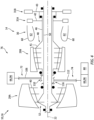
- This assembly includes a differential geartrain, a first rotating assembly, a second rotating assembly, a first actuator and a second actuator.
- the differential geartrain includes a sun gear, a ring gear, a plurality of intermediate gears and a carrier.
- the ring gear circumscribes the sun gear and is rotatable about an axis.
- Each of the intermediate gears is between and meshed with the sun gear and the ring gear.
- Each of the intermediate gears is rotatably mounted to the carrier.
- the carrier is rotatable about the axis.
- the first rotating assembly is coupled to the differential geartrain through the carrier.
- the first rotating assembly includes a first turbine rotor.
- the second rotating assembly is coupled to the differential geartrain through the ring gear.
- the second rotating assembly includes a second turbine rotor.
- the first actuator is coupled to the differential geartrain through the ring gear.
- the second actuator is coupled to the differential geartrain through the sun gear.
- this assembly includes a differential geartrain, a first rotating assembly, a second rotating assembly, a first electric machine, a second electric machine and an electricity distribution system.
- the differential geartrain includes a first rotating element, a second rotating element and a third rotating element.
- the first rotating assembly is coupled to the differential geartrain through the first rotating element.
- the first rotating assembly includes a first turbine rotor.
- the second rotating assembly is coupled to the differential geartrain through the second rotating element.
- the second rotating assembly includes a second turbine rotor.
- the first electric machine is coupled to the differential geartrain through the third rotating element.
- the second electric machine is coupled to the differential geartrain through the first rotating element.
- the electricity distribution system is electrically coupled to the first electric machine and the second electric machine.
- this assembly includes a differential geartrain, a first rotating assembly, a second rotating assembly and a compressor rotor.
- the differential geartrain includes a sun gear, a ring gear, a plurality of intermediate gears and a carrier.
- the ring gear circumscribes the sun gear and is rotatable about an axis.
- Each of the intermediate gears is between and meshed with the sun gear and the ring gear.
- Each of the intermediate gears is rotatably mounted to the carrier.
- the carrier is rotatable about the axis.
- the first rotating assembly is coupled to the differential geartrain through the carrier.
- the first rotating assembly includes a first turbine rotor.
- the second rotating assembly is coupled to the differential geartrain through the ring gear.
- the second rotating assembly includes a second turbine rotor.
- the compressor rotor is coupled to the differential geartrain through the sun gear.
- the electricity distribution system may be configured to: receive electricity from the first electric machine and direct electricity into the second electric machine during a first mode of operation; and direct electricity into the first electric machine and receive electricity from the second electric machine during a second mode of operation.
- the electricity distribution system may also be configured to receive electricity from the first electric machine and the second electric machine during a third mode of operation.
- the electricity distribution system may also be configured to direct electricity into the first electric machine and the second electric machine during a third mode of operation.
- the first rotating element may be configured as or otherwise include a carrier.
- the second rotating element may be configured as or otherwise include a ring gear.
- the third rotating element may be configured as or otherwise include a sun gear.
- the differential geartrain may also include a plurality of intermediate gears.
- the ring gear may circumscribe the sun gear and may be rotatable about an axis.
- Each of the intermediate gears may be between and meshed with the sun gear and the ring gear.
- Each of the intermediate gears may be rotatably mounted to the carrier.
- the carrier may be rotatable about the axis.
- the first actuator may be configured as or otherwise include an electric machine.
- the electric machine may be configured to: operate as an electric motor during a motor mode of operation; and/or operate as an electric generator during a generator mode of operation.
- the second actuator may be configured as or otherwise include an electric machine.
- the electric machine may be configured to: operate as an electric motor during a motor mode of operation; and/or operate as an electric generator during a generator mode of operation.
- the second actuator may be configured as or otherwise include a compressor.
- the second actuator may be configured as or otherwise include a pump.
- the differential geartrain may be configured such that the sun gear, the ring gear and the carrier rotate in a common direction about the axis.
- the first actuator may be configured as or otherwise include a first electric machine configured to generate electricity during a mode of operation.
- the second actuator may be configured as or otherwise include a second electric machine configured to drive rotation of the sun gear during the mode of operation.
- the first actuator may be configured as or otherwise include a first electric machine configured to drive rotation of the ring gear during a mode of operation.
- the second actuator may be configured as or otherwise include a second electric machine configured to generate electricity during the mode of operation.
- the first actuator may be configured as or otherwise include a first electric machine configured to generate electricity during a mode of operation.
- the second actuator may be configured as or otherwise include a second electric machine configured to generate electricity during the mode of operation.
- the first actuator may be configured as or otherwise include a first electric machine configured to drive rotation of the ring gear during a mode of operation.
- the second actuator may be configured as or otherwise include a second electric machine configured to drive rotation of the sun gear during the mode of operation.
- the assembly may also include a first tower shaft and a second tower shaft.
- the first rotating assembly may be coupled to the carrier through the first tower shaft.
- the second rotating assembly may be coupled to the ring gear through the second tower shaft.
- the assembly may also include an accessory gearbox including a gearbox geartrain.
- the first rotating assembly and the second rotating assembly may be coupled to the differential geartrain through the gearbox geartrain.
- the first actuator may be coupled to the differential geartrain through the gearbox geartrain.
- the second actuator may be coupled to the sun gear independent of the gearbox geartrain.
- the first rotating assembly may also include a compressor rotor.
- the second rotating assembly may also include a compressor rotor.
- the assembly may also include a propulsor rotor coupled to the second turbine rotor.
- the second turbine rotor may be configured to drive rotation of the propulsor rotor.
- the present disclosure may include any one or more of the individual features disclosed above and/or below alone or in any combination thereof.
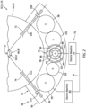
- FIG. 1 illustrates a powerplant 10 for an aircraft.
- the aircraft may be an airplane, a helicopter, a drone (e.g., an unmanned aerial vehicle (UAV)) or any other manned or unmanned aerial vehicle.
- the aircraft powerplant 10 may be configured as, or otherwise included as part of, a propulsion system for the aircraft.
- the aircraft powerplant 10 may also or alternatively be configured as, or otherwise included as part of, an electric power system for the aircraft.
- the aircraft powerplant 10 may be generally described below as the aircraft propulsion system.
- the aircraft powerplant 10 of FIG. 1 includes a mechanical load 12 and a core 14 of a gas turbine engine 16.
- the mechanical load 12 may be configured as or otherwise include a rotor 18 mechanically driven by the engine core 14.
- This driven rotor 18 may be a bladed propulsor rotor where the aircraft powerplant 10 is, or is part of, the aircraft propulsion system.
- the propulsor rotor for example, may be an open (e.g., un-ducted) propulsor rotor or a ducted propulsor rotor.
- Examples of the open propulsor rotor include, but are not limited to, a propfan rotor for a propfan propulsion system, a pusher fan rotor for a pusher fan propulsion system, a propeller rotor for a turboprop propulsion system, and a rotorcraft rotor (e.g., a main helicopter rotor) for a turboshaft propulsion system.
- Examples of the ducted propulsor rotor include, but are not limited to, a fan rotor 20 for a turbofan propulsion system, and a (e.g., first stage) compressor rotor for a turbojet propulsion system.
- the driven rotor 18 may be a generator rotor in an electric power generator where the aircraft powerplant 10 is, or is part of, the electric power system; e.g., an auxiliary power unit (APU) for the aircraft.
- APU auxiliary power unit
- the driven rotor 18 may be generally described below as the fan rotor 20 which is included in the turbine engine 16.
- the turbine engine 16 of FIG. 1 extends axially along an axial centerline 22 of the turbine engine 16 from an upstream airflow inlet 24 into the aircraft powerplant 10 and its turbine engine 16 to a combustion products exhaust 26 from the aircraft powerplant 10 and its turbine engine 16.
- the turbine engine 16 includes a fan section 28 (e.g., where the driven rotor 18 is the fan rotor 20), a compressor section 29, a combustor section 30 and a turbine section 31.
- the compressor section 29 of FIG. 1 includes a low pressure compressor (LPC) section 29A and a high pressure compressor (HPC) section 29B.
- the turbine section 31 of FIG. 1 includes a high pressure turbine (HPT) section 31A and a low pressure turbine (LPT) section 31B.
- the engine sections 28-31B are arranged sequentially along the axial centerline 22 within an engine housing 34.
- This engine housing 34 of FIG. 1 includes an inner case 36 (e.g., a core case) and an outer case 38 (e.g., a fan case).
- the inner case 36 may house the engine core 14, which engine core 14 of FIG. 1 includes the LPC section 29A, the HPC section 29B, the combustor section 30, the HPT section 31A and the LPT section 31B.
- the outer case 38 may house at least the fan section 28.
- Each of the engine sections 29A, 29B, 31A and 31B includes a respective bladed rotor 40-43.
- Each of these engine rotors 40-43 includes a plurality of rotor blades arranged circumferentially around and connected to one or more respective rotor disks.
- the rotor blades may be formed integral with or mechanically fastened, welded, brazed and/or otherwise attached to the respective rotor disk(s).
- the HPC rotor 41 is connected to the HPT rotor 42 through a high speed shaft 46. At least (or only) the HPC rotor 41, the HPT rotor 42 and the high speed shaft 46 may collectively form a high speed rotating assembly 48 in the turbine engine 16 and its engine core 14.
- the LPC rotor 40 is connected to the LPT rotor 43 through a low speed shaft 50. At least (or only) the LPC rotor 40, the LPT rotor 43 and the low speed shaft 50 may collectively form a low speed rotating assembly 52 in the turbine engine 16 and its engine core 14. This low speed rotating assembly 52 is coupled to (or, may also include) the fan rotor 20.
- the fan drive geartrain 54 is connected to a fan drive geartrain 54 through a fan shaft 56, and the LPT rotor 43 is connected to the fan drive geartrain 54 through the low speed shaft 50.
- the fan rotor 20 may rotate at a different (e.g., slower) rotational velocity than the low speed rotating assembly 52 and its LPT rotor 43.
- the fan drive geartrain 54 may be omitted to provide a direct drive coupling between the LPT rotor 43 and the fan rotor 20.
- the engine shafts 46, 50 and 56 are rotatably supported within the engine housing 34 by a plurality of bearings; e.g., rolling element and/or thrust bearings. Each of these bearings is connected to the engine housing 34 by at least one stationary structure such as an annular support frame.
- This air is directed through the fan section 28 and into a core flowpath 58 and a bypass flowpath 60.
- the core flowpath 58 extends sequentially through the LPC section 29A, the HPC section 29B, the combustor section 30, the HPT section 31A and the LPT section 31B; e.g., the engine core 14.
- the air within the core flowpath 58 may be referred to as "core air”.
- the bypass flowpath 60 extends through a bypass duct, which bypass duct is radially outboard of and bypasses the engine core 14.
- the air within the bypass flowpath 60 may be referred to as "bypass air”.
- the core air is compressed by the LPC rotor 40 and the HPC rotor 41 and directed into a combustion chamber 62 of a combustor 64 (e.g., annular combustor) in the combustor section 30.
- Fuel is injected into the combustion chamber 62 and mixed with the compressed core air to provide a fuel-air mixture.
- This fuel-air mixture is ignited and combustion products thereof flow through and sequentially cause the HPT rotor 42 and the LPT rotor 43 to rotate.
- the rotation of the HPT rotor 42 and the LPT rotor 43 respectively drive rotation of the HPC rotor 41 and the LPC rotor 40 and, thus, compression of the air received from an inlet into the core flowpath 58.
- the rotation of the LPT rotor 43 also drives rotation of the fan rotor 20.
- Rotation of the fan rotor 20 propels the bypass air through and out of the bypass flowpath 60 to provide aircraft thrust.
- the propulsion of the bypass air may account for a majority of thrust generated by the turbine engine 16.
Landscapes
- Engineering & Computer Science (AREA)
- General Engineering & Computer Science (AREA)
- Chemical & Material Sciences (AREA)
- Combustion & Propulsion (AREA)
- Mechanical Engineering (AREA)
- Retarders (AREA)
Applications Claiming Priority (1)
| Application Number | Priority Date | Filing Date | Title |
|---|---|---|---|
| US18/205,345 US12163476B1 (en) | 2023-06-02 | 2023-06-02 | Inter-rotating assembly power coupling system for turbine engine |
Publications (2)
| Publication Number | Publication Date |
|---|---|
| EP4471265A2 true EP4471265A2 (de) | 2024-12-04 |
| EP4471265A3 EP4471265A3 (de) | 2025-02-12 |
Family
ID=91375674
Family Applications (1)
| Application Number | Title | Priority Date | Filing Date |
|---|---|---|---|
| EP24179669.7A Pending EP4471265A3 (de) | 2023-06-02 | 2024-06-03 | Leistungskopplungssystem einer zwischenrotierenden anordnung für einen turbinenmotor |
Country Status (2)
| Country | Link |
|---|---|
| US (2) | US12163476B1 (de) |
| EP (1) | EP4471265A3 (de) |
Families Citing this family (2)
| Publication number | Priority date | Publication date | Assignee | Title |
|---|---|---|---|---|
| US12163476B1 (en) * | 2023-06-02 | 2024-12-10 | Rtx Corporation | Inter-rotating assembly power coupling system for turbine engine |
| US20260063077A1 (en) * | 2024-09-03 | 2026-03-05 | General Electric Company | Gas turbine engine having a mechanical power sharing arrangement |
Family Cites Families (14)
| Publication number | Priority date | Publication date | Assignee | Title |
|---|---|---|---|---|
| FR2880920B1 (fr) * | 2005-01-20 | 2007-07-06 | Snecma Moteurs Sa | Turbomoteur a double corps avec des moyens d'entrainement du boitier d'accessoires |
| US7997085B2 (en) | 2006-09-27 | 2011-08-16 | General Electric Company | Gas turbine engine assembly and method of assembling same |
| US7882691B2 (en) * | 2007-07-05 | 2011-02-08 | Hamilton Sundstrand Corporation | High to low pressure spool summing gearbox for accessory power extraction and electric start |
| US8624415B2 (en) | 2012-04-19 | 2014-01-07 | Hamilton Sundstrand Corporation | Multi-rotor generator |
| US10273883B2 (en) * | 2016-02-26 | 2019-04-30 | The Boeing Company | Engine accessory drives systems and methods |
| US10526975B2 (en) * | 2016-11-30 | 2020-01-07 | The Boeing Company | Power extraction system and method for a gas turbine engine of a vehicle |
| US10208675B2 (en) * | 2017-03-15 | 2019-02-19 | The Boeing Company | Hybrid drive system for transferring power from a gas turbine engine of an aircraft |
| US10634064B1 (en) * | 2018-10-11 | 2020-04-28 | United Technologies Corporation | Accessory gearbox with superposition gearbox |
| US11168617B2 (en) * | 2019-01-30 | 2021-11-09 | Raytheon Technologies Corporation | Electric enhanced transmission for multi-spool load-sharing turbofan engine |
| US10823006B2 (en) * | 2019-03-14 | 2020-11-03 | Raytheon Technologies Corporation | Lubrication systems and methods with superposition gearbox |
| US11485503B2 (en) * | 2019-03-29 | 2022-11-01 | Pratt & Whitney Canada Corp. | Hybrid aircraft propulsion power plants |
| FR3099209B1 (fr) * | 2019-07-26 | 2021-06-25 | Safran Aircraft Engines | Dispositif d’entrainement d’une génératrice d’une turbomachine d’aéronef et procédé de régulation de la vitesse d’une telle génératrice |
| US20230332546A1 (en) * | 2022-04-15 | 2023-10-19 | Raytheon Technologies Corporation | Gearbox arrangement for close to constant speed accessories |
| US12163476B1 (en) * | 2023-06-02 | 2024-12-10 | Rtx Corporation | Inter-rotating assembly power coupling system for turbine engine |
-
2023
- 2023-06-02 US US18/205,345 patent/US12163476B1/en active Active
-
2024
- 2024-06-03 EP EP24179669.7A patent/EP4471265A3/de active Pending
- 2024-12-09 US US18/973,929 patent/US20250101921A1/en active Pending
Also Published As
| Publication number | Publication date |
|---|---|
| EP4471265A3 (de) | 2025-02-12 |
| US20240401536A1 (en) | 2024-12-05 |
| US20250101921A1 (en) | 2025-03-27 |
| US12163476B1 (en) | 2024-12-10 |
Similar Documents
| Publication | Publication Date | Title |
|---|---|---|
| US12331689B2 (en) | Low pressure compressor control for a gas turbine engine | |
| US20250101921A1 (en) | Inter-rotating assembly power coupling system for turbine engine | |
| US12116939B2 (en) | Hybrid transmission on propeller gearbox | |
| EP4198287A1 (de) | Flugzeugantriebs- und -antriebssystem | |
| EP4198286A2 (de) | Neustarten eines gasturbinenmotors | |
| US20230182917A1 (en) | Starting gas turbine engines | |
| US20220056870A1 (en) | Systems and methods for hybrid electric turbine engines | |
| US20250364872A1 (en) | Electric generator behind fan in turbine engine | |
| EP4506542A2 (de) | Steuerung des schaufelspitzenspiels eines turbinenmotors unter verwendung einer elektrischen maschine | |
| EP4286657A1 (de) | Gasturbinentriebwerk mit elektrischer maschine im kerntriebwerk | |
| US20240243632A1 (en) | Electrical energy system having different axial lengths for efficient power generation | |
| EP4509703A1 (de) | Flugzeugtriebwerk mit elektrischem antriebsstrang | |
| EP4389605A2 (de) | Elektrische flugzeugantriebseinheit(en) mit mehreren propellerrotoren | |
| US20240410293A1 (en) | Electric Generator Behind Fan in Turbine Engine | |
| US20250027424A1 (en) | Turbine engine tip clearance control utilizing electric machine | |
| US12583609B2 (en) | Exhaust duct for hybrid aircraft powerplant | |
| US12244209B2 (en) | Aircraft powerplant with boosted gas turbine engine | |
| US12523161B1 (en) | Aircraft powerplant gearbox with selectable power coupler | |
| US20250361817A1 (en) | Differential geartrain for aircraft propulsion system | |
| US12404811B1 (en) | Aircraft powerplant gearbox with selectable power coupler | |
| US20240328363A1 (en) | Power coupling between engine rotating assembly and external device | |
| EP4553309A1 (de) | Turbinenmotorzubehörsystem mit mehreren getrieben | |
| US12600481B1 (en) | Aircraft air system with boost compressor(s) | |
| US20260104165A1 (en) | Aircraft powerplant with boosted turbine engine and fuel cell system | |
| EP4198285A2 (de) | Neustarten eines gasturbinenmotors |
Legal Events
| Date | Code | Title | Description |
|---|---|---|---|
| PUAI | Public reference made under article 153(3) epc to a published international application that has entered the european phase |
Free format text: ORIGINAL CODE: 0009012 |
|
| STAA | Information on the status of an ep patent application or granted ep patent |
Free format text: STATUS: THE APPLICATION HAS BEEN PUBLISHED |
|
| AK | Designated contracting states |
Kind code of ref document: A2 Designated state(s): AL AT BE BG CH CY CZ DE DK EE ES FI FR GB GR HR HU IE IS IT LI LT LU LV MC ME MK MT NL NO PL PT RO RS SE SI SK SM TR |
|
| PUAL | Search report despatched |
Free format text: ORIGINAL CODE: 0009013 |
|
| AK | Designated contracting states |
Kind code of ref document: A3 Designated state(s): AL AT BE BG CH CY CZ DE DK EE ES FI FR GB GR HR HU IE IS IT LI LT LU LV MC ME MK MT NL NO PL PT RO RS SE SI SK SM TR |
|
| RIC1 | Information provided on ipc code assigned before grant |
Ipc: F02C 7/36 20060101ALI20250108BHEP Ipc: F02C 7/32 20060101AFI20250108BHEP |
|
| STAA | Information on the status of an ep patent application or granted ep patent |
Free format text: STATUS: REQUEST FOR EXAMINATION WAS MADE |
|
| 17P | Request for examination filed |
Effective date: 20250812 |