EP4470992A1 - Prefabricated noodle - Google Patents
Prefabricated noodle Download PDFInfo
- Publication number
- EP4470992A1 EP4470992A1 EP24174837.5A EP24174837A EP4470992A1 EP 4470992 A1 EP4470992 A1 EP 4470992A1 EP 24174837 A EP24174837 A EP 24174837A EP 4470992 A1 EP4470992 A1 EP 4470992A1
- Authority
- EP
- European Patent Office
- Prior art keywords
- space filling
- insert
- filling insert
- ceramic
- tooling fixture
- Prior art date
- Legal status (The legal status is an assumption and is not a legal conclusion. Google has not performed a legal analysis and makes no representation as to the accuracy of the status listed.)
- Pending
Links
Images


Classifications
-
- C—CHEMISTRY; METALLURGY
- C04—CEMENTS; CONCRETE; ARTIFICIAL STONE; CERAMICS; REFRACTORIES
- C04B—LIME, MAGNESIA; SLAG; CEMENTS; COMPOSITIONS THEREOF, e.g. MORTARS, CONCRETE OR LIKE BUILDING MATERIALS; ARTIFICIAL STONE; CERAMICS; REFRACTORIES; TREATMENT OF NATURAL STONE
- C04B35/00—Shaped ceramic products characterised by their composition; Ceramics compositions; Processing powders of inorganic compounds preparatory to the manufacturing of ceramic products
- C04B35/71—Ceramic products containing macroscopic reinforcing agents
- C04B35/78—Ceramic products containing macroscopic reinforcing agents containing non-metallic materials
- C04B35/80—Fibres, filaments, whiskers, platelets, or the like
-
- B—PERFORMING OPERATIONS; TRANSPORTING
- B28—WORKING CEMENT, CLAY, OR STONE
- B28B—SHAPING CLAY OR OTHER CERAMIC COMPOSITIONS; SHAPING SLAG; SHAPING MIXTURES CONTAINING CEMENTITIOUS MATERIAL, e.g. PLASTER
- B28B23/00—Arrangements specially adapted for the production of shaped articles with elements wholly or partly embedded in the moulding material; Production of reinforced objects
-
- C—CHEMISTRY; METALLURGY
- C04—CEMENTS; CONCRETE; ARTIFICIAL STONE; CERAMICS; REFRACTORIES
- C04B—LIME, MAGNESIA; SLAG; CEMENTS; COMPOSITIONS THEREOF, e.g. MORTARS, CONCRETE OR LIKE BUILDING MATERIALS; ARTIFICIAL STONE; CERAMICS; REFRACTORIES; TREATMENT OF NATURAL STONE
- C04B35/00—Shaped ceramic products characterised by their composition; Ceramics compositions; Processing powders of inorganic compounds preparatory to the manufacturing of ceramic products
- C04B35/515—Shaped ceramic products characterised by their composition; Ceramics compositions; Processing powders of inorganic compounds preparatory to the manufacturing of ceramic products based on non-oxide ceramics
- C04B35/56—Shaped ceramic products characterised by their composition; Ceramics compositions; Processing powders of inorganic compounds preparatory to the manufacturing of ceramic products based on non-oxide ceramics based on carbides or oxycarbides
- C04B35/565—Shaped ceramic products characterised by their composition; Ceramics compositions; Processing powders of inorganic compounds preparatory to the manufacturing of ceramic products based on non-oxide ceramics based on carbides or oxycarbides based on silicon carbide
-
- C—CHEMISTRY; METALLURGY
- C04—CEMENTS; CONCRETE; ARTIFICIAL STONE; CERAMICS; REFRACTORIES
- C04B—LIME, MAGNESIA; SLAG; CEMENTS; COMPOSITIONS THEREOF, e.g. MORTARS, CONCRETE OR LIKE BUILDING MATERIALS; ARTIFICIAL STONE; CERAMICS; REFRACTORIES; TREATMENT OF NATURAL STONE
- C04B35/00—Shaped ceramic products characterised by their composition; Ceramics compositions; Processing powders of inorganic compounds preparatory to the manufacturing of ceramic products
- C04B35/515—Shaped ceramic products characterised by their composition; Ceramics compositions; Processing powders of inorganic compounds preparatory to the manufacturing of ceramic products based on non-oxide ceramics
- C04B35/56—Shaped ceramic products characterised by their composition; Ceramics compositions; Processing powders of inorganic compounds preparatory to the manufacturing of ceramic products based on non-oxide ceramics based on carbides or oxycarbides
- C04B35/565—Shaped ceramic products characterised by their composition; Ceramics compositions; Processing powders of inorganic compounds preparatory to the manufacturing of ceramic products based on non-oxide ceramics based on carbides or oxycarbides based on silicon carbide
- C04B35/571—Shaped ceramic products characterised by their composition; Ceramics compositions; Processing powders of inorganic compounds preparatory to the manufacturing of ceramic products based on non-oxide ceramics based on carbides or oxycarbides based on silicon carbide obtained from Si-containing polymer precursors or organosilicon monomers
-
- C—CHEMISTRY; METALLURGY
- C04—CEMENTS; CONCRETE; ARTIFICIAL STONE; CERAMICS; REFRACTORIES
- C04B—LIME, MAGNESIA; SLAG; CEMENTS; COMPOSITIONS THEREOF, e.g. MORTARS, CONCRETE OR LIKE BUILDING MATERIALS; ARTIFICIAL STONE; CERAMICS; REFRACTORIES; TREATMENT OF NATURAL STONE
- C04B35/00—Shaped ceramic products characterised by their composition; Ceramics compositions; Processing powders of inorganic compounds preparatory to the manufacturing of ceramic products
- C04B35/622—Forming processes; Processing powders of inorganic compounds preparatory to the manufacturing of ceramic products
- C04B35/626—Preparing or treating the powders individually or as batches ; preparing or treating macroscopic reinforcing agents for ceramic products, e.g. fibres; mechanical aspects section B
- C04B35/628—Coating the powders or the macroscopic reinforcing agents
- C04B35/62844—Coating fibres
- C04B35/62857—Coating fibres with non-oxide ceramics
- C04B35/6286—Carbides
- C04B35/62863—Silicon carbide
-
- C—CHEMISTRY; METALLURGY
- C04—CEMENTS; CONCRETE; ARTIFICIAL STONE; CERAMICS; REFRACTORIES
- C04B—LIME, MAGNESIA; SLAG; CEMENTS; COMPOSITIONS THEREOF, e.g. MORTARS, CONCRETE OR LIKE BUILDING MATERIALS; ARTIFICIAL STONE; CERAMICS; REFRACTORIES; TREATMENT OF NATURAL STONE
- C04B35/00—Shaped ceramic products characterised by their composition; Ceramics compositions; Processing powders of inorganic compounds preparatory to the manufacturing of ceramic products
- C04B35/622—Forming processes; Processing powders of inorganic compounds preparatory to the manufacturing of ceramic products
- C04B35/626—Preparing or treating the powders individually or as batches ; preparing or treating macroscopic reinforcing agents for ceramic products, e.g. fibres; mechanical aspects section B
- C04B35/628—Coating the powders or the macroscopic reinforcing agents
- C04B35/62884—Coating the powders or the macroscopic reinforcing agents by gas phase techniques
-
- C—CHEMISTRY; METALLURGY
- C04—CEMENTS; CONCRETE; ARTIFICIAL STONE; CERAMICS; REFRACTORIES
- C04B—LIME, MAGNESIA; SLAG; CEMENTS; COMPOSITIONS THEREOF, e.g. MORTARS, CONCRETE OR LIKE BUILDING MATERIALS; ARTIFICIAL STONE; CERAMICS; REFRACTORIES; TREATMENT OF NATURAL STONE
- C04B35/00—Shaped ceramic products characterised by their composition; Ceramics compositions; Processing powders of inorganic compounds preparatory to the manufacturing of ceramic products
- C04B35/622—Forming processes; Processing powders of inorganic compounds preparatory to the manufacturing of ceramic products
- C04B35/626—Preparing or treating the powders individually or as batches ; preparing or treating macroscopic reinforcing agents for ceramic products, e.g. fibres; mechanical aspects section B
- C04B35/628—Coating the powders or the macroscopic reinforcing agents
- C04B35/62886—Coating the powders or the macroscopic reinforcing agents by wet chemical techniques
-
- C—CHEMISTRY; METALLURGY
- C04—CEMENTS; CONCRETE; ARTIFICIAL STONE; CERAMICS; REFRACTORIES
- C04B—LIME, MAGNESIA; SLAG; CEMENTS; COMPOSITIONS THEREOF, e.g. MORTARS, CONCRETE OR LIKE BUILDING MATERIALS; ARTIFICIAL STONE; CERAMICS; REFRACTORIES; TREATMENT OF NATURAL STONE
- C04B35/00—Shaped ceramic products characterised by their composition; Ceramics compositions; Processing powders of inorganic compounds preparatory to the manufacturing of ceramic products
- C04B35/622—Forming processes; Processing powders of inorganic compounds preparatory to the manufacturing of ceramic products
- C04B35/64—Burning or sintering processes
-
- C—CHEMISTRY; METALLURGY
- C04—CEMENTS; CONCRETE; ARTIFICIAL STONE; CERAMICS; REFRACTORIES
- C04B—LIME, MAGNESIA; SLAG; CEMENTS; COMPOSITIONS THEREOF, e.g. MORTARS, CONCRETE OR LIKE BUILDING MATERIALS; ARTIFICIAL STONE; CERAMICS; REFRACTORIES; TREATMENT OF NATURAL STONE
- C04B35/00—Shaped ceramic products characterised by their composition; Ceramics compositions; Processing powders of inorganic compounds preparatory to the manufacturing of ceramic products
- C04B35/622—Forming processes; Processing powders of inorganic compounds preparatory to the manufacturing of ceramic products
- C04B35/653—Processes involving a melting step
- C04B35/657—Processes involving a melting step for manufacturing refractories
-
- C—CHEMISTRY; METALLURGY
- C04—CEMENTS; CONCRETE; ARTIFICIAL STONE; CERAMICS; REFRACTORIES
- C04B—LIME, MAGNESIA; SLAG; CEMENTS; COMPOSITIONS THEREOF, e.g. MORTARS, CONCRETE OR LIKE BUILDING MATERIALS; ARTIFICIAL STONE; CERAMICS; REFRACTORIES; TREATMENT OF NATURAL STONE
- C04B2235/00—Aspects relating to ceramic starting mixtures or sintered ceramic products
- C04B2235/02—Composition of constituents of the starting material or of secondary phases of the final product
- C04B2235/30—Constituents and secondary phases not being of a fibrous nature
- C04B2235/38—Non-oxide ceramic constituents or additives
- C04B2235/3817—Carbides
- C04B2235/3826—Silicon carbides
-
- C—CHEMISTRY; METALLURGY
- C04—CEMENTS; CONCRETE; ARTIFICIAL STONE; CERAMICS; REFRACTORIES
- C04B—LIME, MAGNESIA; SLAG; CEMENTS; COMPOSITIONS THEREOF, e.g. MORTARS, CONCRETE OR LIKE BUILDING MATERIALS; ARTIFICIAL STONE; CERAMICS; REFRACTORIES; TREATMENT OF NATURAL STONE
- C04B2235/00—Aspects relating to ceramic starting mixtures or sintered ceramic products
- C04B2235/02—Composition of constituents of the starting material or of secondary phases of the final product
- C04B2235/50—Constituents or additives of the starting mixture chosen for their shape or used because of their shape or their physical appearance
- C04B2235/52—Constituents or additives characterised by their shapes
- C04B2235/5208—Fibers
- C04B2235/5216—Inorganic
- C04B2235/524—Non-oxidic, e.g. borides, carbides, silicides or nitrides
- C04B2235/5244—Silicon carbide
-
- C—CHEMISTRY; METALLURGY
- C04—CEMENTS; CONCRETE; ARTIFICIAL STONE; CERAMICS; REFRACTORIES
- C04B—LIME, MAGNESIA; SLAG; CEMENTS; COMPOSITIONS THEREOF, e.g. MORTARS, CONCRETE OR LIKE BUILDING MATERIALS; ARTIFICIAL STONE; CERAMICS; REFRACTORIES; TREATMENT OF NATURAL STONE
- C04B2235/00—Aspects relating to ceramic starting mixtures or sintered ceramic products
- C04B2235/02—Composition of constituents of the starting material or of secondary phases of the final product
- C04B2235/50—Constituents or additives of the starting mixture chosen for their shape or used because of their shape or their physical appearance
- C04B2235/52—Constituents or additives characterised by their shapes
- C04B2235/5208—Fibers
- C04B2235/5252—Fibers having a specific pre-form
- C04B2235/5256—Two-dimensional, e.g. woven structures
-
- C—CHEMISTRY; METALLURGY
- C04—CEMENTS; CONCRETE; ARTIFICIAL STONE; CERAMICS; REFRACTORIES
- C04B—LIME, MAGNESIA; SLAG; CEMENTS; COMPOSITIONS THEREOF, e.g. MORTARS, CONCRETE OR LIKE BUILDING MATERIALS; ARTIFICIAL STONE; CERAMICS; REFRACTORIES; TREATMENT OF NATURAL STONE
- C04B2235/00—Aspects relating to ceramic starting mixtures or sintered ceramic products
- C04B2235/60—Aspects relating to the preparation, properties or mechanical treatment of green bodies or pre-forms
- C04B2235/602—Making the green bodies or pre-forms by moulding
-
- C—CHEMISTRY; METALLURGY
- C04—CEMENTS; CONCRETE; ARTIFICIAL STONE; CERAMICS; REFRACTORIES
- C04B—LIME, MAGNESIA; SLAG; CEMENTS; COMPOSITIONS THEREOF, e.g. MORTARS, CONCRETE OR LIKE BUILDING MATERIALS; ARTIFICIAL STONE; CERAMICS; REFRACTORIES; TREATMENT OF NATURAL STONE
- C04B2235/00—Aspects relating to ceramic starting mixtures or sintered ceramic products
- C04B2235/60—Aspects relating to the preparation, properties or mechanical treatment of green bodies or pre-forms
- C04B2235/602—Making the green bodies or pre-forms by moulding
- C04B2235/6028—Shaping around a core which is removed later
-
- C—CHEMISTRY; METALLURGY
- C04—CEMENTS; CONCRETE; ARTIFICIAL STONE; CERAMICS; REFRACTORIES
- C04B—LIME, MAGNESIA; SLAG; CEMENTS; COMPOSITIONS THEREOF, e.g. MORTARS, CONCRETE OR LIKE BUILDING MATERIALS; ARTIFICIAL STONE; CERAMICS; REFRACTORIES; TREATMENT OF NATURAL STONE
- C04B2235/00—Aspects relating to ceramic starting mixtures or sintered ceramic products
- C04B2235/60—Aspects relating to the preparation, properties or mechanical treatment of green bodies or pre-forms
- C04B2235/612—Machining
-
- C—CHEMISTRY; METALLURGY
- C04—CEMENTS; CONCRETE; ARTIFICIAL STONE; CERAMICS; REFRACTORIES
- C04B—LIME, MAGNESIA; SLAG; CEMENTS; COMPOSITIONS THEREOF, e.g. MORTARS, CONCRETE OR LIKE BUILDING MATERIALS; ARTIFICIAL STONE; CERAMICS; REFRACTORIES; TREATMENT OF NATURAL STONE
- C04B2235/00—Aspects relating to ceramic starting mixtures or sintered ceramic products
- C04B2235/60—Aspects relating to the preparation, properties or mechanical treatment of green bodies or pre-forms
- C04B2235/614—Gas infiltration of green bodies or pre-forms
-
- C—CHEMISTRY; METALLURGY
- C04—CEMENTS; CONCRETE; ARTIFICIAL STONE; CERAMICS; REFRACTORIES
- C04B—LIME, MAGNESIA; SLAG; CEMENTS; COMPOSITIONS THEREOF, e.g. MORTARS, CONCRETE OR LIKE BUILDING MATERIALS; ARTIFICIAL STONE; CERAMICS; REFRACTORIES; TREATMENT OF NATURAL STONE
- C04B2235/00—Aspects relating to ceramic starting mixtures or sintered ceramic products
- C04B2235/60—Aspects relating to the preparation, properties or mechanical treatment of green bodies or pre-forms
- C04B2235/616—Liquid infiltration of green bodies or pre-forms
Definitions
- the present invention relates to ceramic matrix composites and, more particularly, space filling inserts for use in ceramic matrix composite preforms.
- CMC ceramic matrix composite
- Many ceramic matrix composite (CMC) components for gas turbine engines have regions of variable wall thickness. Some of these regions are too small to form with textile-based plies, but too large to form using individual fiber tows. In such cases, space filling inserts can be used to build upon and prevent large voids in the body of the CMC. As with other locally thickened regions of CMCs, these inserts can often present challenges in achieving a high and/or uniform density through chemical vapor infiltration (CVI) or other infiltration processes.
- CVI chemical vapor infiltration
- a method of forming a ceramic matrix composite includes fabricating a space filling insert by assembling the space filling insert from a fibrous ceramic material, placing the space filling insert into a tooling fixture, the tooling fixture having an internal shape complementary to a shape of the insert, and infiltrating the space filling insert with a first ceramic material.
- the method further includes forming a preform by laying up a plurality of fibrous ceramic plies and inserting the infiltrated space filling insert into a void defined by the plurality of plies.
- the method further includes infiltrating the preform with a second ceramic material.
- a method of fabricating a space filling insert for a ceramic matrix composite includes assembling the space filling insert from a fibrous ceramic material, placing the space filling insert into a tooling fixture, the tooling fixture having an internal shape complementary to a shape of the insert, and infiltrating the space filling insert with a material.
- This disclosure presents prefabricated space filling inserts, sometimes referred to as "noodles," for incorporation into a CMC preform. More specifically, space filling inserts can be at least partially densified with a matrix prior to incorporation into a preform. This allows for fabrication of CMC components with more uniformly deposited matrixes.
- FIG. 1 is a method flowchart illustrating steps 12-18 of method 10 for fabricating an insert.
- FIG. 2 is front view of insert 20 mounted within tooling fixture 22.
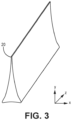
- FIG. 3 is a perspective view of insert 20 shown without tooling fixture 22. FIGS. 1-3 are discussed together.
- insert 20 can be assembled from a fibrous ceramic material.
- exemplary materials include two or three-dimensional woven, braided, knitted or non-textile (e.g., unidirectional short/long strand matted, etc.) ceramic (e.g., silicon carbide - SiC) structures.
- a polymer binder e.g., polyvinyl alcohol or polyvinyl butyral
- insert 20, with or without a binder can be placed into tooling fixture 22 which can include one or more segments 24.
- Each segment 24 can be machined such that, when assembled, tooling fixture 22 mirrors the dimensions of the specific preform cavity receiving insert 20. As such, tooling fixture 22 can help mold insert 20 into a more precise shape. Tooling fixture 22 further supports insert 20 during densification, as is discussed in greater detail below. Segments 24 can, accordingly, be formed from graphite, refractory metals, or a carbon-carbon composite, to name a few, non-limiting examples.
- One or more segments 24 can include infiltration holes (not visible in the plane of FIG. 2 ) to allow insert 20 to be infiltrated with reactant vapors during interface coating deposition and/or densification.
- the manner of assembly of insert 20 and fabrication and selection of tooling fixture 22 can be based upon a prior determination of the expected geometry of a preform void to create a suitable insert 20.
- insert 20 mounted within tooling fixture 22, can be infiltrated with a ceramic (e.g., SiC) matrix.
- matrix formation can be carried out using CVI.
- insert 20 is infiltrated by reactant vapors, and a gaseous precursor deposits on the ceramic fibers. Infiltration is carried out until reaching a desired porosity.
- insert 20 can be partially infiltrated, such that an amount of open porosity (i.e., above the desired final porosity) is present at the conclusion of step 16. This may be preferable to allow further infiltration of insert 20 once incorporated into a preform, which can improve bonding between insert 20 and the surrounding structure of the preform.
- a fully infiltrated insert 20 after step 16 can be preferable where very low insert porosity is desired, such as in CMC regions requiring high thermal conductivity and/or high oxidation resistance.
- Alternative methodologies for matrix formation can include, but are not limited to, one or a combination of melt infiltration (MI) or polymer infiltration and pyrolysis (PIP).
- MI melt infiltration
- PIP polymer infiltration and pyrolysis
- one or several interface coatings of a ceramic material e.g., of boron nitride - BN
- interface coatings can be deposited prior to formation of the ceramic matrix.
- interface coatings can be deposited at step 16, and densification can take place after the coated insert 20 is incorporated into a preform.
- insert 20 can optionally undergo post-infiltration processing.
- insert 20 has a three-dimensional geometry defined by a length along the z-axis, a height along the y-axis, and a width along the x-axis which varies along the height.
- Insert 20 has a somewhat triangular cross-sectional geometry with a slight concavity to each side in the x-y plane, but other geometries (e.g., four-sided, elliptical, combinations of straight and/or curved sides, etc.) are contemplated herein and would be selected to complement the shape of the preform void being occupied.
- One post-processing example can include removing insert 20 from tooling fixture 22 and trimming insert to a desired length.
- Tooling fixture 22 can be designed to accommodate a longer "blank” insert which can trimmed to a desired length and shape.
- tooling fixture 22 can be sized to accommodate an oversized "blank” that can be trimmed into multiple inserts 20, economically providing a prefabricated insert inventory for a plurality of preform variants.
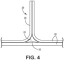
- FIG. 4 is a simplified cross-sectional illustration of a portion of preform 26 incorporating insert 20.
- Preform 26 is formed from various fibrous ceramic (e.g., SiC) plies 28, three of which are arranged in such manner as to form a pseudo-triangle or deltoid defining void 30 requiring reinforcement from insert 20.
- Plies 28 can be formed from braided, woven, and/or chopped ceramic fibers or tows.
- Voids 30 are common, for example, where plies 28 are folded and joined to form airfoils, platforms, flanges, etc., in CMC blades, vanes, rings, seals, etc. Additional plies 28 and/or other ceramic structures can also be included.
- Preform 26 incorporating one or more variously or uniformly shaped inserts 20 can be mounted within a tooling fixture (not shown) and undergo infiltration with an interface coating and/or ceramic matrix in a manner substantially similar to what is described with respect to step 16 above. Whereas traditional inserts can be insufficiently infiltrated with matrix compared to the remainder of the preform due to their individual thicknesses and more internal preform locations, prefabricated inserts 20 are already at least partially densified/rigidized prior to full preform densification. Thus, they can be infiltrated to the desired degree regardless of geometry and/or preform construction.
- a CMC component formed with the disclosed prefabricated inserts can be incorporated into components for multiple industries such as aerospace, maritime, or industrial, to name a few, non-limiting examples.
- a method of forming a ceramic matrix composite includes fabricating a space filling insert by assembling the space filling insert from a fibrous ceramic material, placing the space filling insert into a tooling fixture, the tooling fixture having an internal shape complementary to a shape of the insert, and infiltrating the space filling insert with a first ceramic material.
- the method further includes forming a preform by laying up a plurality of fibrous ceramic plies and inserting the infiltrated space filling insert into a void defined by the plurality of plies.
- the method further includes infiltrating the preform with a second ceramic material.
- At least one of the first ceramic material and the second ceramic material can be a ceramic matrix.
- the ceramic matrix comprises silicon carbide.
- At least one of the first ceramic material and the second ceramic material can be a ceramic interface coating.
- the steps of infiltrating each of the space filling insert and the preform can include one of: chemical vapor infiltration, polymer infiltration and pyrolysis, and melt infiltration.
- Any of the above methods can further include prior to placing the space filling insert into the tooling fixture, applying a polymer binder to the space filling insert.
- the tooling fixture can include a plurality of segments.
- At least one of the plurality of segments can include infiltration holes.
- the tooling fixture can be formed from one of graphite, a carbon-carbon composite, and a refractory metal.
- Any of the above methods can further include prior to fabricating the space filling insert, ascertaining an expected geometry of the void, and assembling the tooling fixture such that the internal shape substantially matches the expected shape of the void.
- a method of fabricating a space filling insert for a ceramic matrix composite includes assembling the space filling insert from a fibrous ceramic material, placing the space filling insert into a tooling fixture, the tooling fixture having an internal shape complementary to a shape of the insert, and infiltrating the space filling insert with a material.
- the fibrous ceramic material can include silicon carbide.
- the material can form one of a ceramic interface coating and a ceramic matrix.
- the ceramic matrix can include silicon carbide.
- Any of the above methods can further include prior to placing the space filling insert into the tooling fixture, applying a polymer binder to the space filling insert.
- Any of the above methods can further include after infiltrating the space filling insert, removing the space filling insert from the tooling fixture, and trimming the space filling insert.
- the tooling fixture can include a plurality of segments.
- At least one of the plurality of segments can include infiltration holes.
- the tooling fixture can be formed from one of graphite, a carbon-carbon composite, and a refractory metal.
- the step of infiltrating the space filling insert comprises one of: chemical vapor infiltration, polymer infiltration and pyrolysis, and melt infiltration.
Landscapes
- Chemical & Material Sciences (AREA)
- Engineering & Computer Science (AREA)
- Ceramic Engineering (AREA)
- Manufacturing & Machinery (AREA)
- Materials Engineering (AREA)
- Structural Engineering (AREA)
- Organic Chemistry (AREA)
- Inorganic Chemistry (AREA)
- Chemical Kinetics & Catalysis (AREA)
- General Chemical & Material Sciences (AREA)
- Mechanical Engineering (AREA)
- Ceramic Products (AREA)
Abstract
A method of forming a ceramic matrix composite includes fabricating a space filling insert (20) by assembling the space filling insert (20) from a fibrous ceramic material, placing the space filling insert (20) into a tooling fixture (22), the tooling fixture (22) having an internal shape complementary to a shape of the insert (20), and infiltrating the space filling insert (20) with a first ceramic material. The method further includes forming a preform by laying up a plurality of fibrous ceramic plies and inserting the infiltrated space filling insert (20) into a void defined by the plurality of plies. The method further includes infiltrating the preform with a second ceramic material.
Description
- The present invention relates to ceramic matrix composites and, more particularly, space filling inserts for use in ceramic matrix composite preforms.
- Many ceramic matrix composite (CMC) components for gas turbine engines have regions of variable wall thickness. Some of these regions are too small to form with textile-based plies, but too large to form using individual fiber tows. In such cases, space filling inserts can be used to build upon and prevent large voids in the body of the CMC. As with other locally thickened regions of CMCs, these inserts can often present challenges in achieving a high and/or uniform density through chemical vapor infiltration (CVI) or other infiltration processes.
- A method of forming a ceramic matrix composite includes fabricating a space filling insert by assembling the space filling insert from a fibrous ceramic material, placing the space filling insert into a tooling fixture, the tooling fixture having an internal shape complementary to a shape of the insert, and infiltrating the space filling insert with a first ceramic material. The method further includes forming a preform by laying up a plurality of fibrous ceramic plies and inserting the infiltrated space filling insert into a void defined by the plurality of plies. The method further includes infiltrating the preform with a second ceramic material.
- A method of fabricating a space filling insert for a ceramic matrix composite includes assembling the space filling insert from a fibrous ceramic material, placing the space filling insert into a tooling fixture, the tooling fixture having an internal shape complementary to a shape of the insert, and infiltrating the space filling insert with a material.
- Features of embodiments are set forth in the dependent claims.
-
-
FIG. 1 is a flowchart illustrating select steps of a method for fabricating a space filling insert for a preform. -
FIG. 2 is a front view of a space filling insert mounted within a tooling fixture. -
FIG. 3 is a perspective view of the space filling insert. -
FIG. 4 is a simplified cross-sectional view of a preform incorporating a space-filing insert. - While the above-identified figures set forth one or more embodiments of the present disclosure, other embodiments are also contemplated, as noted in the discussion. In all cases, this disclosure presents the invention by way of representation and not limitation. It should be understood that numerous other modifications and embodiments can be devised by those skilled in the art, which fall within the scope and spirit of the principles of the invention. The figures may not be drawn to scale, and applications and embodiments of the present invention may include features and components not specifically shown in the drawings.
- This disclosure presents prefabricated space filling inserts, sometimes referred to as "noodles," for incorporation into a CMC preform. More specifically, space filling inserts can be at least partially densified with a matrix prior to incorporation into a preform. This allows for fabrication of CMC components with more uniformly deposited matrixes.
-
FIG. 1 is a method flowchart illustrating steps 12-18 ofmethod 10 for fabricating an insert.FIG. 2 is front view ofinsert 20 mounted withintooling fixture 22.FIG. 3 is a perspective view ofinsert 20 shown without toolingfixture 22.FIGS. 1-3 are discussed together. - At
step 12,insert 20 can be assembled from a fibrous ceramic material. Exemplary materials include two or three-dimensional woven, braided, knitted or non-textile (e.g., unidirectional short/long strand matted, etc.) ceramic (e.g., silicon carbide - SiC) structures. A polymer binder (e.g., polyvinyl alcohol or polyvinyl butyral) can optionally be applied to the ceramic material to rigidizeinsert 20. - At
step 14, insert 20, with or without a binder, can be placed intotooling fixture 22 which can include one ormore segments 24. Eachsegment 24 can be machined such that, when assembled,tooling fixture 22 mirrors the dimensions of the specific preformcavity receiving insert 20. As such,tooling fixture 22 can help mold insert 20 into a more precise shape.Tooling fixture 22 further supports insert 20 during densification, as is discussed in greater detail below.Segments 24 can, accordingly, be formed from graphite, refractory metals, or a carbon-carbon composite, to name a few, non-limiting examples. One ormore segments 24 can include infiltration holes (not visible in the plane ofFIG. 2 ) to allowinsert 20 to be infiltrated with reactant vapors during interface coating deposition and/or densification. The manner of assembly ofinsert 20 and fabrication and selection oftooling fixture 22 can be based upon a prior determination of the expected geometry of a preform void to create asuitable insert 20. - At
step 16, insert 20, mounted withintooling fixture 22, can be infiltrated with a ceramic (e.g., SiC) matrix. In one embodiment, matrix formation can be carried out using CVI. During matrix formation,insert 20 is infiltrated by reactant vapors, and a gaseous precursor deposits on the ceramic fibers. Infiltration is carried out until reaching a desired porosity. In one embodiment,insert 20 can be partially infiltrated, such that an amount of open porosity (i.e., above the desired final porosity) is present at the conclusion ofstep 16. This may be preferable to allow further infiltration ofinsert 20 once incorporated into a preform, which can improve bonding betweeninsert 20 and the surrounding structure of the preform. A fully infiltratedinsert 20 afterstep 16 can be preferable where very low insert porosity is desired, such as in CMC regions requiring high thermal conductivity and/or high oxidation resistance. Alternative methodologies for matrix formation can include, but are not limited to, one or a combination of melt infiltration (MI) or polymer infiltration and pyrolysis (PIP). In some embodiments, one or several interface coatings of a ceramic material (e.g., of boron nitride - BN) can be deposited prior to formation of the ceramic matrix. In some other embodiments, interface coatings can deposited atstep 16, and densification can take place after the coatedinsert 20 is incorporated into a preform. - At
step 18,insert 20 can optionally undergo post-infiltration processing. As shown inFIG. 3 ,insert 20 has a three-dimensional geometry defined by a length along the z-axis, a height along the y-axis, and a width along the x-axis which varies along the height.Insert 20 has a somewhat triangular cross-sectional geometry with a slight concavity to each side in the x-y plane, but other geometries (e.g., four-sided, elliptical, combinations of straight and/or curved sides, etc.) are contemplated herein and would be selected to complement the shape of the preform void being occupied. One post-processing example can include removinginsert 20 fromtooling fixture 22 and trimming insert to a desired length.Tooling fixture 22 can be designed to accommodate a longer "blank" insert which can trimmed to a desired length and shape. In some examples,tooling fixture 22 can be sized to accommodate an oversized "blank" that can be trimmed intomultiple inserts 20, economically providing a prefabricated insert inventory for a plurality of preform variants. -
FIG. 4 is a simplified cross-sectional illustration of a portion ofpreform 26 incorporatinginsert 20.Preform 26 is formed from various fibrous ceramic (e.g., SiC)plies 28, three of which are arranged in such manner as to form a pseudo-triangle ordeltoid defining void 30 requiring reinforcement frominsert 20.Plies 28 can be formed from braided, woven, and/or chopped ceramic fibers or tows.Voids 30 are common, for example, whereplies 28 are folded and joined to form airfoils, platforms, flanges, etc., in CMC blades, vanes, rings, seals, etc.Additional plies 28 and/or other ceramic structures can also be included. Preform 26 incorporating one or more variously or uniformlyshaped inserts 20 can be mounted within a tooling fixture (not shown) and undergo infiltration with an interface coating and/or ceramic matrix in a manner substantially similar to what is described with respect tostep 16 above. Whereas traditional inserts can be insufficiently infiltrated with matrix compared to the remainder of the preform due to their individual thicknesses and more internal preform locations,prefabricated inserts 20 are already at least partially densified/rigidized prior to full preform densification. Thus, they can be infiltrated to the desired degree regardless of geometry and/or preform construction. - A CMC component formed with the disclosed prefabricated inserts can be incorporated into components for multiple industries such as aerospace, maritime, or industrial, to name a few, non-limiting examples.
- The following are non-exclusive descriptions of possible embodiments of the present invention.
- A method of forming a ceramic matrix composite includes fabricating a space filling insert by assembling the space filling insert from a fibrous ceramic material, placing the space filling insert into a tooling fixture, the tooling fixture having an internal shape complementary to a shape of the insert, and infiltrating the space filling insert with a first ceramic material. The method further includes forming a preform by laying up a plurality of fibrous ceramic plies and inserting the infiltrated space filling insert into a void defined by the plurality of plies. The method further includes infiltrating the preform with a second ceramic material.
- The method of the preceding paragraph can optionally include, additionally and/or alternatively, any one or more of the following features, configurations and/or additional steps:
In the above method, at least one of the first ceramic material and the second ceramic material can be a ceramic matrix. - In any of the above methods, the ceramic matrix comprises silicon carbide.
- In any of the above methods, at least one of the first ceramic material and the second ceramic material can be a ceramic interface coating.
- In any of the above methods, the steps of infiltrating each of the space filling insert and the preform can include one of: chemical vapor infiltration, polymer infiltration and pyrolysis, and melt infiltration.
- Any of the above methods can further include prior to placing the space filling insert into the tooling fixture, applying a polymer binder to the space filling insert.
- In any of the above methods, the tooling fixture can include a plurality of segments.
- In any of the above methods, at least one of the plurality of segments can include infiltration holes.
- In any of the above methods, the tooling fixture can be formed from one of graphite, a carbon-carbon composite, and a refractory metal.
- Any of the above methods can further include prior to fabricating the space filling insert, ascertaining an expected geometry of the void, and assembling the tooling fixture such that the internal shape substantially matches the expected shape of the void.
- A method of fabricating a space filling insert for a ceramic matrix composite includes assembling the space filling insert from a fibrous ceramic material, placing the space filling insert into a tooling fixture, the tooling fixture having an internal shape complementary to a shape of the insert, and infiltrating the space filling insert with a material.
- The method of the preceding paragraph can optionally include, additionally and/or alternatively, any one or more of the following features, configurations and/or additional steps:
In the above method, the fibrous ceramic material can include silicon carbide. - In any of the above methods, the material can form one of a ceramic interface coating and a ceramic matrix.
- In any of the above methods, the ceramic matrix can include silicon carbide.
- Any of the above methods can further include prior to placing the space filling insert into the tooling fixture, applying a polymer binder to the space filling insert.
- Any of the above methods can further include after infiltrating the space filling insert, removing the space filling insert from the tooling fixture, and trimming the space filling insert.
- In any of the above methods, the tooling fixture can include a plurality of segments.
- In any of the above methods, at least one of the plurality of segments can include infiltration holes.
- In any of the above methods, the tooling fixture can be formed from one of graphite, a carbon-carbon composite, and a refractory metal.
- In any of the above methods, the step of infiltrating the space filling insert comprises one of: chemical vapor infiltration, polymer infiltration and pyrolysis, and melt infiltration.
- While the invention has been described with reference to an exemplary embodiment(s), it will be understood by those skilled in the art that various changes may be made and equivalents may be substituted for elements thereof without departing from the scope of the invention. In addition, many modifications may be made to adapt a particular situation or material to the teachings of the invention without departing from the essential scope thereof. Therefore, it is intended that the invention should not be limited to the particular embodiment(s) disclosed, but that the invention will include all embodiments falling within the scope of the appended claims.
Claims (15)
- A method of fabricating a space filling insert (20) for a ceramic matrix composite, the method comprising:assembling the space filling insert (20) from a fibrous ceramic material;placing the space filling insert (20) into a tooling fixture (22), the tooling fixture (22) having an internal shape complementary to a shape of the insert (20); andinfiltrating the space filling insert (200 with a material.
- The method of claim 1, wherein the fibrous ceramic material comprises silicon carbide.
- The method of claim 1 or 2, wherein the material forms one of a ceramic interface coating and a ceramic matrix, optionally wherein the ceramic matrix comprises silicon carbide.
- The method of any preceding claim and further comprising: prior to placing the space filling insert (20) into the tooling fixture (22), applying a polymer binder to the space filling insert (20).
- The method of any preceding claim and further comprising: after infiltrating the space filling insert (20), removing the space filling insert (20) from the tooling fixture (22), and trimming the space filling insert (20).
- The method of any preceding claim, wherein the step of infiltrating the space filling insert (20) comprises one of: chemical vapor infiltration, polymer infiltration and pyrolysis, and melt infiltration.
- A method of forming a ceramic matrix composite, the method comprising:the method of fabricating a space filling insert (20) as recited in claim 1, wherein the material is a first ceramic material;forming a preform (26) by:laying up a plurality of fibrous ceramic plies (28); andinserting the infiltrated space filling insert (20) into a void (30) defined by the plurality of plies (28) ; andinfiltrating the preform (26) with a second ceramic material.
- The method of claim 7, wherein at least one of the first ceramic material and the second ceramic material is a ceramic matrix, optionally wherein the ceramic matrix comprises silicon carbide.
- The method of claim 7 or 8, wherein at least one of the first ceramic material and the second ceramic material is a ceramic interface coating.
- The method of any of claims 7 to 9, wherein the steps of infiltrating each of the space filling insert (20) and the preform (26) comprise one of: chemical vapor infiltration, polymer infiltration and pyrolysis, and melt infiltration.
- The method of any or claims 7 to 10 and further comprising: prior to placing the space filling insert (20) into the tooling fixture (22), applying a polymer binder to the space filling insert (20).
- The method of any preceding claim, wherein the tooling fixture (22) comprises a plurality of segments (24).
- The method of claim 12, wherein at least one of the plurality of segments (24) comprises infiltration holes.
- The method of any preceding claim, wherein the tooling fixture (22) is formed from one of graphite, a carbon-carbon composite, and a refractory metal.
- The method of claim 7 or any of claims 8 to 14 as dependent, directly or indirectly, on claim 7 and further comprising:
prior to fabricating the space filling insert (20):ascertaining an expected geometry of the void (30); andassembling the tooling fixture (22) such that the internal shape substantially matches the expected shape of the void (30).
Applications Claiming Priority (1)
| Application Number | Priority Date | Filing Date | Title |
|---|---|---|---|
| US18/196,594 US20240376017A1 (en) | 2023-05-12 | 2023-05-12 | Prefabricated noodle |
Publications (1)
| Publication Number | Publication Date |
|---|---|
| EP4470992A1 true EP4470992A1 (en) | 2024-12-04 |
Family
ID=91067238
Family Applications (1)
| Application Number | Title | Priority Date | Filing Date |
|---|---|---|---|
| EP24174837.5A Pending EP4470992A1 (en) | 2023-05-12 | 2024-05-08 | Prefabricated noodle |
Country Status (2)
| Country | Link |
|---|---|
| US (1) | US20240376017A1 (en) |
| EP (1) | EP4470992A1 (en) |
Citations (3)
| Publication number | Priority date | Publication date | Assignee | Title |
|---|---|---|---|---|
| US20190359531A1 (en) * | 2018-05-23 | 2019-11-28 | Rolls-Royce High Temperature Composites Inc. | Method of making a fiber preform for ceramic matrix composite (cmc) fabrication |
| US10906842B2 (en) * | 2018-10-18 | 2021-02-02 | Rolls-Royce High Temperature Composites Inc. | Method of processing a ceramic matrix composite (CMC) component |
| EP4134357A1 (en) * | 2021-08-12 | 2023-02-15 | Raytheon Technologies Corporation | Ceramic particle based inserts for cmc |
Family Cites Families (25)
| Publication number | Priority date | Publication date | Assignee | Title |
|---|---|---|---|---|
| DE19856809A1 (en) * | 1998-12-09 | 2000-06-15 | Hoffmann Elektrokohle | Process for impregnating porous workpieces |
| DE10229297A1 (en) * | 2002-06-29 | 2004-01-15 | Komage-Gellner Maschinenfabrik Kg | Method and device for producing a molding |
| US7223465B2 (en) * | 2004-12-29 | 2007-05-29 | General Electric Company | SiC/SiC composites incorporating uncoated fibers to improve interlaminar strength |
| US8034136B2 (en) * | 2006-11-20 | 2011-10-11 | Us Synthetic Corporation | Methods of fabricating superabrasive articles |
| US20090165924A1 (en) * | 2006-11-28 | 2009-07-02 | General Electric Company | Method of manufacturing cmc articles having small complex features |
| US7832972B2 (en) * | 2008-03-05 | 2010-11-16 | United Technologies Corporation | Internal pocket fastener system for ceramic matrix composites |
| US8714485B2 (en) * | 2009-12-15 | 2014-05-06 | The Boeing Company | Method of fabricating a hat stringer |
| US8899939B2 (en) * | 2009-12-23 | 2014-12-02 | General Electric Company | Process for producing a ceramic matrix composite article and article formed thereby |
| CN102834210A (en) * | 2010-04-08 | 2012-12-19 | 株式会社图格莱 | Composite body |
| US9103214B2 (en) * | 2011-08-23 | 2015-08-11 | United Technologies Corporation | Ceramic matrix composite vane structure with overwrap for a gas turbine engine |
| US9429202B2 (en) * | 2012-05-02 | 2016-08-30 | Intellectuall Property Holdings LLC | Ceramic preform and method |
| US20160185009A1 (en) * | 2014-12-29 | 2016-06-30 | Smith International, Inc. | Additive manufacturing of composite molds |
| US10370997B2 (en) * | 2015-05-26 | 2019-08-06 | Rolls-Royce Corporation | Turbine shroud having ceramic matrix composite seal segment |
| GB201513236D0 (en) * | 2015-07-28 | 2015-09-09 | Rolls Royce Plc | A nozzle guide vane passage |
| US10995040B2 (en) * | 2016-03-14 | 2021-05-04 | Rolls-Royce High Temperature Composites, Inc. | Ceramic matrix composite components having a deltoid region and methods for fabricating the same |
| US11518714B2 (en) * | 2016-09-16 | 2022-12-06 | Max Sardou | Method for manufacturing an elastic ceramic matrix composite |
| US10144675B2 (en) * | 2016-10-24 | 2018-12-04 | Honeywell International Inc. | Segmented carbon fiber preform |
| US10717116B2 (en) * | 2017-05-01 | 2020-07-21 | Rolls-Royce High Temperature Composites Inc. | Method of slurry infiltration and cleaning to fabricate a ceramic matrix composite (CMC) component with an internal cavity or bore |
| US11623366B2 (en) * | 2017-12-15 | 2023-04-11 | Rolls-Royce Corporation | Tooling inserts for ceramic matrix composites |
| KR102720128B1 (en) * | 2018-01-19 | 2024-10-23 | 알바니 엔지니어드 콤포짓스, 인크. | Method for manufacturing ceramic matrix composites |
| US11015467B2 (en) * | 2018-07-06 | 2021-05-25 | Raytheon Technologies Corporation | Porous space fillers for ceramic matrix composites |
| US11434177B2 (en) * | 2019-05-13 | 2022-09-06 | Rolls-Royce Plc | Ceramic matrix composite vane with hybrid construction |
| US20210331387A1 (en) * | 2020-04-28 | 2021-10-28 | Baker Hughes Oilfield Operations Llc | Additive manufacture of barrier sleeve inserts for sintered bits |
| US12157708B2 (en) * | 2021-05-07 | 2024-12-03 | Rtx Corporation | Method for creating cooling holes in a CMC laminate |
| US11773730B2 (en) * | 2021-10-22 | 2023-10-03 | Rolls-Royce Plc | Ceramic matrix composite airfoil with heat transfer augmentation |
-
2023
- 2023-05-12 US US18/196,594 patent/US20240376017A1/en active Pending
-
2024
- 2024-05-08 EP EP24174837.5A patent/EP4470992A1/en active Pending
Patent Citations (3)
| Publication number | Priority date | Publication date | Assignee | Title |
|---|---|---|---|---|
| US20190359531A1 (en) * | 2018-05-23 | 2019-11-28 | Rolls-Royce High Temperature Composites Inc. | Method of making a fiber preform for ceramic matrix composite (cmc) fabrication |
| US10906842B2 (en) * | 2018-10-18 | 2021-02-02 | Rolls-Royce High Temperature Composites Inc. | Method of processing a ceramic matrix composite (CMC) component |
| EP4134357A1 (en) * | 2021-08-12 | 2023-02-15 | Raytheon Technologies Corporation | Ceramic particle based inserts for cmc |
Also Published As
| Publication number | Publication date |
|---|---|
| US20240376017A1 (en) | 2024-11-14 |
Similar Documents
| Publication | Publication Date | Title |
|---|---|---|
| RU2523308C2 (en) | Production of turbomachine blade from composite | |
| US8714932B2 (en) | Ceramic matrix composite blade having integral platform structures and methods of fabrication | |
| US9080454B2 (en) | Composite material turbine engine vane, and method for manufacturing same | |
| CN102971135B (en) | There is the turbine set blade of complementary non-symmetrical geometries | |
| EP1676822B1 (en) | SiC/SiC composites incorporating uncoated fibers to improve interlaminar strength | |
| EP3109043B1 (en) | Method for integral joining infiltrated ceramic matrix composites | |
| EP2540975A2 (en) | Hybrid part made from monolithic ceramic skin and cmc core | |
| CN108699916A (en) | Ceramic matrix composite turbine machine component with classification fiber reinforced ceramic-base bottom | |
| US20230192561A1 (en) | Controlled gradient of porosity in cmc | |
| US20160214283A1 (en) | Composite tool and method for forming composite components | |
| EP1674599A2 (en) | Orthogonal weaving for fabricating complex shape preforms | |
| EP2006487A1 (en) | Method of manufaturing CMC articles having small complex features | |
| CA2921263C (en) | Laminate structure fabricated using chemical vapor infiltration (cvi) | |
| EP4414345A1 (en) | Composite panels and methods for manufacturing the same | |
| US12385404B2 (en) | Blade made of composite material with at least partially ceramic matrix | |
| US20160158964A1 (en) | Ceramic-encapsulated thermopolymer pattern or support with metallic plating | |
| US20240376017A1 (en) | Prefabricated noodle | |
| EP3760604B1 (en) | Method of forming cooling channels in a ceramic matrix composite component | |
| EP4470740A1 (en) | Additively manufactured graphite tooling | |
| EP4549146B1 (en) | Pre-shaped space fillers for small cross section features | |
| EP3738768A1 (en) | Rapid processing of laminar composite components |
Legal Events
| Date | Code | Title | Description |
|---|---|---|---|
| PUAI | Public reference made under article 153(3) epc to a published international application that has entered the european phase |
Free format text: ORIGINAL CODE: 0009012 |
|
| STAA | Information on the status of an ep patent application or granted ep patent |
Free format text: STATUS: THE APPLICATION HAS BEEN PUBLISHED |
|
| AK | Designated contracting states |
Kind code of ref document: A1 Designated state(s): AL AT BE BG CH CY CZ DE DK EE ES FI FR GB GR HR HU IE IS IT LI LT LU LV MC ME MK MT NL NO PL PT RO RS SE SI SK SM TR |
|
| STAA | Information on the status of an ep patent application or granted ep patent |
Free format text: STATUS: REQUEST FOR EXAMINATION WAS MADE |
|
| 17P | Request for examination filed |
Effective date: 20250530 |