EP4470919A2 - Next gen passenger service unit - Google Patents
Next gen passenger service unit Download PDFInfo
- Publication number
- EP4470919A2 EP4470919A2 EP24179527.7A EP24179527A EP4470919A2 EP 4470919 A2 EP4470919 A2 EP 4470919A2 EP 24179527 A EP24179527 A EP 24179527A EP 4470919 A2 EP4470919 A2 EP 4470919A2
- Authority
- EP
- European Patent Office
- Prior art keywords
- air
- coupled
- assembly
- ion emitter
- control unit
- Prior art date
- Legal status (The legal status is an assumption and is not a legal conclusion. Google has not performed a legal analysis and makes no representation as to the accuracy of the status listed.)
- Granted
Links
Images




Classifications
-
- B—PERFORMING OPERATIONS; TRANSPORTING
- B64—AIRCRAFT; AVIATION; COSMONAUTICS
- B64D—EQUIPMENT FOR FITTING IN OR TO AIRCRAFT; FLIGHT SUITS; PARACHUTES; ARRANGEMENT OR MOUNTING OF POWER PLANTS OR PROPULSION TRANSMISSIONS IN AIRCRAFT
- B64D13/00—Arrangements or adaptations of air-treatment apparatus for aircraft crew or passengers, or freight space
- B64D13/06—Arrangements or adaptations of air-treatment apparatus for aircraft crew or passengers, or freight space the air being conditioned
-
- A—HUMAN NECESSITIES
- A61—MEDICAL OR VETERINARY SCIENCE; HYGIENE
- A61L—METHODS OR APPARATUS FOR STERILISING MATERIALS OR OBJECTS IN GENERAL; DISINFECTION, STERILISATION OR DEODORISATION OF AIR; CHEMICAL ASPECTS OF BANDAGES, DRESSINGS, ABSORBENT PADS OR SURGICAL ARTICLES; MATERIALS FOR BANDAGES, DRESSINGS, ABSORBENT PADS OR SURGICAL ARTICLES
- A61L9/00—Disinfection, sterilisation or deodorisation of air
- A61L9/16—Disinfection, sterilisation or deodorisation of air using physical phenomena
- A61L9/22—Ionisation
-
- F—MECHANICAL ENGINEERING; LIGHTING; HEATING; WEAPONS; BLASTING
- F24—HEATING; RANGES; VENTILATING
- F24F—AIR-CONDITIONING; AIR-HUMIDIFICATION; VENTILATION; USE OF AIR CURRENTS FOR SCREENING
- F24F8/00—Treatment, e.g. purification, of air supplied to human living or working spaces otherwise than by heating, cooling, humidifying or drying
- F24F8/30—Treatment, e.g. purification, of air supplied to human living or working spaces otherwise than by heating, cooling, humidifying or drying by ionisation
-
- A—HUMAN NECESSITIES
- A61—MEDICAL OR VETERINARY SCIENCE; HYGIENE
- A61L—METHODS OR APPARATUS FOR STERILISING MATERIALS OR OBJECTS IN GENERAL; DISINFECTION, STERILISATION OR DEODORISATION OF AIR; CHEMICAL ASPECTS OF BANDAGES, DRESSINGS, ABSORBENT PADS OR SURGICAL ARTICLES; MATERIALS FOR BANDAGES, DRESSINGS, ABSORBENT PADS OR SURGICAL ARTICLES
- A61L2209/00—Aspects relating to disinfection, sterilisation or deodorisation of air
- A61L2209/10—Apparatus features
- A61L2209/14—Filtering means
-
- B—PERFORMING OPERATIONS; TRANSPORTING
- B64—AIRCRAFT; AVIATION; COSMONAUTICS
- B64D—EQUIPMENT FOR FITTING IN OR TO AIRCRAFT; FLIGHT SUITS; PARACHUTES; ARRANGEMENT OR MOUNTING OF POWER PLANTS OR PROPULSION TRANSMISSIONS IN AIRCRAFT
- B64D13/00—Arrangements or adaptations of air-treatment apparatus for aircraft crew or passengers, or freight space
- B64D13/06—Arrangements or adaptations of air-treatment apparatus for aircraft crew or passengers, or freight space the air being conditioned
- B64D2013/0603—Environmental Control Systems
- B64D2013/067—Environmental Control Systems with air ionizers
Definitions
- the present disclosure generally relates to systems for managing air quality in an aircraft, and more specifically, to using air ionizers in an aircraft.
- Circulation of air within an enclosed space may include circulation of harmful pathogens (e.g., viruses, bacteria, etc.) and undesirable odors.
- pathogens e.g., viruses, bacteria, etc.
- HEPA high efficiency particulate air
- air filters are placed at central locations and therefore may not have continuous effectiveness within the enclosed space.
- more effective air filters, such as HEPA filters come with an increased cost both in terms of the replaceable filter itself as well as the energy used to force air through the air filter.
- air filters, including HEPA filters typically do not remove odors from the air within the enclosed space.
- the passenger service unit includes an air outlet assembly, a control unit electronically coupled to the air distribution box, an air gasper assembly coupled to the air distribution box, and an ion emitter coupled to the air gasper assembly and electronically coupled to the control unit, wherein the ion emitter is configured to be controlled by the control unit.
- the ion emitter is configured to be in an air flow passing through the air gasper assembly. In various embodiments, the ion emitter is perpendicular to the air flow passing through the air gasper assembly. In various embodiments, the air gasper assembly includes a base, a shield coupled to the base, and a spoke coupled to the base and the shield, wherein the ion emitter is coupled to the spoke.
- the passenger service unit further includes a plurality of ion emitters arranged around a circumference of the spoke, each of the plurality of ion emitters being perpendicular to a flow of air passing through the air gasper assembly.
- the passenger service unit further includes a wire coupled to the spoke and configured to pass an electric voltage from the control unit to the ion emitter.
- the control unit includes a voltage input having a first voltage and a voltage output having a second voltage that is greater than the first voltage, the voltage output being coupled to the ion emitter.
- an aircraft including a passenger seat and a passenger service unit installed over the passenger seat.
- the passenger service unit includes an air distribution box, a control unit electronically coupled to the air outlet assembly, an air gasper assembly coupled to the air distribution box, and an ion emitter coupled to the air gasper assembly and electronically coupled to the control unit, wherein the ion emitter is configured to be controlled by the control unit.
- aircraft cabin section 200 may be an example of first cabin section 118, second cabin section 120, and/or third cabin section 122.
- Aircraft cabin section 200 includes a plurality of passenger seats 202, a plurality of passenger service units 204, and a plurality of ion emitters 206 disposed within the plurality of passenger service units 204, and an air conditioning duct 208 disposed above and coupled to the plurality of passenger service units 204.
- First air outlet assembly 302 and second air outlet assembly 304 are coupled to a top surface (e.g., in the positive z-direction) of infill panel and are located above the passengers' seats (e.g., passenger seats 202) and coupled to an air condition duct (e.g., air conditioning duct 208).
- a top surface e.g., in the positive z-direction
- passengers' seats e.g., passenger seats 202
- an air condition duct e.g., air conditioning duct 208
- Control unit 308 is logically and electrically coupled to ion emitter 312 by wiring 310.
- Ion emitters 312 are coupled to first air distribution box 302 and second air distribution box 304.
- Control unit 308 controls each ion emitters 312 by adjusting a voltage, a current, a timing, and/or other parameters to increase or decrease a number of ions produced by each ion emitters 312. In various embodiments, increasing a voltage and/or a current to each ion emitters 312 increases the number of ions produced by ion emitters 312. In various embodiments, decreasing the voltage and/or the current to each ion emitters 312 decreases the number of ions produced by ion emitter 312.
- Air outlet assembly 400 includes an air distribution box410, a lower portion 412, air inlets 414, and one or more mount points 416 for mounting ion emitters 404.
- Air distribution box 410 defines a cavity 418 into which air flows from air inlets 414. Air flows through air inlets 414, into cavity 418, and out through one or more air gasper assemblies 402.
- Air distribution box 410 is configured to be coupled to lower portion 412. Lower portion 412 is configured to couple to infill panel 306.
- Air gasper assemblies 402 are configured to extend downward (e.g., in the negative z-direction) toward passengers and passenger seats (e.g., passenger seats 202).
- An opening 420 is formed in lower portion 412 for each air gasper assembly 402.
- Air gasper assembly 402 includes a base 422, a shield 424, and a spoke 426.
- Base 422 is coupled to lower portion 412, and more specifically, to opening 420 within lower portion 412.
- base 422 is configured to allow movement so that a passenger may position the flow of air in a desired direction.
- Shield 424 and spoke 426 are coupled to base 422 and work together to increase or decrease the flow of air through air gasper assembly 402.
- shield 424 is rotatably coupled to base 422 around spoke 426 so that rotating shield 424 in a first direction (e.g., counterclockwise) increases a flow of air and rotating shield 424 in a second direction (e.g., clockwise) decreases the flow of air.
- one or more ion emitters 404 are mounted to air distribution box410 of air outlet assembly 400 (as illustrated in FIG. 3 ) and extend into cavity 418. In various embodiments, one or more ion emitters 404 are mounted to air inlet 414 (as illustrated in FIGS. 4A and 4B ) and extend into cavity 418. Each of the ion emitters 404 mounted to upper portion 410 are connected to control unit 308 by wiring 310.
- ion emitter 404 may be radially placed at a non-perpendicular angle to a direction of an air flow.
- Air gasper assembly 402 further includes a wire 428 coupled to base 422 and extending through spoke 426 to each ion emitter 404. Wire 428 is connected to control unit 308.
- ion emitters 404 at the air outlet rather than a central air controller, provides the ionized air flow in close proximity to where it may benefit passengers. There are fewer surfaces between ion emitters 404 and the passengers to which the ionized air may attach itself. This is important as the ions in the air flow, and thus the ionized air flow, has a low residence time (i.e., low life span) that is about 20 seconds to about 60 seconds.
- GUI 500 includes an options menu 502, a cabin area selector 504, a scene selector 506, a current scene indicator 508, an all areas button 510, a start button 512, a hold button 514, a resume button 516, and a timer 518.
- Options menu 502 provides a crew member the ability to control different aspects of the cabin including lighting, temperature, windows, and ion count and to view status of the cabin including attendant call button and water status.
- Cabin area selector 504 allow the crew member to select which cabin section to monitor such as business class, economy class forward, and economy class aft. Pressing all areas button 510 may select all cabin areas for adjustment.
- Selecting ion count 520 presents the crew member with scene selector 506 and current scene indicator 508.
- scene selector 506 may present the crew member with different scenes to adjust the number of ions being generated by air ionizers and ion emitters (e.g., ion emitter 404) within each cabin area.
- scene selector 506 presents the cabin crew with different options such as "Boarding/Deplane", "Take off / Landing", “Take off / Landing Night”, "High”, “High-Mid”, “Mid”, “Mid-Low”, “Low”, “Waterfall”, “Mountain”, “Seaside”, “Countryside”, “Custom1", “Custom2”, and “Custom3".
- the selections in scene selector 506 are intended to simplify the control of the air ionizers for the cabin crew.
- the different scenes may produce different numbers of ions depending on the current state of the cabin area.
- the cabin crew may select "Countryside” or “Low” in response to normal conditions within the cabin area.
- the cabin crew may select "High” or “Waterfall” in response to a malodor within the cabin area (e.g., a soiled diaper, garbage, lavatory, etc.). Doing so provides the cabin crew the ability to adjust the number of ions per cubic centimeter (ions/cc) to a level that is comfortable for the passengers by increasing or decreasing the voltage supplied to each ion emitter (e.g., ion emitter 404).
- Start button 512 may change the selected scene.
- Hold button 514 may pause the selected scene for a time.
- Resume button 516 may resume the selected scene after being on hold.
- Timer 518 may provide an indication of how long the selected scene has been running or on hold.
- System 600 includes a graphical user interface (GUI) 602, a controller 604, and ion emitters 606a-606c.
- GUI 602 may be an example of GUI 500 described above in FIG. 5 .
- controller 604 may be an example of control unit 308 described above in FIG. 3 .
- controller 604 may be an example of a central aircraft controller or other server.
- ion emitters 606a-606c may be examples of ion emitter 404 described in FIGS. 4A-4D .
- ion emitters 606a-606c may be examples of ion emitter 206 described above in FIG. 2 .
- Controller 604 includes a processor 608, a memory 610, and a voltage converter 612.
- Processor 608 is configured to communicate with GLTI 602 to receive commands from a crew member and to control ion emitters 606a-606c in response to the received commands.
- Memory 610 is configured to store data from GLTI 602 and processor 608.
- Voltage converter 612 is configured to receive commands from processor 608 and convert an input voltage (e.g., 28 VDC, 115 VAC) to a high voltage output (e.g., 10 kV DC) for use by ion emitters 606a-606c).
- Processor 608 may comprise one or more processors configured to implement various logical operations in response to execution of instructions, for example, instructions stored on a non-transitory, tangible, computer-readable medium.
- the one or more processors can be a general purpose processor, a microprocessor, a microcontroller, a digital signal processor (DSP), an application specific integrated circuit (ASIC), a field programmable gate array (FPGA) or other programmable logic device, discrete or transistor logic, discrete hardware components, or any combination thereof.
- Memory 610 may comprise memory to store data, executable instructions, system program instructions, and/or controller instructions to implement the control logic of processor 608.
- references to "one embodiment,” “an embodiment,” “various embodiments,” etc. indicate that the embodiment described may include a particular feature, structure, or characteristic, but every embodiment may not necessarily include the particular feature, structure, or characteristic. Moreover, such phrases are not necessarily referring to the same embodiment. Further, when a particular feature, structure, or characteristic is described in connection with an embodiment, it is submitted that it is within the knowledge of one skilled in the art to affect such feature, structure, or characteristic in connection with other embodiments whether or not explicitly described. After reading the description, it will be apparent to one skilled in the relevant art(s) how to implement the disclosure in alternative embodiments.
- Numbers, percentages, or other values stated herein are intended to include that value, and also other values that are about or approximately equal to the stated value, as would be appreciated by one of ordinary skill in the art encompassed by various embodiments of the present disclosure.
- a stated value should therefore be interpreted broadly enough to encompass values that are at least close enough to the stated value to perform a desired function or achieve a desired result.
- the stated values include at least the variation to be expected in a suitable industrial process, and may include values that are within 5% of a stated value.
- the terms “substantially,” “about” or “approximately” as used herein represent an amount close to the stated amount that still performs a desired function or achieves a desired result.
- the term “substantially,” “about” or “approximately” may refer to an amount that is within 5% of a stated amount or value.
Landscapes
- Health & Medical Sciences (AREA)
- Engineering & Computer Science (AREA)
- General Health & Medical Sciences (AREA)
- Mechanical Engineering (AREA)
- General Engineering & Computer Science (AREA)
- Chemical & Material Sciences (AREA)
- Epidemiology (AREA)
- Life Sciences & Earth Sciences (AREA)
- Animal Behavior & Ethology (AREA)
- Combustion & Propulsion (AREA)
- Public Health (AREA)
- Veterinary Medicine (AREA)
- Pulmonology (AREA)
- Aviation & Aerospace Engineering (AREA)
- Air-Conditioning For Vehicles (AREA)
Abstract
Description
- This application claims priority to, and the benefit of,
India Provisional Patent Application No. 202341038053, filed June 2, 2023 - The present disclosure generally relates to systems for managing air quality in an aircraft, and more specifically, to using air ionizers in an aircraft.
- Travel within aircraft includes the recirculation of air within the aircraft. Circulation of air within an enclosed space, such as aircraft, may include circulation of harmful pathogens (e.g., viruses, bacteria, etc.) and undesirable odors. Currently, commercial aircraft use air filters, including high efficiency particulate air (HEPA) filters, to filter the air during recirculation. Generally, air filters are placed at central locations and therefore may not have continuous effectiveness within the enclosed space. Furthermore, more effective air filters, such as HEPA filters, come with an increased cost both in terms of the replaceable filter itself as well as the energy used to force air through the air filter. Furthermore, air filters, including HEPA filters, typically do not remove odors from the air within the enclosed space.
- A passenger service unit is disclosed herein. The passenger service unit includes an air outlet assembly, a control unit electronically coupled to the air distribution box, an air gasper assembly coupled to the air distribution box, and an ion emitter coupled to the air gasper assembly and electronically coupled to the control unit, wherein the ion emitter is configured to be controlled by the control unit.
- In various embodiments, the ion emitter is configured to be in an air flow passing through the air gasper assembly. In various embodiments, the ion emitter is perpendicular to the air flow passing through the air gasper assembly. In various embodiments, the air gasper assembly includes a base, a shield coupled to the base, and a spoke coupled to the base and the shield, wherein the ion emitter is coupled to the spoke.
- In various embodiments, the passenger service unit further includes a plurality of ion emitters arranged around a circumference of the spoke, each of the plurality of ion emitters being perpendicular to a flow of air passing through the air gasper assembly. In various embodiments, the passenger service unit further includes a wire coupled to the spoke and configured to pass an electric voltage from the control unit to the ion emitter. In various embodiments, the control unit includes a voltage input having a first voltage and a voltage output having a second voltage that is greater than the first voltage, the voltage output being coupled to the ion emitter.
- Also disclosed herein is an aircraft including a passenger seat and a passenger service unit installed over the passenger seat. The passenger service unit includes an air distribution box, a control unit electronically coupled to the air outlet assembly, an air gasper assembly coupled to the air distribution box, and an ion emitter coupled to the air gasper assembly and electronically coupled to the control unit, wherein the ion emitter is configured to be controlled by the control unit.
- In various embodiments, the ion emitter is configured to be in an air flow passing through the air gasper assembly. In various embodiments, the ion emitter is perpendicular to the air flow passing through the air gasper assembly. In various embodiments, the air gasper assembly includes a base, a shield coupled to the base, and a spoke coupled to the base and the shield, wherein the ion emitter is coupled to the spoke. In various embodiments, the passenger service unit further includes a plurality of ion emitters arranged around a circumference of the spoke, each of the plurality of ion emitters being perpendicular to a flow of air passing through the air gasper assembly.
- In various embodiments, the control unit includes a voltage input having a first voltage and a voltage output having a second voltage that is greater than the first voltage, the voltage output being coupled to the ion emitter. In various embodiments, the aircraft further includes an air condition system that provides an air flow to the air distribution box, wherein the ion emitter ionizes the air flow through the air gasper assembly.
- Also disclosed herein is a system including an ion emitter, a graphical user interface, a control unit electronically coupled to the ion emitter, a processor electronically coupled to the control unit, and a memory operatively coupled to the processor, the memory comprising instructions stored thereon that, when executed by the processor, cause the processor to receive an input from the graphical user interface and send a signal to the control unit to adjust a voltage to the ion emitter in response to the input.
- In various embodiments, the signal includes an instruction to increase a voltage output from the control unit to the ion emitter to increase a number of ions produced by the ion emitter. In various embodiments, the signal includes an instruction to decrease a voltage output from the control unit to the ion emitter to decrease a number of ions produced by the ion emitter. In various embodiments, the control unit includes a voltage input configured to receive a first voltage and a voltage output configured to output a second voltage, the second voltage being greater than the first voltage.
- In various embodiments, the system further includes a passenger service unit, an air outlet assembly coupled to the passenger service unit, and an air gasper assembly coupled to the air distribution box, wherein the ion emitter is coupled to the air gasper assembly. In various embodiments, the control unit is coupled to the passenger service unit.
- The foregoing features and elements may be combined in any combination, without exclusivity, unless expressly indicated herein otherwise. These features and elements as well as the operation of the disclosed embodiments will become more apparent in light of the following description and accompanying drawings.
- The subject matter of the present disclosure is particularly pointed out and distinctly claimed in the concluding portion of the specification. A more complete understanding of the present disclosure, however, may best be obtained by referring to the following detailed description and claims in connection with the following drawings. While the drawings illustrate various embodiments employing the principles described herein, the drawings do not limit the scope of the claims.
-
FIG. 1 illustrates an aircraft and various sections within the aircraft, in accordance with various embodiments. -
FIG. 2 illustrates a cabin of an aircraft including passenger seats and air ionizers, in accordance with various embodiments. -
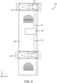
FIG. 3 illustrates a passenger service unit for use in a cabin of an aircraft, in accordance with various embodiments. -
FIGS. 4A, 4B ,4C, and 4D illustrate components of a passenger service unit for use in a cabin of an aircraft, in accordance with various embodiments. -
FIG. 5 illustrates a user interface for controlling an air ionizer in a passenger service unit, in accordance with various embodiments. -
FIG. 6 illustrates a system for controlling an air ionizer in a passenger service unit, in accordance with various embodiments. - The following detailed description of various embodiments herein makes reference to the accompanying drawings, which show various embodiments by way of illustration. While these various embodiments are described in sufficient detail to enable those skilled in the art to practice the disclosure, it should be understood that other embodiments may be realized and that changes may be made without departing from the scope of the disclosure. Thus, the detailed description herein is presented for purposes of illustration only and not of limitation. While these exemplary embodiments are described in sufficient detail to enable those skilled in the art to practice the invention, it should be understood that other embodiments may be realized and that logical, chemical and mechanical changes may be made without departing from the spirit and scope of the invention. For example, the steps recited in any of the method or process descriptions may be executed in any order and are not necessarily limited to the order presented. Furthermore, any reference to singular includes plural embodiments, and any reference to more than one component or step may include a singular embodiment or step. Also, any reference to attached, fixed, connected, or the like may include permanent, removable, temporary, partial, full or any other possible attachment option. Additionally, any reference to without contact (or similar phrases) may also include reduced contact or minimal contact. It should also be understood that unless specifically stated otherwise, references to "a," "an" or "the" may include one or more than one and that reference to an item in the singular may also include the item in the plural. Further, all ranges may include upper and lower values and all ranges and ratio limits disclosed herein may be combined.
- Disclosed herein is a system for ionizing air within an aircraft cabin. The system includes a control unit coupled to a passenger service unit (PSU) that is installed over one or more passenger seats. In various embodiments, each PSU includes one or more air outlet assemblies for controlling a flow of air over the passenger seats. In various embodiments, each air outlet assembly includes one or more air gasper assemblies to control the flow the of air. In various embodiments, one or more ion emitters may be coupled to each of the one or more air outlet assemblies. In various embodiments, each ion emitter is coupled to the control unit. In various embodiments, each ion emitter ionizes the air as it flows through the air gasper assembly. In various embodiments, the ionized air improves the quality of the air within the aircraft cabin.
- Referring now to
FIG. 1 , anaircraft 100 including various sections within the aircraft is illustrated, in accordance with various embodiments.Aircraft 100 is an example of a passenger or transport vehicle in which smart air ionizers may be implemented in accordance with various embodiments. In various embodiments,aircraft 100 has astarboard wing 102 and aport wing 104 attached to afuselage 106. In various embodiments,aircraft 100 also includes astarboard engine 108 connected to starboardwing 102 and aport engine 110 connected toport wing 104. In various embodiments,aircraft 100 also includes a starboardhorizontal stabilizer 112, a porthorizontal stabilizer 114, and avertical stabilizer 116. In various embodiments,aircraft 100 also includes various cabin sections, including, for example, afirst cabin section 118, asecond cabin section 120, athird cabin section 122, and apilot cabin 124. In various embodiments,cabin sections aircraft 100 may include afront lavatory 126 and/or arear lavatory 128. - Referring now to
FIG. 2 , a side view of anaircraft cabin section 200 of an aircraft (e.g., aircraft 100) is illustrated, in accordance with various embodiments. In various embodiments,aircraft cabin section 200 may be an example offirst cabin section 118,second cabin section 120, and/orthird cabin section 122.Aircraft cabin section 200 includes a plurality ofpassenger seats 202, a plurality ofpassenger service units 204, and a plurality ofion emitters 206 disposed within the plurality ofpassenger service units 204, and anair conditioning duct 208 disposed above and coupled to the plurality ofpassenger service units 204. - The plurality of
passenger seats 202 may be arranged in rows throughoutaircraft cabin section 200. In various embodiments, one or more aisles may pass through each row of the plurality of passenger seats 202. The plurality ofpassenger service units 204 are disposed over the plurality of passenger seats 202. In various embodiment, each of passenger service unit of the plurality ofpassenger service units 204 may include a light, an air outlet, one ormore ion emitters 206, and an attendant call button, among others. In various embodiments, the ion emitters are placed within a flow of air that passes throughair conditioning duct 208, the plurality ofpassenger service units 204, and through one or more air gaspers in the plurality ofpassenger service units 204. Eachion emitter 206 ionizes the air in the flow of air creating anionic region 210 over the plurality ofpassenger seats 202 that includespositive ions 212 and a plurality ofnegative ions 214. - In various embodiments,
ion emitter 206, and more specifically,positive ions 212 may neutralize pathogens (e.g., bacteria, viruses, molds, dust, etc.) and/or malodor (i.e., unpleasant smells) that are airborne and on surfaces. Pathogens and malodor may be generated and/or spread by passengers and activities throughoutaircraft 100 andcabin section 200, among other locations. Pathogens and malodor may be airborne and/or settle on surfaces withincabin section 200 andaircraft 100, among others.ion emitter 206 may be placed adjacent an air gasper so thation emitter 206 ionizes the air exiting the air gasper. Generally, ions created byion emitter 206, such aspositive ions 212 andnegative ions 214, have an active life span of about 30 seconds to about 75 seconds, and more specifically, about 45 seconds to about 60 seconds. Accordingly, locatingion emitter 206 adjacent the air gaspers improves the efficacy ofpositive ions 212 andnegative ions 214 as compared to placingion emitter 206 withinair conditioning duct 208 or adjacent an air filter within the air handling system. In various embodiments,ion emitter 206 may be placed inside theair outlet assembly 208 and behind the air gasper or immediately adjacent the air gasper. In various embodiments,ion emitter 206 may be incorporated into the air gasper soion emitter 206 and the air gasper operate as a single unit to ionize and disperse air throughoutcabin section 200. - Referring now to
FIG. 3 , a top down view of apassenger service unit 300 is illustrated, in accordance with various embodiments.Passenger service unit 300 may be an example the plurality ofpassenger service units 204 described above inFIG. 2 .Passenger service unit 300 may be installed over (e.g., in the positive z-direction) one or more passenger seats (e.g., passenger seats 202). In various embodiments,passenger service unit 300 may service two rows each having three passenger seats (e.g., passenger seats 202). In various embodiments,passenger service unit 300 may service more or fewer passenger seats (e.g., passenger seats 202) based on the cabin section (e.g., cabin section 200) and design of the aircraft (e.g., aircraft 100). -
Passenger service unit 300 includes a firstair outlet assembly 302, a secondair outlet assembly 304, aninfill panel 306, acontrol unit 308, andwiring 310, and a plurality ofion emitter 312. In the illustrated embodiment, fourion emitters 312 are fluidly coupled to firstair distribution box 302 and fourion emitter 312 are fluidly coupled to secondair distribution box 304. In various embodiments, more orfewer ion emitters 312 may be fluidly coupled to firstair outlet assembly 302 and/or secondair outlet assembly 304. -
Infill panel 306 provides structural support forpassenger service unit 300 as well as being a structure to which the other elements may be secured. Firstair outlet assembly 302 is located near a first end (e.g., the positive y-direction) ofinfill panel 306 and secondair outlet assembly 304 is located near a second end (e.g., the negative y-direction). In various embodiments,control unit 308 may be coupled near the second end (e.g., the negative y-direction) ofinfill panel 306. In various embodiments,control unit 308 may be located anywhere along a length of infill panel 30-6 (e.g., along the y-axis), and preferably between firstair outlet assembly 302 and secondair outlet assembly 304. Firstair outlet assembly 302 and secondair outlet assembly 304 are coupled to a top surface (e.g., in the positive z-direction) of infill panel and are located above the passengers' seats (e.g., passenger seats 202) and coupled to an air condition duct (e.g., air conditioning duct 208). -
Control unit 308 is logically and electrically coupled toion emitter 312 bywiring 310.Ion emitters 312 are coupled to firstair distribution box 302 and secondair distribution box 304.Control unit 308 controls eachion emitters 312 by adjusting a voltage, a current, a timing, and/or other parameters to increase or decrease a number of ions produced by eachion emitters 312. In various embodiments, increasing a voltage and/or a current to eachion emitters 312 increases the number of ions produced byion emitters 312. In various embodiments, decreasing the voltage and/or the current to eachion emitters 312 decreases the number of ions produced byion emitter 312. In various embodiments,control unit 308 may control eachion emitters 312 individually and/or as all together. In various embodiments,control unit 308 may step up a received alternating current (AC) or a direct current (DC) voltage to a high voltage for use byion emitter 312. In various embodiments,control unit 308 may be connected to a 115 V AC power source. In various embodiments,control unit 308 may be connected to a 28 V DC power source. In various embodiments,control unit 308 may output about 2.5 KV to about 12.5 KV, and more specifically, about 5 KV to about 10 KV. -
Control unit 308 may include one or more processors configured to implement various logical operations in response to execution of instructions, for example, instructions stored on a non-transitory, tangible, computer-readable medium. The one or more processors can be a general purpose processor, a microprocessor, a microcontroller, a digital signal processor (DSP), an application specific integrated circuit (ASIC), a field programmable gate array (FPGA) or other programmable logic device, discrete or transistor logic, discrete hardware components, or any combination thereof.Control unit 308 may further include memory to store data, executable instructions, system program instructions, and/or controller instructions to implement the control logic of the controller. - System program instructions and/or controller instructions may be loaded onto a non-transitory, tangible computer-readable medium having instructions stored thereon that, in response to execution by a controller, cause the controller to perform various operations. The term "non-transitory" is to be understood to remove only propagating transitory signals per se from the claim scope and does not relinquish rights to all standard computer-readable media that are not only propagating transitory signals per se.
- Referring now to
FIGS. 4A-4D , anair outlet assembly 400 including one or moreair gasper assemblies 402 and one ormore ion emitters 404 is illustrated, in accordance with various embodiments.FIG. 4A is a perspective top view ofair outlet assembly 400.FIG. 4B is a perspective bottom view ofair outlet assembly 400.FIG. 4C is a cross section view ofair gasper assembly 402 installed inair outlet assembly 400.FIG. 4D is a perspective view of thespoke 426 in anair gasper assembly 402 includingion emitters 404. In various embodiments,air outlet assembly 400 may be an example of firstair outlet assembly 302 or secondair outlet assembly 304 described above inFIG. 3 . In various embodiments,ion emitters 404 may be examples ofion emitter 312 described above inFIG. 3 . -
Air outlet assembly 400 includes an air distribution box410, alower portion 412,air inlets 414, and one or more mount points 416 for mountingion emitters 404.Air distribution box 410 defines acavity 418 into which air flows fromair inlets 414. Air flows throughair inlets 414, intocavity 418, and out through one or moreair gasper assemblies 402.Air distribution box 410 is configured to be coupled tolower portion 412.Lower portion 412 is configured to couple toinfill panel 306.Air gasper assemblies 402 are configured to extend downward (e.g., in the negative z-direction) toward passengers and passenger seats (e.g., passenger seats 202). Anopening 420 is formed inlower portion 412 for eachair gasper assembly 402. -
Air gasper assembly 402 includes abase 422, ashield 424, and aspoke 426.Base 422 is coupled tolower portion 412, and more specifically, to opening 420 withinlower portion 412. In various embodiments,base 422 is configured to allow movement so that a passenger may position the flow of air in a desired direction.Shield 424 and spoke 426 are coupled tobase 422 and work together to increase or decrease the flow of air throughair gasper assembly 402. In various embodiments,shield 424 is rotatably coupled tobase 422 around spoke 426 so thatrotating shield 424 in a first direction (e.g., counterclockwise) increases a flow of air androtating shield 424 in a second direction (e.g., clockwise) decreases the flow of air. - In various embodiments, one or
more ion emitters 404 are mounted to air distribution box410 of air outlet assembly 400 (as illustrated inFIG. 3 ) and extend intocavity 418. In various embodiments, one ormore ion emitters 404 are mounted to air inlet 414 (as illustrated inFIGS. 4A and 4B ) and extend intocavity 418. Each of theion emitters 404 mounted toupper portion 410 are connected to controlunit 308 bywiring 310. - In various embodiments,
air gasper assembly 402 includes one ormore ion emitters 404 mounted tospoke 426. In various embodiments, the one ormore ion emitters 404 are mounted to an upper portion (e.g., in the positive z-direction) ofspoke 426 to be close to the flow of air. In various embodiments,ion emitters 404 may be radially placed perpendicular to a direction of an air flow. That is, one ormore ion emitters 404 may be place around a circumference ofspoke 426 and extend outward from spoke 426 to be perpendicular to the direction of the flow of air throughair gasper assembly 402. In various embodiments,ion emitter 404 may be radially placed at a non-perpendicular angle to a direction of an air flow.Air gasper assembly 402 further includes awire 428 coupled tobase 422 and extending throughspoke 426 to eachion emitter 404.Wire 428 is connected to controlunit 308. -
Ion emitters 404 are configured to ionize the air as it passes byion emitter 404. In various embodiments, the air is ionized, producing positive and negative ions, with essentially no ozone being produced even with the high voltage used byion emitter 404. As illustrated inFIG. 4C , anair flow 430 entersair outlet assembly 400 throughair inlet 414, passes throughcavity 418, and is ionized as it passes byion emitters 404 coupled to spoke 426 ofair gasper assembly 402. As described herein, placingion emitters 404 withinair gasper assembly 402 improves the efficiency and efficacy of ions that are emitted by being close to the passengers. Placingion emitters 404 at the air outlet, rather than a central air controller, provides the ionized air flow in close proximity to where it may benefit passengers. There are fewer surfaces betweenion emitters 404 and the passengers to which the ionized air may attach itself. This is important as the ions in the air flow, and thus the ionized air flow, has a low residence time (i.e., low life span) that is about 20 seconds to about 60 seconds. - Referring now to
FIG. 5 , a graphical user interface,GLTI 500, for controlling one or more air ionizers is illustrated, in accordance with various embodiments. In various embodiments,GUI 500 may communicate withcontrol unit 308. In various embodiments, the one or more air ionizers may be examples ofion emitters 206 described above inFIG. 2 . In various embodiments, the one or more air ionizers may be examples ofion emitter 312 described above inFIG. 3 . In various embodiments, the one or more air ionizers may be examples ofion emitters 404 described above inFIGS. 4A-4D . It should be appreciated thatGUI 500 as described below is not intended to be limiting, but to be exemplary one implementation of a user interface for controlling one or more air ionizers and is for ease of discussion. As such,GUI 500 may be presented differently and/or provide more or less functionality than what is discussed below. -
GUI 500 includes anoptions menu 502, acabin area selector 504, ascene selector 506, acurrent scene indicator 508, an allareas button 510, astart button 512, ahold button 514, aresume button 516, and atimer 518.Options menu 502 provides a crew member the ability to control different aspects of the cabin including lighting, temperature, windows, and ion count and to view status of the cabin including attendant call button and water status.Cabin area selector 504 allow the crew member to select which cabin section to monitor such as business class, economy class forward, and economy class aft. Pressing allareas button 510 may select all cabin areas for adjustment. - Selecting
ion count 520 presents the crew member withscene selector 506 andcurrent scene indicator 508. In various embodiments,scene selector 506 may present the crew member with different scenes to adjust the number of ions being generated by air ionizers and ion emitters (e.g., ion emitter 404) within each cabin area. As illustrated,scene selector 506 presents the cabin crew with different options such as "Boarding/Deplane", "Take off / Landing", "Take off / Landing Night", "High", "High-Mid", "Mid", "Mid-Low", "Low", "Waterfall", "Mountain", "Seaside", "Countryside", "Custom1", "Custom2", and "Custom3". The selections inscene selector 506 are intended to simplify the control of the air ionizers for the cabin crew. As illustrated, the different scenes may produce different numbers of ions depending on the current state of the cabin area. For example, the cabin crew may select "Countryside" or "Low" in response to normal conditions within the cabin area. The cabin crew may select "High" or "Waterfall" in response to a malodor within the cabin area (e.g., a soiled diaper, garbage, lavatory, etc.). Doing so provides the cabin crew the ability to adjust the number of ions per cubic centimeter (ions/cc) to a level that is comfortable for the passengers by increasing or decreasing the voltage supplied to each ion emitter (e.g., ion emitter 404). -
Start button 512 may change the selected scene.Hold button 514 may pause the selected scene for a time.Resume button 516 may resume the selected scene after being on hold.Timer 518 may provide an indication of how long the selected scene has been running or on hold. - Referring now to
FIG. 6 , a system 600 for controlling one or more air ionizers is illustrated, in accordance with various embodiments. System 600 includes a graphical user interface (GUI) 602, acontroller 604, andion emitters 606a-606c. In various embodiments,GUI 602 may be an example ofGUI 500 described above inFIG. 5 . In various embodiments,controller 604 may be an example ofcontrol unit 308 described above inFIG. 3 . In various embodiments,controller 604 may be an example of a central aircraft controller or other server. In various embodiments,ion emitters 606a-606c may be examples ofion emitter 404 described inFIGS. 4A-4D . In various embodiments,ion emitters 606a-606c may be examples ofion emitter 206 described above inFIG. 2 . -
Controller 604 includes aprocessor 608, amemory 610, and avoltage converter 612.Processor 608 is configured to communicate withGLTI 602 to receive commands from a crew member and to controlion emitters 606a-606c in response to the received commands.Memory 610 is configured to store data fromGLTI 602 andprocessor 608.Voltage converter 612 is configured to receive commands fromprocessor 608 and convert an input voltage (e.g., 28 VDC, 115 VAC) to a high voltage output (e.g., 10 kV DC) for use byion emitters 606a-606c). -
Processor 608 may comprise one or more processors configured to implement various logical operations in response to execution of instructions, for example, instructions stored on a non-transitory, tangible, computer-readable medium. The one or more processors can be a general purpose processor, a microprocessor, a microcontroller, a digital signal processor (DSP), an application specific integrated circuit (ASIC), a field programmable gate array (FPGA) or other programmable logic device, discrete or transistor logic, discrete hardware components, or any combination thereof.Memory 610 may comprise memory to store data, executable instructions, system program instructions, and/or controller instructions to implement the control logic ofprocessor 608. - Benefits, other advantages, and solutions to problems have been described herein with regard to specific embodiments. Furthermore, the connecting lines shown in the various figures contained herein are intended to represent exemplary functional relationships and/or physical couplings between the various elements. It should be noted that many alternative or additional functional relationships or physical connections may be present in a practical system. However, the benefits, advantages, solutions to problems, and any elements that may cause any benefit, advantage, or solution to occur or become more pronounced are not to be construed as critical, required, or essential features or elements of the disclosure. The scope of the disclosure is accordingly to be limited by nothing other than the appended claims, in which reference to an element in the singular is not intended to mean "one and only one" unless explicitly so stated, but rather "one or more." Moreover, where a phrase similar to "at least one of A, B, or C" is used in the claims, it is intended that the phrase be interpreted to mean that A alone may be present in an embodiment, B alone may be present in an embodiment, C alone may be present in an embodiment, or that any combination of the elements A, B and C may be present in a single embodiment; for example, A and B, A and C, B and C, or A and B and C. Different cross-hatching is used throughout the figures to denote different parts but not necessarily to denote the same or different materials.
- Systems, methods, and apparatus are provided herein. In the detailed description herein, references to "one embodiment," "an embodiment," "various embodiments," etc., indicate that the embodiment described may include a particular feature, structure, or characteristic, but every embodiment may not necessarily include the particular feature, structure, or characteristic. Moreover, such phrases are not necessarily referring to the same embodiment. Further, when a particular feature, structure, or characteristic is described in connection with an embodiment, it is submitted that it is within the knowledge of one skilled in the art to affect such feature, structure, or characteristic in connection with other embodiments whether or not explicitly described. After reading the description, it will be apparent to one skilled in the relevant art(s) how to implement the disclosure in alternative embodiments.
- Numbers, percentages, or other values stated herein are intended to include that value, and also other values that are about or approximately equal to the stated value, as would be appreciated by one of ordinary skill in the art encompassed by various embodiments of the present disclosure. A stated value should therefore be interpreted broadly enough to encompass values that are at least close enough to the stated value to perform a desired function or achieve a desired result. The stated values include at least the variation to be expected in a suitable industrial process, and may include values that are within 5% of a stated value. Additionally, the terms "substantially," "about" or "approximately" as used herein represent an amount close to the stated amount that still performs a desired function or achieves a desired result. For example, the term "substantially," "about" or "approximately" may refer to an amount that is within 5% of a stated amount or value.
- Furthermore, no element, component, or method step in the present disclosure is intended to be dedicated to the public regardless of whether the element, component, or method step is explicitly recited in the claims. As used herein, the terms "comprises," "comprising," or any other variation thereof, are intended to cover a non-exclusive inclusion, such that a process, method, article, or apparatus that comprises a list of elements does not include only those elements but may include other elements not expressly listed or inherent to such process, method, article, or apparatus.
- Finally, it should be understood that any of the above-described concepts can be used alone or in combination with any or all of the other above-described concepts. Although various embodiments have been disclosed and described, one of ordinary skill in this art would recognize that certain modifications would come within the scope of this disclosure. Accordingly, the description is not intended to be exhaustive or to limit the principles described or illustrated herein to any precise form. Many modifications and variations are possible in light of the above teaching.
Claims (15)
- A passenger service unit, comprising:an air outlet assembly;a control unit (308) electronically coupled to the air outlet assembly;an air gasper assembly (402) coupled to the air outlet assembly; andan ion emitter coupled to the air gasper assembly (402) and electronically coupled to the control unit (308), wherein the ion emitter is configured to be controlled by the control unit (308).
- The passenger service unit of claim 1, wherein the ion emitter is configured to be in an air flow passing through the air gasper assembly (402).
- The passenger service unit of claim 2, wherein the ion emitter is perpendicular to the air flow passing through the air gasper assembly (402).
- The passenger service unit of any preceding claim, wherein the air gasper assembly (402) comprises:a base (422);a shield (424) coupled to the base (422); anda spoke coupled to the base (422) and the shield (424), wherein the ion emitter is coupled to the spoke.
- The passenger service unit of claim 4, further comprising:
a plurality of ion emitters arranged around a circumference of the spoke, each of the plurality of ion emitters being perpendicular to a flow of air passing through the air gasper assembly (402), and/or further comprising:
a wire coupled to the spoke and configured to pass an electric voltage from the control unit (308) to the ion emitter. - The passenger service unit of any preceding claim, wherein the control unit (308) comprises:a voltage input having a first voltage; anda voltage output having a second voltage that is greater than the first voltage, the voltage output being coupled to the ion emitter.
- An aircraft, comprising:a passenger seat (202);a passenger service unit installed over the passenger seat (202), the passenger service unit including:an air outlet assembly;a control unit (308) electronically coupled to the air outlet assembly;an air gasper assembly (402) coupled to the air outlet assembly; andan ion emitter coupled to the air gasper assembly (402) and electronically coupled to the control unit (308), wherein the ion emitter is configured to be controlled by the control unit (308).
- The aircraft of claim 7, wherein the ion emitter is configured to be in an air flow passing through the air gasper assembly (402), and optionally wherein the ion emitter is perpendicular to the air flow passing through the air gasper assembly (402).
- The aircraft of claim 7 or 8, wherein the air gasper assembly (402) comprises:a base (422);a shield (424) coupled to the base (422); anda spoke coupled to the base (422) and the shield (424), wherein the ion emitter is coupled to the spoke, and optionally wherein the passenger service unit further comprises:
a plurality of ion emitters arranged around a circumference of the spoke, each of the plurality of ion emitters being perpendicular to a flow of air passing through the air gasper assembly (402). - The aircraft of any of claims 7 to 9, wherein the control unit (308) comprises:a voltage input having a first voltage; anda voltage output having a second voltage that is greater than the first voltage, the voltage output being coupled to the ion emitter, and/or further comprising:
an air condition system that provides an air flow to the air distribution box, wherein the ion emitter ionizes the air flow through the air gasper assembly (402). - A system, comprising:an ion emitter;a graphical user interface;a control unit (308) electronically coupled to the ion emitter;a processor electronically coupled to the control unit (308); anda memory operatively coupled to the processor, the memory comprising instructions stored thereon that, when executed by the processor, cause the processor to:receive an input from the graphical user interface; andsend a signal to the control unit (308) to adjust a voltage to the ion emitter in response to the input.
- The system of claim 11, wherein the signal includes an instruction to increase a voltage output from the control unit (308) to the ion emitter to increase a number of ions produced by the ion emitter.
- The system of claim 11 or 12, wherein the signal includes an instruction to decrease a voltage output from the control unit (308) to the ion emitter to decrease a number of ions produced by the ion emitter.
- The system of any of claims 11 to 13, wherein the control unit (308) comprises:a voltage input configured to receive a first voltage; anda voltage output configured to output a second voltage, the second voltage being greater than the first voltage.
- The system of any of claims 11 to 14, further comprising:a passenger service unit;an air outlet assembly coupled to the passenger service unit; andan air gasper assembly (402) coupled to the air outlet assembly, wherein the ion emitter is coupled to the air gasper assembly (402), and optionally wherein the control unit (308) is coupled to the passenger service unit.
Applications Claiming Priority (2)
| Application Number | Priority Date | Filing Date | Title |
|---|---|---|---|
| IN202341038053 | 2023-06-02 | ||
| US18/457,683 US20240400209A1 (en) | 2023-06-02 | 2023-08-29 | Next gen passenger service unit |
Publications (3)
| Publication Number | Publication Date |
|---|---|
| EP4470919A2 true EP4470919A2 (en) | 2024-12-04 |
| EP4470919A3 EP4470919A3 (en) | 2025-01-22 |
| EP4470919B1 EP4470919B1 (en) | 2026-07-29 |
Family
ID=91376034
Family Applications (1)
| Application Number | Title | Priority Date | Filing Date |
|---|---|---|---|
| EP24179527.7A Active EP4470919B1 (en) | 2023-06-02 | 2024-06-03 | Next gen passenger service unit |
Country Status (1)
| Country | Link |
|---|---|
| EP (1) | EP4470919B1 (en) |
Family Cites Families (5)
| Publication number | Priority date | Publication date | Assignee | Title |
|---|---|---|---|---|
| IL66297A0 (en) * | 1982-07-12 | 1982-11-30 | Amcor Ltd | Apparatus for improvement of air quality in passenger airplane cabins |
| JP2011168159A (en) * | 2010-02-18 | 2011-09-01 | Sharp Corp | Ion generator for vehicle, and vehicle using it |
| KR101936749B1 (en) * | 2012-09-28 | 2019-01-10 | 엘지전자 주식회사 | Movable Ionizer |
| US12173927B2 (en) * | 2019-06-19 | 2024-12-24 | IONaer International Arizona, LLC | Air ionization system and method |
| CN117098566A (en) * | 2021-04-01 | 2023-11-21 | 昕诺飞控股有限公司 | Light-emitting element with integrated ionizer |
-
2024
- 2024-06-03 EP EP24179527.7A patent/EP4470919B1/en active Active
Also Published As
| Publication number | Publication date |
|---|---|
| EP4470919B1 (en) | 2026-07-29 |
| EP4470919A3 (en) | 2025-01-22 |
Similar Documents
| Publication | Publication Date | Title |
|---|---|---|
| US20240400209A1 (en) | Next gen passenger service unit | |
| US8393573B2 (en) | Cabin air supply apparatus with filtered air | |
| US10882055B2 (en) | Ionization air purification system for the passenger cabin of a vehicle | |
| US20100081369A1 (en) | Personal ventilation in an aircraft environment | |
| CN109114762B (en) | Control method and device of air conditioner, air conditioner and storage medium | |
| US7597286B2 (en) | Simplified power system for a cabin services system for an aircraft | |
| JP6100918B2 (en) | Air purifier for vehicles | |
| US12415210B2 (en) | Auto-cleaning of smart air ionizer | |
| EP3929086A1 (en) | Air purification system | |
| US4493247A (en) | Apparatus for improvement of air quality in passenger airplane cabins | |
| WO2020208420A1 (en) | Air gasper with integrated fan | |
| EP4545103A2 (en) | Aircraft galley with integrated air ionizer | |
| US20250136281A1 (en) | Aircraft galley with integrated air ionizer | |
| US20250073370A1 (en) | Aircraft lavatory with integrated air ionizer | |
| EP4516674A1 (en) | Aircraft lavatory with integrated air ionizer | |
| CN108248869A (en) | A kind of displacement supply air system suitable for seating plane | |
| JP6287822B2 (en) | Dust remover for air conditioner, air conditioner equipped with the dust remover, and vehicle equipped with the air conditioner | |
| EP4549321A1 (en) | Smart air ionizer | |
| GB2402337A (en) | Air Purifier | |
| US20090017742A1 (en) | Ionized-re-circulating air-aircraft | |
| DE102018211519A1 (en) | Device for inductive charging in a means of transportation | |
| US20250108924A1 (en) | Modular flexible smart multi electrode air ionizer | |
| EP4531216A1 (en) | Modular flexible smart multi electrode air ionizer | |
| AU693940B2 (en) | Air treatment | |
| EP4635849A1 (en) | Aircraft passenger service unit, aircraft comprising the same, and method for controlling an aircraft passenger service unit |
Legal Events
| Date | Code | Title | Description |
|---|---|---|---|
| PUAI | Public reference made under article 153(3) epc to a published international application that has entered the european phase |
Free format text: ORIGINAL CODE: 0009012 |
|
| STAA | Information on the status of an ep patent application or granted ep patent |
Free format text: STATUS: THE APPLICATION HAS BEEN PUBLISHED |
|
| AK | Designated contracting states |
Kind code of ref document: A2 Designated state(s): AL AT BE BG CH CY CZ DE DK EE ES FI FR GB GR HR HU IE IS IT LI LT LU LV MC ME MK MT NL NO PL PT RO RS SE SI SK SM TR |
|
| PUAL | Search report despatched |
Free format text: ORIGINAL CODE: 0009013 |
|
| AK | Designated contracting states |
Kind code of ref document: A3 Designated state(s): AL AT BE BG CH CY CZ DE DK EE ES FI FR GB GR HR HU IE IS IT LI LT LU LV MC ME MK MT NL NO PL PT RO RS SE SI SK SM TR |
|
| RIC1 | Information provided on ipc code assigned before grant |
Ipc: F24F 8/30 20210101ALI20241217BHEP Ipc: B03C 3/12 20060101ALI20241217BHEP Ipc: A61L 9/22 20060101ALI20241217BHEP Ipc: B64D 13/06 20060101AFI20241217BHEP |
|
| STAA | Information on the status of an ep patent application or granted ep patent |
Free format text: STATUS: REQUEST FOR EXAMINATION WAS MADE |
|
| 17P | Request for examination filed |
Effective date: 20250722 |
|
| GRAP | Despatch of communication of intention to grant a patent |
Free format text: ORIGINAL CODE: EPIDOSNIGR1 |
|
| STAA | Information on the status of an ep patent application or granted ep patent |
Free format text: STATUS: GRANT OF PATENT IS INTENDED |
|
| RIN1 | Information on inventor provided before grant (corrected) |
Inventor name: SHEKAR, SAI SANKALP Inventor name: GAJENDRA, HEMANTH RAGHAV Inventor name: KUPPAN, SKANDAN BERIKAI |
|
| INTG | Intention to grant announced |
Effective date: 20260114 |
|
| GRAS | Grant fee paid |
Free format text: ORIGINAL CODE: EPIDOSNIGR3 |
|
| GRAA | (expected) grant |
Free format text: ORIGINAL CODE: 0009210 |
|
| STAA | Information on the status of an ep patent application or granted ep patent |
Free format text: STATUS: THE PATENT HAS BEEN GRANTED |
|
| AK | Designated contracting states |
Kind code of ref document: B1 Designated state(s): AL AT BE BG CH CY CZ DE DK EE ES FI FR GB GR HR HU IE IS IT LI LT LU LV MC ME MK MT NL NO PL PT RO RS SE SI SK SM TR |
|
| REG | Reference to a national code |
Ref country code: CH Ref legal event code: F10 Free format text: ST27 STATUS EVENT CODE: U-0-0-F10-F00 (AS PROVIDED BY THE NATIONAL OFFICE) Effective date: 20260729 |
|
| REG | Reference to a national code |
Ref country code: DE Ref legal event code: R096 Ref document number: 602024006411 Country of ref document: DE |