EP4470898A1 - Motor and electric bicycle - Google Patents
Motor and electric bicycle Download PDFInfo
- Publication number
- EP4470898A1 EP4470898A1 EP24178797.7A EP24178797A EP4470898A1 EP 4470898 A1 EP4470898 A1 EP 4470898A1 EP 24178797 A EP24178797 A EP 24178797A EP 4470898 A1 EP4470898 A1 EP 4470898A1
- Authority
- EP
- European Patent Office
- Prior art keywords
- rotor
- motor
- axial
- stator
- fixed shaft
- Prior art date
- Legal status (The legal status is an assumption and is not a legal conclusion. Google has not performed a legal analysis and makes no representation as to the accuracy of the status listed.)
- Pending
Links
Images






Classifications
-
- B—PERFORMING OPERATIONS; TRANSPORTING
- B62—LAND VEHICLES FOR TRAVELLING OTHERWISE THAN ON RAILS
- B62J—CYCLE SADDLES OR SEATS; AUXILIARY DEVICES OR ACCESSORIES SPECIALLY ADAPTED TO CYCLES AND NOT OTHERWISE PROVIDED FOR, e.g. ARTICLE CARRIERS OR CYCLE PROTECTORS
- B62J45/00—Electrical equipment arrangements specially adapted for use as accessories on cycles, not otherwise provided for
- B62J45/40—Sensor arrangements; Mounting thereof
- B62J45/41—Sensor arrangements; Mounting thereof characterised by the type of sensor
- B62J45/411—Torque sensors
-
- B—PERFORMING OPERATIONS; TRANSPORTING
- B62—LAND VEHICLES FOR TRAVELLING OTHERWISE THAN ON RAILS
- B62M—RIDER PROPULSION OF WHEELED VEHICLES OR SLEDGES; POWERED PROPULSION OF SLEDGES OR SINGLE-TRACK CYCLES; TRANSMISSIONS SPECIALLY ADAPTED FOR SUCH VEHICLES
- B62M6/00—Rider propulsion of wheeled vehicles with additional source of power, e.g. combustion engine or electric motor
- B62M6/40—Rider propelled cycles with auxiliary electric motor
- B62M6/60—Rider propelled cycles with auxiliary electric motor power-driven at axle parts
-
- B—PERFORMING OPERATIONS; TRANSPORTING
- B60—VEHICLES IN GENERAL
- B60B—VEHICLE WHEELS; CASTORS; AXLES FOR WHEELS OR CASTORS; INCREASING WHEEL ADHESION
- B60B27/00—Hubs
- B60B27/0047—Hubs characterised by functional integration of other elements
- B60B27/0068—Hubs characterised by functional integration of other elements the element being a sensor
-
- B—PERFORMING OPERATIONS; TRANSPORTING
- B60—VEHICLES IN GENERAL
- B60B—VEHICLE WHEELS; CASTORS; AXLES FOR WHEELS OR CASTORS; INCREASING WHEEL ADHESION
- B60B27/00—Hubs
- B60B27/02—Hubs adapted to be rotatably arranged on axle
- B60B27/023—Hubs adapted to be rotatably arranged on axle specially adapted for bicycles
-
- B—PERFORMING OPERATIONS; TRANSPORTING
- B62—LAND VEHICLES FOR TRAVELLING OTHERWISE THAN ON RAILS
- B62J—CYCLE SADDLES OR SEATS; AUXILIARY DEVICES OR ACCESSORIES SPECIALLY ADAPTED TO CYCLES AND NOT OTHERWISE PROVIDED FOR, e.g. ARTICLE CARRIERS OR CYCLE PROTECTORS
- B62J11/00—Supporting arrangements specially adapted for fastening specific devices to cycles, e.g. supports for attaching maps
- B62J11/10—Supporting arrangements specially adapted for fastening specific devices to cycles, e.g. supports for attaching maps for mechanical cables, hoses, pipes or electric wires, e.g. cable guides
- B62J11/19—Supporting arrangements specially adapted for fastening specific devices to cycles, e.g. supports for attaching maps for mechanical cables, hoses, pipes or electric wires, e.g. cable guides specially adapted for electric wires
-
- B—PERFORMING OPERATIONS; TRANSPORTING
- B62—LAND VEHICLES FOR TRAVELLING OTHERWISE THAN ON RAILS
- B62J—CYCLE SADDLES OR SEATS; AUXILIARY DEVICES OR ACCESSORIES SPECIALLY ADAPTED TO CYCLES AND NOT OTHERWISE PROVIDED FOR, e.g. ARTICLE CARRIERS OR CYCLE PROTECTORS
- B62J45/00—Electrical equipment arrangements specially adapted for use as accessories on cycles, not otherwise provided for
- B62J45/40—Sensor arrangements; Mounting thereof
- B62J45/42—Sensor arrangements; Mounting thereof characterised by mounting
- B62J45/423—Sensor arrangements; Mounting thereof characterised by mounting on or besides the wheel
-
- B—PERFORMING OPERATIONS; TRANSPORTING
- B62—LAND VEHICLES FOR TRAVELLING OTHERWISE THAN ON RAILS
- B62M—RIDER PROPULSION OF WHEELED VEHICLES OR SLEDGES; POWERED PROPULSION OF SLEDGES OR SINGLE-TRACK CYCLES; TRANSMISSIONS SPECIALLY ADAPTED FOR SUCH VEHICLES
- B62M11/00—Transmissions characterised by the use of interengaging toothed wheels or frictionally-engaging wheels
- B62M11/04—Transmissions characterised by the use of interengaging toothed wheels or frictionally-engaging wheels of changeable ratio
- B62M11/14—Transmissions characterised by the use of interengaging toothed wheels or frictionally-engaging wheels of changeable ratio with planetary gears
- B62M11/16—Transmissions characterised by the use of interengaging toothed wheels or frictionally-engaging wheels of changeable ratio with planetary gears built in, or adjacent to, the ground-wheel hub
-
- B—PERFORMING OPERATIONS; TRANSPORTING
- B62—LAND VEHICLES FOR TRAVELLING OTHERWISE THAN ON RAILS
- B62M—RIDER PROPULSION OF WHEELED VEHICLES OR SLEDGES; POWERED PROPULSION OF SLEDGES OR SINGLE-TRACK CYCLES; TRANSMISSIONS SPECIALLY ADAPTED FOR SUCH VEHICLES
- B62M6/00—Rider propulsion of wheeled vehicles with additional source of power, e.g. combustion engine or electric motor
- B62M6/40—Rider propelled cycles with auxiliary electric motor
- B62M6/45—Control or actuating devices therefor
- B62M6/50—Control or actuating devices therefor characterised by detectors or sensors, or arrangement thereof
-
- B—PERFORMING OPERATIONS; TRANSPORTING
- B62—LAND VEHICLES FOR TRAVELLING OTHERWISE THAN ON RAILS
- B62M—RIDER PROPULSION OF WHEELED VEHICLES OR SLEDGES; POWERED PROPULSION OF SLEDGES OR SINGLE-TRACK CYCLES; TRANSMISSIONS SPECIALLY ADAPTED FOR SUCH VEHICLES
- B62M6/00—Rider propulsion of wheeled vehicles with additional source of power, e.g. combustion engine or electric motor
- B62M6/40—Rider propelled cycles with auxiliary electric motor
- B62M6/60—Rider propelled cycles with auxiliary electric motor power-driven at axle parts
- B62M6/65—Rider propelled cycles with auxiliary electric motor power-driven at axle parts with axle and driving shaft arranged coaxially
-
- H—ELECTRICITY
- H02—GENERATION; CONVERSION OR DISTRIBUTION OF ELECTRIC POWER
- H02K—DYNAMO-ELECTRIC MACHINES
- H02K11/00—Structural association of dynamo-electric machines with electric components or with devices for shielding, monitoring or protection
- H02K11/0094—Structural association with other electrical or electronic devices
-
- H—ELECTRICITY
- H02—GENERATION; CONVERSION OR DISTRIBUTION OF ELECTRIC POWER
- H02K—DYNAMO-ELECTRIC MACHINES
- H02K11/00—Structural association of dynamo-electric machines with electric components or with devices for shielding, monitoring or protection
- H02K11/20—Structural association of dynamo-electric machines with electric components or with devices for shielding, monitoring or protection for measuring, monitoring, testing, protecting or switching
- H02K11/24—Devices for sensing torque, or actuated thereby
-
- H—ELECTRICITY
- H02—GENERATION; CONVERSION OR DISTRIBUTION OF ELECTRIC POWER
- H02K—DYNAMO-ELECTRIC MACHINES
- H02K5/00—Casings; Enclosures; Supports
- H02K5/04—Casings or enclosures characterised by the shape, form or construction thereof
- H02K5/22—Auxiliary parts of casings not covered by groups H02K5/06-H02K5/20, e.g. shaped to form connection boxes or terminal boxes
- H02K5/225—Terminal boxes or connection arrangements
-
- H—ELECTRICITY
- H02—GENERATION; CONVERSION OR DISTRIBUTION OF ELECTRIC POWER
- H02K—DYNAMO-ELECTRIC MACHINES
- H02K7/00—Arrangements for handling mechanical energy structurally associated with dynamo-electric machines, e.g. structural association with mechanical driving motors or auxiliary dynamo-electric machines
- H02K7/006—Structural association of a motor or generator with the drive train of a motor vehicle
-
- H—ELECTRICITY
- H02—GENERATION; CONVERSION OR DISTRIBUTION OF ELECTRIC POWER
- H02K—DYNAMO-ELECTRIC MACHINES
- H02K7/00—Arrangements for handling mechanical energy structurally associated with dynamo-electric machines, e.g. structural association with mechanical driving motors or auxiliary dynamo-electric machines
- H02K7/10—Structural association with clutches, brakes, gears, pulleys or mechanical starters
- H02K7/116—Structural association with clutches, brakes, gears, pulleys or mechanical starters with gears
-
- H—ELECTRICITY
- H02—GENERATION; CONVERSION OR DISTRIBUTION OF ELECTRIC POWER
- H02K—DYNAMO-ELECTRIC MACHINES
- H02K7/00—Arrangements for handling mechanical energy structurally associated with dynamo-electric machines, e.g. structural association with mechanical driving motors or auxiliary dynamo-electric machines
- H02K7/14—Structural association with mechanical loads, e.g. with hand-held machine tools or fans
-
- B—PERFORMING OPERATIONS; TRANSPORTING
- B60—VEHICLES IN GENERAL
- B60B—VEHICLE WHEELS; CASTORS; AXLES FOR WHEELS OR CASTORS; INCREASING WHEEL ADHESION
- B60B27/00—Hubs
- B60B27/02—Hubs adapted to be rotatably arranged on axle
- B60B27/04—Hubs adapted to be rotatably arranged on axle housing driving means, e.g. sprockets
- B60B27/047—Hubs adapted to be rotatably arranged on axle housing driving means, e.g. sprockets comprising a freewheel mechanisms
Definitions
- the present invention relates to a motor and an electric bicycle.
- the pedelec can reduce the driver's pedaling force by using the power of an electric motor as auxiliary power (see, for example, Patent Literature 1).
- Patent Literature 1 describes a freehub torque speed sensing device that can accumulate a torque sensor in a freehub of an electric bicycle or a bicycle.
- a freehub body is provided with a torque sensing deformation unit, whereby the completed vehicle can be more conveniently assembled.
- Patent Literature 1 JP 2022-517380 A
- a lead wire extends from an axis opposite to a torque sensor and a sprocket. For this reason, the lead wire extending from the torque sensor to the outside may become long.
- the present invention has been made in view of the above problems, and an object of the present invention is to provide a motor and an electric bicycle that can simplify routing of a lead wire.
- An exemplary motor includes: a rotor having a rotor shaft extending along a virtual central axis, the rotor rotating about the rotor shaft; a stator positioned radially outside with respect to the rotor; a hub that accommodates the rotor and the stator and rotates with rotation of the rotor; a torque sensor positioned on an axial one side with respect to the rotor; a circuit board accommodated in the hub and positioned between the rotor and the torque sensor; a sensor wire electrically connecting the torque sensor and the circuit board; a signal wire electrically connected to an external circuit on a surface on an axial one side of the circuit board; and a first fixed shaft that is a stationary member and is positioned on an axial one side with respect to the rotor shaft.
- the first fixed shaft supports the torque sensor.
- An exemplary electric bicycle according to the present invention includes: the motor described above; a front wheel; and a rear wheel that rotates with rotation of the motor.
- An exemplary electric bicycle according to the present invention includes: the motor described above; a front wheel; a rear wheel that rotates with rotation of the motor; and a sprocket attached to the rear wheel, wherein the sprocket faces the first fixed shaft.
- a motor in which a torque sensor is integrated with a rotor and a stator.
- the direction of a rotation axis AX (see Fig. 1 ) of the motor is described as a horizontal direction.
- an X axis, a Y axis, and a Z axis of a three-dimensional orthogonal coordinate system are appropriately described for easy understanding.
- the positive direction of the Z axis indicates an upward direction
- the negative direction of the Z axis indicates a downward direction.
- an up-down direction, the upward direction, and the downward direction are defined for convenience of description, and do not need to coincide with the vertical direction.
- the up-down direction is merely defined for convenience of description, and the orientation at the time of use and at the time of assembly of the motor according to the present invention is not limited. Furthermore, a direction parallel to the rotation axis AX of the motor is simply described as “axial direction AD”, and a radial direction and a circumferential direction about the rotation axis AX of the motor are simply described “radial direction RD” and “circumferential direction CD”. In addition, “plan view” indicates viewing a target object from the axial direction AD. A “parallel direction” in the present description includes a substantially parallel direction.
- the rotation axis AX of the motor coincides with the rotation axis of the rotor in some cases, but the rotation axis AX of the motor needs not coincide with the rotation axis of the rotor.
- the rotor may rotate about a virtual central axis different from the rotation axis AX of the motor.
- a direction along the rotation axis AX of the motor or the rotation axis of the rotor may be described as the axial direction. Therefore, in the present description, the axial direction indicates a direction along the rotation axis AX serving as the rotation center of the motor or the rotation axis serving as the rotation center of the rotor.
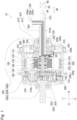
- Fig. 1 is a cross-sectional view illustrating the structure of the motor 10 according to the embodiment of the present invention.
- the motor 10 includes a rotor 100, a stator 200, a hub 300, a circuit board 400, a signal wire 450, a torque sensor 500, a sensor wire 550, a first fixed shaft 610, a second fixed shaft 620, a sun gear 710, a planetary gear 720, and an internal gear 800.
- the rotor 100 is disposed about the rotation axis AX extending in the axial direction AD.
- the rotor 100 rotates about the rotation axis AX.
- the rotor 100 has a substantially columnar shape.
- the rotor 100 rotates about the rotation axis AX with respect to the stator 200.
- the rotor 100 is disposed radially inside the stator 200.
- Such rotor 100 is also called an inner rotor. Since the rotor 100 is positioned radially inside with respect to the stator 200, the rotor 100 becomes smaller in size than a case of being an outer rotor, and the moment of inertia can be reduced, and therefore the responsiveness of force is excellent. Since the rotor 100 rotates stably, power can be efficiently transmitted.
- the stator 200 has a tubular shape.
- the stator 200 surrounds the radial outside of the rotor 100.
- the motor 10 is driven by alternating-current power of three phases (U phase, V phase, and W phase) output from the three output terminals of a control device.
- U phase power, V phase power, and W phase power are input to the stator 200, the rotor 100 rotates with a change in the magnetic field caused in the stator 200.
- the hub 300 has a tubular shape.
- the hub 300 surrounds the radial outside of the stator 200.
- the hub 300 surrounds at least a part of each of the rotor 100 and the stator 200 from axial both sides.
- the hub 300 accommodates the rotor 100, the stator 200, the circuit board 400, the sun gear 710, the planetary gear 720, and the internal gear 800.
- the hub 300 accommodates at least a part of each of the torque sensor 500, the first fixed shaft 610, and the second fixed shaft 620.
- the hub 300 is provided with two openings. One opening of the hub 300 is positioned on an axial one side. The other opening of the hub 300 is positioned on the axial other side.
- the hub 300 rotates with rotation of the rotor 100.
- the rotation speed of the hub 300 is smaller than the rotation speed of the rotor 100.
- the hub 300 includes a housing portion 300h, an opening 300p, and an opening 300q.
- the housing portion 300h is a container having two opposing bottom surfaces and side surfaces.
- the opening 300p and the opening 300q are provided on the bottom surface of the housing portion 300h.
- the opening 300p is positioned on an axial one side of the housing portion 300h.
- the torque sensor 500 and the first fixed shaft 610 penetrate the opening 300p.
- the opening 300q is positioned on the axial other side of the housing portion 300h.
- the second fixed shaft 620 penetrates the opening 300q.
- the hub 300 includes a body portion 310 and a lid portion 320.
- the body portion 310 is a container in which an axial one side is opened.
- the body portion 310 is positioned on the axial other side with respect to the lid portion 320.
- the surface on the axial other side is provided with an opening penetrating in the axial direction AD.
- the opening of the body portion 310 is the opening 300q.
- the lid portion 320 is positioned on an axial one side with respect to the body portion 310.
- the lid portion 320 covers the axial one side of the body portion 310.
- the lid portion 320 is provided with an opening penetrating in the axial direction AD.
- the opening of the lid portion 320 is the opening 300p.
- An outer peripheral surface of the hub 300 is provided with protrusion portions 330a and 330b protruding radially outward.
- the protrusion portion 330a and the protrusion portion 330b extend in the circumferential direction CD on the outer peripheral surface of the hub 300.
- the protrusion portion 330a and the protrusion portion 330b are positioned apart at a predetermined interval.
- the protrusion portion 330a and the protrusion portion 330b are provided on an outer peripheral surface of the body portion 310, and the protrusion portion 330a is positioned on the axial other side relative to the protrusion portion 330b.
- the protrusion portion 330b is positioned at an axial one side end part of the outer peripheral surface of the body portion 310.
- the protrusion portion 330a and the protrusion portion 330b are provided with through holes 330p at equal intervals.
- the through hole 330p is used for fixing a rotation target object to the hub 300.
- the through hole 330p on the outer peripheral surface of the hub 300 is attached with a tip end of a spoke of the wheel of the bicycle.
- the circuit board 400 is accommodated in the hub 300.
- the circuit board 400 has a substantially circular shape.
- the circuit board 400 is substantially orthogonal to the axial direction AD.
- the circuit board 400 faces in the axial direction AD at least a part of the rotor 100 and is disposed substantially horizontally.
- the circuit board 400 needs not have a substantially circular shape.
- the circuit board 400 may have a circular half shape.
- the circuit board 400 is positioned on an axial one side with respect to the rotor 100.
- the circuit board 400 is positioned between the rotor 100 and the torque sensor 500.
- the circuit board 400 includes a printed board on which a wire is printed.
- the circuit board 400 is mounted with various electronic components.
- the signal wire 450 is connected to the circuit board 400.
- the signal wire 450 includes one or more lead wires.
- the signal wire 450 is connected to the circuit board 400 on the surface on the axial one side of the circuit board 400.
- the signal wire 450 transmits a signal acquired or generated in the circuit board 400.
- the torque sensor 500 has a tubular shape.
- the torque sensor 500 is positioned on an axial one side with respect to the rotor 100.
- the torque sensor 500 is attached with the first fixed shaft 610 and the hub 300.
- the first fixed shaft 610 penetrates radial inside of the torque sensor 500.
- the hub 300 is disposed radial outside the torque sensor 500.
- the torque sensor 500 includes an inner component 500s and an outer component 500t.
- the outer component 500t is positioned radially outside with respect to the inner component 500s.
- the inner component 500s faces the first fixed shaft 610.
- the inner component 500s is fixed to the hub 300.
- the inner component 500s rotates together with the hub 300.
- the outer component 500t is attached to a rotation member.
- the outer component 500t rotates together with the rotation member.
- the outer component 500t is fixed to a sprocket 30 ( Fig. 9 and Fig. 10 ) as a rotation member.
- the outer component 500t rotates together with the sprocket 30.
- a part of a radially outer surface of the inner component 500s and a part of a radially inner surface of the outer component 500t are connected via a one-way clutch not illustrated. Due to this, the rotational force of the hub 300 is transmitted to the outer component 500t via the inner component 500s, and the force is transmitted to the sprocket 30 fixed to the outer component 500t.
- the torque sensor 500 detects, by a change in inductance, strain between the hub 300 and the sprocket 30 by the inner component 500s rotating together with the hub 300 and the outer component 500t rotating together with the sprocket 30.
- the motor 10 further includes a bearing 510, a bearing 520, and a bearing 530.
- the bearing 520 is positioned on an axial one side with respect to the bearing 510.
- the bearing 530 is positioned on an axial one side with respect to the bearing 520.
- the bearing 510 is positioned between the torque sensor 500 and the first fixed shaft 610. Specifically, the bearing 510 is positioned between the inner component 500s and the first fixed shaft 610.
- the bearing 510 is, for example, a rolling bearing.
- the bearing 510 is positioned radially inside the inner component 500s and positioned radially outside the first fixed shaft 610.
- the bearing 510 rotatably supports the inner component 500s with respect to the first fixed shaft 610.
- the bearing 520 is positioned between the inner component 500s and the outer component 500t.
- the bearing 520 is, for example, a rolling bearing.
- the bearing 520 is positioned radially inside the outer component 500t and positioned radially outside the inner component 500s.
- the bearing 520 rotatably supports the outer component 500t with respect to the inner component 500s.
- the bearing 530 is positioned between the torque sensor 500 and the first fixed shaft 610. Specifically, the bearing 530 is positioned between the outer component 500t and the first fixed shaft 610.
- the bearing 530 is, for example, a rolling bearing.
- the bearing 530 is positioned radially inside the outer component 500t and positioned radially outside the first fixed shaft 610.
- the bearing 530 rotatably supports the outer component 500t with respect to the first fixed shaft 610.
- the sensor wire 550 electrically connects the torque sensor 500 and the circuit board 400.
- the sensor wire 550 includes one or more lead wires. One end of the sensor wire 550 is connected to the torque sensor 500 in the hub 300. The other end of the sensor wire 550 is connected to the circuit board 400 in the hub 300.
- the first fixed shaft 610 is positioned on an axial one side with respect to the rotor 100.
- the first fixed shaft 610 is attached with the torque sensor 500.
- the first fixed shaft 610 penetrates the torque sensor 500 along the axial direction AD.
- the first fixed shaft 610 extends to an axial one side from the hub 300.
- the first fixed shaft 610 is a stationary member.
- the second fixed shaft 620 is positioned on the axial other side with respect to the rotor 100.
- the second fixed shaft 620 extends to the axial other side from the hub 300.
- the second fixed shaft 620 is a stationary member.
- the rotor 100 includes a rotor core 110 and a magnet 120.
- the magnet 120 is, for example, a permanent magnet.
- the rotor 100 may have a singularity of magnet 120 having a substantially circular shape, or may have a plurality of magnets 120 arrayed in the circumferential direction CD.
- the "substantially circular shape" is, for example, a “substantially annular shape”.
- the number of poles of the magnet 120 is "14".
- the number of poles of the magnet 120 is not limited to this.
- the rotor core 110 has a substantially cylindrical shape.
- the rotor core 110 includes a laminated steel plate in which, for example, electromagnetic steel plates are laminated in the axial direction AD.
- the laminated steel plate is an example of lamination.
- the plurality of magnets 120 are disposed radially outside the rotor core 110.
- the motor 10 is a surface permanent magnet (SPM) motor.
- the rotor 100 may be a spoke type rotor.
- the motor 10 may be an interior permanent magnet (IPM) motor.
- the rotor 100 may further include a magnet covering portion 130.
- the magnet covering portion 130 covers at least a part of each of the rotor core 110 and the magnet 120.
- the magnet covering portion 130 covers a part of the rotor core 110 and the magnet 120 from axial both sides.
- the magnet covering portion 130 covers the rotor core 110 and the magnet 120 from radial outside.
- the magnet covering portion 130 can suppress the magnet 120 from separating from the rotor core 110.
- the rotor 100 further includes a bearing 140.
- the bearing 140 rotatably supports a rotor shaft 160.
- the bearing 140 is, for example, a rolling bearing.
- the bearing 140 is positioned radially inside the rotor core 110 and positioned radially outside the rotor shaft 160.
- the rotor 100 further includes a one-way clutch 150.
- the one-way clutch 150 is positioned radially inside the rotor core 110 and positioned radially outside the rotor shaft 160.
- the rotor 100 further includes the rotor shaft 160.
- the rotor shaft 160 is disposed radially inside the rotor core 110.
- the rotor shaft 160 rotates together with the rotor core 110 and the magnet 120.
- the rotor shaft 160 rotates together with the rotor core 110 and the magnet 120 on a circumferential one side by the one-way clutch 150, but does not rotate together with the rotor core 110 and the magnet 120 on the circumferential other side.
- the stator 200 has a substantially cylindrical shape.
- the stator 200 is disposed about the rotation axis AX extending in the axial direction AD.
- the stator 200 is disposed radially outside the rotor 100.
- the stator 200 faces the magnet 120 in the radial direction RD.
- the stator 200 includes a stator core 210, an insulator 220, and a coil 230.
- the stator core 210 is disposed about the rotation axis AX extending in the axial direction AD.
- the stator core 210 has a substantially circular shape about the rotation axis AX.
- the "substantially circular shape” is, for example, a “substantially annular shape”.
- the stator core 210 includes a laminated steel plate in which, for example, thin electromagnetic steel plates are laminated in the axial direction AD.
- the laminated steel plate is an example of lamination.
- the stator core 210 includes a core back and teeth.
- the insulator 220 covers at least a part of the stator core 210. As an example, the insulator 220 surrounds the stator core 210 from axial both sides.
- the insulator 220 has a substantially circular shape.
- the "substantially circular shape” is, for example, a "substantially annular shape”.
- the insulator 220 is an electrical insulator.
- the insulator 220 electrically insulates the stator core 210 from the coil 230.
- the insulator 220 may include a single member or may include a plurality of separate members.
- the insulator 220 is a resin molded article into which the stator core 210 is inserted.
- the insulator 220 may have a structure to be separately attached to the stator core 210.
- the coil 230 is wound around the stator core 210 via the insulator 220.
- the coil 230 is a coated conductive wire in which a metal wire is covered with a coating film.
- the material of the metal wire is, for example, copper. However, the material of the metal wire may be aluminum in place of copper.
- the coating film covering the metal wire is, for example, an insulating resin.
- the motor 10 further includes a first stator cover 260 and a second stator cover 270.
- the first stator cover 260 is disposed on an axial one side (+X direction) of the stator 200.
- the first stator cover 260 covers at least a part of the stator 200 from an axial one side.
- the second stator cover 270 is disposed on the axial other side (-X direction) of the stator 200.
- the second stator cover 270 covers the stator 200 from the axial other side.
- At least a part of an end part of radially outside of the stator core 210 directly faces the hub 300 without being covered by the first stator cover 260 and the second stator cover 270. This eliminated the need for covering the outside of the stator 200 with a separate member, and therefore can reduce the weight of the motor 10.
- An end part of radially outside of the first stator cover 260 faces the stator 200 in the axial direction AD.
- An end part of radially outside of the second stator cover 270 faces the stator 200 in the axial direction AD.
- the rotor 100 and the stator 200 are disposed in a space formed by the first stator cover 260 and the second stator cover 270.
- the circuit board 400 is disposed in a space formed by the first stator cover 260 and the second stator cover 270.
- the circuit board 400 is fixed to the first stator cover 260.
- An end part of an axial one side of the rotor shaft 160 is positioned in a through hole 260p extending in the axial direction AD at the radial center of the first stator cover 260.
- the rotor shaft 160 penetrates a through hole 270p extending in the axial direction AD at the radial center of the second stator cover 270 on the axial other side.
- the sun gear 710 is positioned at a tip end of the rotor shaft 160.
- the sun gear 710 is positioned at a tip end on the axial other side with respect to the rotor shaft 160.
- the sun gear 710 rotates together with the rotor shaft 160.
- the planetary gear 720 is positioned radially outside the sun gear 710.
- the planetary gear 720 meshes with the sun gear 710.
- the planetary gear 720 rotates in conjunction with the sun gear 710.
- the planetary gear 720 is supported by the second stator cover 270.
- the sensor wire 550 electrically connects the torque sensor 500 and the circuit board 400. Through the sensor wire 550, a signal detected by the torque sensor 500 is transmitted to the circuit board 400.
- the signal wire 450 is connected to the circuit board 400.
- the signal wire 450 transmits a signal acquired in the circuit board 400.
- the signal wire 450 transmits, from the circuit board 400 to an external circuit, a signal detected in the circuit board 400.
- the signal wire 450 transmits, from the circuit board 400 to an external circuit, a signal detected by the torque sensor 500 and transmitted to the circuit board 400.
- the motor 10 further includes a control wire 250.
- the control wire 250 electrically connects the stator 200 and the control device.
- the control wire 250 includes one or more lead wires.
- the rotor 100 rotates with respect to the stator 200 by a control signal transmitted through the control wire 250.
- the motor 10 is driven by alternating-current power of three phases output from the three output terminals of the control device.
- the motor 10 is driven by the U phase power, the V phase power, and the W phase power.
- the control device changes the control current to be supplied to the stator 200 based on a detection result of the torque sensor 500. This can control rotation of the rotor 100.
- control wire 250 Through the control wire 250, control signals of three phases (U phase, V phase, and W phase) output from the three output terminals of the control device are transmitted.
- the control wire 250 has three or more lead wires.
- the control wire 250 transmits power of the U phase, the V phase, and the W phase.
- the control wire 250 includes a wire 250u that transmits the U phase power, a wire 250v that transmits the V phase power, and a wire 250w that transmits the W phase power.
- the first fixed shaft 610 includes a tube portion 612 and a base portion 614.
- the tube portion 612 has a tubular shape extending in the axial direction AD.
- the base portion 614 has a plate shape extending radially outward from the radial center.
- the tube portion 612 extends to an axial one side from the base portion 614.
- the length along the axial direction AD of the base portion 614 is smaller than the length along the axial direction AD of the tube portion 612.
- An outer diameter along the radial direction RD of the base portion 614 is larger than an outer diameter along the radial direction RD of the tube portion 612.
- the tube portion 612 is provided with a through hole 612p extending in the axial direction AD.
- the signal wire 450 penetrates the tube portion 612 in the axial direction AD.
- the control wire 250 penetrates the tube portion 612 in the axial direction AD. This reduces a part where the signal wire 450 is exposed to the outside, and therefore can suppress damage or the like of the signal wire 450.
- the second fixed shaft 620 includes a projection portion 622 and a base portion 624.
- the projection portion 622 has a rod shape extending in the axial direction AD.
- the base portion 624 has a plate shape extending radially outward from the radial center.
- the projection portion 622 extends to the axial other side from the base portion 624.
- the length along the axial direction AD of the base portion 624 is smaller than the length along the axial direction AD of the projection portion 622.
- An outer diameter along the radial direction RD of the base portion 624 is larger than an outer diameter along the radial direction RD of the projection portion 622.
- the motor 10 further includes the internal gear 800.
- the internal gear 800 is accommodated in the hub 300.
- the internal gear 800 is fixed to an inner peripheral surface of the hub 300.
- the internal gear 800 is attached to the body portion 310 of the hub 300.
- the internal gear 800 has a circular shape.
- the internal gear 800 has a flat outer peripheral surface and an inner peripheral surface provided with a gear.
- the internal gear 800 is positioned radially outside the planetary gear 720.
- the internal gear 800 meshes with the planetary gear 720.
- the internal gear 800 rotates together with the planetary gear 720.
- Fig. 2 is a perspective view of the motor 10 according to the embodiment of the present invention.
- the hub 300, the first fixed shaft 610, and the second fixed shaft 620 are exposed to the outside.
- the first fixed shaft 610 extends from the hub 300 in an axial one side (+X direction) along the rotation axis AX.
- the second fixed shaft 620 extends from the hub 300 in the axial other side (-X direction) along the rotation axis AX.
- the first fixed shaft 610 and the second fixed shaft 620 extend linearly along the rotation axis AX from the hub 300.
- the length of the first fixed shaft 610 is different from the length of the second fixed shaft 620.
- the length of the first fixed shaft 610 is larger than the length of the second fixed shaft 620. This can easily attach the torque sensor 500 to the first fixed shaft 610.
- the length of the second fixed shaft 620 may be larger than the length of the first fixed shaft 610.
- the hub 300 includes the body portion 310 and the lid portion 320.
- the body portion 310 is a container in which an axial one side is opened. In the body portion 310, the surface on the axial other side is provided with an opening at the center.
- the lid portion 320 is positioned on an axial one side with respect to the body portion 310. The lid portion 320 covers an opening positioned on an axial one side of the body portion 310.
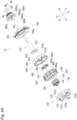
- Fig. 3 is an exploded perspective view of the motor 10 according to the embodiment of the present invention.
- Figs. 4A and 4B are partially enlarged views of Fig. 3 .
- Fig. 4A illustrates the configuration on an axial one side of the motor 10
- Fig. 4B illustrates the configuration on the axial other side of the motor 10.
- the torque sensor wire, the signal wire, and the control wire are omitted in order to avoid the drawing from being excessively complicated.
- the motor 10 includes the rotor 100, the stator 200, the first stator cover 260, the second stator cover 270, the hub 300, the circuit board 400, the torque sensor 500, the first fixed shaft 610, the second fixed shaft 620, the sun gear 710, the planetary gear 720, and the internal gear 800.
- the hub 300 includes the body portion 310 and the lid portion 320.
- the rotor 100 includes the rotor core 110, the magnet 120, the magnet covering portion 130, and the rotor shaft 160.
- the torque sensor 500 is positioned on an axial one side with respect to the lid portion 320.
- the torque sensor 500 is positioned on an axial one side with respect to the circuit board 400.
- the torque sensor 500 is fixed to the lid portion 320 at a position apart by a predetermined distance from the circuit board 400.
- the torque sensor 500 has a substantially cylindrical shape.
- the torque sensor 500 has an outer peripheral surface 500a and an inner peripheral surface 500b.
- the outer peripheral surface 500a includes a first portion 500a1, a second portion 500a2, and a third portion 500a3.
- the first portion 500a1, the second portion 500a2, and the third portion 500a3 are positioned in order from the axial other side to the axial one side.
- the outer diameter of the second portion 500a2 is larger than the outer diameter of the first portion 500a1.
- the outer diameter of the second portion 500a2 is larger than the outer diameter of the third portion 500a3.
- the second portion 500a2 is provided with a through hole 500q extending in the axial direction AD. With a fixing tool penetrating the through hole 500q of the second portion 500a2, the torque sensor 500 can be fixed to the lid portion 320.
- the outer diameter of the outer peripheral surface 500a changes along the axial direction AD.
- the inner diameter of the inner peripheral surface 500b is substantially constant along the axial direction AD.
- the lid portion 320 is positioned between the torque sensor 500 and the first stator cover 260 in the axial direction AD.
- the lid portion 320 includes a plate portion 322 provided with a through hole at the center and a side portion 324 extending from an outer edge of the plate portion 322 to the axial other side.
- the through hole of the plate portion 322 is the opening 300p.
- the torque sensor 500 penetrates the opening 300p.
- the torque sensor 500 is attached to the first fixed shaft 610.
- the first fixed shaft 610 penetrates the torque sensor 500. Therefore, the first fixed shaft 610 penetrates the opening 300p of the lid portion 320.
- the first fixed shaft 610 includes a tube portion 612 and a base portion 614.
- the tube portion 612 has a tubular shape extending in the axial direction AD.
- the tube portion 612 extends to an axial one side from the base portion 614.
- the tube portion 612 is provided with the through hole 612p extending in the axial direction AD.
- the base portion 614 has a plate shape extending radially outward from the radial center.
- the outer diameter along the radial direction RD of the base portion 614 is larger than the outer diameter along the radial direction RD of the tube portion 612.
- the base portion 614 is attached to the first stator cover 260 with a screw.
- the base portion 614 may be attached to the first stator cover 260 with an adhesive.
- the base portion 614 may be a single member with first stator cover 260.
- the base portion 614 is provided with a cutout 614n in which a part of a disk shape is cut out.
- the cutout 614n is continuous with the through hole 612p.
- the control wire 250 and the signal wire 450 (see Fig. 1 ) are arranged in the cutout 614n. This can easily arrange the control wire 250 and the signal wire 450.
- the cutout 614n is cut out at an angle of 90° or less among the angle of 360° in the circumferential direction CD about the rotation axis AX. This can stably attach the base portion 614 to the first stator cover 260.
- the first stator cover 260 is positioned on the axial other side of the lid portion 320.
- An outer diameter along the radial direction RD of the first stator cover 260 is smaller than an inner diameter along the radial direction RD of the lid portion 320.
- the outer diameter along the radial direction RD of the first stator cover 260 is smaller than an inner diameter along the radial direction RD of the body portion 310. Therefore, the first stator cover 260 is accommodated in the hub 300 in which the body portion 310 and the lid portion 320 are combined.
- the first stator cover 260 is positioned on the axial other side of the first fixed shaft 610.
- An outer diameter along the radial direction RD of the first stator cover 260 is larger than an outer diameter along the radial direction RD of the base portion 614.
- the first fixed shaft 610 is fixed to a surface on an axial one side of the first stator cover 260.
- the first stator cover 260 covers the stator 200 from an axial one side.
- the first stator cover 260 includes a plate-shaped portion 262 and a side surface portion 264.
- the plate-shaped portion 262 has a disk shape provided with the through hole 260p at the center.
- the side surface portion 264 extends to the axial other side from the outer edge of the plate-shaped portion 262.
- the plate-shaped portion 262 is provided with the through hole 260p extending in the axial direction AD. An end part of an axial one side of the rotor 100 is inserted into the through hole 260p.
- the plate-shaped portion 262 is provided with a through hole 260q extending in the axial direction AD separately from the through hole 260p.
- the through hole 260q is not continuous with the through hole 260p.
- the control wire 250, the sensor wire 550, and the signal wire 450 penetrate the through hole 260q. This can easily arrange the control wire 250, the sensor wire 550, and the signal wire 450 (see Fig. 1 ).
- the circuit board 400 is positioned on the axial other side with respect to the first stator cover 260.
- the circuit board 400 has a substantially circular shape.
- the circuit board 400 includes a printed board 402 having a substantially circular shape and a detection element 404 mounted on the printed board 402.
- the circuit board 400 is positioned between the rotor 100 and the first stator cover 260.
- the detection element 404 includes a Hall element.
- the Hall element detects rotation of the rotor 100 by detecting the magnetic field of the rotor 100.
- the detection element 404 may include a temperature detection element.
- the temperature detection element detects a temperature in the hub 300.
- the stator 200 is positioned on the axial other side with respect to the first stator cover 260.
- the stator 200 has a substantially cylindrical shape.
- the stator 200 is disposed about the rotation axis AX extending in the axial direction AD.
- the stator 200 is disposed radially outside the rotor 100.
- the stator 200 is positioned on an axial one side of the second stator cover 270.
- the stator 200 includes a stator core 210, an insulator 220, and a coil 230.
- the stator core 210 is disposed about the rotation axis AX extending in the axial direction AD.
- the insulator 220 covers at least a part of the stator core 210. As an example, the insulator 220 surrounds the stator core 210 from axial both sides.
- the coil 230 is wound around the stator core 210 via the insulator 220.
- the rotor 100 is positioned on the axial other side with respect to the circuit board 400.
- the rotor 100 is disposed about the rotation axis AX extending in the axial direction AD.
- the rotor 100 rotates about the rotation axis AX.
- the rotor 100 is disposed radially inside the stator 200.
- the rotor 100 includes the rotor core 110, the magnet 120, the magnet covering portion 130, and the rotor shaft 160.
- the rotor core 110 has a substantially cylindrical shape.
- the rotor core 110 includes a laminated steel plate in which, for example, electromagnetic steel plates are laminated in the axial direction AD.
- the magnet 120 is disposed radially outside the rotor core 110.
- the magnet covering portion 130 covers at least a part of each of the rotor core 110 and the magnet 120.
- the magnet covering portion 130 covers a part of the rotor core 110 and the magnet 120 from axial both sides.
- the magnet covering portion 130 covers the rotor core 110 and the magnet 120 from radial outside.
- the rotor shaft 160 is positioned radially inside the rotor core 110.
- the rotor shaft 160 rotates together with the rotor core 110 and the magnet 120.
- the second stator cover 270 is positioned on the axial other side of the rotor 100.
- An outer diameter along the radial direction RD of the second stator cover 270 is smaller than the inner diameter along the radial direction RD of the body portion 310. Therefore, the second stator cover 270 is accommodated in the hub 300 in which the body portion 310 and the lid portion 320 are combined.
- the second stator cover 270 is positioned on the axial other side of the rotor 100 and the stator 200.
- the second stator cover 270 covers the stator 200 from the axial other side.
- the second stator cover 270 includes a plate-shaped portion 272 and a side surface portion 274.
- the plate-shaped portion 272 has a disk shape provided with the through hole 270p at the center.
- the side surface portion 274 extends to an axial one side from the outer edge of the plate-shaped portion 272.
- the plate-shaped portion 272 is provided with the through hole 270p extending in the axial direction AD. An end part of the axial other side of the rotor 100 penetrates the through hole 270p.
- the surface on the axial other side of the plate-shaped portion 272 is provided with projection portions 272a, 272b, and 272c projecting to the axial other side.
- the projection portions 272a, 272b, and 272c are attached with a gear shaft not illustrated, and the planetary gear 720 is attached to the gear shaft.
- the rotor shaft 160 penetrates the second stator cover 270.
- the tip end on the axial other side of the rotor shaft 160 penetrates the through hole 270p.
- the sun gear 710 is positioned at the tip end on the axial other side of the rotor shaft 160.
- the sun gear 710 is positioned on the axial other side with respect to the second stator cover 270.
- the sun gear 710 rotates together with the rotor shaft 160.
- the planetary gear 720 is positioned on the axial other side with respect to the second stator cover 270.
- the planetary gear 720 is positioned radially outside the sun gear 710.
- the planetary gear 720 meshes with the sun gear 710 and rotates with rotation of the rotor 100.
- the planetary gear 720 includes a first planetary gear 720a, a second planetary gear 720b, and a third planetary gear 720c arranged at equal intervals about the rotation axis AX.
- the first planetary gear 720a, the second planetary gear 720b, and the third planetary gear 720c are attached to the projection portions 272a, 272b, and 272c of the plate-shaped portion 272.
- the first planetary gear 720a, the second planetary gear 720b, and the third planetary gear 720c mesh with the sun gear 710 and rotate with rotation of the rotor 100.
- the internal gear 800 is positioned on the axial other side with respect to the second stator cover 270.
- the internal gear 800 is positioned radially outside with respect to the planetary gear 720.
- the internal gear 800 has a cylindrical shape.
- the inner peripheral surface of the internal gear 800 is provided with teeth.
- the internal gear 800 is positioned at an end part of the axial other side of the body portion 310.
- the internal gear 800 is attached to the body portion 310.
- the internal gear 800 meshes with the planetary gear 720.
- the internal gear 800 meshes with the planetary gears 720 and rotates with the rotation of the rotor 100.
- the second fixed shaft 620 is positioned on the axial other side with respect to the second stator cover 270.
- the second fixed shaft 620 is attached to the second stator cover 270 with a screw.
- the second fixed shaft 620 may be attached to the second stator cover 270 with an adhesive.
- the second fixed shaft 620 may include a single member with the second stator cover 270.
- the second fixed shaft 620 includes a projection portion 622 and a base portion 624.
- the projection portion 622 has a tubular shape extending in the axial direction AD.
- the projection portion 622 extends to the axial other side from the base portion 624.
- the base portion 624 has a plate shape extending radially outward from the radial center.
- the length along the axial direction AD of the base portion 624 is smaller than the length along the axial direction AD of the projection portion 622.
- the outer diameter along the radial direction RD of the base portion 624 is larger than the outer diameter along the radial direction RD of the projection portion 622.
- the second fixed shaft 620 penetrates the body portion 310.
- the second fixed shaft 620 penetrates the opening 300q of the body portion 310.
- the body portion 310 is positioned on the axial other side with respect to the lid portion 320.
- the body portion 310 includes a bottom portion 312 provided with a through hole at the center and a side portion 314 extending from an outer edge of the bottom portion 312 to an axial one side.
- the through hole of the bottom portion 312 is the opening 300q.
- the motor 10 includes the rotor 100, the stator 200, the hub 300, the circuit board 400, the signal wire 450, the torque sensor 500, the sensor wire 550, and the first fixed shaft 610.
- the rotor 100 has the rotor shaft 160 extending along a virtual central axis. The rotor 100 rotates about the rotor shaft 160.
- the stator 200 is positioned radially outside with respect to the rotor 100.
- the hub 300 accommodates the rotor 100 and the stator 200.
- the hub 300 rotates with rotation of the rotor 100.
- the torque sensor 500 is positioned on an axial one side with respect to the rotor 100.
- the circuit board 400 is accommodated in the hub 300.
- the circuit board 400 is positioned between the rotor 100 and the torque sensor 500.
- the sensor wire 550 electrically connects the torque sensor 500 and the circuit board 400.
- the signal wire 450 is electrically connected to an external circuit on the surface on an axial one side of the circuit board 400.
- the first fixed shaft 610 is a stationary member.
- the first fixed shaft 610 is positioned on an axial one side with respect to the rotor shaft 160.
- the first fixed shaft 610 supports the torque sensor 500.
- the circuit board 400 is positioned between the rotor 100 and the torque sensor 500 positioned on an axial one side with respect to the rotor 100, the sensor wire 550 and the signal wire 450 can be collectively arranged on one side with respect to the rotor 100, and therefore the sensor wire 550 and the signal wire 450 can be suppressed from coming into contact with the rotor 100.
- the sensor wire 550 and the signal wire 450 can be easily attached to the circuit board 400, and a signal detected by the torque sensor 500 can be easily output to the outside.
- the rotor 100 is an inner rotor, high output can be obtained with low vibration even if the motor 10 is small.
- the motor 10 further includes the first stator cover 260 that covers an axial one side of the stator 200 and the second stator cover 270 that covers the axial other side of the stator 200.
- the circuit board 400 is positioned between the rotor 100 and the first stator cover 260.
- the first stator cover 260 is provided with the through hole 260q through which the sensor wire 550 and the signal wire 450 penetrate in the axial direction AD. This can easily attach the sensor wire 550 and the signal wire 450 to the circuit board 400.
- At least a part of the first fixed shaft 610 extends to an axial one side from the hub 300.
- the first fixed shaft 610 is attached with the torque sensor 500.
- the first fixed shaft 610 includes the tube portion 612 in which the signal wire 450 is internally disposed. Due to this, since the signal wire 450 is arranged inside the tube portion 612 of the first fixed shaft 610 attached with the torque sensor 500, the signal wire 450 can be suppressed from being exposed to the outside.
- the first fixed shaft 610 further includes the base portion 614 coupled to the tube portion 612.
- the base portion 614 is attached to the first stator cover 260.
- the base portion 614 is provided with the cutout 614n continuous with the through hole 612p of the tube portion 612. This can easily attach the sensor wire 550 and the signal wire 450 to the circuit board 400.
- the motor 10 further includes the second fixed shaft 620 positioned on the axial other side with respect to the rotor shaft 160. At least a part of the second fixed shaft 620 extends to the axial other side from the hub 300. This can arrange the first fixed shaft 610 and the second fixed shaft 620 symmetrically with respect to the hub 300.
- the motor 10 further includes the control wire 250 through which the stator 200 is supplied with a control current.
- the first fixed shaft 610 includes the tube portion 612 in which the control wire 250 is internally disposed. This can change the control current supplied to the stator 200 based on a detection result of the torque sensor 500, and can control rotation of the rotor 100. Since the control wire 250 is disposed inside the tube portion 612 of the first fixed shaft 610, the control wire 250 can be suppressed from being exposed to the outside.
- the motor 10 further includes the sun gear 710 and the planetary gear 720.
- the sun gear 710 is attached to the axial other side with respect to the rotor shaft 160.
- the planetary gear 720 further includes the planetary gear 720 that meshes with the sun gear 710 and is disposed on the axial other side with respect to the rotor 100. This can suppress the sensor wire 550 and the signal wire 450 from coming into contact with the sun gear 710 and the planetary gear 720.
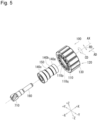
- Fig. 5 is an exploded perspective view of the rotor 100 in the motor 10 according to the embodiment of the present invention.
- an end part of the axial other side of the rotor shaft 160 is attached with the sun gear 710.
- the rotor 100 includes the rotor core 110, the magnet 120, the magnet covering portion 130, the bearing 140, the one-way clutch 150, and the rotor shaft 160.
- the rotor core 110 has a cylindrical shape.
- the rotor core 110 is provided with a through hole 110p extending in the axial direction AD at the radial center.
- the rotor core 110 is provided with a plurality of through holes 110q extending in the axial direction AD radially outside the through hole 110p.
- the plurality of through holes 110q are arranged at equal intervals along the circumferential direction CD.
- the number of the plurality of through holes 110q is 14.
- the rotor shaft 160 is positioned radially inside the rotor core 110.
- the bearing 140 rotatably supports a rotor shaft 160.
- the bearing 140 is, for example, a rolling bearing.
- the bearing 140 is positioned radially inside the rotor core 110 and positioned radially outside the rotor shaft 160.
- the bearing 140 includes a bearing 140a, a bearing 140b, and a bearing 140c.
- the bearing 140a, the bearing 140b, and the bearing 140c are arranged in order from an axial one side to the axial other side.
- the one-way clutch 150 is positioned radially inside the rotor core 110 and positioned radially outside the rotor shaft 160.
- the one-way clutch 150 is positioned between the bearing 140b and the bearing 140c in the axial direction AD.
- the one-way clutch 150 transmits, to the rotor shaft 160, rotation of only a circumferential one side of the rotor core 110 and the magnet 120. Specifically, the one-way clutch 150 transmits, to the rotor shaft 160, rotation to a circumferential one side of the rotor core 110 and the magnet 120, and does not transmit, to the rotor shaft 160, rotation to the circumferential other side of the rotor core 110 and the magnet 120.
- the motor 10 further includes the one-way clutch 150 attached to the rotor shaft 160. This can reduce the size of the one-way clutch 150, and therefore can reduce the size and weight of the motor 10.
- control wire 250, the signal wire 450, and the sensor wire 550 are arranged on the axial one side with respect to the rotor 100.
- Fig. 6 is an exploded perspective view of the torque sensor 500, the first fixed shaft 610, the rotor 100, the stator 200, the first stator cover 260, the body portion 310, and the circuit board 400 in the motor 10 according to the embodiment of the present invention.
- the lid portion 320 of the hub 300 is omitted in order to avoid the drawing from being excessively complicated.
- the first fixed shaft 610 penetrates the torque sensor 500.
- the tube portion 612 of the first fixed shaft 610 penetrates the through hole of the torque sensor 500.
- the body portion 310 of the hub 300 accommodates the rotor 100, the stator 200, the first stator cover 260, and the circuit board 400.
- the first stator cover 260 is positioned on an axial one side with respect to the rotor 100 and the stator 200.
- the plate-shaped portion 262 is positioned on an axial one side.
- the surface on an axial one side of the plate-shaped portion 262 is provided with a recess 260r and the through hole 260q.
- An outer edge of the recess 260r has a substantially circular shape in which a part is cut out.
- the plate-shaped portion 262 is provided with the through hole 260q penetrating in the axial direction AD.
- the plate-shaped portion 262 of the first stator cover 260 is provided with the recess 260r extending in the axial direction AD.
- the torque sensor 500 is fitted into the recess 260r.
- An inner diameter along the radial direction RD of the recess 260r is substantially equal to an outer diameter along the radial direction RD of the first portion 500a1 ( Fig. 4A ) of the torque sensor 500.
- the circuit board 400 faces the coil 230 of the stator 200 in the radial direction RD. This can shorten the length in the axial direction AD of the motor 10, and thus can downsize the motor 10.
- the circuit board 400 is disposed radially inside relative to the coil 230. However, the circuit board 400 may be disposed at a position overlapping the coil 230 in the axial direction AD.
- the stator 200 and the circuit board 400 are positioned on the axial other side with respect to the plate-shaped portion 262 of the first stator cover 260, and parts of the stator 200 and the circuit board 400 are exposed by the through hole 260q.
- the inner diameter along the radial direction RD of the recess 260r is substantially equal to an outer diameter along the radial direction RD of the circuit board 400.
- the first stator cover 260 is provided with the through hole 260p extending in the axial direction AD at the radial center. The end part of an axial one side of the rotor shaft 160 is exposed by the through hole 260p.
- control wire 250, the signal wire 450, and the sensor wire 550 extend to an axial one side from the surface on the axial one side with respect to the rotor 100 in the body portion 310.
- the control wire 250 is connected to the stator 200.
- the control wire 250 is connected to one end of the coil 230 of the stator 200.
- the control wire 250 includes the wires 250u, 250v, and 250w for supplying the control currents of the U phase, the V phase, and the W phase.
- the control wire 250 passes through the through hole 612p of the tube portion 612 via the cutout 614n ( Figs. 3 and 4A ) of the first fixed shaft 610 from the stator 200 exposed by the through hole 260q of the first stator cover 260.
- the signal wire 450 electrically connects the circuit board 400 and the external circuit.
- the signal wire 450 electrically connects the surface on the axial one side of the circuit board 400 and the external circuit.
- the signal wire 450 passes through the through hole 612p of the tube portion 612 via the cutout 614n ( Figs. 3 and 4A ) of the first fixed shaft 610 from the circuit board 400 exposed by the through hole 260q of the first stator cover 260.
- the sensor wire 550 electrically connects the torque sensor 500 and the circuit board 400. One end of the sensor wire 550 is connected to the torque sensor 500 in the hub 300. The other end of the sensor wire 550 is connected to the circuit board 400 in the hub 300.
- the sensor wire 550 connects the circuit board 400 exposed by the through hole 260q of the first stator cover 260 and the torque sensor 500.
- the sensor wire 550 has one or more lead wires, but the present embodiment is not limited to this.
- the sensor wire 550 may include a connector in addition to the one or more lead wires.
- Fig. 7 is an exploded perspective view of the torque sensor 500, the first fixed shaft 610, the rotor 100, the stator 200, the first stator cover 260, the body portion 310, and the circuit board 400 in the motor 10 according to the embodiment of the present invention.
- the exploded perspective view of Fig. 7 has the same configuration as that of the exploded perspective view of Fig. 6 except that the sensor wire 550 connecting the torque sensor 500 and the circuit board 400 has a connector, and redundant description is omitted in order to avoid redundancy.
- the first fixed shaft 610 penetrates the torque sensor 500.
- the tube portion 612 of the first fixed shaft 610 penetrates the through hole of the torque sensor 500.
- the sensor wire 550 electrically connects the torque sensor 500 and the circuit board 400. One end of the sensor wire 550 is connected to the torque sensor 500 in the hub 300. The other end of the sensor wire 550 is connected to the circuit board 400 in the hub 300.
- the sensor wire 550 includes a sensor connection line 552, a first connector 554, a board connection line 556, and a second connector 558.
- the sensor connection line 552 is connected to the torque sensor 500.
- the sensor connection line 552 extends from the axial other side of the outer peripheral surface of the torque sensor 500.
- the first connector 554 is connected to the sensor connection line 552.
- the first connector 554 is attached to an end part of the sensor connection line 552.
- the board connection line 556 is connected to the circuit board 400.
- the board connection line 556 is connected to the surface on an axial one side of the circuit board 400.
- the second connector 558 is connected to the board connection line 556.
- the second connector 558 is attached to an end part of the board connection line 556.
- the second connector 558 can be connected to the first connector 554. By fitting the first connector 554 into the second connector 558, it is possible to connect the second connector 558 to the first connector 554. This can easily connect the first connector 554 to the second connector 558.
- an insertion port of the second connector 558 may face radially outward. This can more easily connect the first connector 554 to the second connector 558.
- the sensor wire 550 includes a sensor connection line 552 connected to the torque sensor 500, a first connector 554 positioned at a tip end of the sensor connection line 552, a board connection line 556 connected to the circuit board 400, and a second connector 558 positioned at a tip end of the board connection line 556 and connected to the first connector 554.
- stator core 210 is covered with the insulating insulator 220 while the coil 230 is exposed, but the present embodiment is not limited to this.
- the coil 230 may be covered with an insulating member.
- Fig. 8 is a schematic perspective view of the stator 200, the second stator cover 270, and the circuit board 400 in the motor 10 according to the embodiment of the present invention.
- the stator 200 includes the stator core 210, the insulator 220, and the coil 230.
- the stator core 210 is disposed about the rotation axis AX extending in the axial direction AD.
- the stator core 210 includes a core back 212 and teeth 214.
- the insulator 220 covers at least a part of the stator core 210.
- the insulator 220 covers the stator core 210 from axial both sides.
- the stator 200 further includes a covering portion 240.
- the covering portion 240 covers the coil 230.
- the covering portion 240 covers the coil 230 from axial both sides.
- the covering portion 240 may cover the coil 230 from radial both sides.
- the covering portion 240 includes an insulating resin.
- the wires 250u, 250v, and 250w are connected to the coil 230.
- the coil 230 being covered with the covering portion 240, it is possible to suppress shaking of the coil 230 when the rotor 100 rotates. Since a winding wire of the coil 230 can be fixed by covering the coil 230 with the covering portion 240, it becomes less likely to receive vibration of the motor 10, and generation of vibration and sound can be suppressed.
- the stator 200 includes the stator core 210, the insulator 220, the coil 230, and the covering portion 240 covering the coil 230.
- the insulator 220 covers the stator core 210.
- the coil 230 is wound around the insulator 220.
- the covering portion 240 covers the coil 230. This can suppress vibration of the motor 10.
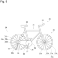
- Fig. 9 is a schematic view of the electric bicycle 20 including the motor 10 according to the embodiment of the present invention.
- Fig. 10 is a schematic perspective view illustrating a part of the electric bicycle 20 including the motor 10 according to the embodiment of the present invention.
- the motor 10 is mounted on the electric bicycle 20.
- the motor 10 assists driving of the electric bicycle 20.
- the motor 10 detects torque of the rear wheel caused by the user rotating the saddle, and assists the rotation of the rear wheel in accordance with the detected torque.
- the motor 10 is mounted on the electric bicycle 20.
- the electric bicycle 20 includes a frame 21, a handlebar 22, the front wheel 23, the rear wheel 24, a saddle 25, a crank 26, a pedal 27, a chain 28, a sprocket 29, the sprocket 30, and a stand 31.
- the motor 10 is attached to the rear wheel 24.
- the handlebar 22 is coupled forward and upward with respect to the frame 21.
- the orientation of the front wheel 23 with respect to the frame 21 can be manipulated with the handlebar 22.
- a hand of the driver of the electric bicycle 20 is placed on the handlebar 22.
- the front wheel 23 is rotatably supported forward and downward of the frame 21.
- the front wheel 23 rotates in contact with the ground.
- the rear wheel 24 is rotatably supported rearward and downward of the frame 21.
- the rear wheel 24 rotates in contact with the ground.
- the saddle 25 is coupled to the upper center with respect to the frame 21.
- the driver of the electric bicycle 20 sits on the saddle 25.
- the crank 26 converts a pedaling force of the driver of the electric bicycle applied to the pedal 27 into a force for driving the rear wheel 24.
- the pedal 27 is disposed at one end of the crank 26. A foot of the driver of the electric bicycle 20 is placed on the pedal 27.
- the sprocket 29 With rotation of the crank 26, the sprocket 29 rotates.
- the chain 28 hangs between the sprocket 29 and the sprocket 30. Therefore, the sprocket 29 is coupled to the sprocket 30 via the chain 28.
- the stand 31 is rotatably attached to a fixed shaft of the frame 21.
- stand 31 is rotated and held in a direction away from the ground.
- the stand 31 is held in a state of rotating in a direction approaching the ground and being in contact with the ground.
- the front wheel 23 includes a wheel 23a and a tire 23b.
- the tire 23b is attached to the wheel 23a.
- the wheel 23a has a rim 23r having a circular shape, a hub 23h positioned at the center of the rim 23r, and a spoke 23s having a rod shape extending from the rim 23r to the hub 23h.
- the rear wheel 24 includes a wheel 24a and a tire 24b.
- the tire 24b is attached to the wheel 24a.
- the wheel 24a has a rim 24r having a circular shape, a hub 300 positioned at the center of the rim 24r, and a spoke 24s having a rod shape extending from the rim 24r to the hub 300.
- the hub 300 of the motor 10 described above is used as the hub of the rear wheel 24.
- the motor 10 is attached to the rear wheel 24. Specifically, the motor 10 is attached to the hub of the rear wheel 24. The rear wheel 24 rotates with rotation of the motor 10. Therefore, the motor 10 assists driving of the electric bicycle 20.
- the motor 10 is attached with the sprocket 30.
- the sprocket 30 is disposed on a side of the torque sensor 500 ( Fig. 1 ).
- the first fixed shaft 610 of the motor 10 penetrates the sprocket 30.
- the sprocket 30 rotates with rotation of the motor 10.
- the electric bicycle 20 includes the motor 10 described above, the front wheel 23, and the rear wheel 24 that rotates with rotation of the motor 10. Therefore, driving of the electric bicycle 20 can be assisted by the motor 10 including the torque sensor 500 together with the rotor 100 and the stator 200.
- the motor 10 is attached to the hub of the rear wheel 24. This can easily mount the motor 10 on the electric bicycle 20.
- the electric bicycle 20 includes the motor 10 described above, the front wheel 23, the rear wheel 24 that rotates with rotation of the motor 10, and the sprocket 30 attached to the rear wheel 24.
- the sprocket 30 faces the first fixed shaft 610. This can suppress the signal wire 450 from coming into contact with the sprocket 30.
- the present technology can have the following configurations.
Landscapes
- Engineering & Computer Science (AREA)
- Mechanical Engineering (AREA)
- Power Engineering (AREA)
- Chemical & Material Sciences (AREA)
- Combustion & Propulsion (AREA)
- Transportation (AREA)
- Microelectronics & Electronic Packaging (AREA)
Abstract
Description
- The present invention relates to a motor and an electric bicycle.
- In recent years, pedelecs have been rapidly spreading. The pedelec can reduce the driver's pedaling force by using the power of an electric motor as auxiliary power (see, for example, Patent Literature 1).
- Patent Literature 1 describes a freehub torque speed sensing device that can accumulate a torque sensor in a freehub of an electric bicycle or a bicycle. In the freehub torque speed sensing device of Patent Literature 1, a freehub body is provided with a torque sensing deformation unit, whereby the completed vehicle can be more conveniently assembled.
- Patent Literature 1:
JP 2022-517380 A - In the freehub torque speed sensing device described in Patent Literature 1, a lead wire extends from an axis opposite to a torque sensor and a sprocket. For this reason, the lead wire extending from the torque sensor to the outside may become long.
- The present invention has been made in view of the above problems, and an object of the present invention is to provide a motor and an electric bicycle that can simplify routing of a lead wire.
- An exemplary motor according to the present invention includes: a rotor having a rotor shaft extending along a virtual central axis, the rotor rotating about the rotor shaft; a stator positioned radially outside with respect to the rotor; a hub that accommodates the rotor and the stator and rotates with rotation of the rotor; a torque sensor positioned on an axial one side with respect to the rotor; a circuit board accommodated in the hub and positioned between the rotor and the torque sensor; a sensor wire electrically connecting the torque sensor and the circuit board; a signal wire electrically connected to an external circuit on a surface on an axial one side of the circuit board; and a first fixed shaft that is a stationary member and is positioned on an axial one side with respect to the rotor shaft. The first fixed shaft supports the torque sensor.
- An exemplary electric bicycle according to the present invention includes: the motor described above; a front wheel; and a rear wheel that rotates with rotation of the motor.
- An exemplary electric bicycle according to the present invention includes: the motor described above; a front wheel; a rear wheel that rotates with rotation of the motor; and a sprocket attached to the rear wheel, wherein the sprocket faces the first fixed shaft.
- According to the exemplary present invention, it is possible to provide a motor in which a torque sensor is integrated with a rotor and a stator.
-
-
Fig. 1 is a cross-sectional view illustrating a structure of a motor according to an embodiment of the present invention. -
Fig. 2 is a perspective view of the motor according to the embodiment of the present invention. -
Fig. 3 is an exploded perspective view of the motor according to the embodiment of the present invention. -
Fig. 4A is a partially enlarged view ofFig. 3 . -
Fig. 4B is a partially enlarged view ofFig. 3 . -
Fig. 5 is a perspective view of a rotor in the motor according to the embodiment of the present invention. -
Fig. 6 is an exploded perspective view of a torque sensor, a first fixed shaft, the rotor, the stator, a first stator cover, a body portion, and a circuit board in the motor according to the embodiment of the present invention. -
Fig. 7 is an exploded perspective view of the torque sensor, the first fixed shaft, the rotor, the stator, the first stator cover, the body portion, and the circuit board in the motor according to the embodiment of the present invention. -
Fig. 8 is a schematic perspective view of the stator in the motor according to the embodiment of the present invention. -
Fig. 9 is a schematic view of an electric bicycle including the motor according to the embodiment of the present invention. -
Fig. 10 is a schematic perspective view illustrating a part of the electric bicycle including the motor according to the embodiment of the present invention. - Hereinafter, an exemplary embodiment of the present invention will be described with reference to the drawings. In the drawings, the identical or corresponding parts will be denoted by the identical reference signs and description of such parts will not be repeated.
- In the present description, for convenience, there is a case where the direction of a rotation axis AX (see
Fig. 1 ) of the motor is described as a horizontal direction. In the drawings, an X axis, a Y axis, and a Z axis of a three-dimensional orthogonal coordinate system are appropriately described for easy understanding. In one example, the positive direction of the Z axis indicates an upward direction, and the negative direction of the Z axis indicates a downward direction. However, an up-down direction, the upward direction, and the downward direction are defined for convenience of description, and do not need to coincide with the vertical direction. The up-down direction is merely defined for convenience of description, and the orientation at the time of use and at the time of assembly of the motor according to the present invention is not limited. Furthermore, a direction parallel to the rotation axis AX of the motor is simply described as "axial direction AD", and a radial direction and a circumferential direction about the rotation axis AX of the motor are simply described "radial direction RD" and "circumferential direction CD". In addition, "plan view" indicates viewing a target object from the axial direction AD. A "parallel direction" in the present description includes a substantially parallel direction. - In the present description, the rotation axis AX of the motor coincides with the rotation axis of the rotor in some cases, but the rotation axis AX of the motor needs not coincide with the rotation axis of the rotor. When the rotation axis AX of the motor does not coincide with the rotation axis of the rotor, the rotor may rotate about a virtual central axis different from the rotation axis AX of the motor.
- In the present description, a direction along the rotation axis AX of the motor or the rotation axis of the rotor may be described as the axial direction. Therefore, in the present description, the axial direction indicates a direction along the rotation axis AX serving as the rotation center of the motor or the rotation axis serving as the rotation center of the rotor.
- First, a
motor 10 according to an embodiment of the present invention will be described with reference toFig. 1. Fig. 1 is a cross-sectional view illustrating the structure of themotor 10 according to the embodiment of the present invention. - As illustrated in
Fig. 1 , themotor 10 includes arotor 100, astator 200, ahub 300, acircuit board 400, asignal wire 450, atorque sensor 500, asensor wire 550, a firstfixed shaft 610, a secondfixed shaft 620, asun gear 710, aplanetary gear 720, and aninternal gear 800. - The
rotor 100 is disposed about the rotation axis AX extending in the axial direction AD. Therotor 100 rotates about the rotation axis AX. For example, therotor 100 has a substantially columnar shape. - The
rotor 100 rotates about the rotation axis AX with respect to thestator 200. Therotor 100 is disposed radially inside thestator 200.Such rotor 100 is also called an inner rotor. Since therotor 100 is positioned radially inside with respect to thestator 200, therotor 100 becomes smaller in size than a case of being an outer rotor, and the moment of inertia can be reduced, and therefore the responsiveness of force is excellent. Since therotor 100 rotates stably, power can be efficiently transmitted. - The
stator 200 has a tubular shape. Thestator 200 surrounds the radial outside of therotor 100. - The
motor 10 is driven by alternating-current power of three phases (U phase, V phase, and W phase) output from the three output terminals of a control device. When U phase power, V phase power, and W phase power are input to thestator 200, therotor 100 rotates with a change in the magnetic field caused in thestator 200. - The
hub 300 has a tubular shape. Thehub 300 surrounds the radial outside of thestator 200. Thehub 300 surrounds at least a part of each of therotor 100 and thestator 200 from axial both sides. - The
hub 300 accommodates therotor 100, thestator 200, thecircuit board 400, thesun gear 710, theplanetary gear 720, and theinternal gear 800. Thehub 300 accommodates at least a part of each of thetorque sensor 500, the first fixedshaft 610, and the second fixedshaft 620. - The
hub 300 is provided with two openings. One opening of thehub 300 is positioned on an axial one side. The other opening of thehub 300 is positioned on the axial other side. - The
hub 300 rotates with rotation of therotor 100. Typically, the rotation speed of thehub 300 is smaller than the rotation speed of therotor 100. - The
hub 300 includes ahousing portion 300h, anopening 300p, and anopening 300q. Thehousing portion 300h is a container having two opposing bottom surfaces and side surfaces. Theopening 300p and theopening 300q are provided on the bottom surface of thehousing portion 300h. - The
opening 300p is positioned on an axial one side of thehousing portion 300h. Thetorque sensor 500 and the first fixedshaft 610 penetrate theopening 300p. - The
opening 300q is positioned on the axial other side of thehousing portion 300h. The second fixedshaft 620 penetrates theopening 300q. - Here, the
hub 300 includes abody portion 310 and alid portion 320. Thebody portion 310 is a container in which an axial one side is opened. Thebody portion 310 is positioned on the axial other side with respect to thelid portion 320. In thebody portion 310, the surface on the axial other side is provided with an opening penetrating in the axial direction AD. The opening of thebody portion 310 is theopening 300q. - The
lid portion 320 is positioned on an axial one side with respect to thebody portion 310. Thelid portion 320 covers the axial one side of thebody portion 310. Thelid portion 320 is provided with an opening penetrating in the axial direction AD. The opening of thelid portion 320 is theopening 300p. - An outer peripheral surface of the
hub 300 is provided withprotrusion portions protrusion portion 330a and theprotrusion portion 330b extend in the circumferential direction CD on the outer peripheral surface of thehub 300. On the outer peripheral surface of thehub 300, theprotrusion portion 330a and theprotrusion portion 330b are positioned apart at a predetermined interval. Typically, theprotrusion portion 330a and theprotrusion portion 330b are provided on an outer peripheral surface of thebody portion 310, and theprotrusion portion 330a is positioned on the axial other side relative to theprotrusion portion 330b. Theprotrusion portion 330b is positioned at an axial one side end part of the outer peripheral surface of thebody portion 310. - The
protrusion portion 330a and theprotrusion portion 330b are provided with throughholes 330p at equal intervals. The throughhole 330p is used for fixing a rotation target object to thehub 300. For example, when themotor 10 is mounted on a hub of a wheel of a bicycle, the throughhole 330p on the outer peripheral surface of thehub 300 is attached with a tip end of a spoke of the wheel of the bicycle. - The
circuit board 400 is accommodated in thehub 300. For example, thecircuit board 400 has a substantially circular shape. Thecircuit board 400 is substantially orthogonal to the axial direction AD. Thecircuit board 400 faces in the axial direction AD at least a part of therotor 100 and is disposed substantially horizontally. Thecircuit board 400 needs not have a substantially circular shape. For example, thecircuit board 400 may have a circular half shape. - The
circuit board 400 is positioned on an axial one side with respect to therotor 100. Thecircuit board 400 is positioned between therotor 100 and thetorque sensor 500. - For example, the
circuit board 400 includes a printed board on which a wire is printed. Thecircuit board 400 is mounted with various electronic components. - The
signal wire 450 is connected to thecircuit board 400. Thesignal wire 450 includes one or more lead wires. Thesignal wire 450 is connected to thecircuit board 400 on the surface on the axial one side of thecircuit board 400. Thesignal wire 450 transmits a signal acquired or generated in thecircuit board 400. - The
torque sensor 500 has a tubular shape. Thetorque sensor 500 is positioned on an axial one side with respect to therotor 100. - The
torque sensor 500 is attached with the first fixedshaft 610 and thehub 300. The first fixedshaft 610 penetrates radial inside of thetorque sensor 500. Thehub 300 is disposed radial outside thetorque sensor 500. - The
torque sensor 500 includes aninner component 500s and anouter component 500t. Theouter component 500t is positioned radially outside with respect to theinner component 500s. Theinner component 500s faces the first fixedshaft 610. Theinner component 500s is fixed to thehub 300. Theinner component 500s rotates together with thehub 300. - The
outer component 500t is attached to a rotation member. Theouter component 500t rotates together with the rotation member. For example, theouter component 500t is fixed to a sprocket 30 (Fig. 9 andFig. 10 ) as a rotation member. In this case, theouter component 500t rotates together with thesprocket 30. A part of a radially outer surface of theinner component 500s and a part of a radially inner surface of theouter component 500t are connected via a one-way clutch not illustrated. Due to this, the rotational force of thehub 300 is transmitted to theouter component 500t via theinner component 500s, and the force is transmitted to thesprocket 30 fixed to theouter component 500t. - The
torque sensor 500 detects, by a change in inductance, strain between thehub 300 and thesprocket 30 by theinner component 500s rotating together with thehub 300 and theouter component 500t rotating together with thesprocket 30. - The
motor 10 further includes abearing 510, abearing 520, and abearing 530. Thebearing 520 is positioned on an axial one side with respect to thebearing 510. Thebearing 530 is positioned on an axial one side with respect to thebearing 520. - The
bearing 510 is positioned between thetorque sensor 500 and the first fixedshaft 610. Specifically, thebearing 510 is positioned between theinner component 500s and the first fixedshaft 610. Thebearing 510 is, for example, a rolling bearing. Thebearing 510 is positioned radially inside theinner component 500s and positioned radially outside the first fixedshaft 610. The bearing 510 rotatably supports theinner component 500s with respect to the first fixedshaft 610. - The
bearing 520 is positioned between theinner component 500s and theouter component 500t. Thebearing 520 is, for example, a rolling bearing. Thebearing 520 is positioned radially inside theouter component 500t and positioned radially outside theinner component 500s. The bearing 520 rotatably supports theouter component 500t with respect to theinner component 500s. - The
bearing 530 is positioned between thetorque sensor 500 and the first fixedshaft 610. Specifically, thebearing 530 is positioned between theouter component 500t and the first fixedshaft 610. Thebearing 530 is, for example, a rolling bearing. Thebearing 530 is positioned radially inside theouter component 500t and positioned radially outside the first fixedshaft 610. The bearing 530 rotatably supports theouter component 500t with respect to the first fixedshaft 610. - The
sensor wire 550 electrically connects thetorque sensor 500 and thecircuit board 400. Thesensor wire 550 includes one or more lead wires. One end of thesensor wire 550 is connected to thetorque sensor 500 in thehub 300. The other end of thesensor wire 550 is connected to thecircuit board 400 in thehub 300. - The first fixed
shaft 610 is positioned on an axial one side with respect to therotor 100. The first fixedshaft 610 is attached with thetorque sensor 500. The first fixedshaft 610 penetrates thetorque sensor 500 along the axial direction AD. The first fixedshaft 610 extends to an axial one side from thehub 300. The first fixedshaft 610 is a stationary member. - The second fixed
shaft 620 is positioned on the axial other side with respect to therotor 100. The second fixedshaft 620 extends to the axial other side from thehub 300. The second fixedshaft 620 is a stationary member. - The
rotor 100 includes arotor core 110 and amagnet 120. Themagnet 120 is, for example, a permanent magnet. For example, therotor 100 may have a singularity ofmagnet 120 having a substantially circular shape, or may have a plurality ofmagnets 120 arrayed in the circumferential direction CD. The "substantially circular shape" is, for example, a "substantially annular shape". For example, the number of poles of themagnet 120 is "14". However, the number of poles of themagnet 120 is not limited to this. - The
rotor core 110 has a substantially cylindrical shape. Therotor core 110 includes a laminated steel plate in which, for example, electromagnetic steel plates are laminated in the axial direction AD. The laminated steel plate is an example of lamination. - The plurality of
magnets 120 are disposed radially outside therotor core 110. In the present embodiment, themotor 10 is a surface permanent magnet (SPM) motor. However, therotor 100 may be a spoke type rotor. Themotor 10 may be an interior permanent magnet (IPM) motor. - The
rotor 100 may further include amagnet covering portion 130. Themagnet covering portion 130 covers at least a part of each of therotor core 110 and themagnet 120. Themagnet covering portion 130 covers a part of therotor core 110 and themagnet 120 from axial both sides. Themagnet covering portion 130 covers therotor core 110 and themagnet 120 from radial outside. Themagnet covering portion 130 can suppress themagnet 120 from separating from therotor core 110. - The
rotor 100 further includes abearing 140. The bearing 140 rotatably supports arotor shaft 160. Thebearing 140 is, for example, a rolling bearing. Thebearing 140 is positioned radially inside therotor core 110 and positioned radially outside therotor shaft 160. - The
rotor 100 further includes a one-way clutch 150. The one-way clutch 150 is positioned radially inside therotor core 110 and positioned radially outside therotor shaft 160. - The
rotor 100 further includes therotor shaft 160. Therotor shaft 160 is disposed radially inside therotor core 110. Therotor shaft 160 rotates together with therotor core 110 and themagnet 120. Therotor shaft 160 rotates together with therotor core 110 and themagnet 120 on a circumferential one side by the one-way clutch 150, but does not rotate together with therotor core 110 and themagnet 120 on the circumferential other side. - The
stator 200 has a substantially cylindrical shape. Thestator 200 is disposed about the rotation axis AX extending in the axial direction AD. Thestator 200 is disposed radially outside therotor 100. Thestator 200 faces themagnet 120 in the radial direction RD. - The
stator 200 includes astator core 210, aninsulator 220, and acoil 230. Thestator core 210 is disposed about the rotation axis AX extending in the axial direction AD. As an example, thestator core 210 has a substantially circular shape about the rotation axis AX. The "substantially circular shape" is, for example, a "substantially annular shape". Thestator core 210 includes a laminated steel plate in which, for example, thin electromagnetic steel plates are laminated in the axial direction AD. The laminated steel plate is an example of lamination. Thestator core 210 includes a core back and teeth. - The
insulator 220 covers at least a part of thestator core 210. As an example, theinsulator 220 surrounds thestator core 210 from axial both sides. Theinsulator 220 has a substantially circular shape. The "substantially circular shape" is, for example, a "substantially annular shape". Theinsulator 220 is an electrical insulator. Theinsulator 220 electrically insulates thestator core 210 from thecoil 230. Theinsulator 220 may include a single member or may include a plurality of separate members. For example, theinsulator 220 is a resin molded article into which thestator core 210 is inserted. Theinsulator 220 may have a structure to be separately attached to thestator core 210. - The
coil 230 is wound around thestator core 210 via theinsulator 220. Thecoil 230 is a coated conductive wire in which a metal wire is covered with a coating film. The material of the metal wire is, for example, copper. However, the material of the metal wire may be aluminum in place of copper. The coating film covering the metal wire is, for example, an insulating resin. - The
motor 10 further includes afirst stator cover 260 and asecond stator cover 270. Thefirst stator cover 260 is disposed on an axial one side (+X direction) of thestator 200. Thefirst stator cover 260 covers at least a part of thestator 200 from an axial one side. - The
second stator cover 270 is disposed on the axial other side (-X direction) of thestator 200. Thesecond stator cover 270 covers thestator 200 from the axial other side. - At least a part of an end part of radially outside of the
stator core 210 directly faces thehub 300 without being covered by thefirst stator cover 260 and thesecond stator cover 270. This eliminated the need for covering the outside of thestator 200 with a separate member, and therefore can reduce the weight of themotor 10. - An end part of radially outside of the
first stator cover 260 faces thestator 200 in the axial direction AD. An end part of radially outside of thesecond stator cover 270 faces thestator 200 in the axial direction AD. - The
rotor 100 and thestator 200 are disposed in a space formed by thefirst stator cover 260 and thesecond stator cover 270. Thecircuit board 400 is disposed in a space formed by thefirst stator cover 260 and thesecond stator cover 270. Thecircuit board 400 is fixed to thefirst stator cover 260. - An end part of an axial one side of the
rotor shaft 160 is positioned in a throughhole 260p extending in the axial direction AD at the radial center of thefirst stator cover 260. Therotor shaft 160 penetrates a throughhole 270p extending in the axial direction AD at the radial center of thesecond stator cover 270 on the axial other side. - The
sun gear 710 is positioned at a tip end of therotor shaft 160. Thesun gear 710 is positioned at a tip end on the axial other side with respect to therotor shaft 160. Thesun gear 710 rotates together with therotor shaft 160. - The
planetary gear 720 is positioned radially outside thesun gear 710. Theplanetary gear 720 meshes with thesun gear 710. Theplanetary gear 720 rotates in conjunction with thesun gear 710. Theplanetary gear 720 is supported by thesecond stator cover 270. - The
sensor wire 550 electrically connects thetorque sensor 500 and thecircuit board 400. Through thesensor wire 550, a signal detected by thetorque sensor 500 is transmitted to thecircuit board 400. - The
signal wire 450 is connected to thecircuit board 400. Thesignal wire 450 transmits a signal acquired in thecircuit board 400. For example, thesignal wire 450 transmits, from thecircuit board 400 to an external circuit, a signal detected in thecircuit board 400. - The
signal wire 450 transmits, from thecircuit board 400 to an external circuit, a signal detected by thetorque sensor 500 and transmitted to thecircuit board 400. - The
motor 10 further includes acontrol wire 250. Thecontrol wire 250 electrically connects thestator 200 and the control device. Thecontrol wire 250 includes one or more lead wires. Therotor 100 rotates with respect to thestator 200 by a control signal transmitted through thecontrol wire 250. - The
motor 10 is driven by alternating-current power of three phases output from the three output terminals of the control device. Themotor 10 is driven by the U phase power, the V phase power, and the W phase power. For example, the control device changes the control current to be supplied to thestator 200 based on a detection result of thetorque sensor 500. This can control rotation of therotor 100. - Through the
control wire 250, control signals of three phases (U phase, V phase, and W phase) output from the three output terminals of the control device are transmitted. Typically, thecontrol wire 250 has three or more lead wires. In this case, thecontrol wire 250 transmits power of the U phase, the V phase, and the W phase. For example, thecontrol wire 250 includes awire 250u that transmits the U phase power, awire 250v that transmits the V phase power, and awire 250w that transmits the W phase power. - The first fixed
shaft 610 includes atube portion 612 and abase portion 614. Thetube portion 612 has a tubular shape extending in the axial direction AD. Thebase portion 614 has a plate shape extending radially outward from the radial center. Thetube portion 612 extends to an axial one side from thebase portion 614. - The length along the axial direction AD of the
base portion 614 is smaller than the length along the axial direction AD of thetube portion 612. An outer diameter along the radial direction RD of thebase portion 614 is larger than an outer diameter along the radial direction RD of thetube portion 612. Thetube portion 612 is provided with a throughhole 612p extending in the axial direction AD. - The
signal wire 450 penetrates thetube portion 612 in the axial direction AD. Thecontrol wire 250 penetrates thetube portion 612 in the axial direction AD. This reduces a part where thesignal wire 450 is exposed to the outside, and therefore can suppress damage or the like of thesignal wire 450. - The second fixed
shaft 620 includes aprojection portion 622 and abase portion 624. Theprojection portion 622 has a rod shape extending in the axial direction AD. Thebase portion 624 has a plate shape extending radially outward from the radial center. Theprojection portion 622 extends to the axial other side from thebase portion 624. - The length along the axial direction AD of the
base portion 624 is smaller than the length along the axial direction AD of theprojection portion 622. An outer diameter along the radial direction RD of thebase portion 624 is larger than an outer diameter along the radial direction RD of theprojection portion 622. - The
motor 10 further includes theinternal gear 800. Theinternal gear 800 is accommodated in thehub 300. Theinternal gear 800 is fixed to an inner peripheral surface of thehub 300. Specifically, theinternal gear 800 is attached to thebody portion 310 of thehub 300. Theinternal gear 800 has a circular shape. Theinternal gear 800 has a flat outer peripheral surface and an inner peripheral surface provided with a gear. - The
internal gear 800 is positioned radially outside theplanetary gear 720. Theinternal gear 800 meshes with theplanetary gear 720. Theinternal gear 800 rotates together with theplanetary gear 720. - Next, the
motor 10 of the present embodiment will be described with reference toFigs. 1 and2. Fig. 2 is a perspective view of themotor 10 according to the embodiment of the present invention. - As illustrated in
Fig. 2 , in themotor 10, thehub 300, the first fixedshaft 610, and the second fixedshaft 620 are exposed to the outside. The first fixedshaft 610 extends from thehub 300 in an axial one side (+X direction) along the rotation axis AX. The second fixedshaft 620 extends from thehub 300 in the axial other side (-X direction) along the rotation axis AX. - The first fixed
shaft 610 and the second fixedshaft 620 extend linearly along the rotation axis AX from thehub 300. The length of the first fixedshaft 610 is different from the length of the second fixedshaft 620. Here, the length of the first fixedshaft 610 is larger than the length of the second fixedshaft 620. This can easily attach thetorque sensor 500 to the first fixedshaft 610. The length of the second fixedshaft 620 may be larger than the length of the first fixedshaft 610. - The
hub 300 includes thebody portion 310 and thelid portion 320. Thebody portion 310 is a container in which an axial one side is opened. In thebody portion 310, the surface on the axial other side is provided with an opening at the center. Thelid portion 320 is positioned on an axial one side with respect to thebody portion 310. Thelid portion 320 covers an opening positioned on an axial one side of thebody portion 310. - Next, the
motor 10 of the present embodiment will be described with reference toFigs. 1 to 4B .Fig. 3 is an exploded perspective view of themotor 10 according to the embodiment of the present invention.Figs. 4A and4B are partially enlarged views ofFig. 3 .Fig. 4A illustrates the configuration on an axial one side of themotor 10, andFig. 4B illustrates the configuration on the axial other side of themotor 10. InFigs. 3 to 4B , the torque sensor wire, the signal wire, and the control wire are omitted in order to avoid the drawing from being excessively complicated. - As illustrated in
Figs. 3 to 4B , themotor 10 includes therotor 100, thestator 200, thefirst stator cover 260, thesecond stator cover 270, thehub 300, thecircuit board 400, thetorque sensor 500, the first fixedshaft 610, the second fixedshaft 620, thesun gear 710, theplanetary gear 720, and theinternal gear 800. Thehub 300 includes thebody portion 310 and thelid portion 320. Therotor 100 includes therotor core 110, themagnet 120, themagnet covering portion 130, and therotor shaft 160. - The
torque sensor 500 is positioned on an axial one side with respect to thelid portion 320. Thetorque sensor 500 is positioned on an axial one side with respect to thecircuit board 400. Thetorque sensor 500 is fixed to thelid portion 320 at a position apart by a predetermined distance from thecircuit board 400. - The
torque sensor 500 has a substantially cylindrical shape. Thetorque sensor 500 has an outerperipheral surface 500a and an innerperipheral surface 500b. The outerperipheral surface 500a includes a first portion 500a1, a second portion 500a2, and a third portion 500a3. The first portion 500a1, the second portion 500a2, and the third portion 500a3 are positioned in order from the axial other side to the axial one side. - The outer diameter of the second portion 500a2 is larger than the outer diameter of the first portion 500a1. The outer diameter of the second portion 500a2 is larger than the outer diameter of the third portion 500a3.
- The second portion 500a2 is provided with a through
hole 500q extending in the axial direction AD. With a fixing tool penetrating the throughhole 500q of the second portion 500a2, thetorque sensor 500 can be fixed to thelid portion 320. - In the
torque sensor 500, the outer diameter of the outerperipheral surface 500a changes along the axial direction AD. On the other hand, the inner diameter of the innerperipheral surface 500b is substantially constant along the axial direction AD. - The
lid portion 320 is positioned between thetorque sensor 500 and thefirst stator cover 260 in the axial direction AD. - The
lid portion 320 includes aplate portion 322 provided with a through hole at the center and aside portion 324 extending from an outer edge of theplate portion 322 to the axial other side. The through hole of theplate portion 322 is theopening 300p. Thetorque sensor 500 penetrates theopening 300p. - The
torque sensor 500 is attached to the first fixedshaft 610. The first fixedshaft 610 penetrates thetorque sensor 500. Therefore, the first fixedshaft 610 penetrates theopening 300p of thelid portion 320. - The first fixed
shaft 610 includes atube portion 612 and abase portion 614. Thetube portion 612 has a tubular shape extending in the axial direction AD. Thetube portion 612 extends to an axial one side from thebase portion 614. Thetube portion 612 is provided with the throughhole 612p extending in the axial direction AD. Thebase portion 614 has a plate shape extending radially outward from the radial center. The outer diameter along the radial direction RD of thebase portion 614 is larger than the outer diameter along the radial direction RD of thetube portion 612. Thebase portion 614 is attached to thefirst stator cover 260 with a screw. Thebase portion 614 may be attached to thefirst stator cover 260 with an adhesive. Alternatively, thebase portion 614 may be a single member withfirst stator cover 260. - The
base portion 614 is provided with acutout 614n in which a part of a disk shape is cut out. Thecutout 614n is continuous with the throughhole 612p. Thecontrol wire 250 and the signal wire 450 (seeFig. 1 ) are arranged in thecutout 614n. This can easily arrange thecontrol wire 250 and thesignal wire 450. - For example, the
cutout 614n is cut out at an angle of 90° or less among the angle of 360° in the circumferential direction CD about the rotation axis AX. This can stably attach thebase portion 614 to thefirst stator cover 260. - The
first stator cover 260 is positioned on the axial other side of thelid portion 320. An outer diameter along the radial direction RD of thefirst stator cover 260 is smaller than an inner diameter along the radial direction RD of thelid portion 320. The outer diameter along the radial direction RD of thefirst stator cover 260 is smaller than an inner diameter along the radial direction RD of thebody portion 310. Therefore, thefirst stator cover 260 is accommodated in thehub 300 in which thebody portion 310 and thelid portion 320 are combined. - The
first stator cover 260 is positioned on the axial other side of the first fixedshaft 610. An outer diameter along the radial direction RD of thefirst stator cover 260 is larger than an outer diameter along the radial direction RD of thebase portion 614. The first fixedshaft 610 is fixed to a surface on an axial one side of thefirst stator cover 260. - The
first stator cover 260 covers thestator 200 from an axial one side. Thefirst stator cover 260 includes a plate-shapedportion 262 and aside surface portion 264. The plate-shapedportion 262 has a disk shape provided with the throughhole 260p at the center. Theside surface portion 264 extends to the axial other side from the outer edge of the plate-shapedportion 262. - The plate-shaped
portion 262 is provided with the throughhole 260p extending in the axial direction AD. An end part of an axial one side of therotor 100 is inserted into the throughhole 260p. The plate-shapedportion 262 is provided with a throughhole 260q extending in the axial direction AD separately from the throughhole 260p. The throughhole 260q is not continuous with the throughhole 260p. Thecontrol wire 250, thesensor wire 550, and the signal wire 450 (seeFig. 1 ) penetrate the throughhole 260q. This can easily arrange thecontrol wire 250, thesensor wire 550, and the signal wire 450 (seeFig. 1 ). - The
circuit board 400 is positioned on the axial other side with respect to thefirst stator cover 260. Thecircuit board 400 has a substantially circular shape. - The
circuit board 400 includes a printedboard 402 having a substantially circular shape and adetection element 404 mounted on the printedboard 402. Thecircuit board 400 is positioned between therotor 100 and thefirst stator cover 260. - For example, the
detection element 404 includes a Hall element. The Hall element detects rotation of therotor 100 by detecting the magnetic field of therotor 100. - The
detection element 404 may include a temperature detection element. The temperature detection element detects a temperature in thehub 300. - The
stator 200 is positioned on the axial other side with respect to thefirst stator cover 260. Thestator 200 has a substantially cylindrical shape. Thestator 200 is disposed about the rotation axis AX extending in the axial direction AD. Thestator 200 is disposed radially outside therotor 100. Thestator 200 is positioned on an axial one side of thesecond stator cover 270. - The
stator 200 includes astator core 210, aninsulator 220, and acoil 230. Thestator core 210 is disposed about the rotation axis AX extending in the axial direction AD. Theinsulator 220 covers at least a part of thestator core 210. As an example, theinsulator 220 surrounds thestator core 210 from axial both sides. Thecoil 230 is wound around thestator core 210 via theinsulator 220. - The
rotor 100 is positioned on the axial other side with respect to thecircuit board 400. Therotor 100 is disposed about the rotation axis AX extending in the axial direction AD. Therotor 100 rotates about the rotation axis AX. Therotor 100 is disposed radially inside thestator 200. - The
rotor 100 includes therotor core 110, themagnet 120, themagnet covering portion 130, and therotor shaft 160. Therotor core 110 has a substantially cylindrical shape. Therotor core 110 includes a laminated steel plate in which, for example, electromagnetic steel plates are laminated in the axial direction AD. Themagnet 120 is disposed radially outside therotor core 110. - The
magnet covering portion 130 covers at least a part of each of therotor core 110 and themagnet 120. Themagnet covering portion 130 covers a part of therotor core 110 and themagnet 120 from axial both sides. Themagnet covering portion 130 covers therotor core 110 and themagnet 120 from radial outside. - The
rotor shaft 160 is positioned radially inside therotor core 110. Therotor shaft 160 rotates together with therotor core 110 and themagnet 120. - The
second stator cover 270 is positioned on the axial other side of therotor 100. An outer diameter along the radial direction RD of thesecond stator cover 270 is smaller than the inner diameter along the radial direction RD of thebody portion 310. Therefore, thesecond stator cover 270 is accommodated in thehub 300 in which thebody portion 310 and thelid portion 320 are combined. - The
second stator cover 270 is positioned on the axial other side of therotor 100 and thestator 200. Thesecond stator cover 270 covers thestator 200 from the axial other side. - The
second stator cover 270 includes a plate-shapedportion 272 and aside surface portion 274. The plate-shapedportion 272 has a disk shape provided with the throughhole 270p at the center. Theside surface portion 274 extends to an axial one side from the outer edge of the plate-shapedportion 272. - The plate-shaped
portion 272 is provided with the throughhole 270p extending in the axial direction AD. An end part of the axial other side of therotor 100 penetrates the throughhole 270p. - The surface on the axial other side of the plate-shaped
portion 272 is provided withprojection portions projection portions planetary gear 720 is attached to the gear shaft. - The
rotor shaft 160 penetrates thesecond stator cover 270. The tip end on the axial other side of therotor shaft 160 penetrates the throughhole 270p. Thesun gear 710 is positioned at the tip end on the axial other side of therotor shaft 160. Thesun gear 710 is positioned on the axial other side with respect to thesecond stator cover 270. Thesun gear 710 rotates together with therotor shaft 160. - The
planetary gear 720 is positioned on the axial other side with respect to thesecond stator cover 270. Theplanetary gear 720 is positioned radially outside thesun gear 710. Theplanetary gear 720 meshes with thesun gear 710 and rotates with rotation of therotor 100. - The
planetary gear 720 includes a firstplanetary gear 720a, a secondplanetary gear 720b, and a thirdplanetary gear 720c arranged at equal intervals about the rotation axis AX. The firstplanetary gear 720a, the secondplanetary gear 720b, and the thirdplanetary gear 720c are attached to theprojection portions portion 272. The firstplanetary gear 720a, the secondplanetary gear 720b, and the thirdplanetary gear 720c mesh with thesun gear 710 and rotate with rotation of therotor 100. - The
internal gear 800 is positioned on the axial other side with respect to thesecond stator cover 270. Theinternal gear 800 is positioned radially outside with respect to theplanetary gear 720. Theinternal gear 800 has a cylindrical shape. - The inner peripheral surface of the
internal gear 800 is provided with teeth. Theinternal gear 800 is positioned at an end part of the axial other side of thebody portion 310. Theinternal gear 800 is attached to thebody portion 310. Theinternal gear 800 meshes with theplanetary gear 720. Theinternal gear 800 meshes with theplanetary gears 720 and rotates with the rotation of therotor 100. - The second fixed
shaft 620 is positioned on the axial other side with respect to thesecond stator cover 270. The second fixedshaft 620 is attached to thesecond stator cover 270 with a screw. The second fixedshaft 620 may be attached to thesecond stator cover 270 with an adhesive. Alternatively, the second fixedshaft 620 may include a single member with thesecond stator cover 270. - The second fixed
shaft 620 includes aprojection portion 622 and abase portion 624. Theprojection portion 622 has a tubular shape extending in the axial direction AD. Theprojection portion 622 extends to the axial other side from thebase portion 624. Thebase portion 624 has a plate shape extending radially outward from the radial center. The length along the axial direction AD of thebase portion 624 is smaller than the length along the axial direction AD of theprojection portion 622. The outer diameter along the radial direction RD of thebase portion 624 is larger than the outer diameter along the radial direction RD of theprojection portion 622. The second fixedshaft 620 penetrates thebody portion 310. The second fixedshaft 620 penetrates theopening 300q of thebody portion 310. - The
body portion 310 is positioned on the axial other side with respect to thelid portion 320. Thebody portion 310 includes abottom portion 312 provided with a through hole at the center and aside portion 314 extending from an outer edge of thebottom portion 312 to an axial one side. The through hole of thebottom portion 312 is theopening 300q. - According to the present embodiment, the
motor 10 includes therotor 100, thestator 200, thehub 300, thecircuit board 400, thesignal wire 450, thetorque sensor 500, thesensor wire 550, and the first fixedshaft 610. Therotor 100 has therotor shaft 160 extending along a virtual central axis. Therotor 100 rotates about therotor shaft 160. - The
stator 200 is positioned radially outside with respect to therotor 100. Thehub 300 accommodates therotor 100 and thestator 200. Thehub 300 rotates with rotation of therotor 100. - The
torque sensor 500 is positioned on an axial one side with respect to therotor 100. - The
circuit board 400 is accommodated in thehub 300. Thecircuit board 400 is positioned between therotor 100 and thetorque sensor 500. - The
sensor wire 550 electrically connects thetorque sensor 500 and thecircuit board 400. Thesignal wire 450 is electrically connected to an external circuit on the surface on an axial one side of thecircuit board 400. - The first fixed
shaft 610 is a stationary member. The first fixedshaft 610 is positioned on an axial one side with respect to therotor shaft 160. The first fixedshaft 610 supports thetorque sensor 500. - According to the present embodiment, since the
circuit board 400 is positioned between therotor 100 and thetorque sensor 500 positioned on an axial one side with respect to therotor 100, thesensor wire 550 and thesignal wire 450 can be collectively arranged on one side with respect to therotor 100, and therefore thesensor wire 550 and thesignal wire 450 can be suppressed from coming into contact with therotor 100. Thesensor wire 550 and thesignal wire 450 can be easily attached to thecircuit board 400, and a signal detected by thetorque sensor 500 can be easily output to the outside. Furthermore, since therotor 100 is an inner rotor, high output can be obtained with low vibration even if themotor 10 is small. - The
motor 10 further includes thefirst stator cover 260 that covers an axial one side of thestator 200 and thesecond stator cover 270 that covers the axial other side of thestator 200. Thecircuit board 400 is positioned between therotor 100 and thefirst stator cover 260. Thefirst stator cover 260 is provided with the throughhole 260q through which thesensor wire 550 and thesignal wire 450 penetrate in the axial direction AD. This can easily attach thesensor wire 550 and thesignal wire 450 to thecircuit board 400. - At least a part of the first fixed
shaft 610 extends to an axial one side from thehub 300. The first fixedshaft 610 is attached with thetorque sensor 500. The first fixedshaft 610 includes thetube portion 612 in which thesignal wire 450 is internally disposed. Due to this, since thesignal wire 450 is arranged inside thetube portion 612 of the first fixedshaft 610 attached with thetorque sensor 500, thesignal wire 450 can be suppressed from being exposed to the outside. - The first fixed
shaft 610 further includes thebase portion 614 coupled to thetube portion 612. Thebase portion 614 is attached to thefirst stator cover 260. Thebase portion 614 is provided with thecutout 614n continuous with the throughhole 612p of thetube portion 612. This can easily attach thesensor wire 550 and thesignal wire 450 to thecircuit board 400. - The
motor 10 further includes the second fixedshaft 620 positioned on the axial other side with respect to therotor shaft 160. At least a part of the second fixedshaft 620 extends to the axial other side from thehub 300. This can arrange the first fixedshaft 610 and the second fixedshaft 620 symmetrically with respect to thehub 300. - The
motor 10 further includes thecontrol wire 250 through which thestator 200 is supplied with a control current. The first fixedshaft 610 includes thetube portion 612 in which thecontrol wire 250 is internally disposed. This can change the control current supplied to thestator 200 based on a detection result of thetorque sensor 500, and can control rotation of therotor 100. Since thecontrol wire 250 is disposed inside thetube portion 612 of the first fixedshaft 610, thecontrol wire 250 can be suppressed from being exposed to the outside. - The
motor 10 further includes thesun gear 710 and theplanetary gear 720. Thesun gear 710 is attached to the axial other side with respect to therotor shaft 160. Theplanetary gear 720 further includes theplanetary gear 720 that meshes with thesun gear 710 and is disposed on the axial other side with respect to therotor 100. This can suppress thesensor wire 550 and thesignal wire 450 from coming into contact with thesun gear 710 and theplanetary gear 720. - Next, the
motor 10 of the present embodiment will be described with reference toFigs. 1 to 5 .Fig. 5 is an exploded perspective view of therotor 100 in themotor 10 according to the embodiment of the present invention. InFig. 5 , an end part of the axial other side of therotor shaft 160 is attached with thesun gear 710. - As illustrated in
Fig. 5 , therotor 100 includes therotor core 110, themagnet 120, themagnet covering portion 130, thebearing 140, the one-way clutch 150, and therotor shaft 160. Therotor core 110 has a cylindrical shape. Therotor core 110 is provided with a throughhole 110p extending in the axial direction AD at the radial center. Therotor core 110 is provided with a plurality of throughholes 110q extending in the axial direction AD radially outside the throughhole 110p. The plurality of throughholes 110q are arranged at equal intervals along the circumferential direction CD. Here, the number of the plurality of throughholes 110q is 14. Therotor shaft 160 is positioned radially inside therotor core 110. - The bearing 140 rotatably supports a
rotor shaft 160. Thebearing 140 is, for example, a rolling bearing. Thebearing 140 is positioned radially inside therotor core 110 and positioned radially outside therotor shaft 160. - Here, the
bearing 140 includes abearing 140a, abearing 140b, and abearing 140c. Thebearing 140a, thebearing 140b, and thebearing 140c are arranged in order from an axial one side to the axial other side. - The one-
way clutch 150 is positioned radially inside therotor core 110 and positioned radially outside therotor shaft 160. Here, the one-way clutch 150 is positioned between the bearing 140b and thebearing 140c in the axial direction AD. - The one-way clutch 150 transmits, to the
rotor shaft 160, rotation of only a circumferential one side of therotor core 110 and themagnet 120. Specifically, the one-way clutch 150 transmits, to therotor shaft 160, rotation to a circumferential one side of therotor core 110 and themagnet 120, and does not transmit, to therotor shaft 160, rotation to the circumferential other side of therotor core 110 and themagnet 120. - In the present embodiment, the
motor 10 further includes the one-way clutch 150 attached to therotor shaft 160. This can reduce the size of the one-way clutch 150, and therefore can reduce the size and weight of themotor 10. - As described above, in the
motor 10 of the present embodiment, thecontrol wire 250, thesignal wire 450, and thesensor wire 550 are arranged on the axial one side with respect to therotor 100. - Next, the
motor 10 of the present embodiment will be described with reference toFigs. 1 to 6 .Fig. 6 is an exploded perspective view of thetorque sensor 500, the first fixedshaft 610, therotor 100, thestator 200, thefirst stator cover 260, thebody portion 310, and thecircuit board 400 in themotor 10 according to the embodiment of the present invention. InFig. 6 , thelid portion 320 of thehub 300 is omitted in order to avoid the drawing from being excessively complicated. - As illustrated in
Fig. 6 , the first fixedshaft 610 penetrates thetorque sensor 500. Thetube portion 612 of the first fixedshaft 610 penetrates the through hole of thetorque sensor 500. - The
body portion 310 of thehub 300 accommodates therotor 100, thestator 200, thefirst stator cover 260, and thecircuit board 400. Thefirst stator cover 260 is positioned on an axial one side with respect to therotor 100 and thestator 200. - In the
first stator cover 260, the plate-shapedportion 262 is positioned on an axial one side. The surface on an axial one side of the plate-shapedportion 262 is provided with arecess 260r and the throughhole 260q. An outer edge of therecess 260r has a substantially circular shape in which a part is cut out. The plate-shapedportion 262 is provided with the throughhole 260q penetrating in the axial direction AD. - The plate-shaped
portion 262 of thefirst stator cover 260 is provided with therecess 260r extending in the axial direction AD. Thetorque sensor 500 is fitted into therecess 260r. An inner diameter along the radial direction RD of therecess 260r is substantially equal to an outer diameter along the radial direction RD of the first portion 500a1 (Fig. 4A ) of thetorque sensor 500. - The
circuit board 400 faces thecoil 230 of thestator 200 in the radial direction RD. This can shorten the length in the axial direction AD of themotor 10, and thus can downsize themotor 10. Thecircuit board 400 is disposed radially inside relative to thecoil 230. However, thecircuit board 400 may be disposed at a position overlapping thecoil 230 in the axial direction AD. - The
stator 200 and thecircuit board 400 are positioned on the axial other side with respect to the plate-shapedportion 262 of thefirst stator cover 260, and parts of thestator 200 and thecircuit board 400 are exposed by the throughhole 260q. Here, the inner diameter along the radial direction RD of therecess 260r is substantially equal to an outer diameter along the radial direction RD of thecircuit board 400. - The
first stator cover 260 is provided with the throughhole 260p extending in the axial direction AD at the radial center. The end part of an axial one side of therotor shaft 160 is exposed by the throughhole 260p. - In the
motor 10 of the present embodiment, thecontrol wire 250, thesignal wire 450, and thesensor wire 550 extend to an axial one side from the surface on the axial one side with respect to therotor 100 in thebody portion 310. - The
control wire 250 is connected to thestator 200. Thecontrol wire 250 is connected to one end of thecoil 230 of thestator 200. Thecontrol wire 250 includes thewires - The
control wire 250 passes through the throughhole 612p of thetube portion 612 via thecutout 614n (Figs. 3 and4A ) of the first fixedshaft 610 from thestator 200 exposed by the throughhole 260q of thefirst stator cover 260. - The
signal wire 450 electrically connects thecircuit board 400 and the external circuit. Thesignal wire 450 electrically connects the surface on the axial one side of thecircuit board 400 and the external circuit. - The
signal wire 450 passes through the throughhole 612p of thetube portion 612 via thecutout 614n (Figs. 3 and4A ) of the first fixedshaft 610 from thecircuit board 400 exposed by the throughhole 260q of thefirst stator cover 260. - The
sensor wire 550 electrically connects thetorque sensor 500 and thecircuit board 400. One end of thesensor wire 550 is connected to thetorque sensor 500 in thehub 300. The other end of thesensor wire 550 is connected to thecircuit board 400 in thehub 300. - The
sensor wire 550 connects thecircuit board 400 exposed by the throughhole 260q of thefirst stator cover 260 and thetorque sensor 500. - In the
motor 10 illustrated inFigs. 1 to 6 , thesensor wire 550 has one or more lead wires, but the present embodiment is not limited to this. Thesensor wire 550 may include a connector in addition to the one or more lead wires. - Next, the
motor 10 of the present embodiment will be described with reference toFigs. 1 to 7 .Fig. 7 is an exploded perspective view of thetorque sensor 500, the first fixedshaft 610, therotor 100, thestator 200, thefirst stator cover 260, thebody portion 310, and thecircuit board 400 in themotor 10 according to the embodiment of the present invention. The exploded perspective view ofFig. 7 has the same configuration as that of the exploded perspective view ofFig. 6 except that thesensor wire 550 connecting thetorque sensor 500 and thecircuit board 400 has a connector, and redundant description is omitted in order to avoid redundancy. - As illustrated in
Fig. 7 , the first fixedshaft 610 penetrates thetorque sensor 500. Thetube portion 612 of the first fixedshaft 610 penetrates the through hole of thetorque sensor 500. - The
sensor wire 550 electrically connects thetorque sensor 500 and thecircuit board 400. One end of thesensor wire 550 is connected to thetorque sensor 500 in thehub 300. The other end of thesensor wire 550 is connected to thecircuit board 400 in thehub 300. - The
sensor wire 550 includes asensor connection line 552, afirst connector 554, aboard connection line 556, and asecond connector 558. Thesensor connection line 552 is connected to thetorque sensor 500. Typically, thesensor connection line 552 extends from the axial other side of the outer peripheral surface of thetorque sensor 500. - The
first connector 554 is connected to thesensor connection line 552. Thefirst connector 554 is attached to an end part of thesensor connection line 552. - The
board connection line 556 is connected to thecircuit board 400. Theboard connection line 556 is connected to the surface on an axial one side of thecircuit board 400. - The
second connector 558 is connected to theboard connection line 556. Thesecond connector 558 is attached to an end part of theboard connection line 556. Thesecond connector 558 can be connected to thefirst connector 554. By fitting thefirst connector 554 into thesecond connector 558, it is possible to connect thesecond connector 558 to thefirst connector 554. This can easily connect thefirst connector 554 to thesecond connector 558. - For example, an insertion port of the
second connector 558 may face radially outward. This can more easily connect thefirst connector 554 to thesecond connector 558. - In the
motor 10 of the present embodiment, thesensor wire 550 includes asensor connection line 552 connected to thetorque sensor 500, afirst connector 554 positioned at a tip end of thesensor connection line 552, aboard connection line 556 connected to thecircuit board 400, and asecond connector 558 positioned at a tip end of theboard connection line 556 and connected to thefirst connector 554. By connecting thefirst connector 554 to thesecond connector 558, it is possible to electrically connect thetorque sensor 500 to thecircuit board 400. - In the above description with reference to
Figs. 1 to 7 , in thestator 200, thestator core 210 is covered with the insulatinginsulator 220 while thecoil 230 is exposed, but the present embodiment is not limited to this. Thecoil 230 may be covered with an insulating member. - Next, the
motor 10 of the present embodiment will be described with reference toFigs. 1 to 8 .Fig. 8 is a schematic perspective view of thestator 200, thesecond stator cover 270, and thecircuit board 400 in themotor 10 according to the embodiment of the present invention. - As illustrated in
Fig. 8 , thestator 200 includes thestator core 210, theinsulator 220, and thecoil 230. Thestator core 210 is disposed about the rotation axis AX extending in the axial direction AD. Thestator core 210 includes a core back 212 andteeth 214. - The
insulator 220 covers at least a part of thestator core 210. As an example, theinsulator 220 covers thestator core 210 from axial both sides. - The
stator 200 further includes a coveringportion 240. The coveringportion 240 covers thecoil 230. For example, the coveringportion 240 covers thecoil 230 from axial both sides. The coveringportion 240 may cover thecoil 230 from radial both sides. The coveringportion 240 includes an insulating resin. - The
wires coil 230. By thecoil 230 being covered with the coveringportion 240, it is possible to suppress shaking of thecoil 230 when therotor 100 rotates. Since a winding wire of thecoil 230 can be fixed by covering thecoil 230 with the coveringportion 240, it becomes less likely to receive vibration of themotor 10, and generation of vibration and sound can be suppressed. - In the
motor 10 of the present embodiment, thestator 200 includes thestator core 210, theinsulator 220, thecoil 230, and the coveringportion 240 covering thecoil 230. Theinsulator 220 covers thestator core 210. Thecoil 230 is wound around theinsulator 220. The coveringportion 240 covers thecoil 230. This can suppress vibration of themotor 10. - Next, an
electric bicycle 20 mounted with themotor 10 of the present embodiment will be described with reference toFigs. 1 to 10 .Fig. 9 is a schematic view of theelectric bicycle 20 including themotor 10 according to the embodiment of the present invention.Fig. 10 is a schematic perspective view illustrating a part of theelectric bicycle 20 including themotor 10 according to the embodiment of the present invention. - As illustrated in
Fig. 9 , themotor 10 is mounted on theelectric bicycle 20. For example, themotor 10 assists driving of theelectric bicycle 20. In one example, themotor 10 detects torque of the rear wheel caused by the user rotating the saddle, and assists the rotation of the rear wheel in accordance with the detected torque. - The
motor 10 is mounted on theelectric bicycle 20. In addition tomotor 10, theelectric bicycle 20 includes aframe 21, ahandlebar 22, thefront wheel 23, therear wheel 24, asaddle 25, acrank 26, apedal 27, achain 28, asprocket 29, thesprocket 30, and a stand 31. For example, themotor 10 is attached to therear wheel 24. - The
handlebar 22 is coupled forward and upward with respect to theframe 21. The orientation of thefront wheel 23 with respect to theframe 21 can be manipulated with thehandlebar 22. A hand of the driver of theelectric bicycle 20 is placed on thehandlebar 22. - The
front wheel 23 is rotatably supported forward and downward of theframe 21. Thefront wheel 23 rotates in contact with the ground. - The
rear wheel 24 is rotatably supported rearward and downward of theframe 21. Therear wheel 24 rotates in contact with the ground. - The
saddle 25 is coupled to the upper center with respect to theframe 21. The driver of theelectric bicycle 20 sits on thesaddle 25. - The crank 26 converts a pedaling force of the driver of the electric bicycle applied to the pedal 27 into a force for driving the
rear wheel 24. - The
pedal 27 is disposed at one end of thecrank 26. A foot of the driver of theelectric bicycle 20 is placed on thepedal 27. - With rotation of the
crank 26, thesprocket 29 rotates. Thechain 28 hangs between thesprocket 29 and thesprocket 30. Therefore, thesprocket 29 is coupled to thesprocket 30 via thechain 28. - The stand 31 is rotatably attached to a fixed shaft of the
frame 21. When theelectric bicycle 20 is moved, stand 31 is rotated and held in a direction away from the ground. When theelectric bicycle 20 is stopped, the stand 31 is held in a state of rotating in a direction approaching the ground and being in contact with the ground. - The
front wheel 23 includes awheel 23a and atire 23b. Thetire 23b is attached to thewheel 23a. Thewheel 23a has a rim 23r having a circular shape, ahub 23h positioned at the center of the rim 23r, and aspoke 23s having a rod shape extending from the rim 23r to thehub 23h. - Similarly, the
rear wheel 24 includes awheel 24a and atire 24b. Thetire 24b is attached to thewheel 24a. Thewheel 24a has a rim 24r having a circular shape, ahub 300 positioned at the center of the rim 24r, and aspoke 24s having a rod shape extending from the rim 24r to thehub 300. Thehub 300 of themotor 10 described above is used as the hub of therear wheel 24. - In the
electric bicycle 20 of the present embodiment, themotor 10 is attached to therear wheel 24. Specifically, themotor 10 is attached to the hub of therear wheel 24. Therear wheel 24 rotates with rotation of themotor 10. Therefore, themotor 10 assists driving of theelectric bicycle 20. - As illustrated in
Fig. 10 , themotor 10 is attached with thesprocket 30. Thesprocket 30 is disposed on a side of the torque sensor 500 (Fig. 1 ). The first fixedshaft 610 of themotor 10 penetrates thesprocket 30. Thesprocket 30 rotates with rotation of themotor 10. - In the present embodiment, the
electric bicycle 20 includes themotor 10 described above, thefront wheel 23, and therear wheel 24 that rotates with rotation of themotor 10. Therefore, driving of theelectric bicycle 20 can be assisted by themotor 10 including thetorque sensor 500 together with therotor 100 and thestator 200. - The
motor 10 is attached to the hub of therear wheel 24. This can easily mount themotor 10 on theelectric bicycle 20. - In the present embodiment, the
electric bicycle 20 includes themotor 10 described above, thefront wheel 23, therear wheel 24 that rotates with rotation of themotor 10, and thesprocket 30 attached to therear wheel 24. Thesprocket 30 faces the first fixedshaft 610. This can suppress thesignal wire 450 from coming into contact with thesprocket 30. - The embodiment of the present invention has been described above with reference to the drawings (
Figs. 1 to 10 ). The present invention is not limited to the above-described embodiment and can be implemented in various forms within a range not departing from the scope of the present invention. For easy understanding, the drawings schematically illustrate each constituent element as the subject, and the thickness, length, number, and the like of each illustrated constituent element are different from actual ones for convenience of drawing. The material, shape, dimension, and the like of each constituent element illustrated in the above-described embodiment are mere examples and are not particularly limited, and various modifications can be made without substantially departing from the effects of the present invention. - The present technology can have the following configurations.
- (1) A motor including:
- a rotor having a rotor shaft extending along a virtual central axis, the rotor rotating about the rotor shaft;
- a stator positioned radially outside with respect to the rotor;
- a hub that accommodates the rotor and the stator and rotates with rotation of the rotor;
- a torque sensor positioned on an axial one side with respect to the rotor and detects torque of the rotor shaft;
- a circuit board accommodated in the hub and positioned between the rotor and the torque sensor;
- a sensor wire electrically connecting the torque sensor and the circuit board;
- a signal wire electrically connected to an external circuit on a surface on an axial one side of the circuit board; and
- a first fixed shaft that is a stationary member and is positioned on an axial one side with respect to the rotor shaft, wherein
- the first fixed shaft supports the torque sensor.
- (2) The motor according to (1) further including:
- a first stator cover covering an axial one side of the stator; and
- a second stator cover covering an axial other side of the stator, wherein
- the circuit board is positioned between the rotor and the first stator cover, and
- the first stator cover is provided with a through hole through which the sensor wire and the signal wire penetrate in an axial direction.
- (3) The motor according to (2), wherein
- at least a part of the first fixed shaft extends from the hub to an axial one side,
- the first fixed shaft is attached with the torque sensor, and
- the first fixed shaft includes a tube portion in which the signal wire is internally disposed.
- (4) The motor according to (3), wherein
- the first fixed shaft further includes a base portion coupled to the tube portion,
- the base portion is attached to the first stator cover, and
- the base portion is provided with a cutout continuous with a through hole of the tube portion.
- (5) The motor according to (3) or (4) further including:
- a second fixed shaft that is a stationary member and is positioned on an axial other side with respect to the rotor shaft, wherein
- at least a part of the second fixed shaft extends from the hub to an axial other side.
- (6) The motor according to any of (1) to (5), further including a control wire for supplying the stator with a control current, wherein the first fixed shaft includes a tube portion in which the control wire is internally disposed.
- (7) The motor according to any of (1) to (6) further including:
- a sun gear attached to an axial other side with respect to the rotor shaft; and
- a planetary gear that meshes with the sun gear and is disposed on an axial other side with respect to the rotor.
- (8) The motor according to any of (1) to (7) further including a one-way clutch attached to the rotor shaft.
- (9) The motor according to any of (1) to (8), wherein the stator includes:
- a stator core,
- an insulator covering the stator core,
- a coil wound around the insulator, and
- a covering portion covering the coil.
- (10) The motor according to any of (1) to (9), wherein the sensor wire includes:
- a sensor connection line connected to the torque sensor,
- a first connector positioned at a tip end of the sensor connection line,
- a board connection line connected to the circuit board, and
- a second connector positioned at a tip end of the board connection line and connected to the first connector.
- (11) An electric bicycle including:
- the motor according to any of (1) to (10);
- a front wheel; and
- a rear wheel that rotates with rotation of the motor.
- (12) The electric bicycle according to (11), wherein the motor is attached to a hub of the rear wheel.
- (13) An electric bicycle including:
- the motor according to any one of (1) to (10);
- a front wheel;
- a rear wheel that rotates with rotation of the motor; and
- a sprocket attached to the rear wheel, wherein
- the sprocket faces the first fixed shaft.
-
- 10
- motor
- 100
- rotor
- 200
- stator
- 300
- hub
- 400
- circuit board
- 450
- signal wire
- 500
- torque sensor
- 550
- sensor wire
- 610
- first fixed shaft
- 620
- second fixed shaft
- 710
- sun gear
- 720
- planetary gear
Claims (13)
- A motor (10) comprising:a rotor (100) having a rotor shaft (160) extending along a virtual central axis, the rotor (100) rotating about the rotor shaft (160);a stator (200) positioned radially outside with respect to the rotor (100);a hub (300) that accommodates the rotor (100) and the stator (200) and rotates with rotation of the rotor (100);a torque sensor (500) positioned on an axial one side with respect to the rotor (100);a circuit board (400) accommodated in the hub (300) and positioned between the rotor (100) and the torque sensor (500);a sensor wire (550) electrically connecting the torque sensor (500) and the circuit board (400);a signal wire (450) electrically connected to an external circuit on a surface on an axial one side of the circuit board (400); anda first fixed shaft (610) that is a stationary member and is positioned on an axial one side with respect to the rotor shaft (160), whereinthe first fixed shaft (610) supports the torque sensor (500).
- The motor (10) according to claim 1 further comprising:a first stator cover (260) covering an axial one side of the stator (200); anda second stator cover (270) covering an axial other side of the stator (200), whereinthe circuit board (400) is positioned between the rotor (100) and the first stator cover (260), andthe first stator cover (260) is provided with a through hole through which the sensor wire (550) and the signal wire (450) penetrate in an axial direction.
- The motor (10) according to claim 2, whereinat least a part of the first fixed shaft (610) extends from the hub (300) to an axial one side,the first fixed shaft (610) is attached with the torque sensor (500), andthe first fixed shaft (610) includes a tube portion in which the signal wire (450) is internally disposed.
- The motor (10) according to claim 3, whereinthe first fixed shaft (610) further includes a base portion (614) coupled to the tube portion,the base portion (614) is attached to the first stator cover (260), andthe base portion (614) is provided with a cutout continuous with a through hole of the tube portion.
- The motor (10) according to claim 3 or 4 further comprising:a second fixed shaft (620) that is a stationary member and is positioned on an axial other side with respect to the rotor shaft (160), whereinat least a part of the second fixed shaft (620) extends from the hub (300) to an axial other side.
- The motor (10) according to any one of claims 1 to 5 further comprising:a control wire for supplying the stator (200) with a control current, whereinthe first fixed shaft (610) includes a tube portion in which the control wire is internally disposed.
- The motor (10) according to any one of claims 1 to 6 further comprising:a sun gear (710) attached to an axial other side with respect to the rotor shaft (160); anda planetary gear (720) that meshes with the sun gear (710) and is disposed on an axial other side with respect to the rotor (100).
- The motor (10) according to any one of claims 1 to 7 further comprising a one-way clutch attached to the rotor shaft (160).
- The motor (10) according to any one of claims 1 to 8, wherein the stator (200) includes:a stator core,an insulator covering the stator core,a coil wound around the insulator, anda covering portion covering the coil.
- The motor (10) according to any one of claims 1 to 9, wherein the sensor wire (550) includes:a sensor connection line connected to the torque sensor (500),a first connector positioned at a tip end of the sensor connection line,a board connection line connected to the circuit board (400), anda second connector positioned at a tip end of the board connection line and connected to the first connector.
- An electric bicycle comprising:the motor (10) according to any one of claims 1 to 10;a front wheel; anda rear wheel that rotates with rotation of the motor (10).
- The electric bicycle according to claim 11, wherein the motor (10) is attached to a hub (300) of the rear wheel.
- An electric bicycle comprising:the motor (10) according to any one of claims 1 to 10;a front wheel;a rear wheel that rotates with rotation of the motor (10); anda sprocket attached to the rear wheel, whereinthe sprocket faces the first fixed shaft (610).
Applications Claiming Priority (1)
| Application Number | Priority Date | Filing Date | Title |
|---|---|---|---|
| JP2023091953A JP2024173498A (en) | 2023-06-02 | 2023-06-02 | Motors and electric bicycles |
Publications (1)
| Publication Number | Publication Date |
|---|---|
| EP4470898A1 true EP4470898A1 (en) | 2024-12-04 |
Family
ID=91331245
Family Applications (1)
| Application Number | Title | Priority Date | Filing Date |
|---|---|---|---|
| EP24178797.7A Pending EP4470898A1 (en) | 2023-06-02 | 2024-05-29 | Motor and electric bicycle |
Country Status (4)
| Country | Link |
|---|---|
| EP (1) | EP4470898A1 (en) |
| JP (1) | JP2024173498A (en) |
| CN (1) | CN119070562A (en) |
| TW (1) | TWI888153B (en) |
Citations (8)
| Publication number | Priority date | Publication date | Assignee | Title |
|---|---|---|---|---|
| CN201450400U (en) * | 2009-08-07 | 2010-05-05 | 李宝玲 | Rim motor with torque force detection |
| CN102983671A (en) * | 2012-11-15 | 2013-03-20 | 浙江超级电气科技有限公司 | Integrated intelligent rear-guard wheel hub motor |
| CN106100218A (en) * | 2016-07-26 | 2016-11-09 | 苏州八方电机科技有限公司 | Internal rotor wheel hub motor |
| CN207766108U (en) * | 2018-01-21 | 2018-08-24 | 深圳一哥智行科技有限公司 | Motor wheel hub structure |
| US20190185106A1 (en) * | 2017-12-01 | 2019-06-20 | Gogoro Inc. | Hub apparatus and associated systems |
| CN214648833U (en) * | 2021-04-22 | 2021-11-09 | 深圳市斗索科技有限公司 | Electric power-assisted bicycle wheel and torque sensor thereof |
| JP2022517380A (en) | 2019-01-14 | 2022-03-08 | 蘇州摩騰電子科技有限公司 | Freehub torque speed guidance device |
| CN217533141U (en) * | 2022-05-18 | 2022-10-04 | 八方电气(苏州)股份有限公司 | Torque speed sensing tower footing applied to vehicle driving wheel |
Family Cites Families (5)
| Publication number | Priority date | Publication date | Assignee | Title |
|---|---|---|---|---|
| CN203497121U (en) * | 2013-10-12 | 2014-03-26 | 深圳市森浦精机科技有限公司 | Foot power detection device arranged in hub motor |
| EP3233619B1 (en) * | 2014-12-17 | 2022-02-23 | Williams Advanced Engineering Limited | An electric drive wheel hub assembly for an electrically assisted vehicle and a vehicle incorporating the same |
| CN107054545A (en) * | 2017-05-04 | 2017-08-18 | 深圳哥智行科技有限公司 | The trailing wheel of motor wheel hub structure and bicycle |
| CN108235701A (en) * | 2018-01-21 | 2018-06-29 | 深圳哥智行科技有限公司 | Motor wheel hub structure |
| CN209852518U (en) * | 2019-03-12 | 2019-12-27 | 新安乃达驱动技术(上海)股份有限公司 | Electric bicycle and hub motor thereof |
-
2023
- 2023-06-02 JP JP2023091953A patent/JP2024173498A/en active Pending
-
2024
- 2024-05-27 TW TW113119586A patent/TWI888153B/en active
- 2024-05-28 CN CN202410671353.8A patent/CN119070562A/en active Pending
- 2024-05-29 EP EP24178797.7A patent/EP4470898A1/en active Pending
Patent Citations (8)
| Publication number | Priority date | Publication date | Assignee | Title |
|---|---|---|---|---|
| CN201450400U (en) * | 2009-08-07 | 2010-05-05 | 李宝玲 | Rim motor with torque force detection |
| CN102983671A (en) * | 2012-11-15 | 2013-03-20 | 浙江超级电气科技有限公司 | Integrated intelligent rear-guard wheel hub motor |
| CN106100218A (en) * | 2016-07-26 | 2016-11-09 | 苏州八方电机科技有限公司 | Internal rotor wheel hub motor |
| US20190185106A1 (en) * | 2017-12-01 | 2019-06-20 | Gogoro Inc. | Hub apparatus and associated systems |
| CN207766108U (en) * | 2018-01-21 | 2018-08-24 | 深圳一哥智行科技有限公司 | Motor wheel hub structure |
| JP2022517380A (en) | 2019-01-14 | 2022-03-08 | 蘇州摩騰電子科技有限公司 | Freehub torque speed guidance device |
| CN214648833U (en) * | 2021-04-22 | 2021-11-09 | 深圳市斗索科技有限公司 | Electric power-assisted bicycle wheel and torque sensor thereof |
| CN217533141U (en) * | 2022-05-18 | 2022-10-04 | 八方电气(苏州)股份有限公司 | Torque speed sensing tower footing applied to vehicle driving wheel |
Also Published As
| Publication number | Publication date |
|---|---|
| CN119070562A (en) | 2024-12-03 |
| JP2024173498A (en) | 2024-12-12 |
| TW202448747A (en) | 2024-12-16 |
| TWI888153B (en) | 2025-06-21 |
Similar Documents
| Publication | Publication Date | Title |
|---|---|---|
| US10967934B2 (en) | Electric drive wheel hub system for a vehicle and a vehicle incorporating the same | |
| US8674573B2 (en) | Direct-current motor and hub unit | |
| CN103459236B (en) | Drive Unit Integrated Rotating Motor | |
| JPWO2017150487A1 (en) | motor | |
| US10155565B2 (en) | Construction of motorized wheel for vehicle motorization | |
| CN115884917B (en) | Pedal for a bicycle with an integrated generator | |
| JP7502179B2 (en) | Electronic device for human-powered vehicle and drive unit for human-powered vehicle | |
| EP4470898A1 (en) | Motor and electric bicycle | |
| WO2018051773A1 (en) | Motor | |
| JP4164998B2 (en) | Electric assisted bicycle tires | |
| JP2019118195A (en) | Electric actuator, and rotation control mechanism | |
| JP2003102154A (en) | Generator, wheel for vehicle, wheelcover for vehicle and wheel for motor cycle | |
| CN212784927U (en) | Motor and handheld cloud platform | |
| CN201167278Y (en) | Motor for driving an electronic bicycle and electric bicycle using the same | |
| CN111884433A (en) | Integrated hub motor suitable for electric power-assisted bicycle | |
| JP7821787B2 (en) | Hubs and electric vehicles | |
| CN106899097B (en) | Stator installation structure for mid-drive motor of moped | |
| JP2003095179A (en) | Electrically assisted bicycle | |
| CN217320654U (en) | Power-assisted motor | |
| JP2020103019A (en) | motor | |
| JP2025104792A (en) | Motors and electric vehicles | |
| CN120237848A (en) | Motors and electric vehicles | |
| JP2025150584A (en) | Power generator | |
| WO2025239444A1 (en) | Stator and method for manufacturing stator |
Legal Events
| Date | Code | Title | Description |
|---|---|---|---|
| PUAI | Public reference made under article 153(3) epc to a published international application that has entered the european phase |
Free format text: ORIGINAL CODE: 0009012 |
|
| STAA | Information on the status of an ep patent application or granted ep patent |
Free format text: STATUS: REQUEST FOR EXAMINATION WAS MADE |
|
| 17P | Request for examination filed |
Effective date: 20240529 |
|
| AK | Designated contracting states |
Kind code of ref document: A1 Designated state(s): AL AT BE BG CH CY CZ DE DK EE ES FI FR GB GR HR HU IE IS IT LI LT LU LV MC ME MK MT NL NO PL PT RO RS SE SI SK SM TR |
|
| GRAP | Despatch of communication of intention to grant a patent |
Free format text: ORIGINAL CODE: EPIDOSNIGR1 |
|
| STAA | Information on the status of an ep patent application or granted ep patent |
Free format text: STATUS: GRANT OF PATENT IS INTENDED |
|
| RIC1 | Information provided on ipc code assigned before grant |
Ipc: B62M 6/50 20100101AFI20260112BHEP Ipc: B62M 6/65 20100101ALI20260112BHEP Ipc: B62J 45/411 20200101ALI20260112BHEP Ipc: B62J 45/423 20200101ALI20260112BHEP Ipc: B62J 11/19 20200101ALI20260112BHEP Ipc: B62M 11/16 20060101ALI20260112BHEP Ipc: H02K 7/116 20060101ALI20260112BHEP Ipc: H02K 5/22 20060101ALI20260112BHEP Ipc: H02K 7/14 20060101ALI20260112BHEP Ipc: H02K 11/24 20160101ALI20260112BHEP Ipc: B60B 27/00 20060101ALI20260112BHEP Ipc: B60B 27/02 20060101ALI20260112BHEP Ipc: B60B 27/04 20060101ALN20260112BHEP |
|
| INTG | Intention to grant announced |
Effective date: 20260206 |
|
| GRAS | Grant fee paid |
Free format text: ORIGINAL CODE: EPIDOSNIGR3 |
|
| GRAA | (expected) grant |
Free format text: ORIGINAL CODE: 0009210 |
|
| STAA | Information on the status of an ep patent application or granted ep patent |
Free format text: STATUS: THE PATENT HAS BEEN GRANTED |