EP4470894A1 - Straddled vehicle - Google Patents
Straddled vehicle Download PDFInfo
- Publication number
- EP4470894A1 EP4470894A1 EP23213936.0A EP23213936A EP4470894A1 EP 4470894 A1 EP4470894 A1 EP 4470894A1 EP 23213936 A EP23213936 A EP 23213936A EP 4470894 A1 EP4470894 A1 EP 4470894A1
- Authority
- EP
- European Patent Office
- Prior art keywords
- cover
- pedal
- tread portion
- vehicle
- pedal tread
- Prior art date
- Legal status (The legal status is an assumption and is not a legal conclusion. Google has not performed a legal analysis and makes no representation as to the accuracy of the status listed.)
- Granted
Links
Images






Classifications
-
- B—PERFORMING OPERATIONS; TRANSPORTING
- B62—LAND VEHICLES FOR TRAVELLING OTHERWISE THAN ON RAILS
- B62K—CYCLES; CYCLE FRAMES; CYCLE STEERING DEVICES; RIDER-OPERATED TERMINAL CONTROLS SPECIALLY ADAPTED FOR CYCLES; CYCLE AXLE SUSPENSIONS; CYCLE SIDECARS, FORECARS, OR THE LIKE
- B62K23/00—Rider-operated controls specially adapted for cycles, i.e. means for initiating control operations, e.g. levers, grips
- B62K23/08—Rider-operated controls specially adapted for cycles, i.e. means for initiating control operations, e.g. levers, grips foot actuated
-
- B—PERFORMING OPERATIONS; TRANSPORTING
- B62—LAND VEHICLES FOR TRAVELLING OTHERWISE THAN ON RAILS
- B62M—RIDER PROPULSION OF WHEELED VEHICLES OR SLEDGES; POWERED PROPULSION OF SLEDGES OR SINGLE-TRACK CYCLES; TRANSMISSIONS SPECIALLY ADAPTED FOR SUCH VEHICLES
- B62M25/00—Actuators for gearing speed-change mechanisms specially adapted for cycles
- B62M25/02—Actuators for gearing speed-change mechanisms specially adapted for cycles with mechanical transmitting systems, e.g. cables, levers
- B62M25/06—Actuators for gearing speed-change mechanisms specially adapted for cycles with mechanical transmitting systems, e.g. cables, levers foot actuated
Definitions
- the present invention relates to a straddled vehicle.
- Some straddled vehicles are equipped with a shift pedal.
- the shift pedal is rotatably attached to the straddled vehicle.
- a rider changes gears in the transmission by operating the shift pedal with his or her foot.
- the shift pedal includes a pedal tread portion and a cover.
- the pedal tread portion projects to the side of the vehicle and has a cylindrical shape.
- the cover is made of rubber and is attached to cover the pedal tread portion.
- the cover has a cylindrical shape.
- the rider shifts up a gear by pushing up the shift pedal with his or her foot from below.
- An object of the present invention is to improve the operability of the shift pedal while suppressing a decrease in the rigidity of the shift pedal and a decrease in cushioning properties of the cover.
- a straddled vehicle includes a vehicle body and a shift pedal.
- the shift pedal is attached to the vehicle body.
- the shift pedal includes a shaft portion, an arm portion, a pedal tread portion, and a cover.
- the shaft portion is rotatably supported by the vehicle body.
- the arm portion extends in a front-rear direction of the vehicle from the shaft portion.
- the pedal tread portion projects laterally from the arm portion.
- the cover is made of an elastic material and covers the pedal tread portion.
- the pedal tread portion is made of sheet metal and has an upwardly convex bent shape.
- the pedal tread portion is made of sheet metal and has an upwardly convex bent shape. Therefore, compared to a case where the pedal tread portion is cylindrical, the thickness of the pedal tread portion can be made thinner while suppressing a decrease in rigidity. Further, due to the shape of the pedal tread portion described above, it is possible to provide a large thickness of the portion of the cover located below the pedal tread portion while suppressing an increase in the thickness of the entire cover. This improves shift pedal operability while suppressing deterioration in cushioning properties.
- the bottom surface of the pedal tread portion may have an upwardly concave shape.
- the thickness of the portion of the cover located below the pedal tread portion can be provided to be large. This improves cushioning properties.
- the cover may include a lower cover portion and an upper cover portion.
- the lower cover portion may be located below the pedal tread portion.
- the upper cover portion may be located above the pedal tread portion.
- the thickness of the lower cover portion in the vertical direction may be larger than the thickness of the upper cover portion in the vertical direction. In this case, cushioning properties when operating the shift pedal are improved.
- the cover may include an upper curved surface and a lower curved surface.
- the upper curved surface may be provided on the upper surface of the cover and may be curved convexly upward.
- the lower curved surface may be provided on the lower surface of the cover and curved convexly downward. In this case, cushioning properties when operating the shift pedal are improved.
- the curvature of the lower curved surface may be greater than the curvature of the upper curved surface.
- the shift pedal can be made thinner while improving the cushioning properties when operating the shift pedal. This improves the operability of the shift pedal.
- the straddled vehicle may further include a foot step.
- the foot step may be located behind the shift pedal.
- a point of contact between the cover and a first tangent line that passes through a predetermined position on the foot step and contacts the cover from above is defined as an upper contact point.
- a point of contact between the cover and a second tangent line that passes through the predetermined position on the foot step and contacts the cover from below is defined as a lower contact point.
- a direction in which a straight line connecting the upper contact point and the lower contact point extends is defined as an operating direction of the rider's foot.
- a dimension of the cover in the operating direction may be smaller than a dimension of the cover in a direction perpendicular to the operating direction. In this case, the shift pedal operability is improved by reducing a distance of foot movement.
- FIG. 1 is a side view of a straddled vehicle 1 according to an embodiment.
- the straddled vehicle 1 is a so-called off-road type motorcycle.
- the straddled vehicle 1 includes a vehicle body 2.
- the vehicle body 2 includes a steering device 3, a front wheel 4, a seat 5, a power unit 6, a rear wheel 7, a swing arm 8, and a vehicle body frame 9.
- the front, rear, left, and right directions refer to the front, rear, left, and right directions as viewed from a rider seated on the seat 5.
- the vehicle body frame 9 includes a head pipe 11 and a main frame 12.
- the head pipe 11 extends forward and downward.
- the main frame 12 is connected to the head pipe 11.
- the steering device 3 is rotatably supported by the head pipe 11.
- the steering device 3 is configured to be steered by a rider.
- the steering device 3 includes a front fork 13 and a handle member 14.
- the front fork 13 rotatably supports the front wheel 4.
- the front fork 13 is rotatably supported by the head pipe 11.
- the handle member 14 is connected to the front fork 13.
- the handle member 14 is operable left and right by a rider.
- the seat 5 is arranged behind the head pipe 11.
- the seat 5 is supported by the vehicle body frame 9.
- the power unit 6 is arranged below the seat 5.
- the power unit 6 is supported by the main frame 12.
- the power unit 6 generates driving force to rotate the rear wheel 7.
- the power unit 6 includes an engine 15 and a transmission 16.
- the rear wheel 7 is arranged behind the power unit 6.
- the rear wheel 7 is connected to the main frame 12 via the swing arm 8.
- the swing arm 8 is swingably supported by the main frame 12.
- the rear wheel 7 is rotatably supported by the swing arm 8.
- a foot step 17 and a shift pedal 18 are arranged below the seat 5.
- the foot step 17 is arranged behind the shift pedal 18.
- a rider's foot is placed on the foot step 17.
- the foot step 17 is connected to the main frame 12.
- the foot step 17 projects laterally from the main frame 12.
- the shift pedal 18 is rotatably attached to the vehicle body 2.
- the shift pedal 18 is attached to the transmission 16, for example.
- the shift pedal 18 is not limited to be attached to the transmission 16, and may be attached to other parts such as the vehicle body frame 9.
- the shift pedal 18 is operated by a rider's foot. By operating the shift pedal 18, the gear of the transmission 16 is changed.
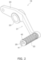
- FIG. 2 is a perspective view of the shift pedal 18.
- FIG. 3 is a top view of the shift pedal 18.
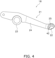
- FIG. 4 is a side view of the shift pedal 18.
- the shift pedal 18 includes a pedal body 21 and a cover 22.
- the pedal body 21 is rotatably attached to the vehicle body 2.
- the pedal body 21 is made of metal such as aluminum.
- FIG. 5 is a perspective view of the pedal body 21.
- the pedal body 21 includes a shaft portion 23, an arm portion 24, and a pedal tread portion 25.
- the shaft portion 23 is rotatably supported by the vehicle body 2.
- the shaft portion 23 projects laterally from the arm portion 24.
- the arm portion 24 has a plate shape.
- the arm portion 24 extends from the shaft portion 23 in the front-rear direction.
- FIGS. 6 to 8 are enlarged views of the pedal body 21 showing the vicinity of the pedal tread portion 25.
- the pedal tread portion 25 projects laterally from the arm portion 24.
- the pedal tread portion 25 is made of sheet metal.
- the pedal tread portion 25 is connected to the arm portion 24 by, for example, welding.
- the pedal tread portion 25 has a plate shape that is bent convexly upward.
- the pedal tread portion 25 includes an inner lateral portion 26 and an outer lateral portion 27.
- the inner lateral portion 26 is connected to the arm portion 24.
- the outer lateral portion 27 is arranged further laterally outward than the inner lateral portion 26.
- the outer lateral portion 27 of the pedal tread portion 25 includes a pedal end 28.
- the pedal end 28 is located at the outermost lateral side of the pedal tread portion 25.
- the outer lateral portion 27 has the same width as the inner lateral portion 26 in the front-rear direction of the vehicle.
- the outer lateral portion 27 and the inner lateral portion 26 have a maximum width in the pedal tread portion 25 in the front-rear direction of the vehicle.
- the pedal tread portion 25 includes an upper surface 31, a bottom surface 32, a first edge 33, and a second edge 34.
- the upper surface 31 has a curved shape convexly upward.
- the bottom surface 32 has a curved shape concave upward.
- the first edge 33 and the second edge 34 extend in the left-right direction of the vehicle.
- the first edge 33 and the second edge 34 extend linearly.
- the second edge 34 is located opposite the first edge 33.
- the first edge 33 is located on the front side of the pedal tread portion 25, and the second edge 34 is located on the rear side of the pedal tread portion 25. As shown in FIG. 6 , the corner 35 between the first edge 33 and the pedal end 28 is rounded.
- the corner 36 between the second edge 34 and the pedal end 28 is rounded.
- the pedal tread portion 25 includes a first notch 37 and a second notch 38.
- the first notch 37 is provided in the first edge 33.
- the first notch 37 has a shape recessed rearward from the first edge 33.
- the first notch 37 is arranged facing forward.
- the second notch 38 is provided in the second edge 34.
- the second notch 38 has a shape recessed forward from the second edge 34.
- the second notch 38 is arranged facing rearward.
- the first notch 37 and the second notch 38 are arranged between the inner lateral portion 26 and the outer lateral portion 27.
- the first notch 37 and the second notch 38 are arranged side by side in the front-rear direction of the vehicle.
- the first notch 37 and the second notch 38 are arranged on the outer lateral side of the center of the pedal tread portion 25 in the left-right direction of the vehicle.
- the first notch 37 and the second notch 38 have a smoothly curved shape.
- the pedal body 21 includes a reinforcing member 39.
- the reinforcing member 39 projects laterally from the arm portion 24.
- the reinforcing member 39 has a cylindrical shape.
- the reinforcing member 39 is connected to the arm portion 24 by, for example, welding.
- the reinforcing member 39 is arranged below the pedal tread portion 25.
- the reinforcing member 39 is in contact with the bottom surface 32 of the pedal tread portion 25.
- the reinforcing member 39 supports the pedal tread portion 25 from below.
- the cover 22 is separate from the pedal body 21.
- the cover 22 is attached to the pedal body 21.
- the cover 22 is made of an elastic material such as rubber.
- the cover 22 covers the pedal tread portion 25.
- FIG. 9 is an enlarged view of the shift pedal 18 showing the cover 22 and the vicinity of the pedal tread portion 25.
- FIG. 10 is a perspective view of the cover 22. As shown in FIGS. 9 and 10 , the cover 22 has a flattened shape that is longer in the front-rear direction than in the vertical direction.
- the cover 22 includes a cover end 41 and a hole 42.
- the cover end 41 is located at the outermost lateral side of the cover 22.
- the hole 42 extends in the left-right direction.
- the hole 42 penetrates the cover 22 in the left-right direction.
- the hole 42 is open at the cover end 41. Similar to the pedal tread portion 25, the hole 42 has a bent shape convexly upward.
- the hole 42 includes an upper inner surface 43, a lower inner surface 44, a front inner surface 45, and a rear inner surface 46.
- the upper inner surface 43 is curved convexly upward.
- the lower inner surface 44 is curved convexly upward.
- the hole 42 extends in a curved line from the front inner surface 45 toward the rear inner surface 46.
- the pedal tread portion 25 is inserted into the hole 42.
- the pedal tread portion 25 is press-fitted into the hole 42. Thereby, the cover 22 is attached to the pedal body 21.
- the upper surface 31 of the pedal tread portion 25 contacts the upper inner surface 43.
- the bottom surface 32 of the pedal tread portion 25 contacts the lower inner surface 44.
- the first edge 33 of the pedal tread portion 25 contacts the front inner surface 45.
- the second edge 34 contacts the rear inner surface 46.
- the cover 22 includes an upper curved surface 47 and a lower curved surface 48.
- the upper curved surface 47 is provided on the upper surface of the cover 22.
- the upper curved surface 47 is curved convexly upward.
- the lower curved surface 48 is provided on the lower surface of the cover 22.
- the lower curved surface 48 is curved convexly downward.
- the upper curved surface 47 and the lower curved surface 48 are provided with anti-slip grooves.
- the curvature of the lower curved surface 48 is greater than the curvature of the upper curved surface 47.
- the cover 22 includes a lower cover portion 51 and an upper cover portion 52.
- the lower cover portion 51 is located below the pedal tread portion 25.
- the lower cover portion 51 is arranged facing the bottom surface 32 of the pedal tread portion 25.
- the upper cover portion 52 is located above the pedal tread portion 25.
- the upper cover portion 52 is arranged facing the upper surface 31 of the pedal tread portion 25.
- the thickness of the lower cover portion 51 in the vertical direction is larger than the thickness of the upper cover portion 52 in the vertical direction.
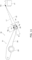
- a contact point between a first tangent line L1 and the cover 22 is defined as an upper contact point P1 as seen in the vehicle side view.
- the first tangent line L1 passes through a predetermined position P3 on the foot step 17 and contacts the cover 22 from above.
- the predetermined position P3 is, for example, the front end of the upper surface of the foot step 17. Alternatively, the predetermined position P3 may be any other position on the upper surface of the foot step 17.
- a contact point between a second tangent line L2 and the cover 22 is defined as a lower contact point P2.
- the second tangent line L2 passes through the predetermined position P3 on the foot step 17 and contacts the cover 22 from below.
- a direction in which a straight line L3 connecting the upper contact point P1 and the lower contact point P2 extends is defined as an operating direction A1 of a rider's foot.
- a dimension S1 of the cover 22 in the operating direction A1 is smaller than a dimension S2 of the cover 22 in a direction perpendicular to the operating direction A1.
- FIG. 12 is a sectional view taken along the line XII-XII of the shift pedal 18 in FIG. 9 .
- the pedal tread portion 25 is arranged within the hole 42.
- the pedal end 28 is arranged further laterally inward than the cover end 41.
- the cover 22 includes a first protrusion 53 and a second protrusion 54.
- the first protrusion 53 and the second protrusion 54 protrude from the inner surface of the hole 42.
- the first protrusion 53 protrudes from the front inner surface 45.
- the first protrusion 53 is engaged with the first notch 37 within the hole 42.
- the second protrusion 54 protrudes from the rear inner surface 46.
- the second protrusion 54 is engaged with the second notch 38 within the hole 42. Thereby, the cover 22 is prevented from coming off from the pedal tread portion 25.
- the pedal tread portion 25 is made of sheet metal and has a bent shape convexly upward. Therefore, compared to the case where the pedal tread portion 25 is cylindrical, the thickness of the pedal tread portion 25 can be made thinner while suppressing a decrease in rigidity. Further, due to the shape of the pedal tread portion 25 described above, it is possible to provide a large thickness of the portion of the cover 22 located below the pedal tread portion 25 while suppressing the overall thickness of the cover 22 from increasing. This improves the operability of the shift pedal 18 while suppressing deterioration in cushioning properties.
- the straddled vehicle 1 is not limited to an off-road type, but may be another type of vehicle such as a street type or a moped.
- the shape of the shift pedal 18 is not limited to that of the embodiment described above, and may be changed.
- FIG. 13 is a sectional view of a shift pedal 18 according to a modification. As shown in FIG. 13 , the pedal end 28 may be disposed flush with the cover end 41.
- the shape of the pedal tread portion 25 is not limited to that of the above embodiment, and may be changed. In the pedal tread portion 25, the first notch 37 and the second notch 38 may be omitted.
- the shape of the cover 22 is not limited to that of the above embodiment, and may be changed. In the cover 22, the first protrusion 53 and the second protrusion 54 may be omitted.
Landscapes
- Engineering & Computer Science (AREA)
- Mechanical Engineering (AREA)
- Chemical & Material Sciences (AREA)
- Combustion & Propulsion (AREA)
- Transportation (AREA)
- Arrangement Or Mounting Of Control Devices For Change-Speed Gearing (AREA)
Abstract
Description
- The present invention relates to a straddled vehicle.
- Some straddled vehicles are equipped with a shift pedal. The shift pedal is rotatably attached to the straddled vehicle. A rider changes gears in the transmission by operating the shift pedal with his or her foot. For example, as in
Japan Registered Utility Model Publication No. 3007864 - As described above, when the shift pedal is cylindrical, the rider's foot moves a long distance when operating the shift pedal. In order to improve the operability of the shift pedal, it is desirable that the rider's foot moves a small distance when operating the shift pedal. However, when the diameter of the pedal tread portion is reduced, the rigidity of the shift pedal is reduced. Furthermore, if the cover is made thin, the cushioning properties for the rider's foot will be reduced. An object of the present invention is to improve the operability of the shift pedal while suppressing a decrease in the rigidity of the shift pedal and a decrease in cushioning properties of the cover.
- A straddled vehicle according to one aspect of the present invention includes a vehicle body and a shift pedal. The shift pedal is attached to the vehicle body. The shift pedal includes a shaft portion, an arm portion, a pedal tread portion, and a cover. The shaft portion is rotatably supported by the vehicle body. The arm portion extends in a front-rear direction of the vehicle from the shaft portion. The pedal tread portion projects laterally from the arm portion. The cover is made of an elastic material and covers the pedal tread portion. The pedal tread portion is made of sheet metal and has an upwardly convex bent shape.
- According to the straddled vehicle according to the present aspect, the pedal tread portion is made of sheet metal and has an upwardly convex bent shape. Therefore, compared to a case where the pedal tread portion is cylindrical, the thickness of the pedal tread portion can be made thinner while suppressing a decrease in rigidity. Further, due to the shape of the pedal tread portion described above, it is possible to provide a large thickness of the portion of the cover located below the pedal tread portion while suppressing an increase in the thickness of the entire cover. This improves shift pedal operability while suppressing deterioration in cushioning properties.
- The bottom surface of the pedal tread portion may have an upwardly concave shape. In this case, the thickness of the portion of the cover located below the pedal tread portion can be provided to be large. This improves cushioning properties.
- The cover may include a lower cover portion and an upper cover portion. The lower cover portion may be located below the pedal tread portion. The upper cover portion may be located above the pedal tread portion. The thickness of the lower cover portion in the vertical direction may be larger than the thickness of the upper cover portion in the vertical direction. In this case, cushioning properties when operating the shift pedal are improved.
- The cover may include an upper curved surface and a lower curved surface. The upper curved surface may be provided on the upper surface of the cover and may be curved convexly upward. The lower curved surface may be provided on the lower surface of the cover and curved convexly downward. In this case, cushioning properties when operating the shift pedal are improved.
- The curvature of the lower curved surface may be greater than the curvature of the upper curved surface. In this case, the shift pedal can be made thinner while improving the cushioning properties when operating the shift pedal. This improves the operability of the shift pedal.
- The straddled vehicle may further include a foot step. The foot step may be located behind the shift pedal. As seen in the vehicle side view, a point of contact between the cover and a first tangent line that passes through a predetermined position on the foot step and contacts the cover from above is defined as an upper contact point. As seen in the vehicle side view, a point of contact between the cover and a second tangent line that passes through the predetermined position on the foot step and contacts the cover from below is defined as a lower contact point. As seen in the vehicle side view, a direction in which a straight line connecting the upper contact point and the lower contact point extends is defined as an operating direction of the rider's foot. As seen in the vehicle side view, a dimension of the cover in the operating direction may be smaller than a dimension of the cover in a direction perpendicular to the operating direction. In this case, the shift pedal operability is improved by reducing a distance of foot movement.
-
-
FIG. 1 is a side view of a straddled vehicle according to an embodiment. -
FIG. 2 is a perspective view of a shift pedal. -
FIG. 3 is a top view of the shift pedal. -
FIG. 4 is a side view of the shift pedal. -
FIG. 5 is a perspective view of a pedal body. -
FIG. 6 is an enlarged view of the pedal body showing q vicinity of a pedal tread portion. -
FIG. 7 is an enlarged view of the pedal body showing the vicinity of the pedal tread portion. -
FIG. 8 is an enlarged view of the pedal body showing the vicinity of the pedal tread portion. -
FIG. 9 is an enlarged view of the shift pedal showing a cover and the vicinity of the pedal tread portion. -
FIG. 10 is a perspective view of the cover. -
FIG. 11 is a side view of the shift pedal showing a definition of an operating direction of the shift pedal. -
FIG. 12 is a sectional view taken along line XII-XII of the shift pedal inFIG. 9 . -
FIG. 13 is a sectional view of a shift pedal according to a modified example. Embodiments of the invention - Hereinafter, a straddled vehicle according to an embodiment will be described with reference to the drawings.
FIG. 1 is a side view of a straddledvehicle 1 according to an embodiment. The straddledvehicle 1 is a so-called off-road type motorcycle. As shown inFIG. 1 , the straddledvehicle 1 includes a vehicle body 2. The vehicle body 2 includes asteering device 3, a front wheel 4, aseat 5, apower unit 6, arear wheel 7, aswing arm 8, and avehicle body frame 9. In the present embodiment, the front, rear, left, and right directions refer to the front, rear, left, and right directions as viewed from a rider seated on theseat 5. - The
vehicle body frame 9 includes ahead pipe 11 and amain frame 12. Thehead pipe 11 extends forward and downward. Themain frame 12 is connected to thehead pipe 11. - The
steering device 3 is rotatably supported by thehead pipe 11. Thesteering device 3 is configured to be steered by a rider. Thesteering device 3 includes afront fork 13 and ahandle member 14. Thefront fork 13 rotatably supports the front wheel 4. Thefront fork 13 is rotatably supported by thehead pipe 11. Thehandle member 14 is connected to thefront fork 13. Thehandle member 14 is operable left and right by a rider. - The
seat 5 is arranged behind thehead pipe 11. Theseat 5 is supported by thevehicle body frame 9. Thepower unit 6 is arranged below theseat 5. Thepower unit 6 is supported by themain frame 12. Thepower unit 6 generates driving force to rotate therear wheel 7. Thepower unit 6 includes anengine 15 and atransmission 16. - The
rear wheel 7 is arranged behind thepower unit 6. Therear wheel 7 is connected to themain frame 12 via theswing arm 8. Theswing arm 8 is swingably supported by themain frame 12. Therear wheel 7 is rotatably supported by theswing arm 8. - A
foot step 17 and ashift pedal 18 are arranged below theseat 5. Thefoot step 17 is arranged behind theshift pedal 18. A rider's foot is placed on thefoot step 17. Thefoot step 17 is connected to themain frame 12. Thefoot step 17 projects laterally from themain frame 12. - The
shift pedal 18 is rotatably attached to the vehicle body 2. Theshift pedal 18 is attached to thetransmission 16, for example. Note that theshift pedal 18 is not limited to be attached to thetransmission 16, and may be attached to other parts such as thevehicle body frame 9. Theshift pedal 18 is operated by a rider's foot. By operating theshift pedal 18, the gear of thetransmission 16 is changed. -
FIG. 2 is a perspective view of theshift pedal 18.FIG. 3 is a top view of theshift pedal 18.FIG. 4 is a side view of theshift pedal 18. As shown inFIGS. 2 to 4 , theshift pedal 18 includes apedal body 21 and acover 22. Thepedal body 21 is rotatably attached to the vehicle body 2. Thepedal body 21 is made of metal such as aluminum. -
FIG. 5 is a perspective view of thepedal body 21. As shown inFIG. 5 , thepedal body 21 includes ashaft portion 23, anarm portion 24, and apedal tread portion 25. Theshaft portion 23 is rotatably supported by the vehicle body 2. Theshaft portion 23 projects laterally from thearm portion 24. Thearm portion 24 has a plate shape. Thearm portion 24 extends from theshaft portion 23 in the front-rear direction. -
FIGS. 6 to 8 are enlarged views of thepedal body 21 showing the vicinity of thepedal tread portion 25. As shown inFIGS. 6 to 8 , thepedal tread portion 25 projects laterally from thearm portion 24. Thepedal tread portion 25 is made of sheet metal. Thepedal tread portion 25 is connected to thearm portion 24 by, for example, welding. Thepedal tread portion 25 has a plate shape that is bent convexly upward. - As shown in
FIG. 6 , thepedal tread portion 25 includes aninner lateral portion 26 and an outerlateral portion 27. Theinner lateral portion 26 is connected to thearm portion 24. The outerlateral portion 27 is arranged further laterally outward than theinner lateral portion 26. The outerlateral portion 27 of thepedal tread portion 25 includes apedal end 28. Thepedal end 28 is located at the outermost lateral side of thepedal tread portion 25. The outerlateral portion 27 has the same width as theinner lateral portion 26 in the front-rear direction of the vehicle. The outerlateral portion 27 and theinner lateral portion 26 have a maximum width in thepedal tread portion 25 in the front-rear direction of the vehicle. - The
pedal tread portion 25 includes anupper surface 31, abottom surface 32, afirst edge 33, and asecond edge 34. Theupper surface 31 has a curved shape convexly upward. Thebottom surface 32 has a curved shape concave upward. Thefirst edge 33 and thesecond edge 34 extend in the left-right direction of the vehicle. Thefirst edge 33 and thesecond edge 34 extend linearly. Thesecond edge 34 is located opposite thefirst edge 33. Thefirst edge 33 is located on the front side of thepedal tread portion 25, and thesecond edge 34 is located on the rear side of thepedal tread portion 25. As shown inFIG. 6 , thecorner 35 between thefirst edge 33 and thepedal end 28 is rounded. Thecorner 36 between thesecond edge 34 and thepedal end 28 is rounded. - The
pedal tread portion 25 includes afirst notch 37 and asecond notch 38. Thefirst notch 37 is provided in thefirst edge 33. Thefirst notch 37 has a shape recessed rearward from thefirst edge 33. Thefirst notch 37 is arranged facing forward. Thesecond notch 38 is provided in thesecond edge 34. Thesecond notch 38 has a shape recessed forward from thesecond edge 34. Thesecond notch 38 is arranged facing rearward. - The
first notch 37 and thesecond notch 38 are arranged between theinner lateral portion 26 and the outerlateral portion 27. Thefirst notch 37 and thesecond notch 38 are arranged side by side in the front-rear direction of the vehicle. Thefirst notch 37 and thesecond notch 38 are arranged on the outer lateral side of the center of thepedal tread portion 25 in the left-right direction of the vehicle. Thefirst notch 37 and thesecond notch 38 have a smoothly curved shape. - The
pedal body 21 includes a reinforcingmember 39. The reinforcingmember 39 projects laterally from thearm portion 24. The reinforcingmember 39 has a cylindrical shape. The reinforcingmember 39 is connected to thearm portion 24 by, for example, welding. The reinforcingmember 39 is arranged below thepedal tread portion 25. The reinforcingmember 39 is in contact with thebottom surface 32 of thepedal tread portion 25. The reinforcingmember 39 supports thepedal tread portion 25 from below. - The
cover 22 is separate from thepedal body 21. Thecover 22 is attached to thepedal body 21. Thecover 22 is made of an elastic material such as rubber. Thecover 22 covers thepedal tread portion 25.FIG. 9 is an enlarged view of theshift pedal 18 showing thecover 22 and the vicinity of thepedal tread portion 25.FIG. 10 is a perspective view of thecover 22. As shown inFIGS. 9 and10 , thecover 22 has a flattened shape that is longer in the front-rear direction than in the vertical direction. - The
cover 22 includes acover end 41 and ahole 42. Thecover end 41 is located at the outermost lateral side of thecover 22. Thehole 42 extends in the left-right direction. Thehole 42 penetrates thecover 22 in the left-right direction. Thehole 42 is open at thecover end 41. Similar to thepedal tread portion 25, thehole 42 has a bent shape convexly upward. - The
hole 42 includes an upperinner surface 43, a lowerinner surface 44, a frontinner surface 45, and a rearinner surface 46. The upperinner surface 43 is curved convexly upward. The lowerinner surface 44 is curved convexly upward. Thehole 42 extends in a curved line from the frontinner surface 45 toward the rearinner surface 46. Thepedal tread portion 25 is inserted into thehole 42. Thepedal tread portion 25 is press-fitted into thehole 42. Thereby, thecover 22 is attached to thepedal body 21. Theupper surface 31 of thepedal tread portion 25 contacts the upperinner surface 43. Thebottom surface 32 of thepedal tread portion 25 contacts the lowerinner surface 44. Thefirst edge 33 of thepedal tread portion 25 contacts the frontinner surface 45. Thesecond edge 34 contacts the rearinner surface 46. - The
cover 22 includes an uppercurved surface 47 and a lowercurved surface 48. The uppercurved surface 47 is provided on the upper surface of thecover 22. The uppercurved surface 47 is curved convexly upward. The lowercurved surface 48 is provided on the lower surface of thecover 22. The lowercurved surface 48 is curved convexly downward. The uppercurved surface 47 and the lowercurved surface 48 are provided with anti-slip grooves. The curvature of the lowercurved surface 48 is greater than the curvature of the uppercurved surface 47. - The
cover 22 includes alower cover portion 51 and anupper cover portion 52. Thelower cover portion 51 is located below thepedal tread portion 25. Thelower cover portion 51 is arranged facing thebottom surface 32 of thepedal tread portion 25. Theupper cover portion 52 is located above thepedal tread portion 25. Theupper cover portion 52 is arranged facing theupper surface 31 of thepedal tread portion 25. The thickness of thelower cover portion 51 in the vertical direction is larger than the thickness of theupper cover portion 52 in the vertical direction. - As shown in
FIG. 11 , a contact point between a first tangent line L1 and thecover 22 is defined as an upper contact point P1 as seen in the vehicle side view. The first tangent line L1 passes through a predetermined position P3 on thefoot step 17 and contacts thecover 22 from above. The predetermined position P3 is, for example, the front end of the upper surface of thefoot step 17. Alternatively, the predetermined position P3 may be any other position on the upper surface of thefoot step 17. As seen in the vehicle side view, a contact point between a second tangent line L2 and thecover 22 is defined as a lower contact point P2. The second tangent line L2 passes through the predetermined position P3 on thefoot step 17 and contacts thecover 22 from below. As seen in the vehicle side view, a direction in which a straight line L3 connecting the upper contact point P1 and the lower contact point P2 extends is defined as an operating direction A1 of a rider's foot. As shown inFIG. 11 , as seen in the vehicle side view, a dimension S1 of thecover 22 in the operating direction A1 is smaller than a dimension S2 of thecover 22 in a direction perpendicular to the operating direction A1. -
FIG. 12 is a sectional view taken along the line XII-XII of theshift pedal 18 inFIG. 9 . As shown inFIG. 12 , thepedal tread portion 25 is arranged within thehole 42. Thepedal end 28 is arranged further laterally inward than thecover end 41. Thecover 22 includes afirst protrusion 53 and asecond protrusion 54. Thefirst protrusion 53 and thesecond protrusion 54 protrude from the inner surface of thehole 42. Thefirst protrusion 53 protrudes from the frontinner surface 45. Thefirst protrusion 53 is engaged with thefirst notch 37 within thehole 42. Thesecond protrusion 54 protrudes from the rearinner surface 46. Thesecond protrusion 54 is engaged with thesecond notch 38 within thehole 42. Thereby, thecover 22 is prevented from coming off from thepedal tread portion 25. - According to the straddled
vehicle 1 according to the present embodiment, thepedal tread portion 25 is made of sheet metal and has a bent shape convexly upward. Therefore, compared to the case where thepedal tread portion 25 is cylindrical, the thickness of thepedal tread portion 25 can be made thinner while suppressing a decrease in rigidity. Further, due to the shape of thepedal tread portion 25 described above, it is possible to provide a large thickness of the portion of thecover 22 located below thepedal tread portion 25 while suppressing the overall thickness of thecover 22 from increasing. This improves the operability of theshift pedal 18 while suppressing deterioration in cushioning properties. - Although one embodiment of the present invention has been described above, the present invention is not limited to the above embodiment, and various changes can be made without departing from the gist of the invention.
- The straddled
vehicle 1 is not limited to an off-road type, but may be another type of vehicle such as a street type or a moped. The shape of theshift pedal 18 is not limited to that of the embodiment described above, and may be changed.FIG. 13 is a sectional view of ashift pedal 18 according to a modification. As shown inFIG. 13 , thepedal end 28 may be disposed flush with thecover end 41. - The shape of the
pedal tread portion 25 is not limited to that of the above embodiment, and may be changed. In thepedal tread portion 25, thefirst notch 37 and thesecond notch 38 may be omitted. The shape of thecover 22 is not limited to that of the above embodiment, and may be changed. In thecover 22, thefirst protrusion 53 and thesecond protrusion 54 may be omitted. - 2: Vehicle body, 17: Foot step, 18: Shift pedal, 22: Cover, 23: Shaft portion, 24: Arm portion, 25: Pedal tread portion, 47: Upper curved surface, 48: Lower curved surface, 51: Lower cover portion, 52: Upper cover portion, A1: Operating direction, L1: First tangent line, L2: Second tangent line, P1: Upper contact point, P2: Lower contact point
Claims (6)
- A straddled vehicle (1) comprising:a vehicle body (2); anda shift pedal (18) attached to the vehicle body (2), whereinthe shift pedal (18) includesa shaft portion (23) rotatably supported by the vehicle body (2),an arm portion (24) extending in a front-rear direction of the vehicle from the shaft portion (23),a pedal tread portion (25) projecting laterally from the arm portion (24), anda cover (22) that is made of an elastic material and covers the pedal tread portion (25), andthe pedal tread portion (25) is made of sheet metal and has an upwardly curved shape.
- The straddled vehicle according to claim 1, wherein
a bottom surface (32) of the pedal tread portion (25) has a shape concave upward. - The straddled vehicle according to claim 1 or 2, whereinthe cover (22) includesa lower cover portion (51) located below the pedal tread portion (25), andan upper cover portion (47) located above the pedal tread portion (25), anda thickness of the lower cover portion (48) in a vertical direction of the vehicle (1) is larger than a thickness of the upper cover portion (47) in the vertical direction.
- The straddled vehicle according to any one of claims 1 to 3, wherein
the cover (22) includesan upper curved surface (47) provided on an upper surface of the cover (22) and curved convexly upward, anda lower curved surface (48) provided on a lower surface of the cover (22) and curved convexly downward. - The straddled vehicle according to claim 4, wherein
a curvature of the lower curved surface (48) is greater than a curvature of the upper curved surface (47). - The straddled vehicle according to any one of claims 1 to 5, further comprising a foot step (17) disposed behind the shift pedal (18), whereinas seen in a vehicle side view, a contact point between the cover (22) and a first tangent line (L1) that passes through a predetermined position on the foot step (17) and contacts the cover (22) from above is defined as an upper contact point (P1),as seen in the vehicle side view, a contact point between the cover (22) and a second tangent line (L2) that passes through the predetermined position on the foot step (17) and contacts the cover (22) from below is defined as a lower contact point (P2),as seen in the vehicle side view, a direction in which a straight line connecting the upper contact point (P1) and the lower contact point (P2) extends is defined as an operating direction of a rider's foot, andas seen in the vehicle side view, a dimension of the cover (22) in the operating direction is smaller than a dimension of the cover (22) in a direction perpendicular to the operating direction.
Applications Claiming Priority (1)
| Application Number | Priority Date | Filing Date | Title |
|---|---|---|---|
| JP2023091564A JP2024173255A (en) | 2023-06-02 | 2023-06-02 | Saddle-type vehicle |
Publications (2)
| Publication Number | Publication Date |
|---|---|
| EP4470894A1 true EP4470894A1 (en) | 2024-12-04 |
| EP4470894B1 EP4470894B1 (en) | 2025-07-23 |
Family
ID=89076206
Family Applications (1)
| Application Number | Title | Priority Date | Filing Date |
|---|---|---|---|
| EP23213936.0A Active EP4470894B1 (en) | 2023-06-02 | 2023-12-04 | Straddled vehicle |
Country Status (3)
| Country | Link |
|---|---|
| EP (1) | EP4470894B1 (en) |
| JP (1) | JP2024173255A (en) |
| CN (1) | CN119058875A (en) |
Citations (5)
| Publication number | Priority date | Publication date | Assignee | Title |
|---|---|---|---|---|
| JPS50137750U (en) * | 1974-04-30 | 1975-11-13 | ||
| JPS58103998U (en) * | 1981-08-28 | 1983-07-15 | 手塚 保夫 | Change pedal that allows you to adjust the pedal position |
| JP3007864U (en) | 1994-08-12 | 1995-02-28 | 川崎重工業株式会社 | Change pedal |
| US8733205B2 (en) * | 2011-01-07 | 2014-05-27 | University Of Akron Research Foundation | Motorcycle gear shifter cover |
| US10730587B2 (en) * | 2018-06-01 | 2020-08-04 | Paul Yaffe | Gearshifter assemblies for motorcycles |
-
2023
- 2023-06-02 JP JP2023091564A patent/JP2024173255A/en active Pending
- 2023-12-04 EP EP23213936.0A patent/EP4470894B1/en active Active
-
2024
- 2024-04-26 CN CN202410511531.0A patent/CN119058875A/en active Pending
Patent Citations (5)
| Publication number | Priority date | Publication date | Assignee | Title |
|---|---|---|---|---|
| JPS50137750U (en) * | 1974-04-30 | 1975-11-13 | ||
| JPS58103998U (en) * | 1981-08-28 | 1983-07-15 | 手塚 保夫 | Change pedal that allows you to adjust the pedal position |
| JP3007864U (en) | 1994-08-12 | 1995-02-28 | 川崎重工業株式会社 | Change pedal |
| US8733205B2 (en) * | 2011-01-07 | 2014-05-27 | University Of Akron Research Foundation | Motorcycle gear shifter cover |
| US10730587B2 (en) * | 2018-06-01 | 2020-08-04 | Paul Yaffe | Gearshifter assemblies for motorcycles |
Also Published As
| Publication number | Publication date |
|---|---|
| CN119058875A (en) | 2024-12-03 |
| EP4470894B1 (en) | 2025-07-23 |
| JP2024173255A (en) | 2024-12-12 |
Similar Documents
| Publication | Publication Date | Title |
|---|---|---|
| EP3398844B1 (en) | Mudguard member for saddled vehicle | |
| JP2004123092A (en) | Body cover structure of saddle type vehicle | |
| JP2012017087A (en) | Saddle-ride type vehicle | |
| JP5604124B2 (en) | Motorcycle | |
| EP4470894B1 (en) | Straddled vehicle | |
| EP4470895B1 (en) | Straddled vehicle | |
| CN110962982A (en) | Swing arm of automatic bicycle | |
| JP5419636B2 (en) | Low-floor vehicle pedal structure | |
| JP2019119438A (en) | Tank cover structure of saddle-riding type vehicle | |
| EP3461729B1 (en) | Fuel tank and method of manufacturing | |
| US12344343B2 (en) | Straddled vehicle | |
| JP2014069596A (en) | Handlebar cover device for two-wheeled vehicle | |
| CN111936344A (en) | Working vehicle | |
| JP6499623B2 (en) | Saddle-type vehicle footrest structure and saddle-type vehicle footboard manufacturing method | |
| CN110979527B (en) | Vehicle fender structure | |
| JP6417179B2 (en) | Saddle riding vehicle | |
| JP2009154843A (en) | Front fender and motorcycle | |
| JP4574381B2 (en) | Step structure for motorcycle driver | |
| JP2011230661A (en) | Saddle-riding type vehicle | |
| JP4987344B2 (en) | Rear grip structure and motorcycle equipped with the same | |
| EP3508388A1 (en) | Brake pedal device and saddle-ride type vehicle | |
| JP2705009B2 (en) | Scooter-type vehicle footrest | |
| US6550564B2 (en) | Saddle-type vehicle with automatic transmission | |
| JP7376558B2 (en) | saddle type vehicle | |
| US20140084643A1 (en) | Grip portion structure for fellow passenger of motorcycle |
Legal Events
| Date | Code | Title | Description |
|---|---|---|---|
| PUAI | Public reference made under article 153(3) epc to a published international application that has entered the european phase |
Free format text: ORIGINAL CODE: 0009012 |
|
| STAA | Information on the status of an ep patent application or granted ep patent |
Free format text: STATUS: REQUEST FOR EXAMINATION WAS MADE |
|
| 17P | Request for examination filed |
Effective date: 20231204 |
|
| AK | Designated contracting states |
Kind code of ref document: A1 Designated state(s): AL AT BE BG CH CY CZ DE DK EE ES FI FR GB GR HR HU IE IS IT LI LT LU LV MC ME MK MT NL NO PL PT RO RS SE SI SK SM TR |
|
| P01 | Opt-out of the competence of the unified patent court (upc) registered |
Free format text: CASE NUMBER: APP_66714/2024 Effective date: 20241217 |
|
| GRAP | Despatch of communication of intention to grant a patent |
Free format text: ORIGINAL CODE: EPIDOSNIGR1 |
|
| STAA | Information on the status of an ep patent application or granted ep patent |
Free format text: STATUS: GRANT OF PATENT IS INTENDED |
|
| RIC1 | Information provided on ipc code assigned before grant |
Ipc: B62K 23/08 20060101AFI20250128BHEP |
|
| INTG | Intention to grant announced |
Effective date: 20250213 |
|
| GRAS | Grant fee paid |
Free format text: ORIGINAL CODE: EPIDOSNIGR3 |
|
| GRAA | (expected) grant |
Free format text: ORIGINAL CODE: 0009210 |
|
| STAA | Information on the status of an ep patent application or granted ep patent |
Free format text: STATUS: THE PATENT HAS BEEN GRANTED |
|
| AK | Designated contracting states |
Kind code of ref document: B1 Designated state(s): AL AT BE BG CH CY CZ DE DK EE ES FI FR GB GR HR HU IE IS IT LI LT LU LV MC ME MK MT NL NO PL PT RO RS SE SI SK SM TR |
|
| REG | Reference to a national code |
Ref country code: GB Ref legal event code: FG4D |
|
| REG | Reference to a national code |
Ref country code: CH Ref legal event code: EP |
|
| REG | Reference to a national code |
Ref country code: DE Ref legal event code: R096 Ref document number: 602023005035 Country of ref document: DE |
|
| REG | Reference to a national code |
Ref country code: IE Ref legal event code: FG4D |
|
| REG | Reference to a national code |
Ref country code: NL Ref legal event code: MP Effective date: 20250723 |
|
| PG25 | Lapsed in a contracting state [announced via postgrant information from national office to epo] |
Ref country code: PT Free format text: LAPSE BECAUSE OF FAILURE TO SUBMIT A TRANSLATION OF THE DESCRIPTION OR TO PAY THE FEE WITHIN THE PRESCRIBED TIME-LIMIT Effective date: 20251124 |
|
| PG25 | Lapsed in a contracting state [announced via postgrant information from national office to epo] |
Ref country code: NL Free format text: LAPSE BECAUSE OF FAILURE TO SUBMIT A TRANSLATION OF THE DESCRIPTION OR TO PAY THE FEE WITHIN THE PRESCRIBED TIME-LIMIT Effective date: 20250723 |
|
| REG | Reference to a national code |
Ref country code: AT Ref legal event code: MK05 Ref document number: 1816179 Country of ref document: AT Kind code of ref document: T Effective date: 20250723 |
|
| PG25 | Lapsed in a contracting state [announced via postgrant information from national office to epo] |
Ref country code: IS Free format text: LAPSE BECAUSE OF FAILURE TO SUBMIT A TRANSLATION OF THE DESCRIPTION OR TO PAY THE FEE WITHIN THE PRESCRIBED TIME-LIMIT Effective date: 20251123 |
|
| PGFP | Annual fee paid to national office [announced via postgrant information from national office to epo] |
Ref country code: DE Payment date: 20251211 Year of fee payment: 3 |
|
| PG25 | Lapsed in a contracting state [announced via postgrant information from national office to epo] |
Ref country code: NO Free format text: LAPSE BECAUSE OF FAILURE TO SUBMIT A TRANSLATION OF THE DESCRIPTION OR TO PAY THE FEE WITHIN THE PRESCRIBED TIME-LIMIT Effective date: 20251023 |
|
| REG | Reference to a national code |
Ref country code: LT Ref legal event code: MG9D |
|
| PG25 | Lapsed in a contracting state [announced via postgrant information from national office to epo] |
Ref country code: AT Free format text: LAPSE BECAUSE OF FAILURE TO SUBMIT A TRANSLATION OF THE DESCRIPTION OR TO PAY THE FEE WITHIN THE PRESCRIBED TIME-LIMIT Effective date: 20250723 |
|
| PG25 | Lapsed in a contracting state [announced via postgrant information from national office to epo] |
Ref country code: FI Free format text: LAPSE BECAUSE OF FAILURE TO SUBMIT A TRANSLATION OF THE DESCRIPTION OR TO PAY THE FEE WITHIN THE PRESCRIBED TIME-LIMIT Effective date: 20250723 |
|
| PG25 | Lapsed in a contracting state [announced via postgrant information from national office to epo] |
Ref country code: HR Free format text: LAPSE BECAUSE OF FAILURE TO SUBMIT A TRANSLATION OF THE DESCRIPTION OR TO PAY THE FEE WITHIN THE PRESCRIBED TIME-LIMIT Effective date: 20250723 |
|
| PGFP | Annual fee paid to national office [announced via postgrant information from national office to epo] |
Ref country code: FR Payment date: 20251229 Year of fee payment: 3 |
|
| PG25 | Lapsed in a contracting state [announced via postgrant information from national office to epo] |
Ref country code: GR Free format text: LAPSE BECAUSE OF FAILURE TO SUBMIT A TRANSLATION OF THE DESCRIPTION OR TO PAY THE FEE WITHIN THE PRESCRIBED TIME-LIMIT Effective date: 20251024 |
|
| PG25 | Lapsed in a contracting state [announced via postgrant information from national office to epo] |
Ref country code: SE Free format text: LAPSE BECAUSE OF FAILURE TO SUBMIT A TRANSLATION OF THE DESCRIPTION OR TO PAY THE FEE WITHIN THE PRESCRIBED TIME-LIMIT Effective date: 20250723 |
|
| PG25 | Lapsed in a contracting state [announced via postgrant information from national office to epo] |
Ref country code: LV Free format text: LAPSE BECAUSE OF FAILURE TO SUBMIT A TRANSLATION OF THE DESCRIPTION OR TO PAY THE FEE WITHIN THE PRESCRIBED TIME-LIMIT Effective date: 20250723 |
|
| PG25 | Lapsed in a contracting state [announced via postgrant information from national office to epo] |
Ref country code: BG Free format text: LAPSE BECAUSE OF FAILURE TO SUBMIT A TRANSLATION OF THE DESCRIPTION OR TO PAY THE FEE WITHIN THE PRESCRIBED TIME-LIMIT Effective date: 20250723 Ref country code: PL Free format text: LAPSE BECAUSE OF FAILURE TO SUBMIT A TRANSLATION OF THE DESCRIPTION OR TO PAY THE FEE WITHIN THE PRESCRIBED TIME-LIMIT Effective date: 20250723 |
|
| PG25 | Lapsed in a contracting state [announced via postgrant information from national office to epo] |
Ref country code: RS Free format text: LAPSE BECAUSE OF FAILURE TO SUBMIT A TRANSLATION OF THE DESCRIPTION OR TO PAY THE FEE WITHIN THE PRESCRIBED TIME-LIMIT Effective date: 20251023 |
|
| PG25 | Lapsed in a contracting state [announced via postgrant information from national office to epo] |
Ref country code: ES Free format text: LAPSE BECAUSE OF FAILURE TO SUBMIT A TRANSLATION OF THE DESCRIPTION OR TO PAY THE FEE WITHIN THE PRESCRIBED TIME-LIMIT Effective date: 20250723 |
|
| PG25 | Lapsed in a contracting state [announced via postgrant information from national office to epo] |
Ref country code: RO Free format text: LAPSE BECAUSE OF FAILURE TO SUBMIT A TRANSLATION OF THE DESCRIPTION OR TO PAY THE FEE WITHIN THE PRESCRIBED TIME-LIMIT Effective date: 20250723 |
|
| PG25 | Lapsed in a contracting state [announced via postgrant information from national office to epo] |
Ref country code: SM Free format text: LAPSE BECAUSE OF FAILURE TO SUBMIT A TRANSLATION OF THE DESCRIPTION OR TO PAY THE FEE WITHIN THE PRESCRIBED TIME-LIMIT Effective date: 20250723 |
|
| PG25 | Lapsed in a contracting state [announced via postgrant information from national office to epo] |
Ref country code: DK Free format text: LAPSE BECAUSE OF FAILURE TO SUBMIT A TRANSLATION OF THE DESCRIPTION OR TO PAY THE FEE WITHIN THE PRESCRIBED TIME-LIMIT Effective date: 20250723 |
|
| PGFP | Annual fee paid to national office [announced via postgrant information from national office to epo] |
Ref country code: IT Payment date: 20251231 Year of fee payment: 3 |
|
| PG25 | Lapsed in a contracting state [announced via postgrant information from national office to epo] |
Ref country code: CZ Free format text: LAPSE BECAUSE OF FAILURE TO SUBMIT A TRANSLATION OF THE DESCRIPTION OR TO PAY THE FEE WITHIN THE PRESCRIBED TIME-LIMIT Effective date: 20250723 |
|
| REG | Reference to a national code |
Ref country code: DE Ref legal event code: R097 Ref document number: 602023005035 Country of ref document: DE |
|
| PG25 | Lapsed in a contracting state [announced via postgrant information from national office to epo] |
Ref country code: SK Free format text: LAPSE BECAUSE OF FAILURE TO SUBMIT A TRANSLATION OF THE DESCRIPTION OR TO PAY THE FEE WITHIN THE PRESCRIBED TIME-LIMIT Effective date: 20250723 Ref country code: EE Free format text: LAPSE BECAUSE OF FAILURE TO SUBMIT A TRANSLATION OF THE DESCRIPTION OR TO PAY THE FEE WITHIN THE PRESCRIBED TIME-LIMIT Effective date: 20250723 |
|
| PLBE | No opposition filed within time limit |
Free format text: ORIGINAL CODE: 0009261 |
|
| STAA | Information on the status of an ep patent application or granted ep patent |
Free format text: STATUS: NO OPPOSITION FILED WITHIN TIME LIMIT |
|
| REG | Reference to a national code |
Ref country code: CH Ref legal event code: L10 Free format text: ST27 STATUS EVENT CODE: U-0-0-L10-L00 (AS PROVIDED BY THE NATIONAL OFFICE) Effective date: 20260604 |
|
| PG25 | Lapsed in a contracting state [announced via postgrant information from national office to epo] |
Ref country code: LT Free format text: LAPSE BECAUSE OF FAILURE TO SUBMIT A TRANSLATION OF THE DESCRIPTION OR TO PAY THE FEE WITHIN THE PRESCRIBED TIME-LIMIT Effective date: 20250723 |
|
| 26N | No opposition filed |
Effective date: 20260424 |
|
| PG25 | Lapsed in a contracting state [announced via postgrant information from national office to epo] |
Ref country code: MC Free format text: LAPSE BECAUSE OF FAILURE TO SUBMIT A TRANSLATION OF THE DESCRIPTION OR TO PAY THE FEE WITHIN THE PRESCRIBED TIME-LIMIT Effective date: 20250723 |