EP4470891A1 - Straddled vehicle - Google Patents
Straddled vehicle Download PDFInfo
- Publication number
- EP4470891A1 EP4470891A1 EP24179263.9A EP24179263A EP4470891A1 EP 4470891 A1 EP4470891 A1 EP 4470891A1 EP 24179263 A EP24179263 A EP 24179263A EP 4470891 A1 EP4470891 A1 EP 4470891A1
- Authority
- EP
- European Patent Office
- Prior art keywords
- fuel tank
- fuel
- protection member
- straddled vehicle
- tank
- Prior art date
- Legal status (The legal status is an assumption and is not a legal conclusion. Google has not performed a legal analysis and makes no representation as to the accuracy of the status listed.)
- Granted
Links
Images





Classifications
-
- B—PERFORMING OPERATIONS; TRANSPORTING
- B62—LAND VEHICLES FOR TRAVELLING OTHERWISE THAN ON RAILS
- B62J—CYCLE SADDLES OR SEATS; AUXILIARY DEVICES OR ACCESSORIES SPECIALLY ADAPTED TO CYCLES AND NOT OTHERWISE PROVIDED FOR, e.g. ARTICLE CARRIERS OR CYCLE PROTECTORS
- B62J35/00—Fuel tanks specially adapted for motorcycles or engine-assisted cycles; Arrangements thereof
-
- B—PERFORMING OPERATIONS; TRANSPORTING
- B62—LAND VEHICLES FOR TRAVELLING OTHERWISE THAN ON RAILS
- B62H—CYCLE STANDS; SUPPORTS OR HOLDERS FOR PARKING OR STORING CYCLES; APPLIANCES PREVENTING OR INDICATING UNAUTHORIZED USE OR THEFT OF CYCLES; LOCKS INTEGRAL WITH CYCLES; DEVICES FOR LEARNING TO RIDE CYCLES
- B62H5/00—Appliances preventing or indicating unauthorised use or theft of cycles; Locks integral with cycles
- B62H5/001—Preventing theft of parts or accessories used on cycles, e.g. lamp, dynamo
-
- B—PERFORMING OPERATIONS; TRANSPORTING
- B62—LAND VEHICLES FOR TRAVELLING OTHERWISE THAN ON RAILS
- B62J—CYCLE SADDLES OR SEATS; AUXILIARY DEVICES OR ACCESSORIES SPECIALLY ADAPTED TO CYCLES AND NOT OTHERWISE PROVIDED FOR, e.g. ARTICLE CARRIERS OR CYCLE PROTECTORS
- B62J11/00—Supporting arrangements specially adapted for fastening specific devices to cycles, e.g. supports for attaching maps
- B62J11/10—Supporting arrangements specially adapted for fastening specific devices to cycles, e.g. supports for attaching maps for mechanical cables, hoses, pipes or electric wires, e.g. cable guides
- B62J11/19—Supporting arrangements specially adapted for fastening specific devices to cycles, e.g. supports for attaching maps for mechanical cables, hoses, pipes or electric wires, e.g. cable guides specially adapted for electric wires
-
- B—PERFORMING OPERATIONS; TRANSPORTING
- B62—LAND VEHICLES FOR TRAVELLING OTHERWISE THAN ON RAILS
- B62J—CYCLE SADDLES OR SEATS; AUXILIARY DEVICES OR ACCESSORIES SPECIALLY ADAPTED TO CYCLES AND NOT OTHERWISE PROVIDED FOR, e.g. ARTICLE CARRIERS OR CYCLE PROTECTORS
- B62J45/00—Electrical equipment arrangements specially adapted for use as accessories on cycles, not otherwise provided for
Definitions
- the present disclosure relates to a straddled vehicle including a fuel tank.
- various electrical elements such as an ECU (Electronic Control Unit), an indicator lamp, a meter unit, a power supply device and an anti-theft device are provided.
- ECU Electronic Control Unit
- an indicator lamp In a straddled vehicle such as a motorcycle, various electrical elements such as an ECU (Electronic Control Unit), an indicator lamp, a meter unit, a power supply device and an anti-theft device are provided.
- Each of these electrical elements is provided in each portion of the straddled vehicle in accordance with the use or function of the electrical element.
- an electrical wire member for power supply or signal transmission is suitably provided among the plurality of electrical elements.
- the electrical element when being provided on the fuel tank, the electrical element projects upwardly from the upper surface of the fuel tank.
- the electrical element may unintentionally come into contact with the body of a rider of the straddled vehicle. Further, it degrades designability of the straddled vehicle.
- a front fork 2 is provided at the head pipe HP to be rotatable about the center axis of the head pipe HP.
- a front wheel 3 is rotatably supported at the lower end portion of the front fork 2.
- a handle 4 is provided at the upper end portion of the front fork 2.
- the main frame 1M supports an engine 5 at a position farther downward than the head pipe HP.
- a fuel tank 10 is provided to be located upwardly of the engine 5 and rearwardly of the head pipe HP.
- a fuel cap device 70 is provided at the substantially center portion of the fuel tank 10 in plan view.
- the fuel cap device 70 is a device for opening and closing a fuel supply port 12c ( Fig. 3 ) of the fuel tank 10 and includes a lid member 71 and a locking device 79. Details of the fuel cap device 70 will be described below.
- a key cylinder 20 is provided forwardly of the fuel tank 10 so as to be located between the fuel tank 10 and the head pipe HP in the forward-and-rearward direction FB. A portion of the upper surface of the fuel tank 10 is covered by a tank cover 90 from above at a position in the vicinity of the key cylinder 20.
- a rear arm 6 is provided to extend rearwardly from a lower portion at the rear end of the main frame 1M.
- the rear arm 6 is supported at the main frame 1M via a pivot shaft.
- a rear wheel 7 is rotatably supported at the rear end portion of the rear arm 6. The rear wheel 7 is rotated as a drive wheel by motive power generated by the engine 5.
- an ECU (Electronic Control Unit) 30 and a battery (not shown) are provided below the seat 8 or below the fuel tank 10, for example. Further, a security device 40 is provided in the vicinity of the key cylinder 20.
- a main harness MH for connecting a plurality of electrical elements to one another is attached to the body frame 1. Further, as shown by the thick dotted lines in Fig. 1 , each of the plurality of electrical elements is connected to the main harness MH by a sub-harness.
- the key cylinder 20, the ECU 30, the security device 40, the fuel cap device 70 and the battery (not shown), described above are electrically connected to one another. In this state, electrical power is supplied from the battery (not shown) to each of the key cylinder 20, the ECU 30, the security device 40 and the fuel cap device 70. Further, various signals are transmitted and received among the ECU 30, the key cylinder 20, the security device 40 and the fuel cap device 70.
- the security device 40 is a so-called immobilizer, and has an electrical circuit that includes a CPU (Central Processing Unit) and a memory, or a microcomputer.
- the security device 40 stores a unique ID (identifier) code.
- the security device 40 reads an ID code stored in the transponder. Further, the security device 40 compares the read ID code with the ID code stored in the security device 40. In a case in which these identification codes match, the security device 40 provides a signal for permitting starting of the engine 5 to the ECU 30. On the other hand, in a case in which the compared two ID codes are different from each other, the security device 40 provides a signal for prohibiting starting of the engine 5 to the ECU 30.
- the ECU 30 In a case in which receiving the signal for permitting starting of the engine 5, the ECU 30 starts the engine 5 in response to a key operation performed by a user. On the other hand, in a case in which receiving the signal for prohibiting starting of the engine 5, the ECU 30 does not respond to a key operation performed by the user and does not start the engine 5.
- the ECU 30 in a case in which receiving the signal for permitting starting of the engine 5, the ECU 30 provides a signal for permitting the user to open and close the fuel supply port 12c ( Fig. 3 ) (hereinafter referred to as a permission signal) to the fuel cap device 70.
- the ECU 30 in a case in which receiving the signal for prohibiting starting of the engine 5, the ECU 30 provides a signal for prohibiting the user from opening and closing the fuel supply port 12c ( Fig. 3 ) (hereinafter referred to as a prohibition signal) to the fuel cap device 70.
- the locking device 79 of the fuel cap device 70 causes the lid member 71 to change to an unlocked state in which the user can perform an operation of opening and closing the fuel supply port 12c ( Fig. 3 ).
- the locking device 79 causes the lid member 71 to change to a locked state in which the user cannot perform an operation of opening and closing the fuel supply port 12c ( Fig. 3 ) and the fuel supply port 12c ( Fig. 2 ) is closed.
- the permission signal and the prohibition signal may be generated by the security device 40. In this case, the security device 40 can directly output the generated permission signal and prohibition signal to the fuel cap device 70.
- Fig. 3 is an exploded view for explaining the configurations of the fuel tank 10 and its peripheral members
- Figs. 4 to 8 are plan views showing a plurality of constituent elements (60, 70, 80, 90) shown in Fig. 3 being sequentially attached onto the fuel tank 10.
- the attachment piece 60, the fuel cap device 70, the protection member 80 and the tank cover 90 are attached onto the fuel tank 10 of the present example.
- the fuel tank 10, the protection member 80 and the tank cover 90 are shown in longitudinal cross-sectional views.
- Each longitudinal cross-sectional view is a longitudinal cross-sectional view of a subject constituent element taken along a vertical plane including the line A-A of Fig. 2 , and the line A-A of Fig. 2 is a vehicle central axis passing through the center of the motorcycle 100 in plan view.
- the fuel tank 10 is formed of a metallic material and includes a tank main body 11, a filler member 12 and a guide pipe 13.
- Fig. 4 shows a plan view of the fuel tank 10.
- the tank main body 11 has an inner space for storing fuel, and is formed in a substantially V-shape in plan view as shown in Fig. 4 .
- an upwardly directed portion of the outer peripheral surface of the tank main body 11 is referred to as an upper surface 11s of the tank main body 11.
- the filler member 12 is provided so as to close the filler opening 11H.
- the filler member 12 is a single member formed of a metallic material, and includes a disc-shaped bottom surface portion 12a and an annular peripheral wall portion 12b extending upwardly from the outer edge of the bottom surface portion 12a by a certain distance. More particularly, the peripheral wall portion 12b has a flat cylindrical shape extending upwardly from the outer edge of the bottom surface portion 12a by the certain distance.
- the circular fuel supply port 12c is formed at a position slightly and rearwardly deviated from the center of the bottom surface portion 12a in plan view.
- the entire circumference of the upper end portion of the peripheral wall portion 12b is connected to the inner edge of the filler opening 11H of the tank main body 11 by welding.
- the guide pipe 13 is formed of a metallic material. As shown in Fig. 3 , the guide pipe 13 is welded to a portion, in which the fuel supply port 12c is formed, of the bottom surface portion 12a of the filler member 12 and extends downwardly from the lower surface of the bottom surface portion 12a by a certain distance. Thus, the inner space of the fuel tank 10 and the external space above the fuel tank 10 communicate with each other through the fuel supply port 12c of the filler member 12 and the inner space of the guide pipe 13.
- Fig. 5 is a plan view showing the attachment piece 60 and the fuel cap device 70 being attached onto the fuel tank 10 of Fig. 4 .
- an enlarged back view of the attachment piece 60 as viewed in the forward direction is shown in the balloon.
- the attachment piece 60 is fabricated by bending of a plurality of portions of a metallic plate-like member extending in a strip shape, for example. Specifically, as shown in the balloon of Fig. 5 , the attachment piece 60 is formed in a rectangular zigzag shape as viewed from a position farther rearward than the attachment piece 60.
- the attachment piece 60 of the present example has three lower portions 61 and two upper portions 62.
- the three lower portions 61 are located at the same height in the upward-and-downward direction UD.
- the two upper portions 62 are located at the same height in the upward-and-downward direction UD.
- each of the two upper portions 62 is located farther upwardly than the three lower portions 61 and between two lower portions 61 adjacent to each other in the leftward-and-rightward direction LR. Further, in each upper portion 62, a screw hole 63 for attachment of the protection member 80, described below, onto the fuel tank 10 is formed.
- the three lower portions 61 of the attachment piece 60 are connected onto the bottom surface portion 12a of the filler member 12 by welding such that the attachment piece 60 is located in the vicinity of the front end portion of the filler member 12.
- the fuel cap device 70 includes the lid member 71 and the locking device 79 of Fig. 1 .
- the fuel cap device 70 is attached to a portion in which the fuel supply port 12c ( Fig. 4 ) is formed in the bottom surface portion 12a of the filler member 12.
- the lid member 71 is put in the unlocked state by the locking device 79, the user can open the fuel supply port 12c by operating the lid member 71.
- the lid member 71 is put in the locked state by the locking device 79, the user cannot open the fuel supply port 12c even when operating the lid member 71.
- One end of the sub-harness LM1 and one end of a breather hose LM2 are connected to the fuel cap device 70. With the fuel cap device 70 being attached onto the fuel tank 10, the sub-harness LM1 and the breather hose LM2 are respectively drawn out forwardly from the fuel cap device 70. The other end of the sub harness LM1 is connected to the main harness MH of Fig. 1 , for example. Thus, various signals are transmitted to the locking device 79, and power is supplied to the locking device 79.
- the fuel tank 10 is formed of a metallic material, when the sub-harness LM1 and the breather hose LM2 come into contact with the upper surface 11s of the fuel tank 10, and vibrate or move freely, the upper surface 11s of the fuel tank 10 may be deteriorated due to friction.
- Fig. 6 is a plan view showing the protection member 80 being attached onto the fuel tank 10 of Fig. 5 .
- the protection member 80 is a substantially plate-like member formed of a resin material, and is screwed onto the two upper portions 62 of the attachment piece 60 of Fig. 5 .
- the sub-harness LM1 and the breather hose LM2 that are drawn out from the fuel cap device 70 are arranged on the protection member 80 so as not to directly come into contact with the upper surface 11s of the fuel tank 10. Thus, the upper surface 11s of the fuel tank 10 is protected.
- the first ribs 85a, 85b, the second ribs 86a, 86b and the third ribs 87a, 87b project respectively and upwardly from the upper surfaces of the plate-like left portion 81, the plate-like center portion 82 and the plate-like right portion 83.
- a substantially center portion of the right first rib 85b is cut away.
- a projection piece 89 extending leftwardly from the upper end portion of the second rib 86b by a certain distance is formed.
- the projection piece 89 overlaps with a cutout portion of the first rib 85b in the forward-and-rearward direction FB.
- an opening 89x is formed in a portion overlapping with the projection piece 89 in plan view.
- the tank cover 90 is attached onto the fuel tank 10 as indicated by the thick solid arrow a4 in Fig. 3 .
- the tank cover 90 has a pair of left and right through holes corresponding to the pair of left and right through holes 88 of the protection member 80 of Fig. 9 in the vicinity of the front end portion thereof. Therefore, at the time of attachment of the tank cover 90, the tank cover 90 is positioned on the fuel tank 10 such that the pair of through holes of the tank cover 90 and the pair of through holes 88 of the protection member 80 overlap with each other. Further, screws are inserted into the pair of through holes of the tank cover 90 and the pair of through holes 88 of the protection member 80, and the tank cover 90 is screwed onto the protection member 80.
- Fig. 8 is a plan view showing the tank cover 90 being attached onto the fuel tank 10 of Fig. 7 .
- the tank cover 90 is formed to cover the entire filler member 12 of the fuel tank 10 and the entire protection member 80 except for the lid member 71 of the fuel cap device 70.
- a portion of the upper surface of the fuel tank 10 according to the present embodiment is formed in a recess shape by the filler member 12.
- the fuel cap device 70 is provided on the bottom surface portion 12a of the filler member 12. That is, a recess portion is formed in the upper surface of the fuel tank 10, and the fuel cap device 70 is provided in the recess portion.
- the above-mentioned fuel tank 10 is formed of a metallic material, and the protection member 80 made of resin is provided between the fuel tank 10, and the sub-harness LM1 and the breather hose LM2. Therefore, deterioration of the upper surface of the fuel tank 10 caused by the contact between the sub-harness LM1 and the breather hose LM2, and the fuel tank 10 is suppressed.
- connection portions connected to the main harness MH provided in the motorcycle 100 are present in the front portion of the vehicle. Therefore, in a case in which the sub harness LM1 extends forwardly of the vehicle, it is possible to shorten the distance from the fuel cap device 70 to the position at which the sub-harness LM1 joins the main harness MH. Therefore, the sub-harness LM1 can be not excessively long and have an appropriately set length.
- the sub-harness LM1 and the breather hose LM2 are guided into the predetermined passage and held by the first rib 85b, the second rib 86b and the projection piece 89.
- the sub-harness LM1 and the breather hose LM2 are prevented from moving out of the predetermined passage in the protection member 80 during traveling of the vehicle. This prevents the sub-harness LM1 and the breather hose LM2 from coming into contact with an unintended portion of the fuel tank 10.
- Fig. 14 is an enlarged plan view of the fuel cap device 70 of Fig. 5 .
- the fuel cap device 70 is divided into three equal portions in the forward-and-rearward direction FB with the fuel cap device 70 provided at the filler member 12 of the fuel tank 10.
- the three equally divided portions of the fuel cap device 70 are referred to as a cap front portion 70a, a cap center portion 70b and a cap rear portion 70c from the front to the rear.
- the sub-harness LM1 and the breather hose LM2 are connected to the cap center portion 70b of the fuel cap device 70 and are drawn out from the center portion.
- Each of the sub-harness LM1 and the breather hose LM2 includes a protection tube or the like for protecting electrical wires or a fluid passage, thereby having a limited bendable range. Therefore, when the sub-harness LM1 and the breather hose LM2 are bent beyond an allowable range, the service life of the sub-harness SL and the breather hose SL may be shortened due to the deformation.
- the paths of the sub-harness LM1 and the breather hose LM2 in the filler member 12 can be elongated as compared to a case in which the sub-harness LM1 and the breather hose LM2 are drawn out from the cap front portion 70a.
- the sub-harness LM1 and the breather hose LM2 are drawn out forwardly of the filler member 12 from the fuel cap device 70, it is not necessary to largely bend the sub-harness LM1 and the breather hose LM2 in the upward-and-downward direction UD.
- the tank cover 90 is provided so as to cover the filler member 12, the protection member 80, the sub-harness LM1 and the breather hose LM2 from above.
- the sub-harness LM1 and the breather hose LM2 are protected by the tank cover.
- the protection member 80 may be screwed to the attachment piece 60, and a portion of the lower surface of the protection member 80 may be connected to the upper surface 11s of the tank main body 11 with an adhesive.
- Fig. 15 is a schematic cross-sectional view showing a first example of the configurations of a fuel tank 10 and its peripheral members according to another embodiment.
- the rear end portion (the portion in which a pair of attachment elongated holes 84 are formed) of a protection member 80 is screwed to the attachment piece 60, and the substantially center portion of the lower surface of the protection member 80 adheres to an upper surface 11s of a tank main body 11 with an adhesive 19.
- the protection member 80 is more firmly attached onto the fuel tank 10.
- the attachment piece 60 may be attached to a portion, which is located forwardly of the filler member 12, of the upper surface of the fuel tank 10 instead of being attached onto the bottom surface portion 12a of the filler member 12.
- Fig. 16 is a schematic cross-sectional view showing a second example of the configurations of a fuel tank 10 and its peripheral members according to another embodiment.
- an attachment piece 60 is attached to a portion, which is located farther forwardly than a filler member 12, of an upper surface 11a of a tank main body 11 instead of being attached to a bottom surface portion 12a of the filler member 12.
- a protection member 80 is screwed to the attachment piece 60.
- at least a fuel cap device 70 is arranged in the filler member 12, and a sub-harness LM1 and a breather hose LM2 are drawn out forwardly on the protection member 80.
- the dimension of the attachment piece 60 of the present example in the height direction (the upward-and-downward direction UD) is made be as small as possible.
- FIG. 17 is a schematic cross-sectional view showing a third example of the configurations of a fuel tank 10 and its peripheral members according to another embodiment.
- a protection member 80 is directly connected onto a tank main body 11 with an adhesive 19, without the above-mentioned attachment piece 60.
- the protection member 80 may be attached onto the upper surface 11s of the tank main body 11 using the attachment piece 60 and an adhesive on the upper surface 11s of the tank main body 11.
- Fig. 18 is a schematic cross-sectional view showing a fourth example of the configurations of a fuel tank 10 and its peripheral members according to another embodiment. In this case, a protection member 80 is more firmly attached onto the fuel tank 10.
- the protection member 80 is formed of a resin material in the motorcycle 100 according to the above-mentioned embodiment, the present disclosure is not limited to this.
- the protection member 80 may be a sheet-like member formed of resin or rubber.
- Fig. 19 is a schematic cross-sectional view showing a fifth example of the configurations of a fuel tank 10 and its peripheral members according to another embodiment.
- a sheet-like member formed of rubber is used as a protection member 80x.
- the protection member 80 is attached onto an upper surface 11s of a tank main body 11 via an adhesive 19. In this case, the protection member 80x has flexibility compared to the metallic protection member 80.
- the protection member 80 deforms in accordance with the deformation of the fuel tank 10. Therefore, the stable attachment state between the fuel tank 10 and the protection member 80 is maintained.
- the protection member 80 is formed of a rubber sheet-like member, it is preferable that a member that guides a sub-harness LM1 and a breather hose LM2 to a predetermined position (passage) on the protection member 80 is provided in a tank cover 90 or the fuel tank 10.
- the security device 40 is provided in the motorcycle 100 according to the above-mentioned embodiment. Further, the locking device 79 of the fuel cap device 70 changes the lid member 71 between the unlocked state and the locked state based on an operation of the security device 40. However, the present disclosure is not limited to this. The locking device 79 may electrically switch the lid member 71 between an unlocked state and a locked state based on an instruction signal provided from an operation device or the like that can be operated by the user, for example.
- another electrical element may be provided in the recess portion formed of the filler member 12.
- the other electrical element includes the key cylinder 20, the security device 40, a display device such as a meter unit or a switching device for turning on and off various functions of the motorcycle 100.
- a sub-harness LM1 for power supply and signal transmission is connected to the other electrical element. Therefore, the sub-harness LM1 connected to other electrical element is drawn out forwardly of the filler member 12 and is arranged on a protection member 80, and thus the same effect as that of the above-mentioned embodiment can be obtained.
- a portion of the fuel tank 10 is formed of the filler member 12, so that the recess portion is formed in a portion of the upper surface of the fuel tank 10.
- the present disclosure is not limited to this.
- a recess portion may be formed in a portion of the upper surface 11s of the tank main body 11 without the filler member 12, and the fuel supply port 12c may be formed in the recess portion. Further, the fuel cap device 70 may be provided in the recess portion.
- an electrical element other than the fuel cap device 70 may be provided in the recess portion.
- the other electrical element includes the key cylinder 20, the security device 40, a display device, a switching device or the like.
- the sub-harness LM1 connected to the other electrical element is drawn out forwardly of the filler member 12 and is arranged on the protection member 80, and thus the same effect as that of the above-mentioned embodiment can be obtained.
- breather hose LM2 While the breather hose LM2 is connected to the fuel cap device 70 in the motorcycle 100 according to the above-mentioned embodiment, the present disclosure is not limited to this.
- the breather hose LM2 does not have to be connected to the fuel cap device 70.
- the motorcycle 100 is an example of a straddled vehicle
- the filler member 12 is an example of a recess portion
- the upper surface 11s and the filler member 12 of the tank main body 11 are examples of an upper surface of a fuel tank
- the fuel tank 10 is an example of a fuel tank
- the fuel cap device 70 is an example of an electrical element
- the sub-harness LM1 is an example of an electrical wire member
- the protection member 80 is an example of a protection member
- the motorcycle 100 is an example of a straddled vehicle.
- the portion, which is located farther rearwardly than the filler member 12, of the upper surface 11s of the tank main body 11 is an example of a first portion
- the maximum height position H1 is an example of a maximum height position of the first portion
- the portion, which is located farther forwardly than the filler member 12, of the upper surface 11s of the tank main body 11 is an example of a second portion
- the maximum height position H2 is an example of a maximum height position of the second portion.
- the recess portion may include a bottom surface portion, and an annular peripheral wall portion that extends upwardly from an outer edge of the bottom surface portion
- a fuel supply port of the fuel tank may be formed in the bottom surface portion
- the electrical element may include a lid member by which the fuel supply port is openable and closable, and a locking device that changes the lid member between a locked state in which the lid member is fixed while closing the fuel supply port and an unlocked state in which the fuel support port is openable and closable based on an electrical signal provided through the electrical wire member.
Landscapes
- Engineering & Computer Science (AREA)
- Mechanical Engineering (AREA)
- Cooling, Air Intake And Gas Exhaust, And Fuel Tank Arrangements In Propulsion Units (AREA)
- Motorcycle And Bicycle Frame (AREA)
Abstract
Description
- The present disclosure relates to a straddled vehicle including a fuel tank.
- In a straddled vehicle such as a motorcycle, various electrical elements such as an ECU (Electronic Control Unit), an indicator lamp, a meter unit, a power supply device and an anti-theft device are provided. Each of these electrical elements is provided in each portion of the straddled vehicle in accordance with the use or function of the electrical element. Further, an electrical wire member for power supply or signal transmission is suitably provided among the plurality of electrical elements.
- There is a straddled vehicle in which a fuel tank and a seat are arranged in this order in an upper portion of the vehicle in a rearward direction of the vehicle. In such a straddled vehicle, provision of an electrical element in the vicinity of the fuel tank, for example, facilitates access to the electrical element and improves maintainability of the electrical element.
- However, when being provided on the fuel tank, the electrical element projects upwardly from the upper surface of the fuel tank. When the height position of the upper end portion of the electrical element is excessively high, the electrical element may unintentionally come into contact with the body of a rider of the straddled vehicle. Further, it degrades designability of the straddled vehicle.
- In a motorcycle described in
JP 2011-31717 A - As described above, in a case in which an electrical element is provided at the upper surface of the fuel tank, an electrical wire member extending from the electrical element may vibrate or freely move on the fuel tank, and thus it may shorten the service life of the fuel tank.
- An object of the present disclosure is to provide a straddled vehicle that can suppress shortening of a service life of a fuel tank caused by an electrical wire member while suppressing large projection of an electrical element farther upward of the fuel tank.
- A straddled vehicle according to one aspect of the present disclosure includes a metallic fuel tank having an upper surface in which a recess portion is formed, an electrical element provided in the recess portion, an electrical wire member provided in association with the electrical element, and a protection member provided between the fuel tank and the electrical wire member.
- With the present disclosure, it is possible to suppress shortening of the service life of a fuel tank caused by an electrical wire member while suppressing large projection of an electrical element farther upward of the fuel tank.
- Other features, elements, characteristics, and advantages of the present disclosure will become more apparent from the following description of preferred embodiments of the present disclosure with reference to the attached drawings.
-
-
Fig. 1 is a one-side view of a motorcycle according to one embodiment of the present disclosure; -
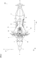
Fig. 2 is a plan view of the motorcycle ofFig. 1 ; -
Fig. 3 is an exploded view for explaining the configuration of a fuel tank and its peripheral members; -
Fig. 4 is a plan view showing a plurality of constituent elements shown inFig. 3 being sequentially attached onto the fuel tank; -
Fig. 5 is a plan view showing the plurality of constituent elements shown inFig. 3 being sequentially attached onto the fuel tank; -
Fig. 6 is a plan view showing the plurality of constituent elements shown inFig. 3 being sequentially attached onto the fuel tank; -
Fig. 7 is a plan view showing the plurality of constituent elements shown inFig. 3 being sequentially attached onto the fuel tank; -
Fig. 8 is a plan view showing the plurality of constituent elements shown inFig. 3 being sequentially attached onto the fuel tank; -
Fig. 9 is a plan view of a protection member ofFig. 6 ; -
Fig. 10 is a one-side view (left side view) of the protection member ofFig. 6 ; -
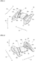
Fig. 11 is a perspective view of the protection member ofFig. 6 as viewed from a position obliquely leftward, forward and upward of the motorcycle; -
Fig. 12 is a perspective view of the protection member ofFig. 6 as viewed from a position obliquely leftward, upward and rearward of the motorcycle; -
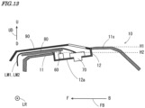
Fig. 13 is a diagram for explaining the effects of the configurations of the fuel tank and its peripheral members according to one embodiment of the present disclosure; -
Fig. 14 is an enlarged plan view of a fuel cap device ofFig. 5 ; -
Fig. 15 is a schematic cross-sectional view showing a first example of the configurations of a fuel tank and its peripheral members according to another embodiment; -
Fig. 16 is a schematic cross-sectional view showing a second example of the configurations of afuel tank 10 and its peripheral members according to another embodiment; -
Fig. 17 is a schematic cross-sectional view showing a third example of the configurations of afuel tank 10 and its peripheral members according to another embodiment; -
Fig. 18 is a schematic cross-sectional view showing a fourth example of the configurations of afuel tank 10 and its peripheral members according to another embodiment; -
Fig. 19 is a schematic cross-sectional view showing a fifth example of the configurations of afuel tank 10 and its peripheral members according to another embodiment; and -
Fig. 20 is a schematic cross-sectional view showing an example of the configurations of a fuel tank and its peripheral members according to a reference embodiment. - A straddled vehicle according to one embodiment of the present disclosure will be described below with reference to the drawings. A motorcycle will be described as one example of the straddled vehicle.
-
Fig. 1 is a one-side view of a motorcycle according to one embodiment of the present disclosure;Fig. 2 is a plan view of themotorcycle 100 ofFig. 1 . In each ofFigs. 1 and2 , themotorcycle 100 standing up to be perpendicular to the road surface is shown. In each ofFig. 1 and subsequent given diagrams, a forward-and-rearward direction FB, a leftward-and-rightward direction LR and an upward-and-downward direction UD of themotorcycle 100 are suitably indicated by arrows. The direction in which the arrow is directed in the forward-and-rearward direction FB is referred to as forward, and its opposite direction is referred to as rearward. Further, the direction in which the arrow is directed in the leftward-and-rightward direction LR is referred to as leftward, and its opposite direction is referred to as rightward. Further, the direction in which the arrow is directed in the upward-and-downward direction UD is referred to as upward, and its opposite direction is referred to as downward. Further, in each ofFig. 1 and subsequent given diagrams, reference characters F, B, L, R, U and D shown together with the arrows indicating directions indicate forward, rearward, leftward, rightward, upward and downward, respectively. - The
motorcycle 100 ofFig. 1 includes ametallic body frame 1. Thebody frame 1 includes a main frame 1M and arear frame 1R. The front end portion of the main frame 1M forms a head pipe HP. The main frame 1M is formed to extend rearwardly and downwardly from the head pipe HP. Therear frame 1R is attached to the main frame 1M so as to extend rearwardly and slightly upwardly from the rear end portion of the main frame 1M and its vicinity. - A
front fork 2 is provided at the head pipe HP to be rotatable about the center axis of the head pipe HP. Afront wheel 3 is rotatably supported at the lower end portion of thefront fork 2. Ahandle 4 is provided at the upper end portion of thefront fork 2. - The main frame 1M supports an
engine 5 at a position farther downward than the head pipe HP. Afuel tank 10 is provided to be located upwardly of theengine 5 and rearwardly of the head pipe HP. As shown inFig. 2 , afuel cap device 70 is provided at the substantially center portion of thefuel tank 10 in plan view. Thefuel cap device 70 is a device for opening and closing afuel supply port 12c (Fig. 3 ) of thefuel tank 10 and includes alid member 71 and alocking device 79. Details of thefuel cap device 70 will be described below. - A
key cylinder 20 is provided forwardly of thefuel tank 10 so as to be located between thefuel tank 10 and the head pipe HP in the forward-and-rearward direction FB. A portion of the upper surface of thefuel tank 10 is covered by atank cover 90 from above at a position in the vicinity of thekey cylinder 20. - A
seat 8 is provided rearwardly of thefuel tank 10. As shown inFig. 1 , thekey cylinder 20, thefuel tank 10 and theseat 8 are supported by thebody frame 1 and are located on the main frame 1M and therear frame 1R. - A
rear arm 6 is provided to extend rearwardly from a lower portion at the rear end of the main frame 1M. Therear arm 6 is supported at the main frame 1M via a pivot shaft. Arear wheel 7 is rotatably supported at the rear end portion of therear arm 6. Therear wheel 7 is rotated as a drive wheel by motive power generated by theengine 5. - In the
motorcycle 100 ofFig. 1 , an ECU (Electronic Control Unit) 30 and a battery (not shown) are provided below theseat 8 or below thefuel tank 10, for example. Further, asecurity device 40 is provided in the vicinity of thekey cylinder 20. - As indicated by the thick two-dots and dash line in
Fig. 1 , in themotorcycle 100 of the present example, a main harness MH for connecting a plurality of electrical elements to one another is attached to thebody frame 1. Further, as shown by the thick dotted lines inFig. 1 , each of the plurality of electrical elements is connected to the main harness MH by a sub-harness. Thus, thekey cylinder 20, theECU 30, thesecurity device 40, thefuel cap device 70 and the battery (not shown), described above, are electrically connected to one another. In this state, electrical power is supplied from the battery (not shown) to each of thekey cylinder 20, theECU 30, thesecurity device 40 and thefuel cap device 70. Further, various signals are transmitted and received among theECU 30, thekey cylinder 20, thesecurity device 40 and thefuel cap device 70. - The
security device 40 is a so-called immobilizer, and has an electrical circuit that includes a CPU (Central Processing Unit) and a memory, or a microcomputer. Thesecurity device 40 stores a unique ID (identifier) code. When a key having a transponder is inserted into thekey cylinder 20 and operated, thesecurity device 40 reads an ID code stored in the transponder. Further, thesecurity device 40 compares the read ID code with the ID code stored in thesecurity device 40. In a case in which these identification codes match, thesecurity device 40 provides a signal for permitting starting of theengine 5 to theECU 30. On the other hand, in a case in which the compared two ID codes are different from each other, thesecurity device 40 provides a signal for prohibiting starting of theengine 5 to theECU 30. - In a case in which receiving the signal for permitting starting of the
engine 5, theECU 30 starts theengine 5 in response to a key operation performed by a user. On the other hand, in a case in which receiving the signal for prohibiting starting of theengine 5, theECU 30 does not respond to a key operation performed by the user and does not start theengine 5. - Further, in the present embodiment, in a case in which receiving the signal for permitting starting of the
engine 5, theECU 30 provides a signal for permitting the user to open and close thefuel supply port 12c (Fig. 3 ) (hereinafter referred to as a permission signal) to thefuel cap device 70. On the other hand, in a case in which receiving the signal for prohibiting starting of theengine 5, theECU 30 provides a signal for prohibiting the user from opening and closing thefuel supply port 12c (Fig. 3 ) (hereinafter referred to as a prohibition signal) to thefuel cap device 70. - In a case in which receiving the permission signal, the locking
device 79 of thefuel cap device 70 causes thelid member 71 to change to an unlocked state in which the user can perform an operation of opening and closing thefuel supply port 12c (Fig. 3 ). On the other hand, in a case in which receiving the prohibition signal, the lockingdevice 79 causes thelid member 71 to change to a locked state in which the user cannot perform an operation of opening and closing thefuel supply port 12c (Fig. 3 ) and thefuel supply port 12c (Fig. 2 ) is closed. Thus, it is possible to prevent vandalism such as insertion of a foreign object into thefuel tank 10, theft of fuel, etc. The permission signal and the prohibition signal, described above, may be generated by thesecurity device 40. In this case, thesecurity device 40 can directly output the generated permission signal and prohibition signal to thefuel cap device 70. -
Fig. 3 is an exploded view for explaining the configurations of thefuel tank 10 and its peripheral members, andFigs. 4 to 8 are plan views showing a plurality of constituent elements (60, 70, 80, 90) shown inFig. 3 being sequentially attached onto thefuel tank 10. As shown inFig. 3 , theattachment piece 60, thefuel cap device 70, theprotection member 80 and thetank cover 90 are attached onto thefuel tank 10 of the present example. In the exploded view ofFig. 3 , thefuel tank 10, theprotection member 80 and thetank cover 90 are shown in longitudinal cross-sectional views. Each longitudinal cross-sectional view is a longitudinal cross-sectional view of a subject constituent element taken along a vertical plane including the line A-A ofFig. 2 , and the line A-A ofFig. 2 is a vehicle central axis passing through the center of themotorcycle 100 in plan view. - The
fuel tank 10 is formed of a metallic material and includes a tankmain body 11, afiller member 12 and aguide pipe 13.Fig. 4 shows a plan view of thefuel tank 10. The tankmain body 11 has an inner space for storing fuel, and is formed in a substantially V-shape in plan view as shown inFig. 4 . In the following description, an upwardly directed portion of the outer peripheral surface of the tankmain body 11 is referred to as anupper surface 11s of the tankmain body 11. - In the substantially center portion of the
upper surface 11s of the tankmain body 11, acircular filler opening 11H that upwardly opens the inner space of the tankmain body 11 is formed. Thefiller member 12 is provided so as to close thefiller opening 11H. Thefiller member 12 is a single member formed of a metallic material, and includes a disc-shapedbottom surface portion 12a and an annularperipheral wall portion 12b extending upwardly from the outer edge of thebottom surface portion 12a by a certain distance. More particularly, theperipheral wall portion 12b has a flat cylindrical shape extending upwardly from the outer edge of thebottom surface portion 12a by the certain distance. - The circular
fuel supply port 12c is formed at a position slightly and rearwardly deviated from the center of thebottom surface portion 12a in plan view. The entire circumference of the upper end portion of theperipheral wall portion 12b is connected to the inner edge of thefiller opening 11H of the tankmain body 11 by welding. With such a configuration, thefuel tank 10 according to the present embodiment has a recess portion formed of thefiller member 12 at the substantially center portion of its upper surface. - The
guide pipe 13 is formed of a metallic material. As shown inFig. 3 , theguide pipe 13 is welded to a portion, in which thefuel supply port 12c is formed, of thebottom surface portion 12a of thefiller member 12 and extends downwardly from the lower surface of thebottom surface portion 12a by a certain distance. Thus, the inner space of thefuel tank 10 and the external space above thefuel tank 10 communicate with each other through thefuel supply port 12c of thefiller member 12 and the inner space of theguide pipe 13. - As indicated by the thick solid arrows a1 and a2 in
Fig. 3 , theattachment piece 60 and thefuel cap device 70 are attached onto thebottom surface portion 12a of thefiller member 12.Fig. 5 is a plan view showing theattachment piece 60 and thefuel cap device 70 being attached onto thefuel tank 10 ofFig. 4 . InFig. 5 , an enlarged back view of theattachment piece 60 as viewed in the forward direction is shown in the balloon. - The
attachment piece 60 is fabricated by bending of a plurality of portions of a metallic plate-like member extending in a strip shape, for example. Specifically, as shown in the balloon ofFig. 5 , theattachment piece 60 is formed in a rectangular zigzag shape as viewed from a position farther rearward than theattachment piece 60. Theattachment piece 60 of the present example has threelower portions 61 and twoupper portions 62. The threelower portions 61 are located at the same height in the upward-and-downward direction UD. The twoupper portions 62 are located at the same height in the upward-and-downward direction UD. Further, each of the twoupper portions 62 is located farther upwardly than the threelower portions 61 and between twolower portions 61 adjacent to each other in the leftward-and-rightward direction LR. Further, in eachupper portion 62, ascrew hole 63 for attachment of theprotection member 80, described below, onto thefuel tank 10 is formed. The threelower portions 61 of theattachment piece 60 are connected onto thebottom surface portion 12a of thefiller member 12 by welding such that theattachment piece 60 is located in the vicinity of the front end portion of thefiller member 12. - As described above, the
fuel cap device 70 includes thelid member 71 and thelocking device 79 ofFig. 1 . Thefuel cap device 70 is attached to a portion in which thefuel supply port 12c (Fig. 4 ) is formed in thebottom surface portion 12a of thefiller member 12. When thelid member 71 is put in the unlocked state by the lockingdevice 79, the user can open thefuel supply port 12c by operating thelid member 71. On the other hand, when thelid member 71 is put in the locked state by the lockingdevice 79, the user cannot open thefuel supply port 12c even when operating thelid member 71. - One end of the sub-harness LM1 and one end of a breather hose LM2 are connected to the
fuel cap device 70. With thefuel cap device 70 being attached onto thefuel tank 10, the sub-harness LM1 and the breather hose LM2 are respectively drawn out forwardly from thefuel cap device 70. The other end of the sub harness LM1 is connected to the main harness MH ofFig. 1 , for example. Thus, various signals are transmitted to thelocking device 79, and power is supplied to thelocking device 79. - Because the
fuel tank 10 is formed of a metallic material, when the sub-harness LM1 and the breather hose LM2 come into contact with theupper surface 11s of thefuel tank 10, and vibrate or move freely, theupper surface 11s of thefuel tank 10 may be deteriorated due to friction. - As such, in the present embodiment, as indicated by the thick solid arrow a3 in
Fig. 3 , theprotection member 80 is attached onto thefuel tank 10.Fig. 6 is a plan view showing theprotection member 80 being attached onto thefuel tank 10 ofFig. 5 . Theprotection member 80 is a substantially plate-like member formed of a resin material, and is screwed onto the twoupper portions 62 of theattachment piece 60 ofFig. 5 . - At the time of attachment, the sub-harness LM1 and the breather hose LM2 that are drawn out from the
fuel cap device 70 are arranged on theprotection member 80 so as not to directly come into contact with theupper surface 11s of thefuel tank 10. Thus, theupper surface 11s of thefuel tank 10 is protected. - Here, the structure of the
protection member 80 will be described.Fig. 9 is a plan view of theprotection member 80 ofFig. 6 , andFig. 10 is a one-side view (left side view) of theprotection member 80 ofFig. 6 .Fig. 11 is a perspective view of theprotection member 80 ofFig. 6 as viewed from a position obliquely leftward, forward and upward of themotorcycle 100, andFig. 12 is a perspective view of theprotection member 80 ofFig. 6 as viewed from a position obliquely leftward, rearward and upward of themotorcycle 100. - As shown in
Fig. 9 , theprotection member 80 includes a plate-likeleft portion 81, a plate-like center portion 82 and a plate-likeright portion 83 that are arranged from the left to the right in plan view. Thecenter portion 82 is formed in a substantially rectangular shape. Two attachment elongated holes 84 are respectively formed in the rear end portion of thecenter portion 82 so as to be arranged in the leftward-and-rightward direction LR with a space therebetween. The two attachmentelongated holes 84 correspond to the two screw holes 63 formed in the twoupper portions 62 of theattachment piece 60 ofFig. 5 , and are used to screw theprotection member 80 to theattachment piece 60 as described above. - The
left portion 81 and theright portion 83 have a bilaterally symmetrical configuration with respect to thecenter portion 82. The length of theleft portion 81 and theright portion 83 in the forward-and-rearward direction FB is longer than the length of thecenter portion 82 in the forward-and-rearward direction FB. In the forward-and-rearward direction FB, thecenter portion 82 is located between the front end portions of theleft portion 81 and theright portion 83, and the rear end portions of theleft portion 81 and theright portion 83. In the vicinity of the front end portions of theleft portion 81 and theright portion 83, a pair of left and right throughholes 88 for attachment of the below-mentionedtank cover 90 onto theprotection member 80 are formed. - In both of the left side portion and right side portion of the
center portion 82, a pair of left and rightfirst ribs first ribs first ribs left portion 81 and the left side portion of theright portion 83, a pair of left and rightsecond ribs second ribs second ribs left portion 81 and the substantially center of theright portion 83, a pair of left and rightthird ribs - As shown in
Figs. 10 ,11 and 12 , thefirst ribs second ribs third ribs left portion 81, the plate-like center portion 82 and the plate-likeright portion 83. A substantially center portion of the rightfirst rib 85b is cut away. In one portion of the rightsecond rib 86b, aprojection piece 89 extending leftwardly from the upper end portion of thesecond rib 86b by a certain distance is formed. Theprojection piece 89 overlaps with a cutout portion of thefirst rib 85b in the forward-and-rearward direction FB. As shown inFig. 9 , in thecenter portion 82 and theright portion 83, anopening 89x is formed in a portion overlapping with theprojection piece 89 in plan view. - In the
protection member 80 having the above-mentioned configuration, the plurality of ribs (85a, 85b, 86a, 86b, 87a, 87b) ensure the strength required for theprotection member 80 to maintain a predetermined shape. Further, in the present example, a space located between thefirst rib 85b and thesecond rib 86b, that are located rightwardly, among the plurality of ribs (85a, 85b, 86a, 86b, 87a, 87b) and below theprojection piece 89 forms a passage for the sub-harness LM1 and the breather hose LM2. That is, thefirst rib 85b, thesecond rib 86b and theprojection piece 89 function as a guide portion that guides the sub-harness LM1 and the breather hose LM2 to the predetermined passage on theprotection member 80. Further, in this case, the cutout portion of thefirst rib 85b, and theopening 89x in thecenter portion 82 and theright portion 83 form a work space for facilitating the accommodation of the sub-harness LM1 and the breather hose LM2 in the above-mentioned passage. -
Fig. 7 shows that the sub-harness LM1 and the breather hose LM2 that are drawn out from thefuel cap device 70 ofFig. 6 are being arranged between thefirst rib 85b and thesecond rib 86b and below theprojection piece 89. In this case, the portions, which are located above thefuel tank 10, of the sub-harness LM1 and the breather hose LM2 are bundled and held in the passage formed of thefirst rib 85b, thesecond rib 86b and theprojection piece 89 of theprotection member 80. - With the sub-harness LM2 and the breather hose LM2 being held in the predetermined passage in the
protection member 80, thetank cover 90 is attached onto thefuel tank 10 as indicated by the thick solid arrow a4 inFig. 3 . - The tank cover 90 has a pair of left and right through holes corresponding to the pair of left and right through
holes 88 of theprotection member 80 ofFig. 9 in the vicinity of the front end portion thereof. Therefore, at the time of attachment of thetank cover 90, thetank cover 90 is positioned on thefuel tank 10 such that the pair of through holes of thetank cover 90 and the pair of throughholes 88 of theprotection member 80 overlap with each other. Further, screws are inserted into the pair of through holes of thetank cover 90 and the pair of throughholes 88 of theprotection member 80, and thetank cover 90 is screwed onto theprotection member 80. -
Fig. 8 is a plan view showing thetank cover 90 being attached onto thefuel tank 10 ofFig. 7 . The tank cover 90 is formed to cover theentire filler member 12 of thefuel tank 10 and theentire protection member 80 except for thelid member 71 of thefuel cap device 70. - (a)
Fig. 13 is a diagram for explaining the effects of the configurations of thefuel tank 10 and its peripheral members according to one embodiment of the present disclosure. InFig. 13 , the configurations of thefuel tank 10 and its peripheral members of themotorcycle 100 ofFig. 1 are shown in a schematic cross-sectional view for facilitating understanding of description. - As shown in
Fig. 13 , a portion of the upper surface of thefuel tank 10 according to the present embodiment is formed in a recess shape by thefiller member 12. Thefuel cap device 70 is provided on thebottom surface portion 12a of thefiller member 12. That is, a recess portion is formed in the upper surface of thefuel tank 10, and thefuel cap device 70 is provided in the recess portion. - Thus, as compared to a case in which the
fuel cap device 70 is provided in a portion, other than thefiller member 12, of the upper surface of thefuel tank 10, large projection of thefuel cap device 70 upward of thefuel tank 10 is suppressed. - Further, the above-mentioned
fuel tank 10 is formed of a metallic material, and theprotection member 80 made of resin is provided between thefuel tank 10, and the sub-harness LM1 and the breather hose LM2. Therefore, deterioration of the upper surface of thefuel tank 10 caused by the contact between the sub-harness LM1 and the breather hose LM2, and thefuel tank 10 is suppressed. - As a result, it is possible to suppress the shortening of the service life of the
fuel tank 10 caused by the sub-harness LM1 and the breather hose LM2 while suppressing large projection of thefuel cap device 70 upward of thefuel tank 10. - (b) The sub-harness LM1 and the breather hose LM2 that are drawn out from the
fuel cap device 70 extend forwardly of thefiller member 12. Here, a maximum height position H1 of a portion, which is located farther rearwardly than thefiller member 12, of the upper surface of thetank 10 is higher than a maximum height position H2 of a portion, which is located farther forwardly than thefiller member 12, of the upper surface of thetank 10. Therefore, as compared to a case in which the sub-harness LM1 and the breather hose LM2 extend rearwardly of thefiller member 12, the height positions of the peripheral members of thefuel tank 10 including the sub-harness LM1, the breather hose LM2 and theprotection member 80 can be lowered. - Further, a relatively large number of connection portions connected to the main harness MH provided in the
motorcycle 100 are present in the front portion of the vehicle. Therefore, in a case in which the sub harness LM1 extends forwardly of the vehicle, it is possible to shorten the distance from thefuel cap device 70 to the position at which the sub-harness LM1 joins the main harness MH. Therefore, the sub-harness LM1 can be not excessively long and have an appropriately set length. - (c) As described above, the
attachment piece 60 for attaching theprotection member 80 onto thefuel tank 10 is connected to thebottom surface portion 12a of thefiller member 12. Thus, as compared with a case in which theattachment piece 60 is provided in a portion, other than thefiller member 12, of the upper surface of thefuel tank 10, the height position of the peripheral members of thefuel tank 10 can be lowered. - (d) In the
protection member 80, the sub-harness LM1 and the breather hose LM2 are guided into the predetermined passage and held by thefirst rib 85b, thesecond rib 86b and theprojection piece 89. In this case, the sub-harness LM1 and the breather hose LM2 are prevented from moving out of the predetermined passage in theprotection member 80 during traveling of the vehicle. This prevents the sub-harness LM1 and the breather hose LM2 from coming into contact with an unintended portion of thefuel tank 10. - (e) The
protection member 80 is formed of a resin material, thereby having flexibility. Thus, even in a case in which thefuel tank 10 contracts or the like with theprotection member 80 being attached to thefuel tank 10, theprotection member 80 deforms in accordance with the deformation of thefuel tank 10. Therefore, the stable attachment state between thefuel tank 10 and theprotection member 80 is maintained. - (f)
Fig. 14 is an enlarged plan view of thefuel cap device 70 ofFig. 5 . As shown inFig. 14 , it is assumed that thefuel cap device 70 is divided into three equal portions in the forward-and-rearward direction FB with thefuel cap device 70 provided at thefiller member 12 of thefuel tank 10. Here, the three equally divided portions of thefuel cap device 70 are referred to as acap front portion 70a, a cap center portion 70b and a caprear portion 70c from the front to the rear. - In this case, in the
fuel cap device 70 according to the present embodiment, the sub-harness LM1 and the breather hose LM2 are connected to the cap center portion 70b of thefuel cap device 70 and are drawn out from the center portion. - Each of the sub-harness LM1 and the breather hose LM2 includes a protection tube or the like for protecting electrical wires or a fluid passage, thereby having a limited bendable range. Therefore, when the sub-harness LM1 and the breather hose LM2 are bent beyond an allowable range, the service life of the sub-harness SL and the breather hose SL may be shortened due to the deformation.
- With the above-mentioned configuration, the paths of the sub-harness LM1 and the breather hose LM2 in the
filler member 12 can be elongated as compared to a case in which the sub-harness LM1 and the breather hose LM2 are drawn out from thecap front portion 70a. Thus, in a case in which the sub-harness LM1 and the breather hose LM2 are drawn out forwardly of thefiller member 12 from thefuel cap device 70, it is not necessary to largely bend the sub-harness LM1 and the breather hose LM2 in the upward-and-downward direction UD. Therefore, it is possible to prevent the sub-harness LM1 and the breather hose LM2 from largely projecting upwardly of thefuel tank 10 while suppressing the shortening of the service lives of the sub-harness LM1 and the breather hose LM2. - (g) On a portion of the upper surface of the
fuel tank 10, thetank cover 90 is provided so as to cover thefiller member 12, theprotection member 80, the sub-harness LM1 and the breather hose LM2 from above. Thus, the sub-harness LM1 and the breather hose LM2 are protected by the tank cover. - (a) In the
motorcycle 100, theprotection member 80 may be screwed to theattachment piece 60, and a portion of the lower surface of theprotection member 80 may be connected to theupper surface 11s of the tankmain body 11 with an adhesive. -
Fig. 15 is a schematic cross-sectional view showing a first example of the configurations of afuel tank 10 and its peripheral members according to another embodiment. In the example ofFig. 15 , the rear end portion (the portion in which a pair of attachment elongatedholes 84 are formed) of aprotection member 80 is screwed to theattachment piece 60, and the substantially center portion of the lower surface of theprotection member 80 adheres to anupper surface 11s of a tankmain body 11 with an adhesive 19. In this case, theprotection member 80 is more firmly attached onto thefuel tank 10. - (b) In the
motorcycle 100, theattachment piece 60 may be attached to a portion, which is located forwardly of thefiller member 12, of the upper surface of thefuel tank 10 instead of being attached onto thebottom surface portion 12a of thefiller member 12. -
Fig. 16 is a schematic cross-sectional view showing a second example of the configurations of afuel tank 10 and its peripheral members according to another embodiment. In the example ofFig. 16 , anattachment piece 60 is attached to a portion, which is located farther forwardly than afiller member 12, of an upper surface 11a of a tankmain body 11 instead of being attached to abottom surface portion 12a of thefiller member 12. Further, aprotection member 80 is screwed to theattachment piece 60. In such a configuration, at least afuel cap device 70 is arranged in thefiller member 12, and a sub-harness LM1 and a breather hose LM2 are drawn out forwardly on theprotection member 80. Thus, it is possible to suppress the shortening of the service life of thefuel tank 10 caused by the sub-harness LM1 and the breather hose LM2 while suppressing large projection of thefuel cap device 70 forward of thefuel tank 10. It is preferable that the dimension of theattachment piece 60 of the present example in the height direction (the upward-and-downward direction UD) is made be as small as possible. - (c) In the
motorcycle 100, theprotection member 80 may be attached onto theupper surface 11s of the tankmain body 11 with an adhesive instead of being attached to theattachment piece 60.Fig. 17 is a schematic cross-sectional view showing a third example of the configurations of afuel tank 10 and its peripheral members according to another embodiment. - In the example of
Fig. 17 , aprotection member 80 is directly connected onto a tankmain body 11 with an adhesive 19, without the above-mentionedattachment piece 60. In this case, it is not necessary to provide theattachment piece 60, so that the number of components can be reduced. Further, it is possible to suppress an increase in height position of theprotection member 80. - (d) In the
motorcycle 100, theprotection member 80 may be attached onto theupper surface 11s of the tankmain body 11 using theattachment piece 60 and an adhesive on theupper surface 11s of the tankmain body 11.Fig. 18 is a schematic cross-sectional view showing a fourth example of the configurations of afuel tank 10 and its peripheral members according to another embodiment. In this case, aprotection member 80 is more firmly attached onto thefuel tank 10. - (e) While the
protection member 80 is formed of a resin material in themotorcycle 100 according to the above-mentioned embodiment, the present disclosure is not limited to this. Theprotection member 80 may be a sheet-like member formed of resin or rubber.Fig. 19 is a schematic cross-sectional view showing a fifth example of the configurations of afuel tank 10 and its peripheral members according to another embodiment. In the present example, a sheet-like member formed of rubber is used as aprotection member 80x. Theprotection member 80 is attached onto anupper surface 11s of a tankmain body 11 via an adhesive 19. In this case, theprotection member 80x has flexibility compared to themetallic protection member 80. Thus, even in a case in which thefuel tank 10 contracts or the like with theprotection member 80 being attached to thefuel tank 10, theprotection member 80 deforms in accordance with the deformation of thefuel tank 10. Therefore, the stable attachment state between thefuel tank 10 and theprotection member 80 is maintained. - In a case in which the
protection member 80 is formed of a rubber sheet-like member, it is preferable that a member that guides a sub-harness LM1 and a breather hose LM2 to a predetermined position (passage) on theprotection member 80 is provided in atank cover 90 or thefuel tank 10. - (f) The
security device 40 is provided in themotorcycle 100 according to the above-mentioned embodiment. Further, the lockingdevice 79 of thefuel cap device 70 changes thelid member 71 between the unlocked state and the locked state based on an operation of thesecurity device 40. However, the present disclosure is not limited to this. The lockingdevice 79 may electrically switch thelid member 71 between an unlocked state and a locked state based on an instruction signal provided from an operation device or the like that can be operated by the user, for example. - (g) In addition to the
fuel cap device 70, on the upper surface of thefuel tank 10, another electrical element may be provided in the recess portion formed of thefiller member 12. Examples of the other electrical element includes thekey cylinder 20, thesecurity device 40, a display device such as a meter unit or a switching device for turning on and off various functions of themotorcycle 100. A sub-harness LM1 for power supply and signal transmission is connected to the other electrical element. Therefore, the sub-harness LM1 connected to other electrical element is drawn out forwardly of thefiller member 12 and is arranged on aprotection member 80, and thus the same effect as that of the above-mentioned embodiment can be obtained. - (h) In the
motorcycle 100 according to the above-mentioned embodiment, a portion of thefuel tank 10 is formed of thefiller member 12, so that the recess portion is formed in a portion of the upper surface of thefuel tank 10. However, the present disclosure is not limited to this. - In the
fuel tank 10, a recess portion may be formed in a portion of theupper surface 11s of the tankmain body 11 without thefiller member 12, and thefuel supply port 12c may be formed in the recess portion. Further, thefuel cap device 70 may be provided in the recess portion. - Further, in a case in which a recess portion not having the fuel supply port 12s is formed in a portion of the
upper surface 11s of the tankmain body 11, an electrical element other than thefuel cap device 70 may be provided in the recess portion. The other electrical element includes thekey cylinder 20, thesecurity device 40, a display device, a switching device or the like. Also in this case, the sub-harness LM1 connected to the other electrical element is drawn out forwardly of thefiller member 12 and is arranged on theprotection member 80, and thus the same effect as that of the above-mentioned embodiment can be obtained. - (l) While the breather hose LM2 is connected to the
fuel cap device 70 in themotorcycle 100 according to the above-mentioned embodiment, the present disclosure is not limited to this. The breather hose LM2 does not have to be connected to thefuel cap device 70. - (i) While the above-mentioned embodiment is an example in which the present disclosure is applied to a motorcycle, the present disclosure is not limited to this. The present disclosure may be applied to another straddled vehicle such as a four-wheeled automobile, a motor tricycle or an ATV (All Terrain Vehicle).
- In the following paragraphs, non-limiting examples of correspondences between various elements recited in the claims below and those described above with respect to various preferred embodiments of the present disclosure are explained.
- In the above-mentioned embodiment, the
motorcycle 100 is an example of a straddled vehicle, thefiller member 12 is an example of a recess portion, theupper surface 11s and thefiller member 12 of the tankmain body 11 are examples of an upper surface of a fuel tank, thefuel tank 10 is an example of a fuel tank, thefuel cap device 70 is an example of an electrical element, the sub-harness LM1 is an example of an electrical wire member, theprotection member 80 is an example of a protection member, and themotorcycle 100 is an example of a straddled vehicle. - Further, the portion, which is located farther rearwardly than the
filler member 12, of theupper surface 11s of the tankmain body 11 is an example of a first portion, the maximum height position H1 is an example of a maximum height position of the first portion, the portion, which is located farther forwardly than thefiller member 12, of theupper surface 11s of the tankmain body 11 is an example of a second portion, and the maximum height position H2 is an example of a maximum height position of the second portion. - Further, the
attachment piece 60 is an example of an attachment piece, thebottom surface portion 12a of thefiller member 12 is an example of a bottom surface portion, theperipheral wall portion 12b is an example of a peripheral wall portion, thefuel supply port 12c is an example of a fuel supply port, thelid member 71 is an example of a lid member, the lockingdevice 79 is an example of a locking device, theprotection member 80x is an example of a sheet-like member, the adhesive 19 is an example of an adhesive, thefirst rib 85b, thesecond rib 86b and theprojection piece 89, which are located farther rightwardly than the center, of theprotection member 80 are examples of a guide portion, the cap center portion 70b is an example of a center portion of an electrical element, and thetank cover 90 is an example of a tank cover. - In regard to the configuration of a motorcycle according to a reference embodiment, differences from the
motorcycle 100 according to each of the above-mentioned embodiments will be described. The configurations of afuel tank 10 and its peripheral members in the below-mentioned motorcycle are different from those of themotorcycle 100 according to each of the above-mentioned embodiments. -
Fig. 20 is a schematic cross-sectional view showing an example of the configurations of thefuel tank 10 and its peripheral members according to the reference embodiment. In thefuel tank 10 ofFig. 20 , afiller member 12 is not provided in thefuel tank 10. A step portion st is formed on anupper surface 11s of a tankmain body 11 at a position slightly and rearwardly deviated from the center in the forward-and-rearward direction FB. - The maximum height position H1 of a portion, which is located farther rearwardly than the step portion st, of the
upper surface 11s of the tankmain body 11 is higher than the maximum height position H2 of a portion that is located farther forwardly than the step portion st. A portion, which is located farther forwardly than the step portion st, of theupper surface 11s extends obliquely downwardly in a flat manner from the step portion st toward the front end portion of thefuel tank 10. - A
fuel supply port 12c is formed forwardly of the step portion st and in the vicinity of the step portion st. Afuel cap device 70 is attached to a portion of theupper surface 11s in which thefuel supply port 12c is formed. Aprotection member 80y adheres to a portion, which is located farther forwardly than thefuel supply port 12c, of the upper surface 11c via an adhesive 19. Theprotection member 80y is a sheet-like member formed of rubber. Atank cover 90 is provided to cover a portion, which is located farther forwardly than the step portion st, of the upper surface of thefuel tank 10 of the tankmain body 11. - In this reference embodiment, a sub-harness LM1 and a breather hose LM2 that are drawn out from a
fuel cap device 70 are arranged above theprotection member 80y on thefuel tank 10. Thus, the sub-harness LM1 and the breather hose LM2 do not directly come into contact with the upper surface of thefuel tank 10. Thus, deterioration of the upper surface of thefuel tank 10 is suppressed. In the present reference embodiment, theprotection member 80y may be a plate-like member formed of a resin material. Further, in the present reference embodiment, the step portion st does not have to be formed on theupper surface 11s of the tankmain body 11. - (Item 1) A straddled vehicle according to
item 1 includes a metallic fuel tank having an upper surface in which a recess portion is formed, an electrical element provided in the recess portion, an electrical wire member provided in association with the electrical element, and a protection member provided between the fuel tank and the electrical wire member. - In the straddled vehicle, the electrical element is provided in the recess portion of the upper surface of the fuel tank. Thus, as compared to a case in which the electrical element is provided in a portion of the upper surface of the fuel tank other than the recess portion, large projection of the electrical element upward of the fuel tank is suppressed. Further, the above-mentioned fuel tank is formed of a metallic material, and the protection member is provided between the fuel tank and the electrical wire member. Therefore, deterioration of the upper surface of the fuel tank caused by the contact between the electrical wire member and the fuel tank is suppressed.
- As a result, it is possible to suppress the shortening of the service life of the fuel tank caused by the electrical wire member while suppressing large projection of the electrical element upward of the fuel tank.
- (Item 2) The straddled vehicle according to
item 1, wherein the electrical wire member may extend forwardly of the vehicle from the electrical element. - A relatively large number of connection portions connected to a main harness provided in the straddled vehicle are present in the front portion of the vehicle. Therefore, in a case in which the electrical wire member extends forwardly of the vehicle, it is possible to shorten the distance from the fuel cap device to the position at which the electrical wire member joins the main harness. Therefore, the electrical wire member can be not excessively long and have an appropriately set length.
- (Item 3) The straddled vehicle according to
item 2, wherein a maximum height position of a first portion, which is located farther rearwardly than the recess portion, of the upper surface of the fuel tank may be higher than a maximum height position of a second portion, which is located farther forwardly than the recess portion, of the upper surface of the fuel tank, and the protection member may be provided on the second portion of the upper surface of the fuel tank. - In this case, the electrical wire member passes through the second portion, which is located farther downwardly than the first portion, of the upper surface of the fuel tank. Further, the protection member is located on the second portion of the fuel tank. Therefore, as compared to a case in which the electrical wire member and the protection member are arranged on the first portion, the height position of the peripheral members of the fuel tank including the electrical wire member and the protection member can be lowered.
- (Item 4) The straddled vehicle according to any one of
items 1 to 3, may further include an attachment piece that is fixed to the recess portion, and is configured such that the protection member is attachable to the attachment piece. - In this case, the attachment piece is fixed to the recess portion, thereby not projecting upwardly from a region, other than the recess portion, of the upper surface of the fuel tank. Thus, it is possible to lower the height positions of the fuel tank and its peripheral members.
- (Item 5) The straddled vehicle according to any one of
items 1 to 4, wherein the recess portion may include a bottom surface portion, and an annular peripheral wall portion that extends upwardly from an outer edge of the bottom surface portion, a fuel supply port of the fuel tank may be formed in the bottom surface portion, the electrical element may include a lid member by which the fuel supply port is openable and closable, and a locking device that changes the lid member between a locked state in which the lid member is fixed while closing the fuel supply port and an unlocked state in which the fuel support port is openable and closable based on an electrical signal provided through the electrical wire member. - In this case, it is possible to electrically switch between the locked state and the unlocked state of the lid member of the fuel supply port of the fuel tank.
- (Item 6) The straddled vehicle according to any one of
items 1 to 5, wherein the protection member may include a sheet-like member formed of resin or rubber, and the sheet-like member may adhere onto a partial region, which is adjacent to the recess portion, of the upper surface of the fuel tank with an adhesive. - In this case, it is possible to lower the height positions of the fuel tank and its peripheral members in the region, other than the recess portion, of the upper surface of the fuel tank.
- (Item 7) The straddled vehicle according to any one of
items 1 to 6, wherein the protection member may be formed of resin or rubber. - In this case, the protection member has flexibility as compared with the metallic fuel tank. Thus, even in a case in which the fuel tank contracts, etc., the protection member deforms in accordance with the deformation of the fuel tank. Therefore, the stable attachment state between the fuel tank and the protection member is maintained.
- (Item 8) The straddled vehicle according to any one of
items 1 to 7, wherein the protection member may have a guide portion that guides the electrical wire member into a predetermined passage in the protection member. - In this case, the electrical wire member is prevented from moving out of the predetermined passage during traveling of the vehicle. This prevents the electrical wire member from coming into contact with an unintended portion of the fuel tank.
- (Item 9) The straddled vehicle according to any one of
items 1 to 8, wherein in a case in which the electrical member is divided into three equal portions in a forward-and-rearward direction of the vehicle while being provided in the fuel tank, the electrical wire member may be connected to a center portion of the electrical element and drawn out from the center portion. - The electrical wire member includes a protection tube or the like that protects electrical wires, thereby having a limited bendable range. Therefore, when the electrical wire member is bent beyond an allowable range, the service life of the electrical wire may be shortened due to the deformation.
- With the above-mentioned configuration, because the electrical wire member is drawn out from the center portion of the electrical element, the path of the electrical wire member in the recess portion can be made long as compared to a case in which the electrical wire member is drawn out from a front portion located farther forwardly than the center portion of the electrical element. Thus, in a case in which the electrical wire member is drawn out forwardly of the recess portion from the electrical element, it is not necessary to largely bend the electrical wire member in the upward-and-downward direction of the vehicle. Therefore, it is possible to prevent the electrical wire member from projecting largely and upwardly of the fuel tank while suppressing the shortening of the service life of the electrical wire member.
- (Item 10) The straddled vehicle according to any one of
items 1 to 9, may further include a tank cover that is provided on the upper surface of the fuel tank and covers the electrical wire member from above. - Thus, the electrical wire member is protected by the tank cover.
- While preferred embodiments of the present disclosure have been described above, it is to be understood that variations and modifications will be apparent to those skilled in the art without departing the scope and spirit of the present disclosure. The scope of the present disclosure, therefore, is to be determined solely by the following claims.
Claims (10)
- A straddled vehicle (100) comprising:a metallic fuel tank (10) having an upper surface (11s) in which a recess portion (st) is formed;an electrical element (20, 40, 70) provided in the recess portion (st);an electrical wire member (LM1, LM2) provided in association with the electrical element (20, 40, 70); anda protection member (80) provided between the fuel tank (10) and the electrical wire member (20, 40, 70).
- The straddled vehicle according to claim 1, wherein
the electrical wire member (LM1, LM2) extends forwardly of the vehicle from the electrical element (20, 40, 70). - The straddled vehicle according to claim 2, whereina maximum height position (H1) of a first portion, which is located farther rearwardly than the recess portion (st), of the upper surface of the fuel tank (10) is higher than a maximum height position (H2) of a second portion, which is located farther forwardly than the recess portion (st), of the upper surface of the fuel tank (10), andthe protection member (80) is provided on the second portion of the upper surface of the fuel tank (10).
- The straddled vehicle according to any one of claims 1 to 3, further comprising an attachment piece (60) that is fixed to the recess portion (st), and is configured such that the protection member (80) is attachable to the attachment piece (60).
- The straddled vehicle according to any one of claims 1 to 4, whereinthe recess portion (st) includesa bottom surface portion (12a), andan annular peripheral wall portion (12b) that extends upwardly from an outer edge of the bottom surface portion (12a),a fuel supply port (12c) of the fuel tank (10) is formed in the bottom surface portion (12a),the electrical element (70)includes:a lid member (71) by which the fuel supply port (12c) is openable and closable, anda locking device (79) that changes the lid member (71) between a locked state in which the lid member (71) is fixed while closing the fuel supply port (12c) and an unlocked state in which the fuel support port (12c) is openable and closable based on an electrical signal provided through the electrical wire member (LM1, LM2).
- The straddled vehicle according to any one of claims 1 to 5, whereinthe protection member (80) includes a sheet-like member formed of resin or rubber, andthe sheet-like member adheres onto a partial region, which is adjacent to the recess portion (st) of the upper surface (11s) of the fuel tank (10) with an adhesive (19).
- The straddled vehicle according to any one of claims 1 to 6, wherein
the protection member (80) is formed of resin or rubber. - The straddled vehicle according to any one of claims 1 to 7, wherein
the protection member (80) has a guide portion that guides the electrical wire (LM1, LM2) member into a predetermined passage in the protection member (80). - The straddled vehicle according to any one of claims 1 to 8, wherein
in a case in which the electrical member (70) is divided into three equal portions (70a, 70b, 70c) in a forward-and-rearward direction of the vehicle while being provided in the fuel tank (10), the electrical wire member (LM1, LM2) is connected to a center portion (70b) of the electrical element (70) and drawn out from the center portion (70b). - The straddled vehicle according to any one of claims 1 to 9, further comprising a tank cover (90) that is provided on the upper surface (11s) of the fuel tank (10) and covers the electrical wire member (LM1, LM2) from above.
Applications Claiming Priority (1)
| Application Number | Priority Date | Filing Date | Title |
|---|---|---|---|
| JP2023091892A JP2024173457A (en) | 2023-06-02 | 2023-06-02 | Saddle-type vehicle |
Publications (2)
| Publication Number | Publication Date |
|---|---|
| EP4470891A1 true EP4470891A1 (en) | 2024-12-04 |
| EP4470891B1 EP4470891B1 (en) | 2026-01-28 |
Family
ID=91375239
Family Applications (1)
| Application Number | Title | Priority Date | Filing Date |
|---|---|---|---|
| EP24179263.9A Active EP4470891B1 (en) | 2023-06-02 | 2024-05-31 | Straddled vehicle |
Country Status (3)
| Country | Link |
|---|---|
| EP (1) | EP4470891B1 (en) |
| JP (1) | JP2024173457A (en) |
| CN (1) | CN119058862A (en) |
Citations (6)
| Publication number | Priority date | Publication date | Assignee | Title |
|---|---|---|---|---|
| GB359527A (en) * | 1930-07-19 | 1931-10-19 | New Hudson Ltd | Improvements relating to fuel tanks for motor cycles and the like |
| JP2000128052A (en) * | 1998-10-27 | 2000-05-09 | Yamaha Motor Co Ltd | Meter cover structure of motorcycle |
| JP4494917B2 (en) * | 2004-09-30 | 2010-06-30 | 本田技研工業株式会社 | Motorcycle meter equipment |
| JP2011031717A (en) | 2009-07-31 | 2011-02-17 | Honda Motor Co Ltd | Motorcycle |
| JP5543451B2 (en) * | 2008-07-11 | 2014-07-09 | フーフ・ヒュルスベック・ウント・フュルスト・ゲーエムベーハー・ウント・コンパニー・カーゲー | Safety system with tank closure |
| JP5665699B2 (en) * | 2011-09-06 | 2015-02-04 | 本田技研工業株式会社 | Mobile terminal support structure for saddle-ride type vehicles |
-
2023
- 2023-06-02 JP JP2023091892A patent/JP2024173457A/en active Pending
-
2024
- 2024-05-31 EP EP24179263.9A patent/EP4470891B1/en active Active
- 2024-05-31 CN CN202410696892.7A patent/CN119058862A/en active Pending
Patent Citations (6)
| Publication number | Priority date | Publication date | Assignee | Title |
|---|---|---|---|---|
| GB359527A (en) * | 1930-07-19 | 1931-10-19 | New Hudson Ltd | Improvements relating to fuel tanks for motor cycles and the like |
| JP2000128052A (en) * | 1998-10-27 | 2000-05-09 | Yamaha Motor Co Ltd | Meter cover structure of motorcycle |
| JP4494917B2 (en) * | 2004-09-30 | 2010-06-30 | 本田技研工業株式会社 | Motorcycle meter equipment |
| JP5543451B2 (en) * | 2008-07-11 | 2014-07-09 | フーフ・ヒュルスベック・ウント・フュルスト・ゲーエムベーハー・ウント・コンパニー・カーゲー | Safety system with tank closure |
| JP2011031717A (en) | 2009-07-31 | 2011-02-17 | Honda Motor Co Ltd | Motorcycle |
| JP5665699B2 (en) * | 2011-09-06 | 2015-02-04 | 本田技研工業株式会社 | Mobile terminal support structure for saddle-ride type vehicles |
Also Published As
| Publication number | Publication date |
|---|---|
| CN119058862A (en) | 2024-12-03 |
| EP4470891B1 (en) | 2026-01-28 |
| JP2024173457A (en) | 2024-12-12 |
Similar Documents
| Publication | Publication Date | Title |
|---|---|---|
| JP5638136B2 (en) | Waterproof structure for electronic devices | |
| JP6086887B2 (en) | Front structure of saddle-ride type vehicle body | |
| CN103287530B (en) | The arrangement of the voltage changer of the portable information terminal in Straddle-type vehicle | |
| JP5876122B1 (en) | Vehicle visual recognition device | |
| EP3778362B1 (en) | Usb terminal unit structure for saddle riding-type vehicle | |
| JP7015379B2 (en) | USB terminal unit layout structure for saddle-riding vehicles | |
| EP3778363B1 (en) | A saddle-ride type vehicle | |
| EP2447137A1 (en) | Mounting structure of antitheft device for saddle-type vehicle | |
| EP4470891B1 (en) | Straddled vehicle | |
| JP6989637B2 (en) | Harness connection structure | |
| JP7359818B2 (en) | Electrical equipment and plugs | |
| JP2009040312A (en) | Motorcycle | |
| JP4382680B2 (en) | Vehicle position detection device | |
| JP7530764B2 (en) | Handle switch device | |
| JP5665699B2 (en) | Mobile terminal support structure for saddle-ride type vehicles | |
| EP2722229B1 (en) | Turn indicator lamp and a saddle-straddling type motor vehicle including the same | |
| EP3778360B1 (en) | Usb terminal unit arrangement structure for saddle riding-type vehicle | |
| JP5955722B2 (en) | Direction indicator lamps for motorcycles | |
| JP4802151B2 (en) | In-vehicle communication device mounting structure | |
| EP3333056B1 (en) | Straddled vehicle and method of attaching tracking device to straddled vehicle | |
| US20250296652A1 (en) | Saddle riding vehicle | |
| JP7851423B2 (en) | Saddle-type vehicle | |
| CN116968848B (en) | straddle-type vehicles | |
| JP2002087350A (en) | Peripheral cover structure for motorcycle tail lamps and motorcycle tail lamps | |
| JP2025064596A (en) | Saddle-type vehicle |
Legal Events
| Date | Code | Title | Description |
|---|---|---|---|
| PUAI | Public reference made under article 153(3) epc to a published international application that has entered the european phase |
Free format text: ORIGINAL CODE: 0009012 |
|
| STAA | Information on the status of an ep patent application or granted ep patent |
Free format text: STATUS: REQUEST FOR EXAMINATION WAS MADE |
|
| 17P | Request for examination filed |
Effective date: 20240531 |
|
| AK | Designated contracting states |
Kind code of ref document: A1 Designated state(s): AL AT BE BG CH CY CZ DE DK EE ES FI FR GB GR HR HU IE IS IT LI LT LU LV MC ME MK MT NL NO PL PT RO RS SE SI SK SM TR |
|
| P01 | Opt-out of the competence of the unified patent court (upc) registered |
Free format text: CASE NUMBER: APP_66684/2024 Effective date: 20241217 |
|
| GRAP | Despatch of communication of intention to grant a patent |
Free format text: ORIGINAL CODE: EPIDOSNIGR1 |
|
| STAA | Information on the status of an ep patent application or granted ep patent |
Free format text: STATUS: GRANT OF PATENT IS INTENDED |
|
| RIC1 | Information provided on ipc code assigned before grant |
Ipc: B62J 11/19 20200101AFI20250807BHEP Ipc: B62J 35/00 20060101ALI20250807BHEP Ipc: B62J 45/00 20200101ALI20250807BHEP Ipc: B62H 5/00 20060101ALI20250807BHEP |
|
| INTG | Intention to grant announced |
Effective date: 20250822 |
|
| GRAS | Grant fee paid |
Free format text: ORIGINAL CODE: EPIDOSNIGR3 |
|
| GRAA | (expected) grant |
Free format text: ORIGINAL CODE: 0009210 |
|
| STAA | Information on the status of an ep patent application or granted ep patent |
Free format text: STATUS: THE PATENT HAS BEEN GRANTED |
|
| AK | Designated contracting states |
Kind code of ref document: B1 Designated state(s): AL AT BE BG CH CY CZ DE DK EE ES FI FR GB GR HR HU IE IS IT LI LT LU LV MC ME MK MT NL NO PL PT RO RS SE SI SK SM TR |
|
| REG | Reference to a national code |
Ref country code: CH Ref legal event code: F10 Free format text: ST27 STATUS EVENT CODE: U-0-0-F10-F00 (AS PROVIDED BY THE NATIONAL OFFICE) Effective date: 20260128 Ref country code: GB Ref legal event code: FG4D |
|
| REG | Reference to a national code |
Ref country code: DE Ref legal event code: R096 Ref document number: 602024002266 Country of ref document: DE |
|
| REG | Reference to a national code |
Ref country code: IE Ref legal event code: FG4D |
|
| REG | Reference to a national code |
Ref country code: NL Ref legal event code: MP Effective date: 20260128 |
|
| PG25 | Lapsed in a contracting state [announced via postgrant information from national office to epo] |
Ref country code: NL Free format text: LAPSE BECAUSE OF FAILURE TO SUBMIT A TRANSLATION OF THE DESCRIPTION OR TO PAY THE FEE WITHIN THE PRESCRIBED TIME-LIMIT Effective date: 20260128 |
|
| REG | Reference to a national code |
Ref country code: AT Ref legal event code: MK05 Ref document number: 1880912 Country of ref document: AT Kind code of ref document: T Effective date: 20260128 |
|
| PG25 | Lapsed in a contracting state [announced via postgrant information from national office to epo] |
Ref country code: RS Free format text: LAPSE BECAUSE OF FAILURE TO SUBMIT A TRANSLATION OF THE DESCRIPTION OR TO PAY THE FEE WITHIN THE PRESCRIBED TIME-LIMIT Effective date: 20260428 |
|
| PG25 | Lapsed in a contracting state [announced via postgrant information from national office to epo] |
Ref country code: ES Free format text: LAPSE BECAUSE OF FAILURE TO SUBMIT A TRANSLATION OF THE DESCRIPTION OR TO PAY THE FEE WITHIN THE PRESCRIBED TIME-LIMIT Effective date: 20260128 |
|
| PG25 | Lapsed in a contracting state [announced via postgrant information from national office to epo] |
Ref country code: PL Free format text: LAPSE BECAUSE OF FAILURE TO SUBMIT A TRANSLATION OF THE DESCRIPTION OR TO PAY THE FEE WITHIN THE PRESCRIBED TIME-LIMIT Effective date: 20260128 |
|
| PG25 | Lapsed in a contracting state [announced via postgrant information from national office to epo] |
Ref country code: GR Free format text: LAPSE BECAUSE OF FAILURE TO SUBMIT A TRANSLATION OF THE DESCRIPTION OR TO PAY THE FEE WITHIN THE PRESCRIBED TIME-LIMIT Effective date: 20260429 |
|
| PGFP | Annual fee paid to national office [announced via postgrant information from national office to epo] |
Ref country code: IT Payment date: 20260601 Year of fee payment: 3 |
|
| REG | Reference to a national code |
Ref country code: LT Ref legal event code: MG9D |
|
| PG25 | Lapsed in a contracting state [announced via postgrant information from national office to epo] |
Ref country code: LT Free format text: LAPSE BECAUSE OF FAILURE TO SUBMIT A TRANSLATION OF THE DESCRIPTION OR TO PAY THE FEE WITHIN THE PRESCRIBED TIME-LIMIT Effective date: 20260128 |
|
| PGFP | Annual fee paid to national office [announced via postgrant information from national office to epo] |
Ref country code: DE Payment date: 20260522 Year of fee payment: 3 |
|
| PG25 | Lapsed in a contracting state [announced via postgrant information from national office to epo] |
Ref country code: NO Free format text: LAPSE BECAUSE OF FAILURE TO SUBMIT A TRANSLATION OF THE DESCRIPTION OR TO PAY THE FEE WITHIN THE PRESCRIBED TIME-LIMIT Effective date: 20260428 |
|
| PG25 | Lapsed in a contracting state [announced via postgrant information from national office to epo] |
Ref country code: FI Free format text: LAPSE BECAUSE OF FAILURE TO SUBMIT A TRANSLATION OF THE DESCRIPTION OR TO PAY THE FEE WITHIN THE PRESCRIBED TIME-LIMIT Effective date: 20260128 Ref country code: AT Free format text: LAPSE BECAUSE OF FAILURE TO SUBMIT A TRANSLATION OF THE DESCRIPTION OR TO PAY THE FEE WITHIN THE PRESCRIBED TIME-LIMIT Effective date: 20260128 Ref country code: SE Free format text: LAPSE BECAUSE OF FAILURE TO SUBMIT A TRANSLATION OF THE DESCRIPTION OR TO PAY THE FEE WITHIN THE PRESCRIBED TIME-LIMIT Effective date: 20260128 |
|
| PG25 | Lapsed in a contracting state [announced via postgrant information from national office to epo] |
Ref country code: HR Free format text: LAPSE BECAUSE OF FAILURE TO SUBMIT A TRANSLATION OF THE DESCRIPTION OR TO PAY THE FEE WITHIN THE PRESCRIBED TIME-LIMIT Effective date: 20260128 |
|
| PG25 | Lapsed in a contracting state [announced via postgrant information from national office to epo] |
Ref country code: PT Free format text: LAPSE BECAUSE OF FAILURE TO SUBMIT A TRANSLATION OF THE DESCRIPTION OR TO PAY THE FEE WITHIN THE PRESCRIBED TIME-LIMIT Effective date: 20260528 Ref country code: IS Free format text: LAPSE BECAUSE OF FAILURE TO SUBMIT A TRANSLATION OF THE DESCRIPTION OR TO PAY THE FEE WITHIN THE PRESCRIBED TIME-LIMIT Effective date: 20260528 |
|
| PGFP | Annual fee paid to national office [announced via postgrant information from national office to epo] |
Ref country code: FR Payment date: 20260526 Year of fee payment: 3 |
|
| PG25 | Lapsed in a contracting state [announced via postgrant information from national office to epo] |
Ref country code: LV Free format text: LAPSE BECAUSE OF FAILURE TO SUBMIT A TRANSLATION OF THE DESCRIPTION OR TO PAY THE FEE WITHIN THE PRESCRIBED TIME-LIMIT Effective date: 20260128 |
|
| PG25 | Lapsed in a contracting state [announced via postgrant information from national office to epo] |
Ref country code: BG Free format text: LAPSE BECAUSE OF FAILURE TO SUBMIT A TRANSLATION OF THE DESCRIPTION OR TO PAY THE FEE WITHIN THE PRESCRIBED TIME-LIMIT Effective date: 20260128 |