EP4470829A1 - Vehicle - Google Patents
Vehicle Download PDFInfo
- Publication number
- EP4470829A1 EP4470829A1 EP22924084.1A EP22924084A EP4470829A1 EP 4470829 A1 EP4470829 A1 EP 4470829A1 EP 22924084 A EP22924084 A EP 22924084A EP 4470829 A1 EP4470829 A1 EP 4470829A1
- Authority
- EP
- European Patent Office
- Prior art keywords
- power
- wireless power
- vehicle
- bus
- wireless
- Prior art date
- Legal status (The legal status is an assumption and is not a legal conclusion. Google has not performed a legal analysis and makes no representation as to the accuracy of the status listed.)
- Pending
Links
Images



Classifications
-
- H—ELECTRICITY
- H02—GENERATION; CONVERSION OR DISTRIBUTION OF ELECTRIC POWER
- H02J—ELECTRIC POWER NETWORKS; CIRCUIT ARRANGEMENTS OR SYSTEMS FOR SUPPLYING OR DISTRIBUTING ELECTRIC POWER; SYSTEMS FOR STORING ELECTRIC ENERGY
- H02J50/00—Circuit arrangements or systems for wireless supply or distribution of electric power
- H02J50/10—Circuit arrangements or systems for wireless supply or distribution of electric power using inductive coupling
-
- B—PERFORMING OPERATIONS; TRANSPORTING
- B60—VEHICLES IN GENERAL
- B60L—PROPULSION OF ELECTRICALLY-PROPELLED VEHICLES; SUPPLYING ELECTRIC POWER FOR AUXILIARY EQUIPMENT OF ELECTRICALLY-PROPELLED VEHICLES; ELECTRODYNAMIC BRAKE SYSTEMS FOR VEHICLES IN GENERAL; MAGNETIC SUSPENSION OR LEVITATION FOR VEHICLES; MONITORING OPERATING VARIABLES OF ELECTRICALLY-PROPELLED VEHICLES; ELECTRIC SAFETY DEVICES FOR ELECTRICALLY-PROPELLED VEHICLES
- B60L5/00—Current collectors for power supply lines of electrically-propelled vehicles
- B60L5/005—Current collectors for power supply lines of electrically-propelled vehicles without mechanical contact between the collector and the power supply line
-
- B—PERFORMING OPERATIONS; TRANSPORTING
- B60—VEHICLES IN GENERAL
- B60L—PROPULSION OF ELECTRICALLY-PROPELLED VEHICLES; SUPPLYING ELECTRIC POWER FOR AUXILIARY EQUIPMENT OF ELECTRICALLY-PROPELLED VEHICLES; ELECTRODYNAMIC BRAKE SYSTEMS FOR VEHICLES IN GENERAL; MAGNETIC SUSPENSION OR LEVITATION FOR VEHICLES; MONITORING OPERATING VARIABLES OF ELECTRICALLY-PROPELLED VEHICLES; ELECTRIC SAFETY DEVICES FOR ELECTRICALLY-PROPELLED VEHICLES
- B60L50/00—Electric propulsion with power supplied within the vehicle
- B60L50/40—Electric propulsion with power supplied within the vehicle using propulsion power supplied by capacitors
-
- B—PERFORMING OPERATIONS; TRANSPORTING
- B60—VEHICLES IN GENERAL
- B60L—PROPULSION OF ELECTRICALLY-PROPELLED VEHICLES; SUPPLYING ELECTRIC POWER FOR AUXILIARY EQUIPMENT OF ELECTRICALLY-PROPELLED VEHICLES; ELECTRODYNAMIC BRAKE SYSTEMS FOR VEHICLES IN GENERAL; MAGNETIC SUSPENSION OR LEVITATION FOR VEHICLES; MONITORING OPERATING VARIABLES OF ELECTRICALLY-PROPELLED VEHICLES; ELECTRIC SAFETY DEVICES FOR ELECTRICALLY-PROPELLED VEHICLES
- B60L53/00—Methods of charging batteries, specially adapted for electric vehicles; Charging stations or on-board charging equipment therefor; Exchange of energy storage elements in electric vehicles
- B60L53/10—Methods of charging batteries, specially adapted for electric vehicles; Charging stations or on-board charging equipment therefor; Exchange of energy storage elements in electric vehicles characterised by the energy transfer between the charging station and the vehicle
- B60L53/12—Inductive energy transfer
-
- B—PERFORMING OPERATIONS; TRANSPORTING
- B60—VEHICLES IN GENERAL
- B60L—PROPULSION OF ELECTRICALLY-PROPELLED VEHICLES; SUPPLYING ELECTRIC POWER FOR AUXILIARY EQUIPMENT OF ELECTRICALLY-PROPELLED VEHICLES; ELECTRODYNAMIC BRAKE SYSTEMS FOR VEHICLES IN GENERAL; MAGNETIC SUSPENSION OR LEVITATION FOR VEHICLES; MONITORING OPERATING VARIABLES OF ELECTRICALLY-PROPELLED VEHICLES; ELECTRIC SAFETY DEVICES FOR ELECTRICALLY-PROPELLED VEHICLES
- B60L53/00—Methods of charging batteries, specially adapted for electric vehicles; Charging stations or on-board charging equipment therefor; Exchange of energy storage elements in electric vehicles
- B60L53/10—Methods of charging batteries, specially adapted for electric vehicles; Charging stations or on-board charging equipment therefor; Exchange of energy storage elements in electric vehicles characterised by the energy transfer between the charging station and the vehicle
- B60L53/12—Inductive energy transfer
- B60L53/122—Circuits or methods for driving the primary coil, e.g. supplying electric power to the coil
-
- H—ELECTRICITY
- H02—GENERATION; CONVERSION OR DISTRIBUTION OF ELECTRIC POWER
- H02M—APPARATUS FOR CONVERSION BETWEEN AC AND AC, BETWEEN AC AND DC, OR BETWEEN DC AND DC, AND FOR USE WITH MAINS OR SIMILAR POWER SUPPLY SYSTEMS; CONVERSION OF DC OR AC INPUT POWER INTO SURGE OUTPUT POWER; CONTROL OR REGULATION THEREOF
- H02M1/00—Details of apparatus for conversion
- H02M1/0067—Converter structures employing plural converter units, other than for parallel operation of the units on a single load
-
- H—ELECTRICITY
- H02—GENERATION; CONVERSION OR DISTRIBUTION OF ELECTRIC POWER
- H02M—APPARATUS FOR CONVERSION BETWEEN AC AND AC, BETWEEN AC AND DC, OR BETWEEN DC AND DC, AND FOR USE WITH MAINS OR SIMILAR POWER SUPPLY SYSTEMS; CONVERSION OF DC OR AC INPUT POWER INTO SURGE OUTPUT POWER; CONTROL OR REGULATION THEREOF
- H02M3/00—Conversion of DC power input into DC power output
- H02M3/22—Conversion of DC power input into DC power output with intermediate conversion into AC
- H02M3/24—Conversion of DC power input into DC power output with intermediate conversion into AC by static converters
- H02M3/28—Conversion of DC power input into DC power output with intermediate conversion into AC by static converters using discharge tubes with control electrode or semiconductor devices with control electrode to produce the intermediate AC
- H02M3/325—Conversion of DC power input into DC power output with intermediate conversion into AC by static converters using discharge tubes with control electrode or semiconductor devices with control electrode to produce the intermediate AC using devices of a triode or a transistor type requiring continuous application of a control signal
- H02M3/335—Conversion of DC power input into DC power output with intermediate conversion into AC by static converters using discharge tubes with control electrode or semiconductor devices with control electrode to produce the intermediate AC using devices of a triode or a transistor type requiring continuous application of a control signal using semiconductor devices only
- H02M3/33569—Conversion of DC power input into DC power output with intermediate conversion into AC by static converters using discharge tubes with control electrode or semiconductor devices with control electrode to produce the intermediate AC using devices of a triode or a transistor type requiring continuous application of a control signal using semiconductor devices only having several active switching elements
- H02M3/33576—Conversion of DC power input into DC power output with intermediate conversion into AC by static converters using discharge tubes with control electrode or semiconductor devices with control electrode to produce the intermediate AC using devices of a triode or a transistor type requiring continuous application of a control signal using semiconductor devices only having several active switching elements having at least one active switching element at the secondary side of an isolation transformer
- H02M3/33584—Bidirectional converters
-
- H—ELECTRICITY
- H02—GENERATION; CONVERSION OR DISTRIBUTION OF ELECTRIC POWER
- H02M—APPARATUS FOR CONVERSION BETWEEN AC AND AC, BETWEEN AC AND DC, OR BETWEEN DC AND DC, AND FOR USE WITH MAINS OR SIMILAR POWER SUPPLY SYSTEMS; CONVERSION OF DC OR AC INPUT POWER INTO SURGE OUTPUT POWER; CONTROL OR REGULATION THEREOF
- H02M7/00—Conversion of AC power input into DC power output; Conversion of DC power input into AC power output
- H02M7/42—Conversion of DC power input into AC power output without possibility of reversal
- H02M7/44—Conversion of DC power input into AC power output without possibility of reversal by static converters
- H02M7/48—Conversion of DC power input into AC power output without possibility of reversal by static converters using discharge tubes with control electrode or semiconductor devices with control electrode
- H02M7/53—Conversion of DC power input into AC power output without possibility of reversal by static converters using discharge tubes with control electrode or semiconductor devices with control electrode using devices of a triode or transistor type requiring continuous application of a control signal
- H02M7/537—Conversion of DC power input into AC power output without possibility of reversal by static converters using discharge tubes with control electrode or semiconductor devices with control electrode using devices of a triode or transistor type requiring continuous application of a control signal using semiconductor devices only, e.g. single switched pulse inverters
- H02M7/5387—Conversion of DC power input into AC power output without possibility of reversal by static converters using discharge tubes with control electrode or semiconductor devices with control electrode using devices of a triode or transistor type requiring continuous application of a control signal using semiconductor devices only, e.g. single switched pulse inverters in a bridge configuration
- H02M7/53871—Conversion of DC power input into AC power output without possibility of reversal by static converters using discharge tubes with control electrode or semiconductor devices with control electrode using devices of a triode or transistor type requiring continuous application of a control signal using semiconductor devices only, e.g. single switched pulse inverters in a bridge configuration with automatic control of output voltage or current
-
- B—PERFORMING OPERATIONS; TRANSPORTING
- B60—VEHICLES IN GENERAL
- B60L—PROPULSION OF ELECTRICALLY-PROPELLED VEHICLES; SUPPLYING ELECTRIC POWER FOR AUXILIARY EQUIPMENT OF ELECTRICALLY-PROPELLED VEHICLES; ELECTRODYNAMIC BRAKE SYSTEMS FOR VEHICLES IN GENERAL; MAGNETIC SUSPENSION OR LEVITATION FOR VEHICLES; MONITORING OPERATING VARIABLES OF ELECTRICALLY-PROPELLED VEHICLES; ELECTRIC SAFETY DEVICES FOR ELECTRICALLY-PROPELLED VEHICLES
- B60L2210/00—Converter types
- B60L2210/10—DC to DC converters
-
- B—PERFORMING OPERATIONS; TRANSPORTING
- B60—VEHICLES IN GENERAL
- B60L—PROPULSION OF ELECTRICALLY-PROPELLED VEHICLES; SUPPLYING ELECTRIC POWER FOR AUXILIARY EQUIPMENT OF ELECTRICALLY-PROPELLED VEHICLES; ELECTRODYNAMIC BRAKE SYSTEMS FOR VEHICLES IN GENERAL; MAGNETIC SUSPENSION OR LEVITATION FOR VEHICLES; MONITORING OPERATING VARIABLES OF ELECTRICALLY-PROPELLED VEHICLES; ELECTRIC SAFETY DEVICES FOR ELECTRICALLY-PROPELLED VEHICLES
- B60L2210/00—Converter types
- B60L2210/30—AC to DC converters
-
- B—PERFORMING OPERATIONS; TRANSPORTING
- B60—VEHICLES IN GENERAL
- B60M—POWER SUPPLY LINES, AND DEVICES ALONG RAILS, FOR ELECTRICALLY- PROPELLED VEHICLES
- B60M7/00—Power lines or rails specially adapted for electrically-propelled vehicles of special types, e.g. suspension tramway, ropeway, underground railway
- B60M7/003—Power lines or rails specially adapted for electrically-propelled vehicles of special types, e.g. suspension tramway, ropeway, underground railway for vehicles using stored power (e.g. charging stations)
-
- H—ELECTRICITY
- H02—GENERATION; CONVERSION OR DISTRIBUTION OF ELECTRIC POWER
- H02J—ELECTRIC POWER NETWORKS; CIRCUIT ARRANGEMENTS OR SYSTEMS FOR SUPPLYING OR DISTRIBUTING ELECTRIC POWER; SYSTEMS FOR STORING ELECTRIC ENERGY
- H02J2105/00—Networks for supplying or distributing electric power characterised by their spatial reach or by the load
- H02J2105/30—Networks for supplying or distributing electric power characterised by their spatial reach or by the load the load networks being external to vehicles, i.e. exchanging power with vehicles
- H02J2105/33—Networks for supplying or distributing electric power characterised by their spatial reach or by the load the load networks being external to vehicles, i.e. exchanging power with vehicles exchanging power with road vehicles
- H02J2105/37—Networks for supplying or distributing electric power characterised by their spatial reach or by the load the load networks being external to vehicles, i.e. exchanging power with vehicles exchanging power with road vehicles exchanging power with electric vehicles [EV] or with hybrid electric vehicles [HEV]
-
- H—ELECTRICITY
- H02—GENERATION; CONVERSION OR DISTRIBUTION OF ELECTRIC POWER
- H02J—ELECTRIC POWER NETWORKS; CIRCUIT ARRANGEMENTS OR SYSTEMS FOR SUPPLYING OR DISTRIBUTING ELECTRIC POWER; SYSTEMS FOR STORING ELECTRIC ENERGY
- H02J2207/00—Details of circuit arrangements for charging or discharging batteries or supplying loads from batteries
- H02J2207/50—Charging of capacitors, supercapacitors, ultra-capacitors or double layer capacitors
-
- H—ELECTRICITY
- H02—GENERATION; CONVERSION OR DISTRIBUTION OF ELECTRIC POWER
- H02J—ELECTRIC POWER NETWORKS; CIRCUIT ARRANGEMENTS OR SYSTEMS FOR SUPPLYING OR DISTRIBUTING ELECTRIC POWER; SYSTEMS FOR STORING ELECTRIC ENERGY
- H02J7/00—Circuit arrangements for charging or discharging batteries or for supplying loads from batteries
- H02J7/02—Circuit arrangements for charging or discharging batteries or for supplying loads from batteries for charging batteries from AC mains by converters
-
- H—ELECTRICITY
- H02—GENERATION; CONVERSION OR DISTRIBUTION OF ELECTRIC POWER
- H02J—ELECTRIC POWER NETWORKS; CIRCUIT ARRANGEMENTS OR SYSTEMS FOR SUPPLYING OR DISTRIBUTING ELECTRIC POWER; SYSTEMS FOR STORING ELECTRIC ENERGY
- H02J7/00—Circuit arrangements for charging or discharging batteries or for supplying loads from batteries
- H02J7/34—Parallel operation in networks using both storage and other DC sources, e.g. providing buffering
- H02J7/345—Parallel operation in networks using both storage and other DC sources, e.g. providing buffering using capacitors as storage or buffering devices
-
- Y—GENERAL TAGGING OF NEW TECHNOLOGICAL DEVELOPMENTS; GENERAL TAGGING OF CROSS-SECTIONAL TECHNOLOGIES SPANNING OVER SEVERAL SECTIONS OF THE IPC; TECHNICAL SUBJECTS COVERED BY FORMER USPC CROSS-REFERENCE ART COLLECTIONS [XRACs] AND DIGESTS
- Y02—TECHNOLOGIES OR APPLICATIONS FOR MITIGATION OR ADAPTATION AGAINST CLIMATE CHANGE
- Y02T—CLIMATE CHANGE MITIGATION TECHNOLOGIES RELATED TO TRANSPORTATION
- Y02T10/00—Road transport of goods or passengers
- Y02T10/60—Other road transportation technologies with climate change mitigation effect
- Y02T10/70—Energy storage systems for electromobility, e.g. batteries
-
- Y—GENERAL TAGGING OF NEW TECHNOLOGICAL DEVELOPMENTS; GENERAL TAGGING OF CROSS-SECTIONAL TECHNOLOGIES SPANNING OVER SEVERAL SECTIONS OF THE IPC; TECHNICAL SUBJECTS COVERED BY FORMER USPC CROSS-REFERENCE ART COLLECTIONS [XRACs] AND DIGESTS
- Y02—TECHNOLOGIES OR APPLICATIONS FOR MITIGATION OR ADAPTATION AGAINST CLIMATE CHANGE
- Y02T—CLIMATE CHANGE MITIGATION TECHNOLOGIES RELATED TO TRANSPORTATION
- Y02T10/00—Road transport of goods or passengers
- Y02T10/60—Other road transportation technologies with climate change mitigation effect
- Y02T10/7072—Electromobility specific charging systems or methods for batteries, ultracapacitors, supercapacitors or double-layer capacitors
-
- Y—GENERAL TAGGING OF NEW TECHNOLOGICAL DEVELOPMENTS; GENERAL TAGGING OF CROSS-SECTIONAL TECHNOLOGIES SPANNING OVER SEVERAL SECTIONS OF THE IPC; TECHNICAL SUBJECTS COVERED BY FORMER USPC CROSS-REFERENCE ART COLLECTIONS [XRACs] AND DIGESTS
- Y02—TECHNOLOGIES OR APPLICATIONS FOR MITIGATION OR ADAPTATION AGAINST CLIMATE CHANGE
- Y02T—CLIMATE CHANGE MITIGATION TECHNOLOGIES RELATED TO TRANSPORTATION
- Y02T10/00—Road transport of goods or passengers
- Y02T10/60—Other road transportation technologies with climate change mitigation effect
- Y02T10/72—Electric energy management in electromobility
-
- Y—GENERAL TAGGING OF NEW TECHNOLOGICAL DEVELOPMENTS; GENERAL TAGGING OF CROSS-SECTIONAL TECHNOLOGIES SPANNING OVER SEVERAL SECTIONS OF THE IPC; TECHNICAL SUBJECTS COVERED BY FORMER USPC CROSS-REFERENCE ART COLLECTIONS [XRACs] AND DIGESTS
- Y02—TECHNOLOGIES OR APPLICATIONS FOR MITIGATION OR ADAPTATION AGAINST CLIMATE CHANGE
- Y02T—CLIMATE CHANGE MITIGATION TECHNOLOGIES RELATED TO TRANSPORTATION
- Y02T90/00—Enabling technologies or technologies with a potential or indirect contribution to GHG emissions mitigation
- Y02T90/10—Technologies relating to charging of electric vehicles
- Y02T90/14—Plug-in electric vehicles
Definitions
- the present invention relates to a vehicle.
- Patent Literature 1 discloses a vehicle capable of supplying power, which is received by a wireless power receiver in a wireless manner from a plurality of wireless power transmitters installed on a traveling path by dynamic wireless power transfer, to a motor generator (inverter) and a battery that is a power supply via a DC-DC converter.
- Patent Literature 1 Japanese Laid-open Patent Publication No. 2014-147160
- the present invention has been made in view of the above problem, and an object thereof is to provide a vehicle capable of controlling deterioration of a power supply.
- a vehicle includes: a wireless power receiver that receives power in a wireless manner from a plurality of wireless power transmitters arranged at predetermined intervals in a vehicle traveling direction on a traveling path; a rotating electric machine capable of generating driving force for traveling; an inverter that exchanges power with the rotating electrical machine; a first power supply; a second power supply having higher output density and lower capacity density than the first power supply has; and a DC-DC converter that exchanges power with the first power supply.
- the wireless power receiver, the inverter, the DC-DC converter, and the second power supply are electrically connected in parallel to a power bus that supplies power from the wireless power receiver to the inverter, and the first power supply and the power bus are electrically connected via the DC-DC converter.
- the DC-DC converter is provided between the first power supply and the power bus and charging and discharging of the first power supply due to fluctuation of the power received by the wireless power receiver from the wireless power transmitters can be controlled, whereby deterioration of the first power supply can be controlled.
- the wireless power receiver and the power bus may be electrically connected directly.
- the first power supply may be a secondary battery
- the second power supply may be a capacitor
- components generally mounted on the vehicle can be used as the first power supply and the second power supply.
- a DC-DC conversion command value in the DC-DC converter may be set in such a manner that a desired bus average voltage according to required power of the rotating electric machine is acquired.
- the bus average voltage clamped by the second power supply can be adjusted by adjustment of an average charging/discharging amount of the first power supply.
- feedback control of the DC-DC conversion command value may be performed according to a difference between a target bus voltage and an actual bus voltage.
- a bus voltage may be increased as power consumption of the rotating electric machine is larger.
- the wireless power receiver can receive a larger amount of power from the wireless power transmitters by the dynamic wireless power transfer.
- a bus voltage may be set according to power consumption of the rotating electric machine and average received power of the wireless power receiver.
- the wireless power receiver can receive a larger amount of power from the wireless power transmitters by the dynamic wireless power transfer.
- a bus target voltage may be set in such a manner that the power supplied from the wireless power receiver to the first power supply is reduced in a case where a side of the wireless power receiver does not have a regeneration function of returning the power to a system side and the rotating electrical machine performs regenerative operation.
- a PWM duty of when PWM control of rotational driving of the rotating electric machine is performed may be determined on a basis of a fluctuation of the power received by the wireless power receiver from the wireless power transmitters.
- a bus voltage may be estimated on a basis of a vehicle position or a vehicle speed.
- the vehicle may further include a rotating electric machine for power generation in addition to the rotating electric machine capable of generating the driving force for traveling. Further, both the rotating electric machine for power generation and the DC-DC converter compensate for a fluctuation component in a bus voltage which fluctuation component is caused by a power ripple.
- the vehicle according to the present invention has an effect that deterioration of the first power supply can be controlled since the DC-DC converter is provided between the first power supply and the power bus and charging and discharging of the first power supply due to fluctuation of the power received by the wireless power receiver from the wireless power transmitters can be controlled.
- FIG. 1 is a view schematically illustrating a vehicle 1 according to an embodiment.
- the vehicle 1 according to the embodiment is an electric vehicle equipped with a motor generator 2 as a power source for traveling.
- the motor generator 2 is driven when power stored in a battery 3 is supplied to the motor generator 2.
- Power output from the motor generator 2 is transmitted to driving wheels via a power transmission device.
- the vehicle 1 includes a wireless power receiver 4 that can receive power, which is supplied from a wireless power transmitter 21 having a power transmission coil and installed on a road 22 that is a traveling path on which the vehicle 1 can travel, in a wireless manner by a power reception coil.
- a dynamic wireless power transfer (DWPT) system in which power can be fed from the wireless power transmitter 21 to the wireless power receiver 4 in a wireless manner while the vehicle 1 is traveling includes the wireless power transmitter 21 and the wireless power receiver 4 in the present embodiment. Then, in the vehicle 1 according to the embodiment, the power received by the wireless power receiver 4 from the wireless power transmitter 21 by the dynamic wireless power transfer is supplied to the motor generator 2 and the battery 3.
- DWPT dynamic wireless power transfer
- FIG. 2 is a block diagram for describing a configuration of the vehicle 1.
- the vehicle 1 includes the motor generator 2, the battery 3, the wireless power receiver 4, an inverter 5, a DC-DC converter 6, a capacitor 7, a power bus 10, and an electronic control unit (ECU) 100.
- the power bus 10 includes a power bus for a positive electrode 10P and a power bus for a negative electrode 10N.
- the wireless power receiver 4, the inverter 5, the DC-DC converter 6, and the capacitor 7 are arranged in parallel and electrically connected to the power bus 10 between the power bus for a positive electrode 10P and the power bus for a negative electrode 10N.
- a positive electrode-side terminal of the battery 3 is electrically connected to the DC-DC converter and a negative electrode-side terminal thereof is electrically connected to the power bus for a negative electrode 10N of the power bus 10, and the battery 3 is electrically connected to the power bus 10 via the DC-DC converter 6.
- the motor generator 2 is electrically connected to the inverter 5 in such a manner that three-phase AC power can be transmitted and received.
- the motor generator (MG) 2 is a rotating electrical machine having a function as an electric motor and a function as a generator. For example, when the vehicle 1 travels by the power of the motor generator 2, the ECU 100 that is an electronic control device controls the inverter 5, whereby torque output from the motor generator 2 is controlled.
- the battery 3 is a first power supply and is a secondary battery capable of storing power to be supplied to the motor generator 2. Note that a component generally mounted on the vehicle (electric vehicle) can be used, and for example, a lithium ion battery or the like can be used as the secondary battery.
- the battery 3 stores the power received by the wireless power receiver 4 and having a voltage adjusted by the DC-DC converter 6. In addition, the battery 3 supplies power for generating vehicle driving force by the motor generator 2 to the inverter 5 via the DC-DC converter 6. Furthermore, the battery 3 stores power generated by regenerative operation of the motor generator 2 via the DC-DC converter 6.
- the battery 3 is provided with a voltage sensor and a current sensor to detect a voltage of the battery 3 and an input/output current. These detection values are output to the ECU 100.
- the ECU 100 calculates a state of charge (SOC) of the battery 3 on the basis of the voltage and the current detected by the voltage sensor and the current sensor.
- SOC state of charge
- the wireless power receiver 4 includes the power reception coil capable of receiving power in a wireless manner from the power transmission coil of the wireless power transmitter 21 installed on the road 22, for example, while the vehicle 1 is traveling. Then, for example, the power is transmitted from the wireless power transmitter 21 to the wireless power receiver 4 in a state in which the wireless power receiver 4 is located within a range of a predetermined distance from the wireless power transmitter 21. The power supplied from the wireless power transmitter 21 to the wireless power receiver 4 is transmitted to the motor generator 2, the battery 3, and the like.
- the inverter 5 can exchange power with the motor generator 2, and converts DC power from the power bus 10 into AC power and supplies the AC power to the motor generator 2, and converts AC power from the motor generator 2 into DC power and supplies the DC power to the power bus 10.
- the DC-DC converter 6 adjusts a pressure of the power exchanged between the power bus 10 and the battery 3 (power charged and discharged by the battery 3).
- the capacitor 7 is a second power supply having higher output density and lower capacity density than the first power supply (battery 3), and can temporarily store a part of the power supplied from the wireless power receiver 4 to the power bus 10.
- a component generally mounted on the vehicle electrical vehicle
- EDLC electrical double layer capacitor
- LIC lithium ion capacitor
- SRC super redox capacitor
- a plurality of the wireless power transmitters 21 is discretely arranged on the road 22 in a vehicle traveling direction.
- the dynamic wireless power transfer system in a case where wireless power transfer from the wireless power transmitters 21 installed on the road 22 to the wireless power receiver 4 provided in the vehicle 1 during traveling of the vehicle 1 (dynamic wireless power transfer) is performed, as illustrated in FIG. 3 , unlike pantograph power transfer of a contact power transfer system, DWPT power (P DWPT ) that is power supplied from the wireless power transmitters 21 to the wireless power receiver 4 greatly fluctuates. In other words, a large power ripple is generated in the DWPT power received by the wireless power receiver 4.
- a bus voltage that is a voltage of the power bus 10 of when the power is supplied from the wireless power receiver 4 to the motor generator 2 (inverter 5) and the battery 3 (DC-DC converter 6) also greatly fluctuates, and deterioration of the battery 3 and deterioration of controllability of the motor generator 2 are caused.
- the cause of the fluctuation of the power received by the wireless power receiver 4 from the wireless power transmitters 21 is, for example, that the power is discretely fed from the plurality of wireless power transmitters 21 discretely arranged on the road 22 in the vehicle traveling direction, or that the power is fed while relative positions of the wireless power transmitters 21 and the wireless power receiver 4 change due to a positional deviation in a left and right direction.
- a bus having a large voltage fluctuation is connected to the battery 3 via the DC-DC converter 6, the converted power by the DC-DC converter 6 is leveled (mainly, a DC component is converted), and the input/output power ripple of the battery 3 is controlled, whereby the deterioration of the battery 3 can be controlled.
- the capacitor 7 is charged and discharged for power of a difference between the received power having a large fluctuation from the wireless power receiver 4 and leveled power exchanged with the battery 3 via the DC-DC converter 6, and the bus voltage also fluctuates according to the power fluctuation.
- a method of controlling deterioration of motor generator control which deterioration is caused by the bus voltage fluctuation will be described later.
- the DC-DC converter 6 is provided between the battery 3 and the power bus 10, and it is possible to control charging and discharging of the battery 3 due to fluctuation of the power received by the wireless power receiver 4 from the wireless power transmitters 21.
- the capacity of the battery 3 Note that it is possible to reduce the loss by using, as the DC-DC converter 6, a small-capacity DC-DC converter for conversion of the power charged and discharged by the battery 3.
- the wireless power receiver 4 and the power bus 10 are directly connected without the DC-DC converter 6 being connected between the wireless power receiver 4 and the power bus 10.
- the power loss in the DC-DC converter 6 can be reduced as compared with a case where the DC-DC converter 6 is connected between the wireless power receiver 4 and the power bus 10 and the power is supplied from the wireless power receiver 4 to both the motor generator 2 (inverter 5) and the battery 3 through the power bus 10 via the DC-DC converter 6.
- a DC-DC conversion command value in the DC-DC converter 6 is set in such a manner as to acquire a desired bus average voltage according to MG power (required power of the motor generator 2 in the dynamic wireless power transfer system).
- the DC-DC conversion command value is set according to the MG power command value and a battery charging/discharging power command value.
- the bus average voltage clamped by the capacitor 7 can be adjusted by an adjustment of the battery charging/discharging average amount.
- the bus voltage of the power bus 10 is controlled according to the DC link voltage and the received power of the wireless power receiver 4 in the dynamic wireless power transfer system is controlled.
- feedback-control of the DC-DC converter conversion command value is performed according to a difference between the target bus voltage and the actual bus voltage. As a result, control accuracy of the bus average voltage can be improved.
- FIG. 4(a) is a graph illustrating a relationship between a DC link voltage and DWPT power in a current-type dynamic wireless power transfer system.
- FIG. 4(b) is a graph illustrating a relationship between the DC link voltage and an MG output.
- the wireless power receiver 4 In a case where the current type (such as immittance or SS) is adopted as the wireless power receiver 4 included in the dynamic wireless power transfer system, as illustrated in FIG. 4(a) , a relationship in which the DWPT power increases as the DC link voltage increases is satisfied. In addition, in the DC link voltage, as illustrated in FIG. 4(b) , the required DC link voltage increases as the MG output (power consumption of the motor generator 2) increases. Thus, in the vehicle 1 according to the embodiment, in a case where the wireless power receiver 4 is the current type, the DWPT power is increased in order to increase the DC link voltage (bus voltage) as the MG output is larger. As a result, as the power consumption of the motor generator 2 becomes larger, the wireless power receiver 4 can receive a larger amount of power from the wireless power transmitters 21 by the dynamic wireless power transfer.
- the current type such as immittance or SS
- FIG. 5(a) is a graph illustrating a relationship between a DC link voltage and DWPT power in a voltage-type dynamic wireless power transfer system.
- FIG. 5(b) is a graph illustrating a relationship between the DC link voltage and an MG output.
- the average received power of the wireless power receiver 4 decreases as the DC link voltage (bus voltage) increases.
- the DC link voltage (bus voltage) at which the MG output (power consumption of the motor generator 2) illustrated in FIG. 5(b) and the average received power can be balanced is set.
- the wireless power receiver 4 can receive a larger amount of power from the wireless power transmitters 21 by the dynamic wireless power transfer.
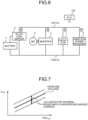
- a bus target voltage is set in such a manner as to reduce the power supplied from the wireless power receiver 4 to the battery 3.
- FIG. 6 is a view for describing a calculation method of a bus voltage prediction value. Note that a white arrow in FIG. 6 indicates a current flow direction.
- FIG. 7 is a graph illustrating a relationship between an SOC and a voltage of a capacitor 7 as a characteristic of the capacitor 7. In FIG. 7 , an SOC Cap is an SOC of the capacitor 7, and V Cap is a voltage of the capacitor 7.
- a PWM duty at the time of performing PWM control of rotational driving of the motor generator 2 is determined on the basis of the fluctuation of the power received by the wireless power receiver 4 from the wireless power transmitters 21 by the dynamic wireless power transfer.
- the PWM duty is calculated by, for example, the following Formula (1).
- the bus voltage prediction value in the above Formula (1) estimates the bus voltage from the characteristic of the capacitor 7 (relationship between the SOC and the voltage of the capacitor 7) as illustrated in FIG. 7 on the basis of a cyclic DWPT power instantaneous value. At this time, an instantaneous voltage of the capacitor 7 is estimated with a fluctuation component with respect to an open end voltage being included on the basis of input/output power (charged/discharged current) of the capacitor 7 and capacitor internal resistance.
- the power supplied to the capacitor 7 can be calculated by the following Formula (2).
- P Cap is the power input to the capacitor 7
- P DWPT is the DWPT power (power output from the wireless power receiver 4)
- P Inv(MG) is the power input to the inverter 5 (motor generator 2)
- P DCDC(Bat) is the power input to the DC-DC converter 6 (battery 3).
- an arrangement interval in the vehicle traveling direction of the plurality of wireless power transmitters 21 arranged on the road 22 on which the vehicle 1 is traveling is constant, it is possible to calculate a movement distance of the vehicle 1 from a current vehicle speed and to calculate a relative position of the vehicle 1 with respect to each of the plurality of wireless power transmitters 21.
- a fluctuation component (repetition) of the power received by the wireless power receiver 4 from the wireless power transmitters 21 by the dynamic wireless power transfer.
- the movement distance of the vehicle 1 is calculated from the current vehicle speed and the relative position of the vehicle 1 (wireless power receiver 4) with respect to each of the plurality of wireless power transmitters 21 is calculated, as a vehicle position of a starting point on the road 22, for example, the vehicle position detected at predetermined timing by utilization of a GPS of a car navigation system provided in the vehicle 1 may be set.
- the cycle of the fluctuation of the DWPT power (bus voltage) during the dynamic wireless power transfer at a predetermined vehicle speed may be estimated on the basis of a rotation angle of the motor generator 2 instead of the vehicle speed.
- FIG. 9 is a block diagram for describing a configuration of a vehicle 1 including two motor generators.
- the vehicle 1 illustrated in FIG. 9 includes a first motor generator (MG1) 2A, a second motor generator (MG2) 2B, a battery 3, a wireless power receiver 4, a first inverter 5A, a second inverter 5B, a DC-DC converter 6, a capacitor 7, a power bus 10, and an ECU 100.
- the wireless power receiver 4, the first inverter 5A, the second inverter 5B, the DC-DC converter 6, and the capacitor 7 are electrically connected to the power bus 10 in parallel.
- a positive electrode-side terminal of the battery 3 is electrically connected to the DC-DC converter and a negative electrode-side terminal thereof is electrically connected to a negative electrode side of the power bus 10, and the battery 3 is electrically connected to the power bus 10 via the DC-DC converter 6.
- the first motor generator 2A is electrically connected to the first inverter 5A.
- the second motor generator 2B is electrically connected to the second inverter 5B.
- the first motor generator 2A is connected to an engine (not illustrated) mounted on the vehicle 1 in such a manner that power can be transmitted, and is mainly used for power generation by driving force from the engine.
- the power generated by the first motor generator 2A can be supplied to the second motor generator 2B and the battery 3.
- the second motor generator 2B is mainly used for generating a driving force for traveling of the vehicle 1.
- both the first motor generator 2A and the DC-DC converter 6 compensate for a fluctuation component in the bus voltage which fluctuation component is caused by a power ripple in the dynamic wireless power transfer.
- the power generated by the first motor generator 2A also compensates for the fluctuation component of the bus voltage due to the power ripple.
- a torque command of the first motor generator 2A is varied according to the power fluctuation of the wireless power receiver 4, and this torque fluctuation is smoothed by inertia of the engine. As a result, it is possible to reduce the power output from the battery 3 to compensate for the fluctuation component, and thus, it is possible to further reduce the loss in the DC-DC converter 6.
Landscapes
- Engineering & Computer Science (AREA)
- Power Engineering (AREA)
- Transportation (AREA)
- Mechanical Engineering (AREA)
- Computer Networks & Wireless Communication (AREA)
- Electric Propulsion And Braking For Vehicles (AREA)
- Charge And Discharge Circuits For Batteries Or The Like (AREA)
- Current-Collector Devices For Electrically Propelled Vehicles (AREA)
Abstract
Description
- The present invention relates to a vehicle.
- Patent Literature 1 discloses a vehicle capable of supplying power, which is received by a wireless power receiver in a wireless manner from a plurality of wireless power transmitters installed on a traveling path by dynamic wireless power transfer, to a motor generator (inverter) and a battery that is a power supply via a DC-DC converter.
- Patent Literature 1:
Japanese Laid-open Patent Publication No. 2014-147160 - However, in the vehicle disclosed in Patent Literature 1, power transmission coils are discretely arranged, power is discretely fed according to a vehicle traveling position, and the power received by the wireless power receiver from the wireless power transmitters greatly fluctuates. Thus, a bus voltage of when power is supplied from the wireless power receiver to the motor generator (inverter) or the battery also greatly fluctuates, and deterioration due to charging and discharging of the battery is caused.
- The present invention has been made in view of the above problem, and an object thereof is to provide a vehicle capable of controlling deterioration of a power supply.
- To resolve the above problem and attain the object, a vehicle according to the present invention includes: a wireless power receiver that receives power in a wireless manner from a plurality of wireless power transmitters arranged at predetermined intervals in a vehicle traveling direction on a traveling path; a rotating electric machine capable of generating driving force for traveling; an inverter that exchanges power with the rotating electrical machine; a first power supply; a second power supply having higher output density and lower capacity density than the first power supply has; and a DC-DC converter that exchanges power with the first power supply. Further, the wireless power receiver, the inverter, the DC-DC converter, and the second power supply are electrically connected in parallel to a power bus that supplies power from the wireless power receiver to the inverter, and the first power supply and the power bus are electrically connected via the DC-DC converter.
- As a result, the DC-DC converter is provided between the first power supply and the power bus and charging and discharging of the first power supply due to fluctuation of the power received by the wireless power receiver from the wireless power transmitters can be controlled, whereby deterioration of the first power supply can be controlled.
- Further, in the above configuration, the wireless power receiver and the power bus may be electrically connected directly.
- As a result, it is possible to control a power loss of when the power is supplied from the wireless power receiver to the inverter through the power bus.
- Further, in the above configuration, the first power supply may be a secondary battery, and the second power supply may be a capacitor.
- As a result, components generally mounted on the vehicle can be used as the first power supply and the second power supply.
- Further, in the above configuration, a DC-DC conversion command value in the DC-DC converter may be set in such a manner that a desired bus average voltage according to required power of the rotating electric machine is acquired.
- As a result, the bus average voltage clamped by the second power supply can be adjusted by adjustment of an average charging/discharging amount of the first power supply.
- Further, in the above configuration, feedback control of the DC-DC conversion command value may be performed according to a difference between a target bus voltage and an actual bus voltage.
- As a result, control accuracy of the bus average voltage can be improved.
- Further, in the above configuration, in a case where the wireless power receiver is a current type, a bus voltage may be increased as power consumption of the rotating electric machine is larger.
- As a result, as the power consumption of the rotating electric machine is larger, the wireless power receiver can receive a larger amount of power from the wireless power transmitters by the dynamic wireless power transfer.
- Further, in the above configuration, in a case where the wireless power receiver is a voltage type, a bus voltage may be set according to power consumption of the rotating electric machine and average received power of the wireless power receiver.
- As a result, as the power consumption of the rotating electric machine is larger, the wireless power receiver can receive a larger amount of power from the wireless power transmitters by the dynamic wireless power transfer.
- Further, in the above configuration, a bus target voltage may be set in such a manner that the power supplied from the wireless power receiver to the first power supply is reduced in a case where a side of the wireless power receiver does not have a regeneration function of returning the power to a system side and the rotating electrical machine performs regenerative operation.
- As a result, even when the bus voltage increases due to regenerative power from the rotating electric machine, when the power supplied from the wireless power receiver to the first power supply is decreased, it is possible to prevent the power supplied from the rotating electric machine and the wireless power receiver to the first power supply from becoming too large and the first power supply from becoming likely to deteriorate.
- Further, in the above configuration, a PWM duty of when PWM control of rotational driving of the rotating electric machine is performed may be determined on a basis of a fluctuation of the power received by the wireless power receiver from the wireless power transmitters.
- As a result, even when the bus voltage fluctuates due to a power ripple in the dynamic wireless power transfer, accuracy of the PWM control can be secured.
- Further, in the above configuration, a bus voltage may be estimated on a basis of a vehicle position or a vehicle speed.
- As a result, since a distance between the wireless power transmitters adjacent in a vehicle traveling direction is constant, it is possible to calculate a movement distance of the vehicle from a current vehicle speed and to calculate a relative position of the vehicle with respect to each of the plurality of wireless power transmitters. Thus, on the basis of the above, it is possible to estimate a fluctuation component (repetition) of the power received by the wireless power receiver from the wireless power transmitters by the dynamic wireless power transfer.
- Further, in the above configuration, the vehicle may further include a rotating electric machine for power generation in addition to the rotating electric machine capable of generating the driving force for traveling. Further, both the rotating electric machine for power generation and the DC-DC converter compensate for a fluctuation component in a bus voltage which fluctuation component is caused by a power ripple.
- As a result, the loss in the DC-DC converter can be further reduced.
- The vehicle according to the present invention has an effect that deterioration of the first power supply can be controlled since the DC-DC converter is provided between the first power supply and the power bus and charging and discharging of the first power supply due to fluctuation of the power received by the wireless power receiver from the wireless power transmitters can be controlled.
-
-
FIG. 1 is a view schematically illustrating a vehicle according to an embodiment. -
FIG. 2 is a block diagram for describing a configuration of the vehicle. -
FIG. 3 is a view for describing a fluctuation in DWPT power. -
FIG. 4(a) is a graph illustrating a relationship between a DC link voltage and DWPT power in a current-type dynamic wireless power transfer system.FIG. 4(b) is a graph illustrating a relationship between the DC link voltage and an MG output. -
FIG. 5(a) is a graph illustrating a relationship between a DC link voltage and DWPT power in a voltage-type dynamic wireless power transfer system.FIG. 5(b) is a graph illustrating a relationship between the DC link voltage and the MG output. -
FIG. 6 is a view for describing a calculation method of a bus voltage prediction value. -
FIG. 7 is a graph illustrating a relationship between an SOC and a voltage of a capacitor as a characteristic of the capacitor. -
FIG. 8 is a view for describing a difference in a cycle of fluctuation of the DWPT power depending on a vehicle speed. -
FIG. 9 is a block diagram for describing a configuration of a vehicle including two motor generators. - Hereinafter, an embodiment of a vehicle according to the present invention will be described. Note that the present invention is not limited by the present embodiment.
-
FIG. 1 is a view schematically illustrating a vehicle 1 according to an embodiment. The vehicle 1 according to the embodiment is an electric vehicle equipped with amotor generator 2 as a power source for traveling. In the vehicle 1, for example, themotor generator 2 is driven when power stored in abattery 3 is supplied to themotor generator 2. Power output from themotor generator 2 is transmitted to driving wheels via a power transmission device. - In addition, the vehicle 1 according to the embodiment includes a
wireless power receiver 4 that can receive power, which is supplied from awireless power transmitter 21 having a power transmission coil and installed on aroad 22 that is a traveling path on which the vehicle 1 can travel, in a wireless manner by a power reception coil. Note that a dynamic wireless power transfer (DWPT) system in which power can be fed from thewireless power transmitter 21 to thewireless power receiver 4 in a wireless manner while the vehicle 1 is traveling includes thewireless power transmitter 21 and thewireless power receiver 4 in the present embodiment. Then, in the vehicle 1 according to the embodiment, the power received by thewireless power receiver 4 from thewireless power transmitter 21 by the dynamic wireless power transfer is supplied to themotor generator 2 and thebattery 3. -
FIG. 2 is a block diagram for describing a configuration of the vehicle 1. As illustrated inFIG. 2 , the vehicle 1 according to the embodiment includes themotor generator 2, thebattery 3, thewireless power receiver 4, aninverter 5, a DC-DC converter 6, acapacitor 7, apower bus 10, and an electronic control unit (ECU) 100. Thepower bus 10 includes a power bus for apositive electrode 10P and a power bus for anegative electrode 10N. Then, in the vehicle 1 according to the embodiment, thewireless power receiver 4, theinverter 5, the DC-DC converter 6, and thecapacitor 7 are arranged in parallel and electrically connected to thepower bus 10 between the power bus for apositive electrode 10P and the power bus for anegative electrode 10N. In addition, a positive electrode-side terminal of thebattery 3 is electrically connected to the DC-DC converter and a negative electrode-side terminal thereof is electrically connected to the power bus for anegative electrode 10N of thepower bus 10, and thebattery 3 is electrically connected to thepower bus 10 via the DC-DC converter 6. In addition, themotor generator 2 is electrically connected to theinverter 5 in such a manner that three-phase AC power can be transmitted and received. - The motor generator (MG) 2 is a rotating electrical machine having a function as an electric motor and a function as a generator. For example, when the vehicle 1 travels by the power of the
motor generator 2, theECU 100 that is an electronic control device controls theinverter 5, whereby torque output from themotor generator 2 is controlled. - The
battery 3 is a first power supply and is a secondary battery capable of storing power to be supplied to themotor generator 2. Note that a component generally mounted on the vehicle (electric vehicle) can be used, and for example, a lithium ion battery or the like can be used as the secondary battery. Thebattery 3 stores the power received by thewireless power receiver 4 and having a voltage adjusted by the DC-DC converter 6. In addition, thebattery 3 supplies power for generating vehicle driving force by themotor generator 2 to theinverter 5 via the DC-DC converter 6. Furthermore, thebattery 3 stores power generated by regenerative operation of themotor generator 2 via the DC-DC converter 6. - Note that although not illustrated, the
battery 3 is provided with a voltage sensor and a current sensor to detect a voltage of thebattery 3 and an input/output current. These detection values are output to theECU 100. TheECU 100 calculates a state of charge (SOC) of thebattery 3 on the basis of the voltage and the current detected by the voltage sensor and the current sensor. - The
wireless power receiver 4 includes the power reception coil capable of receiving power in a wireless manner from the power transmission coil of thewireless power transmitter 21 installed on theroad 22, for example, while the vehicle 1 is traveling. Then, for example, the power is transmitted from thewireless power transmitter 21 to thewireless power receiver 4 in a state in which thewireless power receiver 4 is located within a range of a predetermined distance from thewireless power transmitter 21. The power supplied from thewireless power transmitter 21 to thewireless power receiver 4 is transmitted to themotor generator 2, thebattery 3, and the like. - The
inverter 5 can exchange power with themotor generator 2, and converts DC power from thepower bus 10 into AC power and supplies the AC power to themotor generator 2, and converts AC power from themotor generator 2 into DC power and supplies the DC power to thepower bus 10. - The DC-
DC converter 6 adjusts a pressure of the power exchanged between thepower bus 10 and the battery 3 (power charged and discharged by the battery 3). - The
capacitor 7 is a second power supply having higher output density and lower capacity density than the first power supply (battery 3), and can temporarily store a part of the power supplied from thewireless power receiver 4 to thepower bus 10. As thecapacitor 7, a component generally mounted on the vehicle (electric vehicle) can be used, and, for example, an electrical double layer capacitor (EDLC), a lithium ion capacitor (LIC), a super redox capacitor (SRC), and the like can be used. - Here, as illustrated in
FIG. 1 , a plurality of thewireless power transmitters 21 is discretely arranged on theroad 22 in a vehicle traveling direction. In the dynamic wireless power transfer system, in a case where wireless power transfer from thewireless power transmitters 21 installed on theroad 22 to thewireless power receiver 4 provided in the vehicle 1 during traveling of the vehicle 1 (dynamic wireless power transfer) is performed, as illustrated inFIG. 3 , unlike pantograph power transfer of a contact power transfer system, DWPT power (PDWPT) that is power supplied from thewireless power transmitters 21 to thewireless power receiver 4 greatly fluctuates. In other words, a large power ripple is generated in the DWPT power received by thewireless power receiver 4. Thus, a bus voltage that is a voltage of thepower bus 10 of when the power is supplied from thewireless power receiver 4 to the motor generator 2 (inverter 5) and the battery 3 (DC-DC converter 6) also greatly fluctuates, and deterioration of thebattery 3 and deterioration of controllability of themotor generator 2 are caused. In the dynamic wireless power transfer, the cause of the fluctuation of the power received by thewireless power receiver 4 from thewireless power transmitters 21 is, for example, that the power is discretely fed from the plurality ofwireless power transmitters 21 discretely arranged on theroad 22 in the vehicle traveling direction, or that the power is fed while relative positions of thewireless power transmitters 21 and thewireless power receiver 4 change due to a positional deviation in a left and right direction. - Thus, in the vehicle 1 according to the embodiment, a bus having a large voltage fluctuation is connected to the
battery 3 via the DC-DC converter 6, the converted power by the DC-DC converter 6 is leveled (mainly, a DC component is converted), and the input/output power ripple of thebattery 3 is controlled, whereby the deterioration of thebattery 3 can be controlled. Thecapacitor 7 is charged and discharged for power of a difference between the received power having a large fluctuation from thewireless power receiver 4 and leveled power exchanged with thebattery 3 via the DC-DC converter 6, and the bus voltage also fluctuates according to the power fluctuation. A method of controlling deterioration of motor generator control which deterioration is caused by the bus voltage fluctuation will be described later. - In addition, in the vehicle 1 according to the embodiment, since the power is fed from the
wireless power receiver 4 to theinverter 5 directly without the DC-DC converter 6, a power loss can be reduced as compared with a case where the power is supplied from thewireless power receiver 4 to theinverter 5 via the DC-DC converter 6. - In addition, in the vehicle 1 according to the embodiment, the DC-
DC converter 6 is provided between thebattery 3 and thepower bus 10, and it is possible to control charging and discharging of thebattery 3 due to fluctuation of the power received by thewireless power receiver 4 from thewireless power transmitters 21. Thus, it is possible to reduce the capacity of thebattery 3. Note that it is possible to reduce the loss by using, as the DC-DC converter 6, a small-capacity DC-DC converter for conversion of the power charged and discharged by thebattery 3. - In addition, in the vehicle 1 according to the embodiment, the
wireless power receiver 4 and thepower bus 10 are directly connected without the DC-DC converter 6 being connected between thewireless power receiver 4 and thepower bus 10. As a result, in the vehicle 1 according to the embodiment, since the power is supplied from thewireless power receiver 4 to the motor generator 2 (inverter 5) through thepower bus 10 without passing through the DC-DC converter 6, the power loss in the DC-DC converter 6 can be reduced as compared with a case where the DC-DC converter 6 is connected between thewireless power receiver 4 and thepower bus 10 and the power is supplied from thewireless power receiver 4 to both the motor generator 2 (inverter 5) and thebattery 3 through thepower bus 10 via the DC-DC converter 6. - In addition, in the vehicle 1 according to the embodiment, a DC-DC conversion command value in the DC-
DC converter 6 is set in such a manner as to acquire a desired bus average voltage according to MG power (required power of themotor generator 2 in the dynamic wireless power transfer system). In other words, the DC-DC conversion command value is set according to the MG power command value and a battery charging/discharging power command value. As a result, in the vehicle 1 according to the embodiment, the bus average voltage clamped by thecapacitor 7 can be adjusted by an adjustment of the battery charging/discharging average amount. - In the vehicle 1 according to the embodiment, the bus voltage of the
power bus 10 is controlled according to the DC link voltage and the received power of thewireless power receiver 4 in the dynamic wireless power transfer system is controlled. For example, in the vehicle 1 according to the embodiment, feedback-control of the DC-DC converter conversion command value is performed according to a difference between the target bus voltage and the actual bus voltage. As a result, control accuracy of the bus average voltage can be improved. -
FIG. 4(a) is a graph illustrating a relationship between a DC link voltage and DWPT power in a current-type dynamic wireless power transfer system.FIG. 4(b) is a graph illustrating a relationship between the DC link voltage and an MG output. - In a case where the current type (such as immittance or SS) is adopted as the
wireless power receiver 4 included in the dynamic wireless power transfer system, as illustrated inFIG. 4(a) , a relationship in which the DWPT power increases as the DC link voltage increases is satisfied. In addition, in the DC link voltage, as illustrated inFIG. 4(b) , the required DC link voltage increases as the MG output (power consumption of the motor generator 2) increases. Thus, in the vehicle 1 according to the embodiment, in a case where thewireless power receiver 4 is the current type, the DWPT power is increased in order to increase the DC link voltage (bus voltage) as the MG output is larger. As a result, as the power consumption of themotor generator 2 becomes larger, thewireless power receiver 4 can receive a larger amount of power from thewireless power transmitters 21 by the dynamic wireless power transfer. -
FIG. 5(a) is a graph illustrating a relationship between a DC link voltage and DWPT power in a voltage-type dynamic wireless power transfer system.FIG. 5(b) is a graph illustrating a relationship between the DC link voltage and an MG output. - In a case where the voltage type (such as BPF or PP) is adopted for the
wireless power receiver 4 included in the dynamic wireless power transfer system, as illustrated inFIG. 5(a) , the average received power of thewireless power receiver 4 decreases as the DC link voltage (bus voltage) increases. Thus, the DC link voltage (bus voltage) at which the MG output (power consumption of the motor generator 2) illustrated inFIG. 5(b) and the average received power can be balanced is set. As a result, as the power consumption of themotor generator 2 becomes larger, thewireless power receiver 4 can receive a larger amount of power from thewireless power transmitters 21 by the dynamic wireless power transfer. - In addition, in the vehicle 1 according to the embodiment, in a case where the dynamic wireless power transfer system side has no regeneration function of returning power to a system side and the
motor generator 2 performs the regenerative operation, a bus target voltage is set in such a manner as to reduce the power supplied from thewireless power receiver 4 to thebattery 3. As a result, even when the bus voltage increases due to regenerative power from themotor generator 2, since the power supplied from thewireless power receiver 4 to thebattery 3 is reduced, it is possible to prevent the power supplied from themotor generator 2 and thewireless power receiver 4 to thebattery 3 from becoming too large and thebattery 3 from being easily deteriorated. -
FIG. 6 is a view for describing a calculation method of a bus voltage prediction value. Note that a white arrow inFIG. 6 indicates a current flow direction.FIG. 7 is a graph illustrating a relationship between an SOC and a voltage of acapacitor 7 as a characteristic of thecapacitor 7. InFIG. 7 , an SOCCap is an SOC of thecapacitor 7, and VCap is a voltage of thecapacitor 7. - In addition, in the vehicle 1 according to the embodiment, a PWM duty at the time of performing PWM control of rotational driving of the
motor generator 2 is determined on the basis of the fluctuation of the power received by thewireless power receiver 4 from thewireless power transmitters 21 by the dynamic wireless power transfer. The PWM duty is calculated by, for example, the following Formula (1). - Formula (1)

- The bus voltage prediction value in the above Formula (1) estimates the bus voltage from the characteristic of the capacitor 7 (relationship between the SOC and the voltage of the capacitor 7) as illustrated in
FIG. 7 on the basis of a cyclic DWPT power instantaneous value. At this time, an instantaneous voltage of thecapacitor 7 is estimated with a fluctuation component with respect to an open end voltage being included on the basis of input/output power (charged/discharged current) of thecapacitor 7 and capacitor internal resistance. - In a case where the power is supplied from the
wireless power receiver 4 to the inverter 5 (motor generator 2) and the DC-DC converter 6 (battery 3), the power supplied to thecapacitor 7 can be calculated by the following Formula (2). Note that in the following Formula (2), PCap is the power input to thecapacitor 7, PDWPT is the DWPT power (power output from the wireless power receiver 4), PInv(MG) is the power input to the inverter 5 (motor generator 2), and PDCDC(Bat) is the power input to the DC-DC converter 6 (battery 3). - Formula (2)

- In the vehicle 1 according to the embodiment, by performing the PWM control of the rotational driving of the
motor generator 2 by using the PWM duty calculated by the above Formula (1), it is possible to secure the accuracy of the PWM control even when the bus voltage fluctuates due to the power ripple in the dynamic wireless power transfer. - In addition, in the present embodiment, since an arrangement interval in the vehicle traveling direction of the plurality of
wireless power transmitters 21 arranged on theroad 22 on which the vehicle 1 is traveling (distance between thewireless power transmitters 21 adjacent in the vehicle traveling direction) is constant, it is possible to calculate a movement distance of the vehicle 1 from a current vehicle speed and to calculate a relative position of the vehicle 1 with respect to each of the plurality ofwireless power transmitters 21. Thus, on the basis of the relative position of the vehicle 1 (wireless power receiver 4) with respect to thewireless power transmitters 21, it is possible to estimate a fluctuation component (repetition) of the power received by thewireless power receiver 4 from thewireless power transmitters 21 by the dynamic wireless power transfer. - For example, as illustrated in
FIG. 8 , in a case where the DWPT power (bus voltage) fluctuates during the dynamic wireless power transfer at a predetermined vehicle speed in a cycle Tl, when the vehicle speed decreases to a constant vehicle speed at time t1, the cycle of the fluctuation of the DWPT power (bus voltage) becomes a cycle T2 longer than the cycle T1. Thus, in the vehicle 1 according to the embodiment, it is possible to estimate the DWPT power and thus the bus voltage on the basis of the vehicle position (vehicle speed) on theroad 22 when performing the dynamic wireless power transfer. - Note that when the movement distance of the vehicle 1 is calculated from the current vehicle speed and the relative position of the vehicle 1 (wireless power receiver 4) with respect to each of the plurality of
wireless power transmitters 21 is calculated, as a vehicle position of a starting point on theroad 22, for example, the vehicle position detected at predetermined timing by utilization of a GPS of a car navigation system provided in the vehicle 1 may be set. In addition, the cycle of the fluctuation of the DWPT power (bus voltage) during the dynamic wireless power transfer at a predetermined vehicle speed may be estimated on the basis of a rotation angle of themotor generator 2 instead of the vehicle speed. -
FIG. 9 is a block diagram for describing a configuration of a vehicle 1 including two motor generators. The vehicle 1 illustrated inFIG. 9 includes a first motor generator (MG1) 2A, a second motor generator (MG2) 2B, abattery 3, awireless power receiver 4, afirst inverter 5A, asecond inverter 5B, a DC-DC converter 6, acapacitor 7, apower bus 10, and anECU 100. In addition, in the vehicle 1 illustrated inFIG. 9 , thewireless power receiver 4, thefirst inverter 5A, thesecond inverter 5B, the DC-DC converter 6, and thecapacitor 7 are electrically connected to thepower bus 10 in parallel. In addition, a positive electrode-side terminal of thebattery 3 is electrically connected to the DC-DC converter and a negative electrode-side terminal thereof is electrically connected to a negative electrode side of thepower bus 10, and thebattery 3 is electrically connected to thepower bus 10 via the DC-DC converter 6. Thefirst motor generator 2A is electrically connected to thefirst inverter 5A. Thesecond motor generator 2B is electrically connected to thesecond inverter 5B. - In the vehicle 1 illustrated in
FIG. 9 , thefirst motor generator 2A is connected to an engine (not illustrated) mounted on the vehicle 1 in such a manner that power can be transmitted, and is mainly used for power generation by driving force from the engine. The power generated by thefirst motor generator 2A can be supplied to thesecond motor generator 2B and thebattery 3. In addition, in the vehicle 1 illustrated inFIG. 9 , thesecond motor generator 2B is mainly used for generating a driving force for traveling of the vehicle 1. - In the vehicle 1 according to the embodiment, as illustrated in
FIG. 9 , in a case where two motor generators that are thefirst motor generator 2A mainly for power generation and thesecond motor generator 2B mainly for driving force generation are provided, both thefirst motor generator 2A and the DC-DC converter 6 compensate for a fluctuation component in the bus voltage which fluctuation component is caused by a power ripple in the dynamic wireless power transfer. As a result, in a case where the engine is driven and the power generated by thefirst motor generator 2A is supplied to thesecond motor generator 2B while the power is received by thewireless power receiver 4 by the dynamic wireless power transfer (in a case where a request for torque and an output of thesecond motor generator 2B is large), the power generated by thefirst motor generator 2A also compensates for the fluctuation component of the bus voltage due to the power ripple. Specifically, a torque command of thefirst motor generator 2A is varied according to the power fluctuation of thewireless power receiver 4, and this torque fluctuation is smoothed by inertia of the engine. As a result, it is possible to reduce the power output from thebattery 3 to compensate for the fluctuation component, and thus, it is possible to further reduce the loss in the DC-DC converter 6. - According to the present invention, it is possible to provide a vehicle capable of controlling deterioration of a power supply.
-
- 1 VEHICLE
- 2 MOTOR GENERATOR
- 2A FIRST MOTOR GENERATOR
- 2B SECOND MOTOR GENERATOR
- 3 BATTERY
- 4 WIRELESS POWER RECEIVER
- 5 INVERTER
- 5A FIRST INVERTER
- 5B SECOND INVERTER
- 6 DC-DC CONVERTER
- 7 CAPACITOR
- 10 POWER BUS
- 100 ECU
Claims (11)
- A vehicle comprising:a wireless power receiver that receives power in a wireless manner from a plurality of wireless power transmitters arranged at predetermined intervals in a vehicle traveling direction on a traveling path;a rotating electric machine capable of generating driving force for traveling;an inverter that exchanges power with the rotating electrical machine;a first power supply;a second power supply having higher output density and lower capacity density than the first power supply has; anda DC-DC converter that exchanges power with the first power supply, whereinthe wireless power receiver, the inverter, the DC-DC converter, and the second power supply are electrically connected in parallel to a power bus that supplies power from the wireless power receiver to the inverter, andthe first power supply and the power bus are electrically connected via the DC-DC converter.
- The vehicle according to claim 1, wherein the wireless power receiver and the power bus are electrically connected directly.
- The vehicle according to claim 1 or 2, whereinthe first power supply is a secondary battery, andthe second power supply is a capacitor.
- The vehicle according to any one of claims 1 to 3, wherein a DC-DC conversion command value in the DC-DC converter is set in such a manner that a desired bus average voltage according to required power of the rotating electric machine is acquired.
- The vehicle according to claim 4, wherein feedback control of the DC-DC conversion command value is performed according to a difference between a target bus voltage and an actual bus voltage.
- The vehicle according to any one of claims 1 to 5, wherein in a case where the wireless power receiver is a current type, a bus voltage is increased as power consumption of the rotating electric machine is larger.
- The vehicle according to any one of claims 1 to 5, wherein in a case where the wireless power receiver is a voltage type, a bus voltage is set according to power consumption of the rotating electric machine and average received power of the wireless power receiver.
- The vehicle according to claim 6 or 7, wherein a bus target voltage is set in such a manner that the power supplied from the wireless power receiver to the first power supply is reduced in a case where a side of the wireless power receiver does not have a regeneration function of returning the power to a system side and the rotating electrical machine performs regenerative operation.
- The vehicle according to any one of claims 1 to 8, wherein a PWM duty of when PWM control of rotational driving of the rotating electric machine is performed is determined on a basis of a fluctuation of the power received by the wireless power receiver from the wireless power transmitters.
- The vehicle according to claim 9, wherein bus voltage is estimated on a basis of a vehicle position or a vehicle speed.
- The vehicle according to any one of claims 1 to 10, further comprisinga rotating electric machine for power generation in addition to the rotating electric machine capable of generating the driving force for traveling, whereinboth the rotating electric machine for power generation and the DC-DC converter compensate for a fluctuation component in a bus voltage which fluctuation component is caused by a power ripple.
Applications Claiming Priority (2)
| Application Number | Priority Date | Filing Date | Title |
|---|---|---|---|
| JP2022009662A JP2023108505A (en) | 2022-01-25 | 2022-01-25 | vehicle |
| PCT/JP2022/043773 WO2023145232A1 (en) | 2022-01-25 | 2022-11-28 | Vehicle |
Publications (2)
| Publication Number | Publication Date |
|---|---|
| EP4470829A1 true EP4470829A1 (en) | 2024-12-04 |
| EP4470829A4 EP4470829A4 (en) | 2025-09-17 |
Family
ID=87471426
Family Applications (1)
| Application Number | Title | Priority Date | Filing Date |
|---|---|---|---|
| EP22924084.1A Pending EP4470829A4 (en) | 2022-01-25 | 2022-11-28 | VEHICLE |
Country Status (4)
| Country | Link |
|---|---|
| EP (1) | EP4470829A4 (en) |
| JP (1) | JP2023108505A (en) |
| CN (1) | CN118613392A (en) |
| WO (1) | WO2023145232A1 (en) |
Family Cites Families (10)
| Publication number | Priority date | Publication date | Assignee | Title |
|---|---|---|---|---|
| JP4379441B2 (en) * | 2006-07-18 | 2009-12-09 | トヨタ自動車株式会社 | Power supply system, vehicle equipped with the same, power storage device temperature rise control method, and computer-readable recording medium storing a program for causing a computer to execute power storage device temperature rise control |
| JP2011062037A (en) * | 2009-09-14 | 2011-03-24 | Kawasaki Heavy Ind Ltd | Contactless charging system |
| CN103222148B (en) * | 2011-09-13 | 2014-06-18 | 丰田自动车株式会社 | Vehicle battery system and method for controlling same |
| JP6164853B2 (en) * | 2013-01-28 | 2017-07-19 | 株式会社テクノバ | Non-contact power supply system while traveling |
| US9634514B2 (en) * | 2014-05-30 | 2017-04-25 | Infineon Technologies Austria Ag | Single stage rectification and regulation for wireless charging systems |
| JP6798123B2 (en) * | 2016-03-22 | 2020-12-09 | 株式会社Ihi | Power transmission equipment and contactless power supply system |
| WO2018061400A1 (en) * | 2016-09-30 | 2018-04-05 | 株式会社日立製作所 | Combined power storage system |
| US10981557B2 (en) * | 2019-01-11 | 2021-04-20 | GM Global Technology Operations LLC | Battery pack balancing systems and control logic for multi-pack electric-drive motor vehicles |
| JP7243450B2 (en) * | 2019-05-27 | 2023-03-22 | 株式会社デンソー | Power supply system while driving |
| CN113629891B (en) * | 2021-08-17 | 2023-04-28 | 西南交通大学 | Efficiency optimization method for dynamic wireless power supply system of electric automobile |
-
2022
- 2022-01-25 JP JP2022009662A patent/JP2023108505A/en active Pending
- 2022-11-28 CN CN202280089902.XA patent/CN118613392A/en active Pending
- 2022-11-28 WO PCT/JP2022/043773 patent/WO2023145232A1/en not_active Ceased
- 2022-11-28 EP EP22924084.1A patent/EP4470829A4/en active Pending
Also Published As
| Publication number | Publication date |
|---|---|
| CN118613392A (en) | 2024-09-06 |
| WO2023145232A1 (en) | 2023-08-03 |
| EP4470829A4 (en) | 2025-09-17 |
| JP2023108505A (en) | 2023-08-04 |
Similar Documents
| Publication | Publication Date | Title |
|---|---|---|
| EP1639696B1 (en) | Power supply apparatus, motor drive control method using the same and motor vehicle having the same mounted thereon | |
| JP4706648B2 (en) | Electric vehicle, charging state estimation method, and computer-readable recording medium recording a program for causing a computer to execute the charging state estimation method | |
| US8035252B2 (en) | Power supply system, vehicle with the same, temperature increase control method for power storage device and computer-readable recording medium bearing program for causing computer to execute temperature increase control of power storage device | |
| US11196103B2 (en) | Secondary battery system and method for controlling secondary battery | |
| JP5454987B2 (en) | Fuel cell system | |
| US20100026237A1 (en) | Motored vehicle and method of controlling voltage conversion device | |
| US10079565B2 (en) | Electrically-driven vehicle | |
| US20120049774A1 (en) | Control device for voltage converter, vehicle equipped with the same, and control method for voltage converter | |
| US11070156B2 (en) | Power system | |
| US20110068740A1 (en) | Power supply system for vehicle, electric vehicle having the same, and method of controlling power supply system for vehicle | |
| US20070108936A1 (en) | Motor drive apparatus | |
| JP2010115048A (en) | Power supply system and electric power balance control method therefor | |
| WO2018061400A1 (en) | Combined power storage system | |
| JP2013060073A (en) | In-vehicle electric power generating device | |
| JP2011073611A (en) | Control device of hybrid vehicle | |
| JP5411237B2 (en) | Control device for hybrid vehicle | |
| US9738175B2 (en) | Drive device, transport apparatus, and energy storage control method | |
| EP4470829A1 (en) | Vehicle | |
| JP5949264B2 (en) | POWER SUPPLY DEVICE, VEHICLE EQUIPPED WITH THE SAME, AND METHOD FOR CONTROLLING POWER SUPPLY DEVICE | |
| EP4470828A1 (en) | Vehicle and power source for moving body | |
| JP5115444B2 (en) | Electric vehicle and control method thereof | |
| JP2014093883A (en) | Motive power output device | |
| CN115871481B (en) | Motor generator control system and hybrid vehicle | |
| JP6495412B1 (en) | Power system | |
| JP2010136574A (en) | Power supply system and vehicle equipped with it, and control method of power supply system |
Legal Events
| Date | Code | Title | Description |
|---|---|---|---|
| STAA | Information on the status of an ep patent application or granted ep patent |
Free format text: STATUS: THE INTERNATIONAL PUBLICATION HAS BEEN MADE |
|
| PUAI | Public reference made under article 153(3) epc to a published international application that has entered the european phase |
Free format text: ORIGINAL CODE: 0009012 |
|
| STAA | Information on the status of an ep patent application or granted ep patent |
Free format text: STATUS: REQUEST FOR EXAMINATION WAS MADE |
|
| 17P | Request for examination filed |
Effective date: 20240628 |
|
| AK | Designated contracting states |
Kind code of ref document: A1 Designated state(s): AL AT BE BG CH CY CZ DE DK EE ES FI FR GB GR HR HU IE IS IT LI LT LU LV MC ME MK MT NL NO PL PT RO RS SE SI SK SM TR |
|
| DAV | Request for validation of the european patent (deleted) | ||
| DAX | Request for extension of the european patent (deleted) | ||
| RIC1 | Information provided on ipc code assigned before grant |
Ipc: H02M 7/5387 20070101ALI20250521BHEP Ipc: H02M 3/335 20060101ALI20250521BHEP Ipc: H02J 50/10 20160101ALI20250521BHEP Ipc: H02J 7/00 20060101ALI20250521BHEP Ipc: B60M 7/00 20060101ALI20250521BHEP Ipc: B60L 53/12 20190101ALI20250521BHEP Ipc: B60L 5/00 20060101ALI20250521BHEP Ipc: B60L 3/00 20190101ALI20250521BHEP Ipc: B60L 58/20 20190101AFI20250521BHEP |
|
| RIC1 | Information provided on ipc code assigned before grant |
Ipc: H02M 7/5387 20070101ALI20250528BHEP Ipc: H02M 3/335 20060101ALI20250528BHEP Ipc: H02J 50/10 20160101ALI20250528BHEP Ipc: H02J 7/00 20060101ALI20250528BHEP Ipc: B60M 7/00 20060101ALI20250528BHEP Ipc: B60L 53/12 20190101ALI20250528BHEP Ipc: B60L 5/00 20060101ALI20250528BHEP Ipc: B60L 3/00 20190101ALI20250528BHEP Ipc: B60L 58/20 20190101AFI20250528BHEP |
|
| RAP1 | Party data changed (applicant data changed or rights of an application transferred) |
Owner name: DENSO CORPORATION |
|
| STAA | Information on the status of an ep patent application or granted ep patent |
Free format text: STATUS: EXAMINATION IS IN PROGRESS |
|
| A4 | Supplementary search report drawn up and despatched |
Effective date: 20250820 |
|
| RIC1 | Information provided on ipc code assigned before grant |
Ipc: B60L 58/20 20190101AFI20250813BHEP Ipc: B60L 3/00 20190101ALI20250813BHEP Ipc: B60L 5/00 20060101ALI20250813BHEP Ipc: B60L 53/12 20190101ALI20250813BHEP Ipc: B60M 7/00 20060101ALI20250813BHEP Ipc: H02J 7/00 20060101ALI20250813BHEP Ipc: H02J 50/10 20160101ALI20250813BHEP Ipc: H02M 3/335 20060101ALI20250813BHEP Ipc: H02M 7/5387 20070101ALI20250813BHEP |
|
| 17Q | First examination report despatched |
Effective date: 20250829 |