EP4470634A1 - Golf ball - Google Patents
Golf ball Download PDFInfo
- Publication number
- EP4470634A1 EP4470634A1 EP24173137.1A EP24173137A EP4470634A1 EP 4470634 A1 EP4470634 A1 EP 4470634A1 EP 24173137 A EP24173137 A EP 24173137A EP 4470634 A1 EP4470634 A1 EP 4470634A1
- Authority
- EP
- European Patent Office
- Prior art keywords
- hardness
- golf ball
- shore
- spherical core
- intermediate layer
- Prior art date
- Legal status (The legal status is an assumption and is not a legal conclusion. Google has not performed a legal analysis and makes no representation as to the accuracy of the status listed.)
- Granted
Links
Images

Classifications
-
- A—HUMAN NECESSITIES
- A63—SPORTS; GAMES; AMUSEMENTS
- A63B—APPARATUS FOR PHYSICAL TRAINING, GYMNASTICS, SWIMMING, CLIMBING, OR FENCING; BALL GAMES; TRAINING EQUIPMENT
- A63B37/00—Solid balls; Rigid hollow balls; Marbles
- A63B37/0003—Golf balls
- A63B37/007—Characteristics of the ball as a whole
- A63B37/0077—Physical properties
- A63B37/0092—Hardness distribution amongst different ball layers
- A63B37/00921—Hardness distribution amongst different ball layers whereby hardness of the cover is higher than hardness of the intermediate layers
-
- A—HUMAN NECESSITIES
- A63—SPORTS; GAMES; AMUSEMENTS
- A63B—APPARATUS FOR PHYSICAL TRAINING, GYMNASTICS, SWIMMING, CLIMBING, OR FENCING; BALL GAMES; TRAINING EQUIPMENT
- A63B37/00—Solid balls; Rigid hollow balls; Marbles
- A63B37/0003—Golf balls
- A63B37/0004—Surface depressions or protrusions
- A63B37/0017—Specified total dimple volume
-
- A—HUMAN NECESSITIES
- A63—SPORTS; GAMES; AMUSEMENTS
- A63B—APPARATUS FOR PHYSICAL TRAINING, GYMNASTICS, SWIMMING, CLIMBING, OR FENCING; BALL GAMES; TRAINING EQUIPMENT
- A63B37/00—Solid balls; Rigid hollow balls; Marbles
- A63B37/0003—Golf balls
- A63B37/0023—Covers
- A63B37/0029—Physical properties
- A63B37/0031—Hardness
-
- A—HUMAN NECESSITIES
- A63—SPORTS; GAMES; AMUSEMENTS
- A63B—APPARATUS FOR PHYSICAL TRAINING, GYMNASTICS, SWIMMING, CLIMBING, OR FENCING; BALL GAMES; TRAINING EQUIPMENT
- A63B37/00—Solid balls; Rigid hollow balls; Marbles
- A63B37/0003—Golf balls
- A63B37/0023—Covers
- A63B37/0029—Physical properties
- A63B37/0033—Thickness
-
- A—HUMAN NECESSITIES
- A63—SPORTS; GAMES; AMUSEMENTS
- A63B—APPARATUS FOR PHYSICAL TRAINING, GYMNASTICS, SWIMMING, CLIMBING, OR FENCING; BALL GAMES; TRAINING EQUIPMENT
- A63B37/00—Solid balls; Rigid hollow balls; Marbles
- A63B37/0003—Golf balls
- A63B37/0038—Intermediate layers, e.g. inner cover, outer core, mantle
- A63B37/004—Physical properties
- A63B37/0043—Hardness
-
- A—HUMAN NECESSITIES
- A63—SPORTS; GAMES; AMUSEMENTS
- A63B—APPARATUS FOR PHYSICAL TRAINING, GYMNASTICS, SWIMMING, CLIMBING, OR FENCING; BALL GAMES; TRAINING EQUIPMENT
- A63B37/00—Solid balls; Rigid hollow balls; Marbles
- A63B37/0003—Golf balls
- A63B37/0038—Intermediate layers, e.g. inner cover, outer core, mantle
- A63B37/004—Physical properties
- A63B37/0045—Thickness
-
- A—HUMAN NECESSITIES
- A63—SPORTS; GAMES; AMUSEMENTS
- A63B—APPARATUS FOR PHYSICAL TRAINING, GYMNASTICS, SWIMMING, CLIMBING, OR FENCING; BALL GAMES; TRAINING EQUIPMENT
- A63B37/00—Solid balls; Rigid hollow balls; Marbles
- A63B37/0003—Golf balls
- A63B37/005—Cores
- A63B37/006—Physical properties
- A63B37/0062—Hardness
- A63B37/00621—Centre hardness
-
- A—HUMAN NECESSITIES
- A63—SPORTS; GAMES; AMUSEMENTS
- A63B—APPARATUS FOR PHYSICAL TRAINING, GYMNASTICS, SWIMMING, CLIMBING, OR FENCING; BALL GAMES; TRAINING EQUIPMENT
- A63B37/00—Solid balls; Rigid hollow balls; Marbles
- A63B37/0003—Golf balls
- A63B37/005—Cores
- A63B37/006—Physical properties
- A63B37/0062—Hardness
- A63B37/00622—Surface hardness
-
- A—HUMAN NECESSITIES
- A63—SPORTS; GAMES; AMUSEMENTS
- A63B—APPARATUS FOR PHYSICAL TRAINING, GYMNASTICS, SWIMMING, CLIMBING, OR FENCING; BALL GAMES; TRAINING EQUIPMENT
- A63B37/00—Solid balls; Rigid hollow balls; Marbles
- A63B37/0003—Golf balls
- A63B37/007—Characteristics of the ball as a whole
- A63B37/0072—Characteristics of the ball as a whole with a specified number of layers
- A63B37/0075—Three piece balls, i.e. cover, intermediate layer and core
-
- A—HUMAN NECESSITIES
- A63—SPORTS; GAMES; AMUSEMENTS
- A63B—APPARATUS FOR PHYSICAL TRAINING, GYMNASTICS, SWIMMING, CLIMBING, OR FENCING; BALL GAMES; TRAINING EQUIPMENT
- A63B37/00—Solid balls; Rigid hollow balls; Marbles
- A63B37/0003—Golf balls
- A63B37/007—Characteristics of the ball as a whole
- A63B37/0077—Physical properties
- A63B37/0092—Hardness distribution amongst different ball layers
Definitions
- the volume of the dimple is the sum of the upper volume and the lower volume.
- the “total volume V of the dimples” in the present disclosure is the sum of the volume of all the dimples.
- the “total upper volume Vo of the dimples” is the sum of the upper volume of all the dimples.
- the “total lower volume Vi of the dimples” is the sum of the lower volume of all the dimples.
- a double ended arrow Dp2 indicates a second depth of the dimple 10.
- the second depth Dp2 is the distance between the deepest part of the dimple 10 and the tangent line Tg.
- the second depth Dp2 is preferably 0.08 mm or more, more preferably 0.10 mm or more, and even more preferably 0.12 mm or more, and is preferably 0.30 mm or less, more preferably 0.28 mm or less, and even more preferably 0.26 mm or less. If the second depth Dp2 is 0.08 mm or more, the dimples easily contribute to the turbulent air flow, and if the second depth Dp2 is 0.30 mm or less, the lift force obtained by the dimples is not excessively great, and the flight distance performance on a driver shot is better.
- the area of the dimple A is 15.21 mm 2
- the area of the dimple B is 14.42 mm 2
- the area of the dimple C is 13.53 mm 2
- the area of the dimple D is 11.79 mm 2
- the area of the dimple E is 7.07 mm 2 .
- the ratio (total areas of dimples/surface area of virtual sphere) of the sum of the areas A of all the dimples 10 to the surface area of the virtual sphere 14 is referred to as an occupation ratio So.
- the occupation ratio So is preferably 70% or more, more preferably 75% or more, and even more preferably 80% or more, and is preferably 95% or less, more preferably 92% or less, and even more preferably 90% or less. If the occupation ratio So falls within the above range, the effect of the turbulence by the dimples is greater.
- the number of the dimples can be appropriately adjusted depending on the diameter or occupation ratio of the dimples. It is noted that from the viewpoint of the occupation ratio or the function of the respective dimple, the total number of the dimples 10 is preferably 250 or more, more preferably 280 or more, and even more preferably 300 or more, and is preferably 450 or less, more preferably 410 or less, and even more preferably 390 or less.
- the golf ball according to the present disclosure satisfies (Hc/Tc) ⁇ (S ⁇ Hm/Vi) ⁇ 130.
- S is the hardness difference between the surface hardness Hs and the center hardness Ho of the spherical core
- Hm is the material hardness of the intermediate layer
- Hc is the material hardness of the outermost cover
- Tc is the thickness of the outermost cover
- Vi is the total lower volume of the dimples.
- the value (Hc/Tc) ⁇ (S ⁇ Hm/Vi) is preferably 55 or more, more preferably 57 or more, and even more preferably 60 or more, and is preferably 130 or less, more preferably 125 or less, and even more preferably 120 or less. If the value (Hc/Tc) ⁇ (S ⁇ Hm/Vi) falls within the above range, the difference in the flight distance on a driver shot between hit at a high head speed and hit at a low head speed is small.
- the value (Hm/Vi) is preferably 0.08 or more, more preferably 0.09 or more, and even more preferably 0.10 or more, and is preferably 0.22 or less, more preferably 0.20 or less, and even more preferably 0.18 or less. If the value (Hm/Vi) falls within the above range, lowering in the spin rate on a driver shot and the turbulent air flow by the dimples fully occur, and thus the flight distance performance is better.
- the golf ball according to the present disclosure preferably satisfies the surface hardness Hs (Shore C hardness) of the spherical core ⁇ the surface hardness Hms (Shore C hardness) of the intermediate layer > the surface hardness Hcs (Shore C hardness) of the golf ball.
- the difference (Hms-Hcs) between the surface hardness Hms of the intermediate layer and the surface hardness Hcs of the golf ball is preferably more than 0, more preferably 2 or more, and even more preferably 4 or more in Shore C hardness. If the difference (Hms-Hcs) is more than 0, the spin performance on an approach shot is better since the deformation of the cover when the golf ball is hit is greater. It is noted that the upper limit of the difference (Hms-Hcs) is not particularly limited, but it is about 20 in Shore C hardness.
- the difference (Hms-Hs) between the surface hardness Hms of the intermediate layer and the surface hardness Hs of the spherical core is preferably more than 0, more preferably 2 or more, and even more preferably 4 or more in Shore C hardness. If the difference (Hms-Hs) is more than 0, the whole intermediate layer-covering spherical body having the intermediate layer formed on the surface of the spherical core has a greater degree of an outer-hard and inner-soft structure, and the spin rate on a driver shot can be suppressed.
- the golf ball according to the present disclosure preferably has a diameter ranging from 40 mm to 45 mm.
- the diameter is particularly preferably 42.67 mm or more.
- the diameter is more preferably 44 mm or less, and particularly preferably 42.80 mm or less.
- the golf ball according to the present disclosure preferably has a mass of 40 g or more and 50 g or less. In light of obtaining greater inertia, the mass is more preferably 44 g or more, and particularly preferably 45.00 g or more. In light of satisfying the regulation of USGA, the mass is particularly preferably 45.93 g or less.
- the compression deformation amount (shrinking amount along the compression direction) of the golf ball when applying a load from an initial load of 98 N to a final load of 1275 N to the golf ball is preferably 2.0 mm or more, more preferably 2.1 mm or more, and even more preferably 2.2 mm or more, and is preferably 3.0 mm or less, more preferably 2.9 mm or less, and even more preferably 2.8 mm or less. If the compression deformation amount falls within the above range, the golf ball has better shot feeling.
- the spherical core of the golf ball according to the present disclosure is preferably formed from a rubber composition (hereinafter sometimes referred to as "core rubber composition") containing (a) a base rubber, (b) an ⁇ , ⁇ -unsaturated carboxylic acid having 3 to 8 carbon atoms and/or a metal salt thereof as a co-crosslinking agent, and (c) a crosslinking initiator.
- core rubber composition a rubber composition
- core rubber composition containing (a) a base rubber, (b) an ⁇ , ⁇ -unsaturated carboxylic acid having 3 to 8 carbon atoms and/or a metal salt thereof as a co-crosslinking agent, and (c) a crosslinking initiator.
- a natural rubber and/or a synthetic rubber can be used as (a) the base rubber.
- a polybutadiene rubber, a natural rubber, a polyisoprene rubber, a styrene polybutadiene rubber, or an ethylene-propylene-diene rubber (EPDM) can be used as (a) the base rubber.
- EPDM ethylene-propylene-diene rubber
- These rubbers may be used solely, or at least two of these rubbers may be used in combination.
- the ⁇ , ⁇ -unsaturated carboxylic acid having 3 to 8 carbon atoms and/or the metal salt thereof is blended as a co-crosslinking agent in the rubber composition, and has an action of crosslinking a rubber molecule by graft polymerization to a base rubber molecular chain.
- Examples of the ⁇ , ⁇ -unsaturated carboxylic acid having 3 to 8 carbon atoms include acrylic acid, methacrylic acid, fumaric acid, maleic acid and crotonic acid.
- Examples of the metal ion constituting the metal salt of the ⁇ , ⁇ -unsaturated carboxylic acid having 3 to 8 carbon atoms include a monovalent metal ion such as sodium, potassium and lithium; a divalent metal ion such as magnesium, calcium, zinc, barium and cadmium; a trivalent metal ion such as aluminum; and other metal ions such as tin and zirconium.
- the above metal component may be used solely or as a mixture of at least two of them.
- the divalent metal ion such as magnesium, calcium, zinc, barium and cadmium is preferably used as the metal component.
- the divalent metal salt of the ⁇ , ⁇ -unsaturated carboxylic acid having 3 to 8 carbon atoms is used, a metal crosslinking easily generates between the rubber molecules.
- zinc acrylate is preferable, because zinc acrylate enhances the resilience of the obtained golf ball.
- the ⁇ , ⁇ -unsaturated carboxylic acid having 3 to 8 carbon atoms and/or the metal salt thereof may be used solely or as a mixture of at least two of them.
- the amount of (b) the ⁇ , ⁇ -unsaturated carboxylic acid having 3 to 8 carbon atoms and/or the metal salt thereof may be appropriately adjusted depending on the desired hardness of the spherical core.
- the amount of the component (b) is preferably 15 parts by mass or more, more preferably 20 parts by mass or more, and is preferably 50 parts by mass or less, more preferably 40 parts by mass or less, with respect to 100 parts by mass of (a) the base rubber.
- the crosslinking initiator is blended to crosslink (a) the base rubber component.
- an organic peroxide is suitable.
- the organic peroxide include dicumyl peroxide, 1,1-bis(t-butylperoxy)-3,3,5-trimethylcyclohexane, 2,5-dimethyl-2,5-di(t-butylperoxy) hexane and di-t-butyl peroxide. These organic peroxides may be used solely or as a mixture of at least two of them. Among them, dicumyl peroxide is preferably used.
- the amount of (c) the crosslinking initiator may be appropriately adjusted depending on the desired hardness of the spherical core.
- the amount of (c) the crosslinking initiator is preferably 0.2 part by mass or more, more preferably 0.4 part by mass or more, and is preferably 5.0 parts by mass or less, more preferably 2.5 parts by mass or less, and even more preferably 1.0 part by mass or less, with respect to 100 parts by mass of (a) the base rubber.
- the rubber composition preferably further contains (d) a metal compound.
- a metal compound may be used in the case that the co-crosslinking agent of the rubber composition consists of the ⁇ , ⁇ -unsaturated carboxylic acid having 3 to 8 carbon atoms.
- the metal compound is not particularly limited, as long as it can neutralize (b) the ⁇ , ⁇ -unsaturated carboxylic acid having 3 to 8 carbon atoms in the rubber composition.
- the metal compound include a metal hydroxide such as magnesium hydroxide, zinc hydroxide, calcium hydroxide, sodium hydroxide, lithium hydroxide, potassium hydroxide, and copper hydroxide; a metal oxide such as magnesium oxide, calcium oxide, zinc oxide, and copper oxide; and a metal carbonate such as magnesium carbonate, zinc carbonate, calcium carbonate, sodium carbonate, lithium carbonate, and potassium carbonate.
- the metal compound the divalent metal compound is preferable, the zinc compound is more preferable.
- the metal compound reacts with the ⁇ , ⁇ -unsaturated carboxylic acid having 3 to 8 carbon atoms to form a metal crosslinking.
- the metal compound may be used solely, or at least two of them may be used in combination.
- the rubber composition may further contain (e) an organic sulfur compound.
- the organic sulfur compound enhances the resilience of the spherical core.
- the organic sulfur compound is not particularly limited, as long as it is an organic compound having a sulfur atom in the molecule thereof. Examples of (e) the organic sulfur compound include an organic compound having a thiol group (-SH) or a polysulfide bond having 2 to 4 sulfur atoms (-S-S-, -S-S-S-, or -S-S-S-S-), and a metal salt thereof (-SM, -S-M-S- or the like; M is a metal atom).
- the organic sulfur compound may be used solely or as a mixture of at least two of them.
- Examples of (e) the organic sulfur compound include thiophenols, thionaphthols, polysulfides, thiurams, thiocarboxylic acids, dithiocarboxylic acids, sulfenamides, dithiocarbamates, and thiazoles.
- diphenyl disulfides e.g. diphenyl disulfide, bis(pentabromophenyl) disulfide
- thiophenols e.g. 2-thionaphthol
- 2-thionaphthols e.g. 2-thionaphthol
- the amount of (e) the organic sulfur compound may be appropriately adjusted depending on the desired resilience performance of the spherical core.
- the amount of (e) the organic sulfur compound is preferably 0.05 part by mass or more, more preferably 0.1 part by mass or more, and is preferably 5.0 parts by mass or less, more preferably 3.0 parts by mass or less, with respect to 100 parts by mass of (a) the base rubber.
- the rubber composition may further contain (f) a carboxylic acid and/or a metal salt thereof.
- a carboxylic acid and/or the metal salt thereof a carboxylic acid having 1 to 30 carbon atoms and/or a metal salt thereof is preferable.
- the carboxylic acid an aliphatic carboxylic acid (a saturated fatty acid or an unsaturated fatty acid), or an aromatic carboxylic acid (e.g. benzoic acid) can be used.
- the amount of (f) the carboxylic acid and/or the metal salt thereof is preferably 1 part by mass or more and 40 parts by mass or less with respect to 100 parts by mass of the base rubber.
- the rubber composition may further contain an additive such as a filler for adjusting weight or the like, an antioxidant, a peptizing agent, and a softener, where necessary.
- an additive such as a filler for adjusting weight or the like, an antioxidant, a peptizing agent, and a softener, where necessary.
- the filler blended in the rubber composition is mainly used as a weight adjusting agent for adjusting the weight of the golf ball obtained as a final product, and may be blended where necessary.
- the filler include an inorganic filler such as barium sulfate, calcium carbonate, magnesium oxide, tungsten powder, and molybdenum powder.
- the rubber composition can be obtained by kneading (a) the base rubber, (b) the ⁇ , ⁇ -unsaturated carboxylic acid having 3 to 8 carbon atoms and/or the metal salt thereof, (c) the crosslinking initiator, and the other optional components.
- the kneading method is not particularly limited.
- the kneading can be conducted with a conventional kneading machine such as a kneading roll, a banbury mixer and a kneader.
- the spherical core can be molded, for example, by heat pressing the core rubber composition.
- the molding conditions for heat pressing the core rubber composition may be determined appropriately depending on the rubber composition.
- the heat pressing is preferably carried out at a temperature of 130 °C to 200 °C for 10 to 60 minutes, or carried out in a two-step heating of heating at a temperature of 130 °C to 150 °C for 20 to 40 minutes followed by heating at a temperature of 160 °C to 180 °C for 5 to 15 minutes.
- the golf ball according to the present disclosure has an intermediate layer covering the spherical core.
- the intermediate layer is preferably formed from an intermediate layer composition containing a resin component.
- the golf ball according to the present disclosure has an outermost cover positioned outside of the intermediate layer.
- the outermost cover is preferably formed from a cover composition containing a resin component.
- Examples of the resin component used in the resin composition forming the outermost cover and the intermediate layer include an ionomer resin, a urethane resin (a thermoplastic polyurethane elastomer or a thermosetting polyurethane elastomer), a thermoplastic styrene elastomer, a thermoplastic polyamide elastomer, and a thermoplastic polyester elastomer.
- an ionomer resin a urethane resin (a thermoplastic polyurethane elastomer or a thermosetting polyurethane elastomer), a thermoplastic styrene elastomer, a thermoplastic polyamide elastomer, and a thermoplastic polyester elastomer.
- the ionomer resin examples include a binary ionomer resin prepared by neutralizing at least a part of carboxyl groups in a binary copolymer composed of an olefin and an ⁇ , ⁇ -unsaturated carboxylic acid having 3 to 8 carbon atoms with a metal ion, a ternary ionomer resin prepared by neutralizing at least a part of carboxyl groups in a ternary copolymer composed of an olefin, an ⁇ , ⁇ -unsaturated carboxylic acid having 3 to 8 carbon atoms and an ⁇ , ⁇ -unsaturated carboxylic acid ester with a metal ion, and a mixture of those.
- Sheets with a thickness of about 2 mm were produced by injection molding the intermediate layer composition or the cover composition.
- the sheets were stored at a temperature of 23 °C for two weeks. At least three of these sheets were stacked on one another so as not to be affected by the measuring substrate on which the sheets were placed, and the hardness of the stack was measured with an automatic hardness tester (Digitest II, available from Bareiss company) using a testing device of "Shore D".
- Digitest II available from Bareiss company
- the compression deformation amount was measured with a YAMADA type compression tester "SCH".
- the golf ball or spherical core was placed on a metal rigid plate of the tester.
- a metal cylinder slowly fell toward the golf ball or spherical core.
- the golf ball or spherical core sandwiched between the bottom of the cylinder and the rigid plate deformed.
- the travelling distance of the cylinder when applying a load from an initial load of 98 N to a final load of 1275 N to the golf ball or spherical core was measured.
- the compression deformation amount (mm) is the travelling distance.
- the travelling speed of the cylinder before applying the initial load was 0.83 mm/s.
- the travelling speed of the cylinder when applying the load from the initial load to the final load was 1.67 mm/s.
- the hardness measured at the surface portion of the core was adopted as the surface hardness of the core.
- the core was cut into two hemispheres to obtain a cut plane, and the hardness at the central point of the cut plane and the hardness at the predetermined distance from the central point in the radius direction were measured. It is noted that the core hardness was measured at four points at the predetermined distance from the central point of the core cut plane, and the average value thereof was calculated.
- the hardness was measured with an automatic hardness tester (Digitest II, available from Bareiss company) using a testing device of "Shore C".
- the hardness measured at the land on the surface portion of the golf ball was adopted as the surface hardness of the golf ball.
- the hardness measured at the surface portion of the intermediate layer-covering spherical body having the intermediate layer formed on the surface of the spherical core was adopted as the surface hardness of the intermediate layer.
- Each hardness was measured at four points and the average value thereof was calculated.
- the hardness was measured with an automatic hardness tester (Digitest II, available from Bareiss company) using a testing device of "Shore C".
- a driver (trade name "SRIXON ZX7", Shaft hardness: S, Loft angle: 10.5°, available from Sumitomo Rubber Industries, Ltd.) was installed on a swing machine available from Golf Laboratories, Inc.
- the hitting point was set at the face center.
- the golf ball was hit at a head speed of 45 m/sec, and the ball speed (m/s) and spin rate (rpm) right after hitting the golf ball and the flight distance (the distance from the launch point to the stop point) were measured.
- the measurement was conducted twelve times for each golf ball, and the average value of the obtained data was adopted as the measurement value for that golf ball.
- a driver (trade name "XXIO12", Shaft hardness: R, Loft angle: 10.5°, available from Sumitomo Rubber Industries, Ltd.) was installed on a swing machine available from Golf Laboratories, Inc.
- the hitting point was set at the face center.
- the golf ball was hit at a head speed of 35 m/sec, and the ball speed (m/s) and spin rate (rpm) right after hitting the golf ball and the flight distance (the distance from the launch point to the stop point) were measured.
- the measurement was conducted twelve times for each golf ball, and the average value of the obtained data was adopted as the measurement value for that golf ball.
- the materials were kneaded with a kneading roll to obtain the core compositions.
- Himilan (registered trademark) 1605 sodium ion neutralized ethylene-methacrylic acid copolymer ionomer resin available from Dow-Mitsui Polychemicals Co., Ltd.
- Himilan (registered trademark) AM7329 sodium ion neutralized ethylene-methacrylic acid copolymer ionomer resin available from Dow-Mitsui Polychemicals Co., Ltd.
- Himilan (registered trademark) 1555 sodium ion neutralized ethylene-methacrylic acid copolymer ionomer resin available from Dow-Mitsui Polychemicals Co., Ltd.
- Himilan (registered trademark) 1557 zinc ion neutralized ethylene-methacrylic acid copolymer ionomer resin available from Dow-Mitsui Polychemicals Co., Ltd.
- TEFABLOC T3221C thermoplastic styrene based elastomer available from Mitsubishi Chemical Corporation
- Titanium dioxide A-220 available from Ishihara Sangyou Kaisha, Ltd.
- Elastollan (registered trademark) NY80A thermoplastic polyurethane elastomer available from BASF Japan Ltd.
- Elastollan (registered trademark) NY84A thermoplastic polyurethane elastomer available from BASF Japan Ltd.
- Elastollan (registered trademark) NY88A thermoplastic polyurethane elastomer available from BASF Japan Ltd.
- Elastollan (registered trademark) NY95A thermoplastic polyurethane elastomer available from BASF Japan Ltd.
- TINUVIN (registered trademark) 770 hindered amine based light stabilizer available from BASF Japan Ltd.
- Titanium dioxide A-220 available from Ishihara Sangyo Kaisha, Ltd.
- the core compositions shown in Table 1 were heat-pressed in upper and lower molds, each having a hemispherical cavity, to produce the spherical cores. It is noted that barium sulfate was added in an appropriate amount such that the obtained golf balls had a mass of 45.3 g.
- the intermediate layer composition was injection molded on the spherical core to obtain the intermediate layer-covering spherical body.
- the obtained intermediate layer-covering spherical body was charged into a final mold provided with a plurality of pimples on the cavity surface.
- Half shells were obtained from the cover composition by a compression molding method.
- the intermediate layer-covering spherical body charged into the final mold was covered with two of the half shells to obtain the golf balls having an outermost cover on which a plurality of dimples with an reversed shape of the pimple shape on the cavity surface were formed.
- the specifications of the dimples formed on the outermost cover are shown in Tables 4 to 5.
- the evaluation results regarding the obtained golf balls are shown in Tables 6 to 7.
- the present disclosure (2) is the golf ball according to the present disclosure (1), wherein 0.35 ⁇ (H10-Ho)/S ⁇ 0.6 is satisfied where H10 is a hardness at 10 mm point from a center of the spherical core.
- the present disclosure (3) is the golf ball according to the present disclosure (1) or (2), wherein the hardness difference S ⁇ 20.
- the present disclosure (4) is the golf ball according to any one of the present disclosures (1) to (3), wherein Vi ⁇ 380.
- the present disclosure (5) is the golf ball according to any one of the present disclosures (1) to (4), wherein Vi ⁇ 400.
- the present disclosure (6) is the golf ball according to any one of the present disclosures (1) to (5), wherein the surface hardness (Shore C hardness) of the spherical core ⁇ a surface hardness (Shore C hardness) of the intermediate layer > a surface hardness (Shore C hardness) of the golf ball is satisfied.
- the present disclosure (7) is the golf ball according to any one of the present disclosures (1) to (6), wherein the outermost cover contains a polyurethane as a resin component.
Landscapes
- Health & Medical Sciences (AREA)
- General Health & Medical Sciences (AREA)
- Physical Education & Sports Medicine (AREA)
- Compositions Of Macromolecular Compounds (AREA)
Abstract
Description
- The present disclosure relates to a golf ball, and particularly relates to a golf ball comprising a spherical core, an intermediate layer, an outermost cover and dimples.
- One of the pleasures of a golf is hitting a golf ball farther on a driver shot. A head speed when hitting a golf ball with a driver is higher, the golf ball travels a greater flight distance. In recent years, the number of people who enjoy the golf, for example, athlete golfers, average golfers, senior golfers, and female golfers, is increasing. As the number of people enjoying the golf increases, there are more opportunities for golfers with different head speeds to play together.
- On a golf course, different tee positions are provided for golfers with various ages or genders, and efforts have been made to avoid a large difference in the flight distance. For example, golfers between 60 years old and 65 years old can use a senior tee. It is common for men under 60 years old to hit from the same tee, but if golfers with significantly different head speeds (e.g., a golfer of 20-30 years old and a golfer of 50-60 years old) play together, there is a problem that the difference in the flight distance is very large.
- For example,
JP 2023-45218 A JP 2017-29382 A JP 2016-10564 A -
JP 2023-45218 A -
JP 2017-29382 A -
JP 2016-10564 A 
- The present disclosure has been made in view of the above circumstances, and an object of the present disclosure is to provide a golf ball having a small difference in the flight distance on a driver shot between hit at a high head speed and hit at a low head speed.
- The present disclosure that has solved the above problem provides a golf ball comprising a spherical core, an intermediate layer positioned outside the spherical core, and an outermost cover positioned outside the intermediate layer and having a plurality of dimples formed thereon, wherein
- a center hardness Ho (Shore C hardness) of the spherical core,
- a surface hardness Hs (Shore C hardness) of the spherical core,
- a hardness difference S=Hs-Ho,
- a material hardness Hm (Shore D hardness) of the intermediate layer,
- a material hardness Hc (Shore D hardness) of the outermost cover,
- a thickness Tc (mm) of the outermost cover, and
- a total lower volume Vi (mm3) of the plurality of dimples satisfy Vi>365 and (Hc/Tc)×(S×Hm/Vi)≤130.
- According to the present disclosure, a golf ball having a small difference in the flight distance on a driver shot between hit at a high head speed and hit at a low head speed is obtained.
-
-
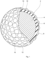
Fig. 1 is a partially cutaway cross-sectional view showing a golf ball according to one embodiment of the present disclosure; -
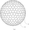
Fig. 2 is a front view of a dimple pattern formed on an outermost cover; -
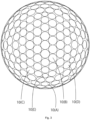
Fig. 3 is a plane view of a dimple pattern formed on an outermost cover; and -
Fig. 4 is an enlarged sectional view of dimples formed on an outermost cover. - The present disclosure provides a golf ball comprising a spherical core, an intermediate layer positioned outside the spherical core, and an outermost cover positioned outside the intermediate layer and having a plurality of dimples formed thereon, wherein
- a center hardness Ho (Shore C hardness) of the spherical core,
- a surface hardness Hs (Shore C hardness) of the spherical core,
- a hardness difference S=Hs-Ho,
- a material hardness Hm (Shore D hardness) of the intermediate layer,
- a material hardness Hc (Shore D hardness) of the outermost cover,
- a thickness Tc (mm) of the outermost cover, and
- a total lower volume Vi (mm3) of the plurality of dimples satisfy Vi>365 and (Hc/Tc)×(S×Hm/Vi)≤130.
- The golf ball according to the present disclosure comprises a spherical core, an intermediate layer positioned outside of the spherical core, and an outermost cover positioned outside of the intermediate layer and having a plurality of dimples formed thereon.
- Examples of the construction of the golf ball include a three-piece golf ball composed of a single-layered spherical core, an intermediate layer covering the spherical core, and an outermost cover covering the intermediate layer; and a multi-piece golf ball (a four-piece golf ball, a five-piece golf ball, or the like) composed of a single-layered spherical core, two or more intermediate layers covering the spherical core, and an outermost cover covering the intermediate layers.
- The construction of the spherical core may be a single-layered construction, or a multi-layered construction, and the single-layered construction is preferable. The construction of the intermediate layer may be a single-layered construction, or a multi-layered construction composed of at least two layers.
- The diameter of the spherical core is preferably 34.8 mm or more, more preferably 36.8 mm or more, and even more preferably 38.8 mm or more, and is preferably 42.2 mm or less, more preferably 41.8 mm or less, even more preferably 41.2 mm or less, and most preferably 40.8 mm or less. If the diameter of the spherical core falls within the above range, the golf ball has better flight distance performance or shot feeling.
- When the spherical core has a diameter in the range from 34.8 mm to 42.2 mm, the compression deformation amount of the spherical core (shrinking amount of the spherical core along the compression direction) when applying a load from an initial load of 98 N to a final load of 1275 N to the spherical core is preferably 2.0 mm or more, more preferably 2.5 mm or more, and even more preferably 3.0 mm or more, and is preferably 5.0 mm or less, more preferably 4.5 mm or less, and even more preferably 4.0 mm or less. If the compression deformation amount falls within the above range, the shot feeling is better.
- The surface hardness (Hs) of the spherical core is not particularly limited, but the surface hardness (Hs) is preferably 60 or more, more preferably 65 or more, and even more preferably 70 or more, and is preferably 95 or less, more preferably 90 or less, and even more preferably 85 or less in Shore C hardness. If the surface hardness (Hs) falls within the above range, better shot feeling is obtained.
- The center hardness (Ho) of the spherical core is not particularly limited, but the center hardness (Ho) is preferably 45 or more, more preferably 47 or more, and even more preferably 49 or more, and is preferably 74 or less, more preferably 72 or less, and even more preferably 70 or less in Shore C hardness. If the center hardness (Ho) falls within the above range, better shot feeling is obtained.
- The hardness difference S (=Hs-Ho) between the surface hardness (Hs) and the center hardness (Ho) of the spherical core is preferably 3 or more, more preferably 5 or more, and even more preferably 7 or more, and is preferably less than 20, more preferably 18 or less, and even more preferably 16 or less in Shore C hardness. If the hardness difference S is less than 20, the spin rate becomes higher and thus the controllability on various iron shots is better. If the hardness difference S is 3 or more, the flight distance on a driver shot is greater.
- The hardness (H10) at 10 mm point from the center of the spherical core in the radius direction is not particularly limited, but the hardness (H10) is preferably 60 or more, more preferably 62 or more, and even more preferably 64 or more, and is preferably 84 or less, more preferably 82 or less, and even more preferably 80 or less in Shore C hardness. If the hardness (H10) falls within the above range, better shot feeling is obtained.
- In the spherical core of the present disclosure, the value (H10-Ho)/S is preferably more than 0.35, more preferably 0.38 or more, and even more preferably 0.40 or more, and is preferably less than 0.6, more preferably 0.58 or less, and even more preferably 0.56 or less. If the value (H10-Ho)/S falls within the above range, it indicates that the hardness of the core changes linearly. When the hardness of the core increases linearly, the core deforms smoothly at shotting, resulting in a better shot feeling on a driver shot.
- The material hardness Hm of the intermediate layer composition constituting the intermediate layer is preferably 50 or more, more preferably 52 or more, and even more preferably 54 or more, and is preferably 73 or less, more preferably 72 or less, and even more preferably 70 or less in Shore D hardness. If the material hardness Hm is 50 or more, the flight distance is better due to the low spin rate on a driver shot, and if the material hardness Hm is 73 or less, better shot feeling is obtained when the golf ball is hit. It is noted that in the case of comprising a plurality of intermediate layers, the material hardness of the intermediate layer composition constituting the outermost intermediate layer is adopted as the material hardness Hm.
- The thickness Tm of the intermediate layer is preferably 0.8 mm or more, more preferably 0.9 mm or more, and even more preferably 1.0 mm or more, and is preferably 3.0 mm or less, more preferably 2.7 mm or less, and even more preferably 2.5 mm or less. If the thickness Tm is 0.8 mm or more, the durability is better, and if the thickness Tm is 3.0 mm or less, better shot feeling is obtained. It is noted that in the case of comprising a plurality of intermediate layers, the total thickness of all the intermediate layers is adopted as the thickness Tm of the intermediate layer.
- The material hardness Hc of the cover composition constituting the outermost cover is preferably 20 or more, more preferably 22 or more, and even more preferably 24 or more, and is preferably 40 or less, more preferably 39 or less, and even more preferably 38 or less in Shore D hardness. If the material hardness Hc is 20 or more, the spin rate on a driver shot is not excessively high and thus the flight distance performance is better, and if the material hardness Hc is 40 or less, the spin performance on an approach shot is better.
- The thickness Tc of the outermost cover is preferably 0.4 mm or more, more preferably 0.5 mm or more, and even more preferably 0.6 mm or more, and is preferably 1.0 mm or less, more preferably 0.9 mm or less, and even more preferably 0.8 mm or less. If the thickness Tc is 0.4 mm or more, the spin performance on an approach shot is better, and if the thickness Tc is 1.0 mm or less, the spin rate on a driver shot is not excessively high and thus the flight distance performance is better.
- The value (Hc/Tc) of the slab hardness Hc (Shore D) to the thickness Tc (mm) of the outermost cover is preferably 30 or more, more preferably 33 or more, and even more preferably 35 or more, and is preferably 75 or less, more preferably 72 or less, and even more preferably 70 or less. If the value (Hc/Tc) is 30 or more, the resilience performance is better, and if the value (Hc/Tc) is 75 or less, better shot feeling is obtained when the golf ball is hit.
- The golf ball according to the present disclosure comprises an outermost cover having a plurality of dimples formed thereon. The dimples are concaves formed on the outermost cover. Next, the dimples formed on the outermost cover of the golf ball according to the present disclosure will be described with reference to the figures.
- A
golf ball 2 shown inFig. 1 comprises aspherical core 4, anintermediate layer 6 covering thecore 4, and anoutermost cover 8 positioned outside theintermediate layer 6. Thegolf ball 2 has a plurality ofdimples 10 on the surface. Other portions than thedimples 10 on the surface of thegolf ball 2 are lands 12. Thegolf ball 2 is provided with a paint layer and a mark layer on an outer side of theoutermost cover 8, but these layers are not depicted. - As shown in
Fig. 2 andFig. 3 , the outermost cover of thegolf ball 2 has a plurality ofdimples 10 formed on the surface. Each of thedimples 10 has a circle contour. -
Fig. 4 shows a cross section of thegolf ball 2 along a plane passing through the central point of thedimple 10 and the central point of thegolf ball 2. The top-to-bottom direction inFig. 4 is the depth direction of thedimple 10. InFig. 4 , a chain double-dashedline 14 indicates a virtual sphere. The surface of thevirtual sphere 14 is the surface of thegolf ball 2 when it is virtualized that nodimple 10 exists. The diameter of thevirtual sphere 14 is equal to the diameter of thegolf ball 2. Thedimple 10 is recessed from the surface of thevirtual sphere 14. Theland 12 coincides with the surface of thevirtual sphere 14. In the present embodiment, the cross-sectional shape of thedimple 10 is substantially a circular arc. The curvature radius of this circular arc is shown by a reference sign CR inFig. 4 . - In
Fig. 4 , an arrow Dm indicates the diameter of thedimple 10. The diameter Dm is a distance between one tangent point Ed and another tangent point Ed when a tangent line Tg traversing two sides of thedimple 10 is drawn. The tangent point Ed is also the edge of thedimple 10. The edge Ed defines the contour of thedimple 10. - In the present disclosure, the "volume of the dimple" means the volume of the portion surrounded by the surface of the
dimple 10 and the surface of the virtual sphere including the contour of thedimple 10. The "volume of the dimple" is divided by a plane connecting intersection points Ed-Ed of the surface of thevirtual sphere 14 with the surface of the dimple. The "upper volume of the dimple" is the volume of the dimple upper part surrounded by the surface of thevirtual sphere 14 and the plane connecting the intersection points Ed-Ed of the surface of the dimple. The "lower volume of the dimple" is the volume of the dimple lower part surrounded by the plane connecting the intersection points Ed-Ed of the surface of the dimple and the surface of thedimple 10. The volume of the dimple is the sum of the upper volume and the lower volume. The "total volume V of the dimples" in the present disclosure is the sum of the volume of all the dimples. The "total upper volume Vo of the dimples" is the sum of the upper volume of all the dimples. The "total lower volume Vi of the dimples" is the sum of the lower volume of all the dimples. When the total upper volume of the dimples is Vo, and the total lower volume of the dimples is Vi, so V=Vo+Vi. - The total lower volume Vi of the plurality of dimples of the golf ball is more than 365 mm3, preferably 380 mm3 or more, more preferably 400 mm3 or more. If the total lower volume Vi is more than 365 mm3, the lift force that acts upon the golf ball is suppressed due to the backspin, and the excess lift on a driver shot is suppressed. The total lower volume Vi is preferably 500 mm3 or less, more preferably 495 mm3 or less, and even more preferably 490 mm3 or less. If the total lower volume Vi is 500 mm3 or less, the lift force that acts upon the golf ball on a driver shot is fully obtained, and the flight distance performance is better.
- The diameter Dm of the
dimple 10 is preferably 2.0 mm or more, more preferably 2.5 mm or more, and even more preferably 2.8 mm or more, and is preferably 6.0 mm or less, more preferably 5.5 mm or less, and even more preferably 5.0 mm or less. If the diameter Dm is 2.0 mm or more, the dimples easily contribute to the turbulent air flow, and if the diameter Dm is 6.0 mm or less, the nature of the golf ball that is substantially a spherical body can be kept. - The plurality of dimples may be a plurality of dimples with a single diameter, or a combination of dimples with various types of diameters. The
golf ball 2 shown inFig. 2 andFig. 3 has five types of dimples, i.e. a dimple A with a diameter of 4.400 mm, a dimple B with a diameter of 4.285 mm, a dimple C with a diameter of 4.150 mm, a dimple D with a diameter of 3.875 mm, and a dimple E with a diameter of 3.000 mm. - In
Fig. 4 , a double ended arrow Dp1 indicates a first depth of thedimple 10. The first depth Dp1 is the distance between the deepest part of thedimple 10 and the surface of thevirtual sphere 14. - The first depth Dp1 is preferably 0.15 mm or more, more preferably 0.17 mm or more, and even more preferably 0.20 mm or more, and is preferably 0.45 mm or less, more preferably 0.43 mm or less, and even more preferably 0.40 mm or less. If the first depth Dp1 is 0.15 mm or more, the lift force obtained by the dimples fully occurs, and if the first depth Dp1 is 0.45 mm or less, the nature of the golf ball that is substantially a spherical body can be kept.
- In
Fig. 4 , a double ended arrow Dp2 indicates a second depth of thedimple 10. The second depth Dp2 is the distance between the deepest part of thedimple 10 and the tangent line Tg. - The second depth Dp2 is preferably 0.08 mm or more, more preferably 0.10 mm or more, and even more preferably 0.12 mm or more, and is preferably 0.30 mm or less, more preferably 0.28 mm or less, and even more preferably 0.26 mm or less. If the second depth Dp2 is 0.08 mm or more, the dimples easily contribute to the turbulent air flow, and if the second depth Dp2 is 0.30 mm or less, the lift force obtained by the dimples is not excessively great, and the flight distance performance on a driver shot is better.
- The area A of the
dimple 10 is the area of a region surrounded by the contour of thedimple 10 when the central point of thegolf ball 2 is viewed at infinity. In the case that thedimple 10 has a circular shape, the area A is calculated by the following mathematical formula.
- In the
golf ball 2 shown inFig. 2 andFig. 3 , the area of the dimple A is 15.21 mm2, the area of the dimple B is 14.42 mm2, the area of the dimple C is 13.53 mm2, the area of the dimple D is 11.79 mm2, and the area of the dimple E is 7.07 mm2. - The ratio (total areas of dimples/surface area of virtual sphere) of the sum of the areas A of all the
dimples 10 to the surface area of thevirtual sphere 14 is referred to as an occupation ratio So. The occupation ratio So is preferably 70% or more, more preferably 75% or more, and even more preferably 80% or more, and is preferably 95% or less, more preferably 92% or less, and even more preferably 90% or less. If the occupation ratio So falls within the above range, the effect of the turbulence by the dimples is greater. - The number of the dimples can be appropriately adjusted depending on the diameter or occupation ratio of the dimples. It is noted that from the viewpoint of the occupation ratio or the function of the respective dimple, the total number of the
dimples 10 is preferably 250 or more, more preferably 280 or more, and even more preferably 300 or more, and is preferably 450 or less, more preferably 410 or less, and even more preferably 390 or less. - The golf ball according to the present disclosure satisfies (Hc/Tc)×(S×Hm/Vi)≤130. Here, S is the hardness difference between the surface hardness Hs and the center hardness Ho of the spherical core, Hm is the material hardness of the intermediate layer, Hc is the material hardness of the outermost cover, Tc is the thickness of the outermost cover, and Vi is the total lower volume of the dimples. The value (Hc/Tc)×(S×Hm/Vi) is preferably 55 or more, more preferably 57 or more, and even more preferably 60 or more, and is preferably 130 or less, more preferably 125 or less, and even more preferably 120 or less. If the value (Hc/Tc)×(S×Hm/Vi) falls within the above range, the difference in the flight distance on a driver shot between hit at a high head speed and hit at a low head speed is small.
- The value (Hm/Vi) is preferably 0.08 or more, more preferably 0.09 or more, and even more preferably 0.10 or more, and is preferably 0.22 or less, more preferably 0.20 or less, and even more preferably 0.18 or less. If the value (Hm/Vi) falls within the above range, lowering in the spin rate on a driver shot and the turbulent air flow by the dimples fully occur, and thus the flight distance performance is better.
- The golf ball according to the present disclosure preferably satisfies the surface hardness Hs (Shore C hardness) of the spherical core < the surface hardness Hms (Shore C hardness) of the intermediate layer > the surface hardness Hcs (Shore C hardness) of the golf ball.
- The difference (Hms-Hcs) between the surface hardness Hms of the intermediate layer and the surface hardness Hcs of the golf ball is preferably more than 0, more preferably 2 or more, and even more preferably 4 or more in Shore C hardness. If the difference (Hms-Hcs) is more than 0, the spin performance on an approach shot is better since the deformation of the cover when the golf ball is hit is greater. It is noted that the upper limit of the difference (Hms-Hcs) is not particularly limited, but it is about 20 in Shore C hardness.
- The difference (Hms-Hs) between the surface hardness Hms of the intermediate layer and the surface hardness Hs of the spherical core is preferably more than 0, more preferably 2 or more, and even more preferably 4 or more in Shore C hardness. If the difference (Hms-Hs) is more than 0, the whole intermediate layer-covering spherical body having the intermediate layer formed on the surface of the spherical core has a greater degree of an outer-hard and inner-soft structure, and the spin rate on a driver shot can be suppressed.
- The golf ball according to the present disclosure preferably has a diameter ranging from 40 mm to 45 mm. In light of satisfying the regulation of US Golf Association (USGA), the diameter is particularly preferably 42.67 mm or more. In light of prevention of air resistance, the diameter is more preferably 44 mm or less, and particularly preferably 42.80 mm or less. In addition, the golf ball according to the present disclosure preferably has a mass of 40 g or more and 50 g or less. In light of obtaining greater inertia, the mass is more preferably 44 g or more, and particularly preferably 45.00 g or more. In light of satisfying the regulation of USGA, the mass is particularly preferably 45.93 g or less.
- When the golf ball has a diameter in the range of from 40 mm to 45 mm, the compression deformation amount (shrinking amount along the compression direction) of the golf ball when applying a load from an initial load of 98 N to a final load of 1275 N to the golf ball is preferably 2.0 mm or more, more preferably 2.1 mm or more, and even more preferably 2.2 mm or more, and is preferably 3.0 mm or less, more preferably 2.9 mm or less, and even more preferably 2.8 mm or less. If the compression deformation amount falls within the above range, the golf ball has better shot feeling.
- Next, the materials for forming the constituent members of the golf ball according to the present disclosure will be explained.
- The spherical core of the golf ball according to the present disclosure is preferably formed from a rubber composition (hereinafter sometimes referred to as "core rubber composition") containing (a) a base rubber, (b) an α,β-unsaturated carboxylic acid having 3 to 8 carbon atoms and/or a metal salt thereof as a co-crosslinking agent, and (c) a crosslinking initiator.
- As (a) the base rubber, a natural rubber and/or a synthetic rubber can be used. For example, a polybutadiene rubber, a natural rubber, a polyisoprene rubber, a styrene polybutadiene rubber, or an ethylene-propylene-diene rubber (EPDM) can be used. These rubbers may be used solely, or at least two of these rubbers may be used in combination.
- (b) The α,β-unsaturated carboxylic acid having 3 to 8 carbon atoms and/or the metal salt thereof is blended as a co-crosslinking agent in the rubber composition, and has an action of crosslinking a rubber molecule by graft polymerization to a base rubber molecular chain.
- Examples of the α,β-unsaturated carboxylic acid having 3 to 8 carbon atoms include acrylic acid, methacrylic acid, fumaric acid, maleic acid and crotonic acid.
- Examples of the metal ion constituting the metal salt of the α,β-unsaturated carboxylic acid having 3 to 8 carbon atoms include a monovalent metal ion such as sodium, potassium and lithium; a divalent metal ion such as magnesium, calcium, zinc, barium and cadmium; a trivalent metal ion such as aluminum; and other metal ions such as tin and zirconium. The above metal component may be used solely or as a mixture of at least two of them. Among them, the divalent metal ion such as magnesium, calcium, zinc, barium and cadmium is preferably used as the metal component. This is because if the divalent metal salt of the α,β-unsaturated carboxylic acid having 3 to 8 carbon atoms is used, a metal crosslinking easily generates between the rubber molecules. Especially, as the divalent metal salt, zinc acrylate is preferable, because zinc acrylate enhances the resilience of the obtained golf ball. It is noted that the α,β-unsaturated carboxylic acid having 3 to 8 carbon atoms and/or the metal salt thereof may be used solely or as a mixture of at least two of them.
- The amount of (b) the α,β-unsaturated carboxylic acid having 3 to 8 carbon atoms and/or the metal salt thereof may be appropriately adjusted depending on the desired hardness of the spherical core. For example, the amount of the component (b) is preferably 15 parts by mass or more, more preferably 20 parts by mass or more, and is preferably 50 parts by mass or less, more preferably 40 parts by mass or less, with respect to 100 parts by mass of (a) the base rubber.
- (c) The crosslinking initiator is blended to crosslink (a) the base rubber component. As (c) the crosslinking initiator, an organic peroxide is suitable. Specific examples of the organic peroxide include dicumyl peroxide, 1,1-bis(t-butylperoxy)-3,3,5-trimethylcyclohexane, 2,5-dimethyl-2,5-di(t-butylperoxy) hexane and di-t-butyl peroxide. These organic peroxides may be used solely or as a mixture of at least two of them. Among them, dicumyl peroxide is preferably used.
- The amount of (c) the crosslinking initiator may be appropriately adjusted depending on the desired hardness of the spherical core. For example, the amount of (c) the crosslinking initiator is preferably 0.2 part by mass or more, more preferably 0.4 part by mass or more, and is preferably 5.0 parts by mass or less, more preferably 2.5 parts by mass or less, and even more preferably 1.0 part by mass or less, with respect to 100 parts by mass of (a) the base rubber.
- In the case that the co-crosslinking agent of the rubber composition consists of the α,β-unsaturated carboxylic acid having 3 to 8 carbon atoms, the rubber composition preferably further contains (d) a metal compound. This is because if the α,β-unsaturated carboxylic acid having 3 to 8 carbon atoms is neutralized with the metal compound in the rubber composition, substantially the same effect as using the metal salt of the α,β-unsaturated carboxylic acid having 3 to 8 carbon atoms as the co-crosslinking agent is provided. In addition, in the case that the α,β-unsaturated carboxylic acid having 3 to 8 carbon atoms and the metal salt thereof are used in combination as the co-crosslinking agent, (d) the metal compound may be used.
- (d) The metal compound is not particularly limited, as long as it can neutralize (b) the α,β-unsaturated carboxylic acid having 3 to 8 carbon atoms in the rubber composition. Examples of (d) the metal compound include a metal hydroxide such as magnesium hydroxide, zinc hydroxide, calcium hydroxide, sodium hydroxide, lithium hydroxide, potassium hydroxide, and copper hydroxide; a metal oxide such as magnesium oxide, calcium oxide, zinc oxide, and copper oxide; and a metal carbonate such as magnesium carbonate, zinc carbonate, calcium carbonate, sodium carbonate, lithium carbonate, and potassium carbonate. As (d) the metal compound, the divalent metal compound is preferable, the zinc compound is more preferable. This is because the divalent metal compound reacts with the α,β-unsaturated carboxylic acid having 3 to 8 carbon atoms to form a metal crosslinking. (d) The metal compound may be used solely, or at least two of them may be used in combination.
- The rubber composition may further contain (e) an organic sulfur compound. (e) The organic sulfur compound enhances the resilience of the spherical core. (e) The organic sulfur compound is not particularly limited, as long as it is an organic compound having a sulfur atom in the molecule thereof. Examples of (e) the organic sulfur compound include an organic compound having a thiol group (-SH) or a polysulfide bond having 2 to 4 sulfur atoms (-S-S-, -S-S-S-, or -S-S-S-S-), and a metal salt thereof (-SM, -S-M-S- or the like; M is a metal atom). (e) The organic sulfur compound may be used solely or as a mixture of at least two of them.
- Examples of (e) the organic sulfur compound include thiophenols, thionaphthols, polysulfides, thiurams, thiocarboxylic acids, dithiocarboxylic acids, sulfenamides, dithiocarbamates, and thiazoles. As the organic sulfur compound, diphenyl disulfides (e.g. diphenyl disulfide, bis(pentabromophenyl) disulfide), thiophenols, and thionaphthols (e.g. 2-thionaphthol) can be suitably used.
- The amount of (e) the organic sulfur compound may be appropriately adjusted depending on the desired resilience performance of the spherical core. For example, the amount of (e) the organic sulfur compound is preferably 0.05 part by mass or more, more preferably 0.1 part by mass or more, and is preferably 5.0 parts by mass or less, more preferably 3.0 parts by mass or less, with respect to 100 parts by mass of (a) the base rubber.
- The rubber composition may further contain (f) a carboxylic acid and/or a metal salt thereof. As (f) the carboxylic acid and/or the metal salt thereof, a carboxylic acid having 1 to 30 carbon atoms and/or a metal salt thereof is preferable. As the carboxylic acid, an aliphatic carboxylic acid (a saturated fatty acid or an unsaturated fatty acid), or an aromatic carboxylic acid (e.g. benzoic acid) can be used. The amount of (f) the carboxylic acid and/or the metal salt thereof is preferably 1 part by mass or more and 40 parts by mass or less with respect to 100 parts by mass of the base rubber.
- The rubber composition may further contain an additive such as a filler for adjusting weight or the like, an antioxidant, a peptizing agent, and a softener, where necessary.
- The filler blended in the rubber composition is mainly used as a weight adjusting agent for adjusting the weight of the golf ball obtained as a final product, and may be blended where necessary. Examples of the filler include an inorganic filler such as barium sulfate, calcium carbonate, magnesium oxide, tungsten powder, and molybdenum powder.
- The rubber composition can be obtained by kneading (a) the base rubber, (b) the α,β-unsaturated carboxylic acid having 3 to 8 carbon atoms and/or the metal salt thereof, (c) the crosslinking initiator, and the other optional components. The kneading method is not particularly limited. For example, the kneading can be conducted with a conventional kneading machine such as a kneading roll, a banbury mixer and a kneader.
- The spherical core can be molded, for example, by heat pressing the core rubber composition. The molding conditions for heat pressing the core rubber composition may be determined appropriately depending on the rubber composition. Generally, the heat pressing is preferably carried out at a temperature of 130 °C to 200 °C for 10 to 60 minutes, or carried out in a two-step heating of heating at a temperature of 130 °C to 150 °C for 20 to 40 minutes followed by heating at a temperature of 160 °C to 180 °C for 5 to 15 minutes.
- The golf ball according to the present disclosure has an intermediate layer covering the spherical core. The intermediate layer is preferably formed from an intermediate layer composition containing a resin component.
- The golf ball according to the present disclosure has an outermost cover positioned outside of the intermediate layer. The outermost cover is preferably formed from a cover composition containing a resin component.
- Examples of the resin component used in the resin composition forming the outermost cover and the intermediate layer include an ionomer resin, a urethane resin (a thermoplastic polyurethane elastomer or a thermosetting polyurethane elastomer), a thermoplastic styrene elastomer, a thermoplastic polyamide elastomer, and a thermoplastic polyester elastomer.
- Examples of the ionomer resin include a binary ionomer resin prepared by neutralizing at least a part of carboxyl groups in a binary copolymer composed of an olefin and an α, β-unsaturated carboxylic acid having 3 to 8 carbon atoms with a metal ion, a ternary ionomer resin prepared by neutralizing at least a part of carboxyl groups in a ternary copolymer composed of an olefin, an α, β-unsaturated carboxylic acid having 3 to 8 carbon atoms and an α, β-unsaturated carboxylic acid ester with a metal ion, and a mixture of those.
- Examples of the binary ionomer resin include Himilan (registered trademark) 1555 (Na), 1557 (Zn), 1605 (Na), 1706 (Zn), 1707 (Na), AM7311 (Mg), AM7329 (Zn), AM7337 (available from Dow-Mitsui Polychemicals Co., Ltd.); Surlyn (registered trademark) 8945 (Na), 9945 (Zn), 8140 (Na), 8150 (Na), 9120 (Zn), 9150 (Zn), 6910 (Mg), 6120 (Mg), 7930 (Li), 7940 (Li), AD8546 (Li) (available from E.I. du Pont de Nemours and Company); and lotek (registered trademark) 8000 (Na), 8030 (Na), 7010 (Zn), 7030 (Zn) (available from ExxonMobil Chemical Corporation).
- Examples of the ternary ionomer resin include Himilan AM7327 (Zn), 1855 (Zn), 1856 (Na), AM7331 (Na) (available from Dow-Mitsui Polychemicals Co., Ltd.); Surlyn 6320 (Mg), 8120 (Na), 8320 (Na), 9320 (Zn), 9320W (Zn), HPF1000 (Mg), HPF2000 (Mg) (available from E.I. du Pont de Nemours and Company); and Iotek7510 (Zn), 7520 (Zn) (available from ExxonMobil Chemical Corporation). It is noted that Na, Zn, Li, Mg or the like described in the parentheses after the trade names of the ionomer resin indicate metal ion type for neutralizing the ionomer resin.
- The thermoplastic polyurethane elastomer has a urethane bond in the molecule. The urethane bond may be formed by a reaction between a polyol and a polyisocyanate. The polyol which is the raw material for the urethane bond has a plurality of hydroxy groups, and a low molecular weight polyol or a high molecular weight polyol may be used.
- Specific examples of the thermoplastic polyurethane elastomer include Elastollan (registered trademark) NY80A, NY84A, NY88A, NY95A, ET885, ET890 (available from BASF Japan Ltd.).
- As the thermoplastic styrene based elastomer, a styrene block-containing thermoplastic elastomer can be suitably used. The styrene block-containing thermoplastic elastomer has a polystyrene block as a hard segment, and a soft segment.
- The styrene block-containing thermoplastic elastomer includes a styrenebutadiene-styrene block copolymer (SBS), a styrene-isoprene-styrene block copolymer (SIS), a styrene-isoprene-butadiene-styrene block copolymer (SIBS), a hydrogenated product of SBS, a hydrogenated product of SIS, and a hydrogenated product of SIBS. Examples of the hydrogenated product of SBS include a styrene-ethylene-butylene-styrene block copolymer (SEBS). Examples of the hydrogenated product of SIS include a styrene-ethylene-propylene-styrene block copolymer (SEPS). Examples of the hydrogenated product of SIBS include a styrene-ethylene-ethylene-propylene-styrene block copolymer (SEEPS).
- Examples of the thermoplastic styrene based elastomer include TEFABLOC T3221C, T3339C, SJ4400N, SJ5400N, SJ6400N, SJ7400N, SJ8400N, SJ9400N, SR04 (available from Mitsubishi Chemical Corporation).
- The cover composition constituting the outermost cover preferably contains the polyurethane and/or the ionomer resin as the resin component, and particularly preferably contains the polyurethane as the resin component. If the outermost cover contains the polyurethane as the resin component, the bite of the outermost cover into the club face on a driver shot is greater, and thus the spin rate is easily increased.
- In the case that the cover composition contains the polyurethane as the resin component, the amount of the polyurethane in the resin component is preferably 50 mass % or more, more preferably 60 mass % or more, and even more preferably 70 mass % or more. The resin component of the cover composition may consist of the polyurethane (preferably the thermoplastic polyurethane elastomer).
- In the case that the cover composition contains the ionomer resin as the resin component, the amount of the ionomer resin in the resin component is preferably 50 mass % or more, more preferably 60 mass % or more, and even more preferably 70 mass % or more. When the ionomer resin is contained, it is also preferable that the thermoplastic styrene elastomer is used in combination.
- The intermediate layer composition preferably contains the ionomer resin as the resin component. When the ionomer resin is contained, it is also preferable that the thermoplastic styrene elastomer is used in combination. The amount of the ionomer resin in the resin component of the intermediate layer composition is preferably 50 mass % or more, more preferably 60 mass % or more, and even more preferably 70 mass % or more.
- The outermost cover composition and the intermediate layer composition may contain a pigment component such as a white pigment (e.g. titanium oxide), a blue pigment and a red pigment, a weight adjusting agent such as zinc oxide, calcium carbonate and barium sulfate, a dispersant, an antioxidant, an ultraviolet absorber, a light stabilizer, a fluorescent material or fluorescent brightener, or the like, in addition to the above resin component.
- The amount of the white pigment (e.g. titanium oxide) is preferably 0.5 part by mass or more, more preferably 1 part by mass or more, and is preferably 10 parts by mass or less, more preferably 8 parts by mass or less, with respect to 100 parts by mass of the base resin constituting the outermost cover. If the amount of the white pigment is 0.5 part by mass or more, it is possible to impart the opacity to the cover. In addition, if the amount of the white pigment is 10 parts by mass or less, the obtained cover has better durability.
- The method for forming the intermediate layer is not particularly limited, and examples thereof include a method which comprises molding the intermediate layer composition into a hemispherical half-shell in advance, covering the spherical core with two of the half-shells, and performing compression molding; and a method which comprises injection molding the intermediate layer composition directly onto the spherical core to cover the spherical core.
- Examples of the method for molding the cover include a method which comprises molding the cover composition into a hollow shell, covering the spherical body (the spherical body having the spherical core and the intermediate layer) with a plurality of the hollow shells, and performing compression molding (preferably a method which comprises molding the cover composition into a hollow half-shell, covering the spherical body with two of the half-shells, and performing compression molding); and a method which comprises injection molding the cover composition directly onto the spherical body.
- The golf ball body having the cover formed thereon is ejected from the mold, and is preferably subjected to surface treatments such as deburring, cleaning and sandblast where necessary.
- In addition, if desired, a paint film or a mark may be formed. The thickness of the paint film is not particularly limited, and is preferably 5 µm or more, more preferably 6 µm or more, and even more preferably 7 µm or more, and is preferably 50 µm or less, more preferably 40 µm or less, and even more preferably 30 µm or less. If the thickness of the paint film is 5 µm or more, the paint film is hard to wear off even if the golf ball is used continuously, and if the thickness of the paint film is 50 µm or less, the dimple effect is fully obtained. It is noted that the effect of the present disclosure is not impaired since the paint film is very thin.
- Next, the present disclosure will be described in detail by way of examples. However, the present disclosure is not limited to the examples described below. Various changes and modifications without departing from the spirit of the present disclosure are included in the scope of the present disclosure.
- Sheets with a thickness of about 2 mm were produced by injection molding the intermediate layer composition or the cover composition. The sheets were stored at a temperature of 23 °C for two weeks. At least three of these sheets were stacked on one another so as not to be affected by the measuring substrate on which the sheets were placed, and the hardness of the stack was measured with an automatic hardness tester (Digitest II, available from Bareiss company) using a testing device of "Shore D".
- The compression deformation amount was measured with a YAMADA type compression tester "SCH". The golf ball or spherical core was placed on a metal rigid plate of the tester. A metal cylinder slowly fell toward the golf ball or spherical core. The golf ball or spherical core sandwiched between the bottom of the cylinder and the rigid plate deformed. The travelling distance of the cylinder when applying a load from an initial load of 98 N to a final load of 1275 N to the golf ball or spherical core was measured. The compression deformation amount (mm) is the travelling distance. The travelling speed of the cylinder before applying the initial load was 0.83 mm/s. The travelling speed of the cylinder when applying the load from the initial load to the final load was 1.67 mm/s.
- The hardness measured at the surface portion of the core was adopted as the surface hardness of the core. In addition, the core was cut into two hemispheres to obtain a cut plane, and the hardness at the central point of the cut plane and the hardness at the predetermined distance from the central point in the radius direction were measured. It is noted that the core hardness was measured at four points at the predetermined distance from the central point of the core cut plane, and the average value thereof was calculated. The hardness was measured with an automatic hardness tester (Digitest II, available from Bareiss company) using a testing device of "Shore C".
- The hardness measured at the land on the surface portion of the golf ball was adopted as the surface hardness of the golf ball. In addition, the hardness measured at the surface portion of the intermediate layer-covering spherical body having the intermediate layer formed on the surface of the spherical core was adopted as the surface hardness of the intermediate layer. Each hardness was measured at four points and the average value thereof was calculated. The hardness was measured with an automatic hardness tester (Digitest II, available from Bareiss company) using a testing device of "Shore C".
- A driver (trade name "SRIXON ZX7", Shaft hardness: S, Loft angle: 10.5°, available from Sumitomo Rubber Industries, Ltd.) was installed on a swing machine available from Golf Laboratories, Inc. The hitting point was set at the face center. The golf ball was hit at a head speed of 45 m/sec, and the ball speed (m/s) and spin rate (rpm) right after hitting the golf ball and the flight distance (the distance from the launch point to the stop point) were measured. The measurement was conducted twelve times for each golf ball, and the average value of the obtained data was adopted as the measurement value for that golf ball.
- A driver (trade name "XXIO12", Shaft hardness: R, Loft angle: 10.5°, available from Sumitomo Rubber Industries, Ltd.) was installed on a swing machine available from Golf Laboratories, Inc. The hitting point was set at the face center. The golf ball was hit at a head speed of 35 m/sec, and the ball speed (m/s) and spin rate (rpm) right after hitting the golf ball and the flight distance (the distance from the launch point to the stop point) were measured. The measurement was conducted twelve times for each golf ball, and the average value of the obtained data was adopted as the measurement value for that golf ball.
- According to the formulations shown in Table 1, the materials were kneaded with a kneading roll to obtain the core compositions.


- The materials used in Table 1 are shown as follows.
- Polybutadiene: "BR-730" available from JSR Corporation
- Zinc acrylate: "ZN-DA90S" available from Nisshoku Techno Fine Chemical Co., Ltd.
- Zinc oxide: "Ginrei R" available from Toho Zinc Co., Ltd.
- Barium sulfate: "Barium sulfate BD" available from Sakai Chemical Industry Co., Ltd.
- Benzoic acid: (purity: at least 98%) available from Tokyo Chemical Industry Co. Ltd.
- Bis(pentabromophenyl) disulfide: available from Kawaguchi Chemical Industry Co., Ltd.
- Diphenyl disulfide: available from Sumitomo Seika Chemicals Co., Ltd.
- Dicumyl peroxide: "Percumyl (registered trademark) D" available from NOF Corporation
- According to the formulations shown in Tables 2 and 3, the materials were extruded with a twin-screw kneading type extruder to prepare the intermediate layer compositions/cover compositions in a pellet form.
Table 2 Intermediate layer composition/cover composition No. a b c d e Formulation (parts by mass) Surlyn 8150 - 50 - - - Himilan 1605 50 - 47 - - Himilan AM7329 50 50 50 - - Himilan 1555 - - - 45 41 Himilan 1557 - - - 45 41 TEFABLOC T3221C - - 3 10 18 Titanium dioxide 4 4 4 4 4 Hardness (Shore D) 66 68 63 55 50 - Surlyn (registered trademark) 8150: sodium ion neutralized ethylene-methacrylic acid copolymer ionomer resin available from E.I. du Pont de Nemours and Company
- Himilan (registered trademark) 1605: sodium ion neutralized ethylene-methacrylic acid copolymer ionomer resin available from Dow-Mitsui Polychemicals Co., Ltd.
- Himilan (registered trademark) AM7329: sodium ion neutralized ethylene-methacrylic acid copolymer ionomer resin available from Dow-Mitsui Polychemicals Co., Ltd.
- Himilan (registered trademark) 1555: sodium ion neutralized ethylene-methacrylic acid copolymer ionomer resin available from Dow-Mitsui Polychemicals Co., Ltd.
- Himilan (registered trademark) 1557: zinc ion neutralized ethylene-methacrylic acid copolymer ionomer resin available from Dow-Mitsui Polychemicals Co., Ltd.
- TEFABLOC T3221C: thermoplastic styrene based elastomer available from Mitsubishi Chemical Corporation
- Titanium dioxide: A-220 available from Ishihara Sangyou Kaisha, Ltd.

- Elastollan (registered trademark) NY80A: thermoplastic polyurethane elastomer available from BASF Japan Ltd.
- Elastollan (registered trademark) NY84A: thermoplastic polyurethane elastomer available from BASF Japan Ltd.
- Elastollan (registered trademark) NY88A: thermoplastic polyurethane elastomer available from BASF Japan Ltd.
- Elastollan (registered trademark) NY95A: thermoplastic polyurethane elastomer available from BASF Japan Ltd.
- TINUVIN (registered trademark) 770: hindered amine based light stabilizer available from BASF Japan Ltd.
- Titanium dioxide: A-220 available from Ishihara Sangyo Kaisha, Ltd.
- The core compositions shown in Table 1 were heat-pressed in upper and lower molds, each having a hemispherical cavity, to produce the spherical cores. It is noted that barium sulfate was added in an appropriate amount such that the obtained golf balls had a mass of 45.3 g.
- The intermediate layer composition was injection molded on the spherical core to obtain the intermediate layer-covering spherical body. The obtained intermediate layer-covering spherical body was charged into a final mold provided with a plurality of pimples on the cavity surface. Half shells were obtained from the cover composition by a compression molding method. The intermediate layer-covering spherical body charged into the final mold was covered with two of the half shells to obtain the golf balls having an outermost cover on which a plurality of dimples with an reversed shape of the pimple shape on the cavity surface were formed. The specifications of the dimples formed on the outermost cover are shown in Tables 4 to 5. The evaluation results regarding the obtained golf balls are shown in Tables 6 to 7.
Table 4 Dimple pattern Type Number Diameter Depth Dp1 Depth Dp2 Curvature CR Lower volume Total lower volume (mm) (mm) (mm) (mm) (mm3) Vi (mm3) I A 60 4.400 0.2356 0.1219 19.9 0.93 56 B 158 4.285 0.2297 0.1219 18.9 0.88 139 C 72 4.150 0.2230 0.1219 17.7 0.83 59 D 36 3.875 0.2100 0.1219 15.5 0.72 26 E 12 3.000 0.1747 0.1219 9.3 0.43 5 II A 60 4.400 0.2526 0.1389 17.5 1.06 63 B 158 4.285 0.2467 0.1389 16.6 1.00 158 C 72 4.150 0.2400 0.1389 15.6 0.94 68 D 36 3.875 0.2270 0.1389 13.6 0.82 30 E 12 3.000 0.1917 0.1389 8.2 0.49 6 III A 60 4.400 0.2866 0.1729 14.1 1.32 79 B 158 4.285 0.2807 0.1729 13.4 1.25 197 C 72 4.150 0.2740 0.1729 12.5 1.17 84 D 36 3.875 0.2610 0.1729 10.9 1.02 37 E 12 3.000 0.2257 0.1729 6.6 0.61 7 IV A 60 4.400 0.3036 0.1899 12.8 1.45 87 B 158 4.285 0.2977 0.1899 12.2 1.37 217 C 72 4.150 0.2910 0.1899 11.4 1.29 93 D 36 3.875 0.2780 0.1899 10.0 1.12 40 E 12 3.000 0.2427 0.1899 6.0 0.67 8 V A 60 4.400 0.3206 0.2069 11.8 1.58 95 B 158 4.285 0.3147 0.2069 11.2 1.50 236 C 72 4.150 0.3080 0.2069 10.5 1.40 101 D 36 3.875 0.2950 0.2069 9.2 1.22 44 E 12 3.000 0.2597 0.2069 5.5 0.74 9 Table 5 Dimple pattern No. I II III IV V Front view Fig. 2 Fig. 2 Fig. 2 Fig. 2 Fig. 2 Plane view Fig. 3 Fig. 3 Fig. 3 Fig. 3 Fig. 3 Total number 338 338 338 338 338 Total lower volume Vi (mm3) 285 325 405 445 485 Occupation ratio (%) 81.6 81.6 81.6 81.6 81.6 Table 6 Golf ball No. 1 2 3 4 5 Core Formulation No. B C D B B Diameter (mm) 39.5 39.1 39.5 39.5 39.5 Compression deformation amount (mm) 3.2 3.24 3.18 3.2 3.2 Core center hardness Ho 68.3 67.9 70.7 68.3 68.3 Hardness H10 at 10 mm point 74.8 74.6 75.5 74.8 74.8 Surface hardness Hs 82.3 81.9 79.3 82.3 82.3 (H10-Ho)/S 0.46 0.48 0.56 0.46 0.46 Hardness difference S (=Hs-Ho) 14.0 14.0 8.6 14.0 14.0 Intermediate layer Formulation No. c c c e c Thickness (mm) 1 1 1 1 1 Surface hardness Hms (Shore C) 92 92 92 76 92 Material hardness Hm (Shore D) 63 63 63 50 63 Cover Formulation No. 9 9 9 9 f Thickness Tc (mm) 0.6 0.8 0.6 0.6 0.6 Material hardness Hc (Shore D) 31 31 31 31 27 Dimple Type (pattern) IV IV IV IV IV Lower volume Vi (mm3) 445 445 445 445 445 Golf ball Surface hardness Hcs (Shore C) 84 79 84 71 82 Compression deformation amount (mm) 2.79 2.82 2.77 2.89 2.79 (Hc/Tc)×(S×Hm/Vi) 102.4 76.8 62.9 81.3 89.2 Driver shot (head speed = 45m/s) Spin rate (rpm) 2750 2940 2840 2900 2930 Ball speed (m/s) 65.6 65.4 65.7 65.2 65.6 Flight distance (m) 226.2 224.3 225.4 223.9 224.9 Driver shot (head speed = 35m/s) Spin rate (rpm) 2830 3020 2900 2980 3000 Ball speed (m/s) 50.8 50.7 50.9 50.5 50.8 Flight distance (m) 168.4 167.2 168.1 166.4 167.8 Flight distance difference between H/S45-H/S35 shots 57.8 57.1 57.3 57.5 57.1 Table 6-Continued Golf ball No. 6 7 8 9 10 Core Formulation No. B E B E A Diameter (mm) 39.5 39.5 39.5 39.5 39.5 Compression deformation amount (mm) 3.2 3.16 3.2 3.16 3.21 Core center hardness Ho 68.3 64.8 68.3 64.8 56.1 Hardness H10 at 10 mm point 74.8 72.6 74.8 72.6 67.3 Surface hardness Hs 82.3 82.2 82.3 82.2 81.8 (H10-Ho)/S 0.46 0.45 0.46 0.45 0.44 Hardness difference S (=Hs-Ho) 14.0 17.4 14.0 17.4 25.7 Intermediate layer Formulation No. c c d c e Thickness (mm) 1 1 1 1 1 Surface hardness Hms (Shore C) 92 92 83 92 76 Material hardness Hm (Shore D) 63 63 55 63 50 Cover Formulation No. 9 9 9 f f Thickness Tc (mm) 0.6 0.6 0.6 0.6 0.6 Material hardness Hc (Shore D) 31 31 31 27 27 Dimple Type (pattern) V IV III IV V Lower volume Vi (mm3) 485 445 405 445 485 Golf ball Surface hardness Hcs (Shore C) 84 84 78 82 68 Compression deformation amount (mm) 2.79 2.75 2.87 2.79 2.91 (Hc/Tc)×(S×Hm/Vi) 94.0 127.3 98.2 110.9 119.2 Driver shot (head speed = 45m/s) Spin rate (rpm) 2750 2700 2820 2900 2850 Ball speed (m/s) 65.6 65.7 65.3 65.6 65.1 Flight distance (m) 225.6 227 225.1 225.1 224.8 Driver shot (head speed = 35m/s) Spin rate (rpm) 2830 2790 2890 2970 2920 Ball speed (m/s) 50.8 50.9 50.6 50.8 50.4 Flight distance (m) 168.7 169.1 166.7 168 167.9 Flight distance difference between H/S45-H/S35 shots 56.9 57.9 58.4 57.1 56.9 Table 7 Golf ball No. 11 12 13 14 15 Core Formulation No. E A E B F Diameter (mm) 39.5 39.5 39.5 39.5 39.5 Compression deformation amount (mm) 3.16 3.21 3.16 3.20 3.20 Core center hardness Ho 64.8 56.1 64.8 68.3 55.4 Hardness H10 at 10 mm point 72.6 67.3 72.6 74.8 70.6 Surface hardness Hs 82.2 81.8 82.2 82.3 86.2 (H10-Ho)/S 0.45 0.44 0.45 0.46 0.49 Hardness difference S (=Hs-Ho) 17.4 25.7 17.4 14.0 30.8 Intermediate layer Formulation No. c c b c d Thickness (mm) 1 1 1 1 1 Surface hardness Hms (Shore C) 92 92 97 92 83 Material hardness Hm (Shore D) 63 63 68 63 55 Cover Formulation No. 9 9 h 9 f Thickness Tc (mm) 0.6 0.6 0.6 0.6 0.6 Material hardness Hc (Shore D) 31 31 36 31 27 Dimple Type (pattern) III III IV I IV Lower volume Vi (mm3) 405 405 445 285 445 Golf ball Surface hardness Hcs (Shore C) 84 84 92 84 75 Compression deformation amount (mm) 2.75 2.8 2.66 2.79 2.89 (Hc/Tc)×(S×Hm/Vi) 139.8 206.6 159.5 159.9 171.3 Driver shot (Head speed = 45m/s) Spin rate (rpm) 2700 2630 2560 2750 2650 Ball speed (m/s) 65.7 65.6 65.9 65.6 65.2 Flight distance (m) 227.7 228.4 229.1 227.6 226.9 Driver shot (Head speed = 35m/s) Spin rate (rpm) 2790 2730 2690 2830 2760 Ball speed (m/s) 50.9 50.8 51 50.8 50.5 Flight distance (m) 167.9 168.2 169.2 166.8 167.9 Flight distance difference between H/S45-H/S35 shots 59.8 60.2 59.9 60.8 59 Table 7-Continued Golf ball No. 16 17 18 19 Core Formulation No. B E B E Diameter (mm) 39.5 39.5 39.5 39.5 Compression deformation amount (mm) 3.20 3.16 3.20 3.16 Core center hardness Ho 68.3 64.8 68.3 64.8 Hardness H10 at 10 mm point 74.8 72.6 74.8 72.6 Surface hardness Hs 82.3 82.2 82.3 82.2 (H10-Ho)/S 0.46 0.45 0.46 0.45 Hardness difference S (=Hs-Ho) 14.0 17.4 14.0 17.4 Intermediate layer Formulation No. c a c b Thickness (mm) 1 1 1 1 Surface hardness Hms (Shore C) 92 95 92 97 Material hardness Hm (Shore D) 63 66 63 68 Cover Formulation No. 9 9 e f Thickness Tc (mm) 0.6 0.6 0.6 0.6 Material hardness Hc (Shore D) 31 31 50 27 Dimple Type (pattern) II III IV III Lower volume Vi (mm3) 325 405 445 405 Golf ball Surface hardness Hcs (Shore C) 84 88 87 87 Compression deformation amount (mm) 2.79 2.74 2.65 2.73 (Hc/Tc)×(S×Hm/Vi) 140.2 146.5 165.2 131.5 Driver shot (Head speed = 45m/s) Spin rate (rpm) 2760 2740 2480 2800 Ball speed (m/s) 65.6 65.7 65.9 65.7 Flight distance (m) 227.8 227.4 229.7 226.9 Driver shot (Head speed = 35m/s) Spin rate (rpm) 2830 2830 2600 2880 Ball speed (m/s) 50.8 50.9 51 50.9 Flight distance (m) 167.3 167.5 169.8 167.1 Flight distance difference between H/S45-H/S35 shots 60.5 59.9 59.9 59.8 - It is apparent that the golf ball according to the present disclosure that comprises a spherical core, an intermediate layer positioned outside the spherical core, and an outermost cover positioned outside the intermediate layer and having a plurality of dimples formed thereon, wherein when a center hardness Ho (Shore C hardness) of the spherical core, a surface hardness Hs (Shore C hardness) of the spherical core, a hardness difference S=Hs-Ho, a material hardness Hm (Shore D hardness) of the intermediate layer, a material hardness Hc (Shore D hardness) of the outermost cover, a thickness Tc (mm) of the outermost cover, and a total lower volume Vi (mm3) of the plurality of dimples satisfy Vi>365 and (Hc/Tc)×(S×Hm/Vi)≤130, has a small difference in the flight distance on a driver shot between hit at a high head speed and hit at a low head speed.
- The present disclosure (1) is a golf ball comprising a spherical core, an intermediate layer positioned outside the spherical core, and an outermost cover positioned outside the intermediate layer and having a plurality of dimples formed thereon, wherein when a center hardness Ho (Shore C hardness) of the spherical core, a surface hardness Hs (Shore C hardness) of the spherical core, a hardness difference S=Hs-Ho, a material hardness Hm (Shore D hardness) of the intermediate layer, a material hardness Hc (Shore D hardness) of the outermost cover, a thickness Tc (mm) of the outermost cover, and a total lower volume Vi (mm3) of the plurality of dimples satisfy Vi>365 and (Hc/Tc)×(S×Hm/Vi)≤130.
- The present disclosure (2) is the golf ball according to the present disclosure (1), wherein 0.35<(H10-Ho)/S<0.6 is satisfied where H10 is a hardness at 10 mm point from a center of the spherical core.
- The present disclosure (3) is the golf ball according to the present disclosure (1) or (2), wherein the hardness difference S<20.
- The present disclosure (4) is the golf ball according to any one of the present disclosures (1) to (3), wherein Vi≥380.
- The present disclosure (5) is the golf ball according to any one of the present disclosures (1) to (4), wherein Vi≥400.
- The present disclosure (6) is the golf ball according to any one of the present disclosures (1) to (5), wherein the surface hardness (Shore C hardness) of the spherical core < a surface hardness (Shore C hardness) of the intermediate layer > a surface hardness (Shore C hardness) of the golf ball is satisfied.
- The present disclosure (7) is the golf ball according to any one of the present disclosures (1) to (6), wherein the outermost cover contains a polyurethane as a resin component.
- This application is based on
Japanese Utility application No. 2023-001874 filed on May 31, 2023
Claims (15)
- A golf ball comprising a spherical core, an intermediate layer positioned outside the spherical core, and an outermost cover positioned outside the intermediate layer and having a plurality of dimples formed thereon, whereina center hardness in Shore C hardness Ho of the spherical core,a surface hardness in Shore C hardness Hs of the spherical core,a hardness difference S=Hs-Ho,a material hardness in Shore D hardness Hm of the intermediate layer,a material hardness in Shore D hardness Hc of the outermost cover,a thickness in mm Tc of the outermost cover, anda total lower volume in mm3 Vi of the plurality of dimples satisfy Vi>365 and (Hc/Tc)×(S×Hm/Vi)≤130.
- The golf ball according to claim 1, wherein when 0.35<(H10-Ho)/S<0.6 is satisfied where H10 is a hardness at 10 mm point from a center of the spherical core.
- The golf ball according to claim 1 or 2, wherein the hardness difference S<20.
- The golf ball according to any one of claims 1 to 3, wherein Vi≥380.
- The golf ball according to any one of claims 1 to 4, wherein the surface hardness in Shore C hardness of the spherical core < a surface hardness in Shore C hardness of the intermediate layer > a surface hardness in Shore C hardness of the golf ball is satisfied.
- The golf ball according to any one of claims 1 to 5, wherein the outermost cover contains a polyurethane as a resin component.
- The golf ball according to any one of claims 1 to 6, wherein the surface hardness Hs of the spherical core ranges from 60 to 95 in Shore C hardness.
- The golf ball according to any one of claims 1 to 7, wherein the center hardness Ho of the spherical core ranges from 45 to 74 in Shore C hardness.
- The golf ball according to any one of claims 1 to 8, wherein the material hardness Hm of the intermediate layer ranges from 50 to 73 in Shore D hardness.
- The golf ball according to any one of claims 1 to 9, wherein a thickness Tm of the intermediate layer ranges from 0.8 mm to 3.0 mm.
- The golf ball according to any one of claims 1 to 10, wherein the material hardness Hc of the outermost cover ranges from 20 to 40 in Shore D hardness.
- The golf ball according to any one of claims 1 to 11, wherein the thickness Tc of the outermost cover ranges from 0.4 mm to 1.0 mm.
- The golf ball according to claim 2, wherein the hardness H10 at 10 mm point from the center of the spherical core ranges from 60 to 84 in Shore C hardness.
- The golf ball according to any one of claims 1 to 13, wherein the value (Hc/Tc) ranges from 30 to 75.
- The golf ball according to any one of claims 1 to 14, wherein the value (Hm/Vi) ranges from 0.08 to 0.22.
Priority Applications (1)
| Application Number | Priority Date | Filing Date | Title |
|---|---|---|---|
| EP25200232.4A EP4635582A3 (en) | 2023-05-31 | 2024-04-29 | Golf ball |
Applications Claiming Priority (1)
| Application Number | Priority Date | Filing Date | Title |
|---|---|---|---|
| JP2023001874U JP3243009U (en) | 2023-05-31 | 2023-05-31 | Golf ball |
Related Child Applications (2)
| Application Number | Title | Priority Date | Filing Date |
|---|---|---|---|
| EP25200232.4A Division EP4635582A3 (en) | 2023-05-31 | 2024-04-29 | Golf ball |
| EP25200232.4A Division-Into EP4635582A3 (en) | 2023-05-31 | 2024-04-29 | Golf ball |
Publications (2)
| Publication Number | Publication Date |
|---|---|
| EP4470634A1 true EP4470634A1 (en) | 2024-12-04 |
| EP4470634B1 EP4470634B1 (en) | 2025-10-15 |
Family
ID=87346847
Family Applications (2)
| Application Number | Title | Priority Date | Filing Date |
|---|---|---|---|
| EP24173137.1A Active EP4470634B1 (en) | 2023-05-31 | 2024-04-29 | Golf ball |
| EP25200232.4A Pending EP4635582A3 (en) | 2023-05-31 | 2024-04-29 | Golf ball |
Family Applications After (1)
| Application Number | Title | Priority Date | Filing Date |
|---|---|---|---|
| EP25200232.4A Pending EP4635582A3 (en) | 2023-05-31 | 2024-04-29 | Golf ball |
Country Status (3)
| Country | Link |
|---|---|
| US (1) | US20240399216A1 (en) |
| EP (2) | EP4470634B1 (en) |
| JP (1) | JP3243009U (en) |
Citations (8)
| Publication number | Priority date | Publication date | Assignee | Title |
|---|---|---|---|---|
| JP2016010564A (en) | 2014-06-30 | 2016-01-21 | ダンロップスポーツ株式会社 | Golf ball |
| US20160303430A1 (en) * | 2012-09-12 | 2016-10-20 | Acushnet Company | Golf balls having a foam center |
| US20170028261A1 (en) * | 2015-07-31 | 2017-02-02 | Dunlop Sports Co. Ltd. | Golf ball |
| US20170173398A1 (en) * | 2015-12-18 | 2017-06-22 | Dunlop Sports Co. Ltd. | Golf ball |
| US20210138307A1 (en) * | 2019-11-07 | 2021-05-13 | Sumitomo Rubber Industries, Ltd. | Golf ball |
| US20220280840A1 (en) * | 2021-03-05 | 2022-09-08 | Bridgestone Sports Co., Ltd. | Multi-piece solid golf ball |
| JP2023001874A (en) | 2021-06-21 | 2023-01-06 | 旭化成株式会社 | Polyphenylene ether resin composition |
| JP2023045218A (en) | 2021-09-21 | 2023-04-03 | 住友ゴム工業株式会社 | Golf ball |
Family Cites Families (4)
| Publication number | Priority date | Publication date | Assignee | Title |
|---|---|---|---|---|
| US8393978B2 (en) * | 2009-12-10 | 2013-03-12 | Bridgestone Sports Co., Ltd. | Multi-piece solid golf ball |
| US20130196790A1 (en) * | 2010-04-09 | 2013-08-01 | Bridgestone Sports Co., Ltd. | Multi-piece solid golf ball |
| US11654334B2 (en) * | 2020-05-07 | 2023-05-23 | Bridgestone Sports Co., Ltd. | Multi-piece solid golf ball |
| JP7690817B2 (en) * | 2021-08-26 | 2025-06-11 | ブリヂストンスポーツ株式会社 | Golf balls |
-
2023
- 2023-05-31 JP JP2023001874U patent/JP3243009U/en active Active
-
2024
- 2024-04-29 EP EP24173137.1A patent/EP4470634B1/en active Active
- 2024-04-29 EP EP25200232.4A patent/EP4635582A3/en active Pending
- 2024-05-23 US US18/672,913 patent/US20240399216A1/en active Pending
Patent Citations (9)
| Publication number | Priority date | Publication date | Assignee | Title |
|---|---|---|---|---|
| US20160303430A1 (en) * | 2012-09-12 | 2016-10-20 | Acushnet Company | Golf balls having a foam center |
| JP2016010564A (en) | 2014-06-30 | 2016-01-21 | ダンロップスポーツ株式会社 | Golf ball |
| US20170028261A1 (en) * | 2015-07-31 | 2017-02-02 | Dunlop Sports Co. Ltd. | Golf ball |
| JP2017029382A (en) | 2015-07-31 | 2017-02-09 | ダンロップスポーツ株式会社 | Golf ball |
| US20170173398A1 (en) * | 2015-12-18 | 2017-06-22 | Dunlop Sports Co. Ltd. | Golf ball |
| US20210138307A1 (en) * | 2019-11-07 | 2021-05-13 | Sumitomo Rubber Industries, Ltd. | Golf ball |
| US20220280840A1 (en) * | 2021-03-05 | 2022-09-08 | Bridgestone Sports Co., Ltd. | Multi-piece solid golf ball |
| JP2023001874A (en) | 2021-06-21 | 2023-01-06 | 旭化成株式会社 | Polyphenylene ether resin composition |
| JP2023045218A (en) | 2021-09-21 | 2023-04-03 | 住友ゴム工業株式会社 | Golf ball |
Also Published As
| Publication number | Publication date |
|---|---|
| US20240399216A1 (en) | 2024-12-05 |
| JP3243009U (en) | 2023-07-28 |
| EP4635582A2 (en) | 2025-10-22 |
| EP4635582A3 (en) | 2025-12-10 |
| EP4470634B1 (en) | 2025-10-15 |
Similar Documents
| Publication | Publication Date | Title |
|---|---|---|
| US8393978B2 (en) | Multi-piece solid golf ball | |
| US9039545B2 (en) | Multi-piece solid golf ball | |
| US20120157235A1 (en) | Multi-piece solid golf ball | |
| EP3037137A1 (en) | Golf ball | |
| US20120157234A1 (en) | Multi-piece solid golf ball | |
| US9884226B2 (en) | Golf ball | |
| EP4470634B1 (en) | Golf ball | |
| EP4470635A1 (en) | Golf ball | |
| EP4470636A1 (en) | Golf ball | |
| EP3088052B1 (en) | Golf ball | |
| EP3088060B1 (en) | Golf ball | |
| US20240424352A1 (en) | Golf ball | |
| US20250041672A1 (en) | Golf ball | |
| JP3243331U (en) | Golf ball | |
| JP3243007U (en) | Golf ball | |
| EP4548983A1 (en) | Golf ball | |
| JP3243005U (en) | Golf ball | |
| JP3243008U (en) | Golf ball | |
| US20250135294A1 (en) | Golf ball | |
| US20250041670A1 (en) | Golf ball | |
| US20250269240A1 (en) | Golf ball | |
| US20250041671A1 (en) | Golf ball | |
| US20250170458A1 (en) | Golf ball | |
| US20250170459A1 (en) | Golf ball | |
| US20250114665A1 (en) | Golf ball |
Legal Events
| Date | Code | Title | Description |
|---|---|---|---|
| PUAI | Public reference made under article 153(3) epc to a published international application that has entered the european phase |
Free format text: ORIGINAL CODE: 0009012 |
|
| STAA | Information on the status of an ep patent application or granted ep patent |
Free format text: STATUS: THE APPLICATION HAS BEEN PUBLISHED |
|
| AK | Designated contracting states |
Kind code of ref document: A1 Designated state(s): AL AT BE BG CH CY CZ DE DK EE ES FI FR GB GR HR HU IE IS IT LI LT LU LV MC ME MK MT NL NO PL PT RO RS SE SI SK SM TR |
|
| P01 | Opt-out of the competence of the unified patent court (upc) registered |
Free format text: CASE NUMBER: APP_12434/2025 Effective date: 20250313 |
|
| STAA | Information on the status of an ep patent application or granted ep patent |
Free format text: STATUS: REQUEST FOR EXAMINATION WAS MADE |
|
| GRAP | Despatch of communication of intention to grant a patent |
Free format text: ORIGINAL CODE: EPIDOSNIGR1 |
|
| STAA | Information on the status of an ep patent application or granted ep patent |
Free format text: STATUS: GRANT OF PATENT IS INTENDED |
|
| 17P | Request for examination filed |
Effective date: 20250514 |
|
| INTG | Intention to grant announced |
Effective date: 20250613 |
|
| GRAS | Grant fee paid |
Free format text: ORIGINAL CODE: EPIDOSNIGR3 |
|
| GRAA | (expected) grant |
Free format text: ORIGINAL CODE: 0009210 |
|
| STAA | Information on the status of an ep patent application or granted ep patent |
Free format text: STATUS: THE PATENT HAS BEEN GRANTED |
|
| AK | Designated contracting states |
Kind code of ref document: B1 Designated state(s): AL AT BE BG CH CY CZ DE DK EE ES FI FR GB GR HR HU IE IS IT LI LT LU LV MC ME MK MT NL NO PL PT RO RS SE SI SK SM TR |
|
| REG | Reference to a national code |
Ref country code: GB Ref legal event code: FG4D Ref country code: CH Ref legal event code: F10 Free format text: ST27 STATUS EVENT CODE: U-0-0-F10-F00 (AS PROVIDED BY THE NATIONAL OFFICE) Effective date: 20251015 |
|
| REG | Reference to a national code |
Ref country code: DE Ref legal event code: R096 Ref document number: 602024000923 Country of ref document: DE |
|
| REG | Reference to a national code |
Ref country code: IE Ref legal event code: FG4D |
|
| REG | Reference to a national code |
Ref country code: NL Ref legal event code: MP Effective date: 20251015 |
|
| REG | Reference to a national code |
Ref country code: AT Ref legal event code: MK05 Ref document number: 1846464 Country of ref document: AT Kind code of ref document: T Effective date: 20251015 |
|
| PG25 | Lapsed in a contracting state [announced via postgrant information from national office to epo] |
Ref country code: NL Free format text: LAPSE BECAUSE OF FAILURE TO SUBMIT A TRANSLATION OF THE DESCRIPTION OR TO PAY THE FEE WITHIN THE PRESCRIBED TIME-LIMIT Effective date: 20251015 |
|
| PG25 | Lapsed in a contracting state [announced via postgrant information from national office to epo] |
Ref country code: ES Free format text: LAPSE BECAUSE OF FAILURE TO SUBMIT A TRANSLATION OF THE DESCRIPTION OR TO PAY THE FEE WITHIN THE PRESCRIBED TIME-LIMIT Effective date: 20251015 |
|
| REG | Reference to a national code |
Ref country code: LT Ref legal event code: MG9D |
|
| PG25 | Lapsed in a contracting state [announced via postgrant information from national office to epo] |
Ref country code: NO Free format text: LAPSE BECAUSE OF FAILURE TO SUBMIT A TRANSLATION OF THE DESCRIPTION OR TO PAY THE FEE WITHIN THE PRESCRIBED TIME-LIMIT Effective date: 20260115 |
|
| PG25 | Lapsed in a contracting state [announced via postgrant information from national office to epo] |
Ref country code: FI Free format text: LAPSE BECAUSE OF FAILURE TO SUBMIT A TRANSLATION OF THE DESCRIPTION OR TO PAY THE FEE WITHIN THE PRESCRIBED TIME-LIMIT Effective date: 20251015 Ref country code: AT Free format text: LAPSE BECAUSE OF FAILURE TO SUBMIT A TRANSLATION OF THE DESCRIPTION OR TO PAY THE FEE WITHIN THE PRESCRIBED TIME-LIMIT Effective date: 20251015 Ref country code: HR Free format text: LAPSE BECAUSE OF FAILURE TO SUBMIT A TRANSLATION OF THE DESCRIPTION OR TO PAY THE FEE WITHIN THE PRESCRIBED TIME-LIMIT Effective date: 20251015 |
|
| PG25 | Lapsed in a contracting state [announced via postgrant information from national office to epo] |
Ref country code: RS Free format text: LAPSE BECAUSE OF FAILURE TO SUBMIT A TRANSLATION OF THE DESCRIPTION OR TO PAY THE FEE WITHIN THE PRESCRIBED TIME-LIMIT Effective date: 20260115 |
|
| PG25 | Lapsed in a contracting state [announced via postgrant information from national office to epo] |
Ref country code: IS Free format text: LAPSE BECAUSE OF FAILURE TO SUBMIT A TRANSLATION OF THE DESCRIPTION OR TO PAY THE FEE WITHIN THE PRESCRIBED TIME-LIMIT Effective date: 20260215 |
|
| PGFP | Annual fee paid to national office [announced via postgrant information from national office to epo] |
Ref country code: FR Payment date: 20260309 Year of fee payment: 3 |
|
| PG25 | Lapsed in a contracting state [announced via postgrant information from national office to epo] |
Ref country code: PT Free format text: LAPSE BECAUSE OF FAILURE TO SUBMIT A TRANSLATION OF THE DESCRIPTION OR TO PAY THE FEE WITHIN THE PRESCRIBED TIME-LIMIT Effective date: 20260216 |
|
| PG25 | Lapsed in a contracting state [announced via postgrant information from national office to epo] |
Ref country code: PL Free format text: LAPSE BECAUSE OF FAILURE TO SUBMIT A TRANSLATION OF THE DESCRIPTION OR TO PAY THE FEE WITHIN THE PRESCRIBED TIME-LIMIT Effective date: 20251015 |
|
| PG25 | Lapsed in a contracting state [announced via postgrant information from national office to epo] |
Ref country code: LV Free format text: LAPSE BECAUSE OF FAILURE TO SUBMIT A TRANSLATION OF THE DESCRIPTION OR TO PAY THE FEE WITHIN THE PRESCRIBED TIME-LIMIT Effective date: 20251015 |
|
| PG25 | Lapsed in a contracting state [announced via postgrant information from national office to epo] |
Ref country code: BG Free format text: LAPSE BECAUSE OF FAILURE TO SUBMIT A TRANSLATION OF THE DESCRIPTION OR TO PAY THE FEE WITHIN THE PRESCRIBED TIME-LIMIT Effective date: 20251015 |