EP4470514A2 - Dispersionssteuerung mit gechirpten spiegeln in einem femtosekundenlasersystem für ophthalmische anwendung - Google Patents
Dispersionssteuerung mit gechirpten spiegeln in einem femtosekundenlasersystem für ophthalmische anwendung Download PDFInfo
- Publication number
- EP4470514A2 EP4470514A2 EP24207496.1A EP24207496A EP4470514A2 EP 4470514 A2 EP4470514 A2 EP 4470514A2 EP 24207496 A EP24207496 A EP 24207496A EP 4470514 A2 EP4470514 A2 EP 4470514A2
- Authority
- EP
- European Patent Office
- Prior art keywords
- chirped
- chirped mirrors
- laser beam
- gdd
- mirrors
- Prior art date
- Legal status (The legal status is an assumption and is not a legal conclusion. Google has not performed a legal analysis and makes no representation as to the accuracy of the status listed.)
- Pending
Links
Images
Classifications
-
- A—HUMAN NECESSITIES
- A61—MEDICAL OR VETERINARY SCIENCE; HYGIENE
- A61F—FILTERS IMPLANTABLE INTO BLOOD VESSELS; PROSTHESES; DEVICES PROVIDING PATENCY TO, OR PREVENTING COLLAPSING OF, TUBULAR STRUCTURES OF THE BODY, e.g. STENTS; ORTHOPAEDIC, NURSING OR CONTRACEPTIVE DEVICES; FOMENTATION; TREATMENT OR PROTECTION OF EYES OR EARS; BANDAGES, DRESSINGS OR ABSORBENT PADS; FIRST-AID KITS
- A61F9/00—Methods or devices for treatment of the eyes; Devices for putting in contact-lenses; Devices to correct squinting; Apparatus to guide the blind; Protective devices for the eyes, carried on the body or in the hand
- A61F9/007—Methods or devices for eye surgery
- A61F9/008—Methods or devices for eye surgery using laser
-
- A—HUMAN NECESSITIES
- A61—MEDICAL OR VETERINARY SCIENCE; HYGIENE
- A61F—FILTERS IMPLANTABLE INTO BLOOD VESSELS; PROSTHESES; DEVICES PROVIDING PATENCY TO, OR PREVENTING COLLAPSING OF, TUBULAR STRUCTURES OF THE BODY, e.g. STENTS; ORTHOPAEDIC, NURSING OR CONTRACEPTIVE DEVICES; FOMENTATION; TREATMENT OR PROTECTION OF EYES OR EARS; BANDAGES, DRESSINGS OR ABSORBENT PADS; FIRST-AID KITS
- A61F9/00—Methods or devices for treatment of the eyes; Devices for putting in contact-lenses; Devices to correct squinting; Apparatus to guide the blind; Protective devices for the eyes, carried on the body or in the hand
- A61F9/007—Methods or devices for eye surgery
- A61F9/008—Methods or devices for eye surgery using laser
- A61F9/00825—Methods or devices for eye surgery using laser for photodisruption
- A61F9/0084—Laser features or special beam parameters therefor
-
- G—PHYSICS
- G02—OPTICS
- G02B—OPTICAL ELEMENTS, SYSTEMS OR APPARATUS
- G02B26/00—Optical devices or arrangements for the control of light using movable or deformable optical elements
- G02B26/08—Optical devices or arrangements for the control of light using movable or deformable optical elements for controlling the direction of light
- G02B26/0816—Optical devices or arrangements for the control of light using movable or deformable optical elements for controlling the direction of light by means of one or more reflecting elements
-
- G—PHYSICS
- G02—OPTICS
- G02B—OPTICAL ELEMENTS, SYSTEMS OR APPARATUS
- G02B26/00—Optical devices or arrangements for the control of light using movable or deformable optical elements
- G02B26/08—Optical devices or arrangements for the control of light using movable or deformable optical elements for controlling the direction of light
- G02B26/10—Scanning systems
- G02B26/101—Scanning systems with both horizontal and vertical deflecting means, e.g. raster or XY scanners
-
- G—PHYSICS
- G02—OPTICS
- G02B—OPTICAL ELEMENTS, SYSTEMS OR APPARATUS
- G02B5/00—Optical elements other than lenses
- G02B5/08—Mirrors
- G02B5/0816—Multilayer mirrors, i.e. having two or more reflecting layers
-
- H—ELECTRICITY
- H01—ELECTRIC ELEMENTS
- H01S—DEVICES USING THE PROCESS OF LIGHT AMPLIFICATION BY STIMULATED EMISSION OF RADIATION [LASER] TO AMPLIFY OR GENERATE LIGHT; DEVICES USING STIMULATED EMISSION OF ELECTROMAGNETIC RADIATION IN WAVE RANGES OTHER THAN OPTICAL
- H01S3/00—Lasers, i.e. devices using stimulated emission of electromagnetic radiation in the infrared, visible or ultraviolet wave range
- H01S3/005—Optical devices external to the laser cavity, specially adapted for lasers, e.g. for homogenisation of the beam or for manipulating laser pulses, e.g. pulse shaping
- H01S3/0057—Temporal shaping, e.g. pulse compression, frequency chirping
-
- H—ELECTRICITY
- H01—ELECTRIC ELEMENTS
- H01S—DEVICES USING THE PROCESS OF LIGHT AMPLIFICATION BY STIMULATED EMISSION OF RADIATION [LASER] TO AMPLIFY OR GENERATE LIGHT; DEVICES USING STIMULATED EMISSION OF ELECTROMAGNETIC RADIATION IN WAVE RANGES OTHER THAN OPTICAL
- H01S3/00—Lasers, i.e. devices using stimulated emission of electromagnetic radiation in the infrared, visible or ultraviolet wave range
- H01S3/05—Construction or shape of optical resonators; Accommodation of active medium therein; Shape of active medium
- H01S3/08—Construction or shape of optical resonators or components thereof
- H01S3/08004—Construction or shape of optical resonators or components thereof incorporating a dispersive element, e.g. a prism for wavelength selection
- H01S3/08009—Construction or shape of optical resonators or components thereof incorporating a dispersive element, e.g. a prism for wavelength selection using a diffraction grating
-
- H—ELECTRICITY
- H01—ELECTRIC ELEMENTS
- H01S—DEVICES USING THE PROCESS OF LIGHT AMPLIFICATION BY STIMULATED EMISSION OF RADIATION [LASER] TO AMPLIFY OR GENERATE LIGHT; DEVICES USING STIMULATED EMISSION OF ELECTROMAGNETIC RADIATION IN WAVE RANGES OTHER THAN OPTICAL
- H01S3/00—Lasers, i.e. devices using stimulated emission of electromagnetic radiation in the infrared, visible or ultraviolet wave range
- H01S3/05—Construction or shape of optical resonators; Accommodation of active medium therein; Shape of active medium
- H01S3/08—Construction or shape of optical resonators or components thereof
- H01S3/081—Construction or shape of optical resonators or components thereof comprising three or more reflectors
- H01S3/0811—Construction or shape of optical resonators or components thereof comprising three or more reflectors incorporating a dispersive element, e.g. a prism for wavelength selection
- H01S3/0812—Construction or shape of optical resonators or components thereof comprising three or more reflectors incorporating a dispersive element, e.g. a prism for wavelength selection using a diffraction grating
-
- H—ELECTRICITY
- H01—ELECTRIC ELEMENTS
- H01S—DEVICES USING THE PROCESS OF LIGHT AMPLIFICATION BY STIMULATED EMISSION OF RADIATION [LASER] TO AMPLIFY OR GENERATE LIGHT; DEVICES USING STIMULATED EMISSION OF ELECTROMAGNETIC RADIATION IN WAVE RANGES OTHER THAN OPTICAL
- H01S3/00—Lasers, i.e. devices using stimulated emission of electromagnetic radiation in the infrared, visible or ultraviolet wave range
- H01S3/05—Construction or shape of optical resonators; Accommodation of active medium therein; Shape of active medium
- H01S3/08—Construction or shape of optical resonators or components thereof
- H01S3/081—Construction or shape of optical resonators or components thereof comprising three or more reflectors
- H01S3/0813—Configuration of resonator
- H01S3/0816—Configuration of resonator having 4 reflectors, e.g. Z-shaped resonators
-
- A—HUMAN NECESSITIES
- A61—MEDICAL OR VETERINARY SCIENCE; HYGIENE
- A61F—FILTERS IMPLANTABLE INTO BLOOD VESSELS; PROSTHESES; DEVICES PROVIDING PATENCY TO, OR PREVENTING COLLAPSING OF, TUBULAR STRUCTURES OF THE BODY, e.g. STENTS; ORTHOPAEDIC, NURSING OR CONTRACEPTIVE DEVICES; FOMENTATION; TREATMENT OR PROTECTION OF EYES OR EARS; BANDAGES, DRESSINGS OR ABSORBENT PADS; FIRST-AID KITS
- A61F9/00—Methods or devices for treatment of the eyes; Devices for putting in contact-lenses; Devices to correct squinting; Apparatus to guide the blind; Protective devices for the eyes, carried on the body or in the hand
- A61F9/007—Methods or devices for eye surgery
- A61F9/008—Methods or devices for eye surgery using laser
- A61F2009/00861—Methods or devices for eye surgery using laser adapted for treatment at a particular location
- A61F2009/00872—Cornea
Definitions
- This invention relates to a laser device and system for ophthalmic applications, and in particular, it relates to a femtosecond laser system employing chirped mirrors which serve to both control laser pulse dispersion and turn the laser beam in desired directions between the laser head and the objective lens.
- Pulse lasers emitting ultrashort pulses e.g. in the range of a few femtoseconds to a few hundred femtoseconds, referred to as femtosecond lasers
- femtosecond lasers Pulse lasers emitting ultrashort pulses, e.g. in the range of a few femtoseconds to a few hundred femtoseconds, referred to as femtosecond lasers
- LASIK laser-assisted in situ keratomileusis
- GDD group delay dispersion
- a unit within the system (within the laser head module) referred to as pulse compressor is used to provide a negative group delay dispersion to compensate for the positive group delay dispersion experienced in the beam delivery system. This ensures that the pulse arriving at the cornea is as short as possible.
- the conventional pulse compressor is a large unit inside the laser system and composed of many optical and mechanical components. It also tends to be inaccurate if it needs to compensate for large GDD values.
- a conventional mechanical pulse compressor uses either a diffraction grating pair or a prism pair or a grism pair to provide negative GDD, and also includes a mechanical actuator, lenses and turning mirrors. It is bulky and can increase the overall size of a laser head by 30-40%.
- one of the diffraction gratings or prisms is moved using the actuator.
- the movement needs to be larger; while conducting the movement over a large range, the alignment parameters of various optical components must be precisely maintained. This increases the complexity of the alignment.
- Chirped mirrors are dielectric mirrors formed of multiple stacked dielectric layers. The thickness and refractive indices of the layers vary with the depth. Light at different wavelengths is reflected at different depth of the layer structure and hence experiences different group delay. Thus, a chirped mirror can produce a negative GDD to a laser pulse.
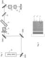
- Fig. 2 schematically illustrates the principle of a chirped mirror. To introduce negative GDD, longer wavelengths are reflected at deeper depth of the layers (in Fig. 2 , ⁇ 1 ⁇ 2 ⁇ 3 ).
- Korean Patent No. KR2015090799A describes a laser system including a laser which provides a laser pulse, a fiber for transmitting the laser pulses, a pulse stretcher between the laser and the fiber, and a pulse compressor between the fiber and a target.
- the pulse stretcher disperses the laser pulse
- the fiber extends the spectrum of the laser pulse during transmission
- the pulse compressor reduces the pulse width of the laser pulse.
- the pulse stretcher and pulse compressors each uses a pair chirped mirrors where the beam bounces between the two mirrors multiple times, or a pair of prisms, or a pair of gratings, or a pair of grisms.
- U.S. Pat. Appl. Pub. No. 20140328365 describes a femtosecond laser device in which the two end mirrors of the laser resonator are dispersive (or chirped) mirrors to produce an average negative GDD.
- the laser system also uses a GDD pre-compensation unit disposed between the laser device and the fiber transmission unit, which uses a pair of dispersive mirrors where the beam bounces between the two mirrors multiple times giving a negative dispersion between - 5000 and -15000 fs 2 .
- U.S. Pat. No. 9188776 B2 describes an ultra-short pulse laser system which includes a dispersion compensating device for compensating the GDD of other components in the system.
- the dispersion compensating device includes a deformable, dispersive (or “chirped") mirror, an actuator device for moving the dispersive mirror, and a bulk compensator.
- the bulk compensator uses a pair of oppositely disposed dispersive mirrors, where the beam bounces between the two mirrors multiple times; it may also use a single dispersive mirror, a pair of gratings or a pair of prisms.
- Korean Patent No. KR2013045245A describes a femtosecond laser with adjustable repetition rate, including a stretcher-compressor that employs a chirped volume Bragg grating which stretches the pulse entering one end of the grating and compresses the pulse entering the opposite end of the grating.
- This patent also shows a design where a laser pulse amplifier with dispersion control, where one or more of the end mirrors or folding mirrors of the resonance cavity are chirped mirrors.
- Chirped mirrors typically produce a few hundred fs 2 of negative GDD per bounce.
- P. Dombi et al. Pulse compression with time-domain optimized chirped mirrors, 26 December 2005 / Vol. 13, No. 26 / OPTICS EXPRESS 10888-10894 , describes designs of chirped mirrors compressors capable of providing peak-to-peak GDD-oscillations over 2000 fs 2 in six mirror bounces in certain wavelength ranges, for generating sub-5-fs pulses.
- Very high GDD chirped mirrors such as chirped mirrors that can provide up to -5000 fs 2 of GDD per bounce in certain wavelength range are commercially available, for example, from NANEO Precision IBS Coatings GmbH.
- the present invention is directed to an apparatus, system and related method that substantially obviates one or more of the problems due to limitations and disadvantages of the related art.
- An object of the present invention is to achieve pulse compression using chirped mirrors to provide necessary negative GDD and to eliminate mechanical movements, diffraction gratings or prisms, lenses and a complex alignment process associated with conventional pulse compressors.
- the present invention provides an optical system for directing a pulsed laser beam from a laser to an objective lens, which includes: a plurality of chirped mirrors disposed along an optical path of the pulsed laser beam; and one or more optical elements disposed along the optical path, the optical elements including one or more of: half wave plate, beam splitter, beam sampler, and X-Y beam position scanner and Z beam position scanner, wherein each of the plurality of chirped mirrors is disposed to reflect the pulsed laser beam only once along the optical path, wherein each of the plurality of chirped mirrors provides a negative group delay dispersion (GDD) per bounce to the pulsed laser beam in a defined wavelength range, and wherein the plurality of chirped mirrors provide a combined negative GDD which is approximately identical in absolute value to a combined positive GDD of the one or more optical elements and the objective lens.
- GDD group delay dispersion
- the present invention provides a pulsed laser system for ophthalmic applications, which includes: a laser generating a pulsed laser beam having a pulse width below a few hundred femtoseconds; an objective lens for directing the pulsed laser beam to a patient's eye; an optical system for directing the pulsed laser beam from the laser to the objective lens along an optical path, including: a plurality of chirped mirrors disposed along an optical path of the pulsed laser beam; and one or more optical elements disposed along the optical path, the optical elements including one or more of: half wave plate, beam splitter, beam sampler, XY beam position scanner and Z beam position scanner, wherein each of the plurality of chirped mirrors is disposed to reflect the pulsed laser beam only once along the optical path, wherein each of the plurality of chirped mirrors provides a negative group delay dispersion (GDD) per bounce to the pulsed laser beam in a defined wavelength range, and wherein the plurality of chirped mirrors provide a combined negative GDD
- the plurality of chirped mirrors consist of four chirped mirrors which provide a combined negative GDD of approximately -18,000 fs 2 in the defined wavelength range.
- Embodiments of the present invention eliminate the mechanical pulse compressor from the laser head module, and instead use chirped mirrors to provide a negative GDD to compress the laser pulses when they travel in the beam delivery system between the laser head and the objective lens that focuses the beam onto the eye.
- a number of mirrors are used to turn the beam in order to achieve a compact optical system design and/or a desired direction of the output beam.
- chirped mirrors are used in the beam delivery system to achieve the dual functions of both turning the laser beam to the appropriate directions and providing the required negative GDD to compensate for the pulse broadening.
- some or all of the beam turning mirrors in the conventional beam delivery system are replaced by chirped mirrors; additional chirped mirrors may be used as needed to provide the required amount of negative GDD.
- Each chirped mirror in the beam delivery system reflects the laser beam only once.
- the femtosecond laser system eliminates the conventional pulse compressor -- including the diffraction gratings or prisms or grisms, lenses, mirrors, and mechanical actuators -- without adding many additional optical components to the beam delivery system. This will significantly reduce the size of the laser head. Because fewer optical elements are used in the laser head, the associated alignment requirements are reduced. Further, mechanical or electrical actuators required by conventional pulse compressors are eliminated, which results in a more robust and reliable system.
- Femtosecond laser pulses transmitting through the optical components of a laser beam delivery system typically experience a positive GDD close to approximately +18,000 fs 2 in the operating wavelength range.
- Current state of the art chirped mirrors can be manufactured to provide up to -5,000 fs 2 of GDD per bounce for femtosecond laser pulses in the wavelength range of about 400 to 1500 nm.
- four such chirped mirrors are used, which replace four or two conventional turning mirrors.
- the four chirped mirrors may be one pair with approximately -5,000 fs 2 of GDD per bounce for each mirror and one pair with approximately -4,000 fs 2 of GDD per bounce for each mirror, or two pairs with approximately -4,500 fs 2 of GDD per bounce for each mirror, so that the four chirped mirrors provide a total of negative GDD of approximately -18,000 fs 2 .
- Fig. 1 schematically illustrates a femtosecond laser system including the laser beam delivery system for ophthalmic applications.
- the laser 10 is a femtosecond laser capable of generating a pulsed laser beam having a pulse width in the range of a few femtoseconds to a few hundred femtoseconds.
- the laser 10 does not include a conventional pulse compressor that employs diffraction gratings, prisms or grisms and mechanical actuators.
- the beam delivery optical system located between the laser head 10 and the objective lens 17 includes first to fourth chirped mirrors CM1, CM2, CM3 and CM4, disposed in that order in the optical path between the laser head and the objective lens, each reflecting the laser beam only once.
- a number of other optical elements of the laser beam delivery system are disposed between the first to fourth chirped mirrors CM1 to CM4.
- a half wave plate 11, a beam splitter 12, a first beam sampler 13 and a second beam sampler 14 are disposed between the third chirped mirror CM3 and the fourth chirped mirror CM4, and beam position scanners such as XY scanner 15 and Z scanner 16 are located between the fourth chirped mirror CM4 and the objective lens 17.
- the first to third chirped mirrors CM1, CM2 and CM3 are disposed upstream of the optical elements 11-14, and the fourth chirped mirror CM4 directs the laser beam from the last one of the optical elements 11-14 to the beam scanners 16 and 17 and then to the objective lens 17 to be delivered to the patient's eye.
- some of the optical components 11-14 may be disposed between the laser head 10 and the first chirped mirror CM1, or between the first and second chirped mirrors CM1 and CM2, or between the second and third chirped mirrors CM2 and CM3, or between the fourth chirped mirror CM4 and the objective lens 17.
- additional optical elements such as attenuator, beam shaping element and beam expander may be present in the laser delivery optical system and disposed along the optical path from the laser head 10 to the objective lens 17.
- Each of the four chirped mirrors CM1 to CM4 provides a GDD of approximately -4,000 to -5,000 fs 2 in a single bounce. In one implementation, each of the four chirped mirrors CM1 to CM4 provides approximately -4,500 fs 2 of GDD. Other combinations of GDD values may be used, so long as CM1 and CM2 have the same GDD and CM3 and CM4 have the same GDD and the four chirped mirrors CM1 to CM4 add up to approximately -18,000 fs 2 of GDD, which is identical in absolute value to the positive GDD of the other optical components 11-17 of the laser beam delivery system.
- each of the chirped mirrors CM1 to CM4 reflects the laser beam only once.
- the chirped mirrors CM1 to CM4 are fixedly mounted in their respective positions; i.e., they are fixed and are not moved during intended use (i.e. after they have been properly aligned). No actuators are provided to move, either to shift or to rotate, any of the chirped mirrors during intended use. Because the four chirped mirrors CM1 to CM4 provide sufficient negative GDD to compensate for the combined positive GDD of the other optical elements in the optical path, the laser beam delivery system does not include any additional diffraction pulse compressor that would employ grating pairs, prism pairs or grism pairs.
- the combined positive GDD of the other optical elements in the optical path may be a value other than +18,000 fs 2
- the negative GDD of the chirped mirrors CM1 to CM4 and the number of chirped mirrors may be selected accordingly so that the combined negative GDD of the chirped mirrors is approximately identical in absolute values to the combined positive GDD of the other optical elements.
- the GDD spectrum (i.e. the GDD curve as a function of wavelength) tends to exhibit oscillations over a relatively wide wavelength range.
- the GDD spectrum i.e. the GDD curve as a function of wavelength
- a pair of chirped mirrors are arranged in parallel to each other, and the laser beam is bounced multiple times between the two chirped mirrors.
- the first and second chirped mirrors CM1 and CM2 are designed as a pair with shifted GDD spectra
- the third and fourth chirped mirrors CM3 and CM4 are designed as a pair with shifted GDD spectra, so that the combined GDD spectrum of each pair has significantly reduced oscillations.
- the optical path is designed so that the laser beam is incident on the two chirped mirrors in each pair (CM1 and CM2, and CM3 and CM4) at identical incident angles. Note that the two chirped mirrors in each pair do not need to be parallel to each other and they are in fact not parallel to each other in the preferred embodiment.
- Chirped mirror pairs can also be designed to correct higher order dispersion effects, providing additional advantage to the beam delivery system of embodiments of the present invention which employ chirped mirror based pulse compression.
Landscapes
- Physics & Mathematics (AREA)
- Optics & Photonics (AREA)
- Health & Medical Sciences (AREA)
- Electromagnetism (AREA)
- Engineering & Computer Science (AREA)
- Ophthalmology & Optometry (AREA)
- Plasma & Fusion (AREA)
- General Physics & Mathematics (AREA)
- Vascular Medicine (AREA)
- Heart & Thoracic Surgery (AREA)
- Biomedical Technology (AREA)
- Life Sciences & Earth Sciences (AREA)
- Animal Behavior & Ethology (AREA)
- General Health & Medical Sciences (AREA)
- Public Health (AREA)
- Veterinary Medicine (AREA)
- Surgery (AREA)
- Nuclear Medicine, Radiotherapy & Molecular Imaging (AREA)
- Lasers (AREA)
- Laser Beam Processing (AREA)
Applications Claiming Priority (3)
| Application Number | Priority Date | Filing Date | Title |
|---|---|---|---|
| US201762455459P | 2017-02-06 | 2017-02-06 | |
| PCT/US2018/016922 WO2018145038A1 (en) | 2017-02-06 | 2018-02-05 | Dispersion control using chirped mirrors in femtosecond laser system for ophthalmic application |
| EP18706074.4A EP3577498B1 (de) | 2017-02-06 | 2018-02-05 | Dispersionssteuerung unter verwendung von gechirpten spiegeln in einem femtosekunden-lasersystem für ophthalmische anwendung |
Related Parent Applications (1)
| Application Number | Title | Priority Date | Filing Date |
|---|---|---|---|
| EP18706074.4A Division EP3577498B1 (de) | 2017-02-06 | 2018-02-05 | Dispersionssteuerung unter verwendung von gechirpten spiegeln in einem femtosekunden-lasersystem für ophthalmische anwendung |
Publications (2)
| Publication Number | Publication Date |
|---|---|
| EP4470514A2 true EP4470514A2 (de) | 2024-12-04 |
| EP4470514A3 EP4470514A3 (de) | 2025-04-02 |
Family
ID=61244748
Family Applications (2)
| Application Number | Title | Priority Date | Filing Date |
|---|---|---|---|
| EP18706074.4A Active EP3577498B1 (de) | 2017-02-06 | 2018-02-05 | Dispersionssteuerung unter verwendung von gechirpten spiegeln in einem femtosekunden-lasersystem für ophthalmische anwendung |
| EP24207496.1A Pending EP4470514A3 (de) | 2017-02-06 | 2018-02-05 | Dispersionssteuerung mit gechirpten spiegeln in einem femtosekundenlasersystem für ophthalmische anwendung |
Family Applications Before (1)
| Application Number | Title | Priority Date | Filing Date |
|---|---|---|---|
| EP18706074.4A Active EP3577498B1 (de) | 2017-02-06 | 2018-02-05 | Dispersionssteuerung unter verwendung von gechirpten spiegeln in einem femtosekunden-lasersystem für ophthalmische anwendung |
Country Status (5)
| Country | Link |
|---|---|
| US (1) | US10857031B2 (de) |
| EP (2) | EP3577498B1 (de) |
| AU (1) | AU2018215563A1 (de) |
| CA (1) | CA3052631A1 (de) |
| WO (1) | WO2018145038A1 (de) |
Families Citing this family (8)
| Publication number | Priority date | Publication date | Assignee | Title |
|---|---|---|---|---|
| CN110058216A (zh) * | 2019-01-25 | 2019-07-26 | 北京航天计量测试技术研究所 | 一种光路结构、光路结构的使用方法、测量系统和方法 |
| CN110058217A (zh) * | 2019-01-25 | 2019-07-26 | 北京航天计量测试技术研究所 | 一种共链路空气折射率实时补偿测距方法 |
| CN111416594B (zh) * | 2020-03-30 | 2021-10-15 | 电子科技大学 | 一种双频带负群时延电路及其参数确定方法 |
| CN111478170B (zh) * | 2020-05-15 | 2024-11-22 | 青岛自贸激光科技有限公司 | 紧凑啁啾脉冲压缩器 |
| CN111948828B (zh) * | 2020-08-25 | 2021-12-17 | 中国工程物理研究院激光聚变研究中心 | 一种无时空畸变的激光脉冲展宽方法 |
| EP4213780B1 (de) * | 2020-09-21 | 2026-04-08 | AMO Development, LLC | Mehrfach verwendbarer strahlabtaster in einem laserstrahlabgabeweg eines ophthalmischen lasersystems |
| CN115566524A (zh) * | 2022-09-06 | 2023-01-03 | 中国工程物理研究院激光聚变研究中心 | 一种超短脉冲宽度多程展宽系统及方法 |
| CN118970596B (zh) * | 2024-06-06 | 2025-11-07 | 合肥幺正量子科技有限公司 | 一种脉冲压缩器及脉冲压缩方法 |
Citations (4)
| Publication number | Priority date | Publication date | Assignee | Title |
|---|---|---|---|---|
| KR20130045245A (ko) | 2010-02-24 | 2013-05-03 | 알콘 렌즈엑스 인코포레이티드 | 조절가능한 반복률과 단순화된 구조를 가진 고출력 팸토초 레이저 |
| US20140328365A1 (en) | 2011-11-18 | 2014-11-06 | Femtolasers Produktions Gmbh | Multifunctional laser device |
| KR20150090799A (ko) | 2014-01-29 | 2015-08-06 | 한국전자통신연구원 | 레이저 시스템 |
| US9188776B2 (en) | 2013-03-15 | 2015-11-17 | Novartis Ag | System and method for scanning a beam of ultra-short pulse light |
Family Cites Families (4)
| Publication number | Priority date | Publication date | Assignee | Title |
|---|---|---|---|---|
| FR2989475B1 (fr) * | 2012-04-12 | 2014-12-05 | Amplitude Systemes | Systeme et procede d'amplification optique d'impulsions lumineuses ultra-breves au-dela de la limite de la bande spectrale de gain |
| US9240663B2 (en) * | 2013-11-14 | 2016-01-19 | Coherent, Inc. | Tunable femtosecond laser-pulse source including a super-continuum generator |
| US9438002B2 (en) * | 2014-01-29 | 2016-09-06 | Electronics And Telecommunications Research Institute | Laser system |
| EP2942847B1 (de) * | 2014-05-09 | 2019-07-03 | Max-Planck-Gesellschaft zur Förderung der Wissenschaften e.V. | Verfahren und Vorrichtung zur Erzeugung von Superkontinuum-Lichtimpulsen |
-
2018
- 2018-02-05 WO PCT/US2018/016922 patent/WO2018145038A1/en not_active Ceased
- 2018-02-05 US US15/888,997 patent/US10857031B2/en active Active
- 2018-02-05 EP EP18706074.4A patent/EP3577498B1/de active Active
- 2018-02-05 CA CA3052631A patent/CA3052631A1/en active Pending
- 2018-02-05 EP EP24207496.1A patent/EP4470514A3/de active Pending
- 2018-02-05 AU AU2018215563A patent/AU2018215563A1/en not_active Abandoned
Patent Citations (4)
| Publication number | Priority date | Publication date | Assignee | Title |
|---|---|---|---|---|
| KR20130045245A (ko) | 2010-02-24 | 2013-05-03 | 알콘 렌즈엑스 인코포레이티드 | 조절가능한 반복률과 단순화된 구조를 가진 고출력 팸토초 레이저 |
| US20140328365A1 (en) | 2011-11-18 | 2014-11-06 | Femtolasers Produktions Gmbh | Multifunctional laser device |
| US9188776B2 (en) | 2013-03-15 | 2015-11-17 | Novartis Ag | System and method for scanning a beam of ultra-short pulse light |
| KR20150090799A (ko) | 2014-01-29 | 2015-08-06 | 한국전자통신연구원 | 레이저 시스템 |
Non-Patent Citations (1)
| Title |
|---|
| P. DOMBI ET AL.: "Pulse compression with time-domain optimized chirped mirrors", OPTICS EXPRESS, vol. 13, no. 26, 26 December 2005 (2005-12-26), pages 10888 - 10894 |
Also Published As
| Publication number | Publication date |
|---|---|
| CA3052631A1 (en) | 2018-08-09 |
| US10857031B2 (en) | 2020-12-08 |
| WO2018145038A1 (en) | 2018-08-09 |
| EP4470514A3 (de) | 2025-04-02 |
| EP3577498B1 (de) | 2024-11-13 |
| AU2018215563A1 (en) | 2019-08-22 |
| EP3577498A1 (de) | 2019-12-11 |
| US20180221200A1 (en) | 2018-08-09 |
Similar Documents
| Publication | Publication Date | Title |
|---|---|---|
| EP3577498B1 (de) | Dispersionssteuerung unter verwendung von gechirpten spiegeln in einem femtosekunden-lasersystem für ophthalmische anwendung | |
| RU2589270C2 (ru) | Фемтосекундный лазер высокой мощности с регулируемой частотой повторения | |
| JP2006324613A (ja) | 受動モード同期短パルス光ファイバレーザおよびスキャニングパルスレーザ | |
| CN110573119A (zh) | 用于在光学材料中写入折射率变化的光束多路复用器 | |
| JP2019522361A (ja) | 分散調節ユニット | |
| EP2689285A1 (de) | Vorrichtung und verfahren zur aufweitung eines laserstrahls | |
| CN104040807B (zh) | 可横向调节激光束限制器 | |
| US9188776B2 (en) | System and method for scanning a beam of ultra-short pulse light | |
| KR20230122035A (ko) | 지속시간 조정형 고에너지 피코초 펄스 광섬유 레이저 시스템 및 이러한 레이저 시스템의 용도 | |
| US12263533B2 (en) | Spectrally broadening ultrashort-pulse compressor | |
| CN209561854U (zh) | 一种高重频波长可调谐的光纤飞秒激光器 | |
| CN117277027A (zh) | 一种基于不同重复频率差频的时域波长分布飞秒光源 | |
| US10566758B2 (en) | Fiber laser oscillator having thin filter reflector | |
| HK40097599A (en) | Duration-tunable high-power picosesecond pulsed optical fibre laser system and use of such laser system | |
| WO2025082979A2 (de) | Verfahren und vorrichtung zur bestrahlung eines objekts mit einem laserstrahl | |
| Li | Highly Dispersive Chirped Mirror Designs with Total Internal Reflection |
Legal Events
| Date | Code | Title | Description |
|---|---|---|---|
| PUAI | Public reference made under article 153(3) epc to a published international application that has entered the european phase |
Free format text: ORIGINAL CODE: 0009012 |
|
| STAA | Information on the status of an ep patent application or granted ep patent |
Free format text: STATUS: REQUEST FOR EXAMINATION WAS MADE |
|
| 17P | Request for examination filed |
Effective date: 20241018 |
|
| AC | Divisional application: reference to earlier application |
Ref document number: 3577498 Country of ref document: EP Kind code of ref document: P |
|
| AK | Designated contracting states |
Kind code of ref document: A2 Designated state(s): AL AT BE BG CH CY CZ DE DK EE ES FI FR GB GR HR HU IE IS IT LI LT LU LV MC MK MT NL NO PL PT RO RS SE SI SK SM TR |
|
| REG | Reference to a national code |
Ref country code: DE Ref legal event code: R079 Free format text: PREVIOUS MAIN CLASS: A61F0009008000 Ipc: G02B0005080000 |
|
| PUAL | Search report despatched |
Free format text: ORIGINAL CODE: 0009013 |
|
| AK | Designated contracting states |
Kind code of ref document: A3 Designated state(s): AL AT BE BG CH CY CZ DE DK EE ES FI FR GB GR HR HU IE IS IT LI LT LU LV MC MK MT NL NO PL PT RO RS SE SI SK SM TR |
|
| RIC1 | Information provided on ipc code assigned before grant |
Ipc: H01S 3/00 20060101ALI20250221BHEP Ipc: A61F 9/008 20060101ALI20250221BHEP Ipc: G02B 5/08 20060101AFI20250221BHEP |
|
| GRAP | Despatch of communication of intention to grant a patent |
Free format text: ORIGINAL CODE: EPIDOSNIGR1 |
|
| STAA | Information on the status of an ep patent application or granted ep patent |
Free format text: STATUS: GRANT OF PATENT IS INTENDED |
|
| RIC1 | Information provided on ipc code assigned before grant |
Ipc: G02B 5/08 20060101AFI20260319BHEP Ipc: A61F 9/008 20060101ALI20260319BHEP Ipc: H01S 3/00 20060101ALI20260319BHEP Ipc: G02B 26/10 20060101ALI20260319BHEP |