EP4470417A1 - Cosmetic applicator - Google Patents
Cosmetic applicator Download PDFInfo
- Publication number
- EP4470417A1 EP4470417A1 EP23746924.2A EP23746924A EP4470417A1 EP 4470417 A1 EP4470417 A1 EP 4470417A1 EP 23746924 A EP23746924 A EP 23746924A EP 4470417 A1 EP4470417 A1 EP 4470417A1
- Authority
- EP
- European Patent Office
- Prior art keywords
- cosmetic
- brush
- barrel
- guide
- collector
- Prior art date
- Legal status (The legal status is an assumption and is not a legal conclusion. Google has not performed a legal analysis and makes no representation as to the accuracy of the status listed.)
- Pending
Links
Images



Classifications
-
- A—HUMAN NECESSITIES
- A45—HAND OR TRAVELLING ARTICLES
- A45D—HAIRDRESSING OR SHAVING EQUIPMENT; EQUIPMENT FOR COSMETICS OR COSMETIC TREATMENTS, e.g. FOR MANICURING OR PEDICURING
- A45D34/00—Containers or accessories specially adapted for handling liquid toiletry or cosmetic substances, e.g. perfumes
- A45D34/04—Appliances specially adapted for applying liquid, e.g. using roller or ball
- A45D34/042—Appliances specially adapted for applying liquid, e.g. using roller or ball using a brush or the like
-
- A—HUMAN NECESSITIES
- A45—HAND OR TRAVELLING ARTICLES
- A45D—HAIRDRESSING OR SHAVING EQUIPMENT; EQUIPMENT FOR COSMETICS OR COSMETIC TREATMENTS, e.g. FOR MANICURING OR PEDICURING
- A45D34/00—Containers or accessories specially adapted for handling liquid toiletry or cosmetic substances, e.g. perfumes
- A45D34/04—Appliances specially adapted for applying liquid, e.g. using roller or ball
-
- A—HUMAN NECESSITIES
- A45—HAND OR TRAVELLING ARTICLES
- A45D—HAIRDRESSING OR SHAVING EQUIPMENT; EQUIPMENT FOR COSMETICS OR COSMETIC TREATMENTS, e.g. FOR MANICURING OR PEDICURING
- A45D34/00—Containers or accessories specially adapted for handling liquid toiletry or cosmetic substances, e.g. perfumes
-
- A—HUMAN NECESSITIES
- A46—BRUSHWARE
- A46B—BRUSHES
- A46B11/00—Brushes with reservoir or other means for applying substances, e.g. paints, pastes, water
- A46B11/001—Brushes with reservoir or other means for applying substances, e.g. paints, pastes, water with integral reservoirs
-
- A—HUMAN NECESSITIES
- A46—BRUSHWARE
- A46B—BRUSHES
- A46B9/00—Arrangements of the bristles in the brush body
- A46B9/02—Position or arrangement of bristles in relation to surface of the brush body, e.g. inclined, in rows, in groups
- A46B9/021—Position or arrangement of bristles in relation to surface of the brush body, e.g. inclined, in rows, in groups arranged like in cosmetics brushes, e.g. mascara, nail polish, eye shadow
-
- A—HUMAN NECESSITIES
- A46—BRUSHWARE
- A46B—BRUSHES
- A46B9/00—Arrangements of the bristles in the brush body
- A46B9/02—Position or arrangement of bristles in relation to surface of the brush body, e.g. inclined, in rows, in groups
- A46B9/026—Position or arrangement of bristles in relation to surface of the brush body, e.g. inclined, in rows, in groups where the surface of the brush body or carrier is not in one plane, e.g. not flat
-
- A—HUMAN NECESSITIES
- A61—MEDICAL OR VETERINARY SCIENCE; HYGIENE
- A61K—PREPARATIONS FOR MEDICAL, DENTAL OR TOILETRY PURPOSES
- A61K8/00—Cosmetics or similar toiletry preparations
- A61K8/02—Cosmetics or similar toiletry preparations characterised by special physical form
- A61K8/0241—Containing particulates characterized by their shape and/or structure
-
- B—PERFORMING OPERATIONS; TRANSPORTING
- B43—WRITING OR DRAWING IMPLEMENTS; BUREAU ACCESSORIES
- B43K—IMPLEMENTS FOR WRITING OR DRAWING
- B43K8/00—Pens with writing-points other than nibs or balls
- B43K8/02—Pens with writing-points other than nibs or balls with writing-points comprising fibres, felt, or similar porous or capillary material
- B43K8/022—Pens with writing-points other than nibs or balls with writing-points comprising fibres, felt, or similar porous or capillary material with writing-points comprising fibres
-
- B—PERFORMING OPERATIONS; TRANSPORTING
- B43—WRITING OR DRAWING IMPLEMENTS; BUREAU ACCESSORIES
- B43K—IMPLEMENTS FOR WRITING OR DRAWING
- B43K8/00—Pens with writing-points other than nibs or balls
- B43K8/02—Pens with writing-points other than nibs or balls with writing-points comprising fibres, felt, or similar porous or capillary material
- B43K8/04—Arrangements for feeding ink to writing-points
- B43K8/06—Wick feed from within reservoir to writing-points
- B43K8/08—Wick separate from writing-points
-
- A—HUMAN NECESSITIES
- A45—HAND OR TRAVELLING ARTICLES
- A45D—HAIRDRESSING OR SHAVING EQUIPMENT; EQUIPMENT FOR COSMETICS OR COSMETIC TREATMENTS, e.g. FOR MANICURING OR PEDICURING
- A45D2200/00—Details not otherwise provided for in A45D
- A45D2200/10—Details of applicators
-
- A—HUMAN NECESSITIES
- A46—BRUSHWARE
- A46B—BRUSHES
- A46B2200/00—Brushes characterized by their functions, uses or applications
- A46B2200/10—For human or animal care
- A46B2200/1046—Brush used for applying cosmetics
-
- B—PERFORMING OPERATIONS; TRANSPORTING
- B43—WRITING OR DRAWING IMPLEMENTS; BUREAU ACCESSORIES
- B43K—IMPLEMENTS FOR WRITING OR DRAWING
- B43K5/00—Pens with ink reservoirs in holders, e.g. fountain-pens
- B43K5/18—Arrangements for feeding the ink to the nibs
-
- B—PERFORMING OPERATIONS; TRANSPORTING
- B43—WRITING OR DRAWING IMPLEMENTS; BUREAU ACCESSORIES
- B43K—IMPLEMENTS FOR WRITING OR DRAWING
- B43K8/00—Pens with writing-points other than nibs or balls
- B43K8/02—Pens with writing-points other than nibs or balls with writing-points comprising fibres, felt, or similar porous or capillary material
- B43K8/04—Arrangements for feeding ink to writing-points
Definitions
- This disclosure relates to a cosmetic applicator for applying a cosmetic.
- Patent Documents 1 and 2 disclose an applicator having a front barrel with an application body protruding from the front end.
- the front barrel is provided with a comb-shaped collector that temporarily stores an application liquid such as a cosmetic to be supplied to the application body.
- An application liquid tank is attached to the front barrel from the rear, thus allowing the application liquid in the application liquid tank to flow to the collector and the application body.
- Patent Document 3 discloses a collector-type applicator using a color material containing tabular pigments with an average particle size of 5 to 100 ⁇ m.
- the brush of the application portion is a thin brush.
- Patent Document 3 since the brush is thin, clogging occurs easily with certain cosmetics.
- the present disclosure provides a cosmetic applicator capable of stably applying a cosmetic even when the cosmetic contains large particles.
- An embodiment of the present disclosure is a cosmetic applicator including a barrel, a brush made of bundled fibers and provided in front of the barrel, a cosmetic accommodation portion arranged in a space behind the barrel, a guide configured to guide a cosmetic from the cosmetic accommodation portion to the brush, a collector that has a comb-shaped outer circumferential surface and that is disposed inside the barrel and at an outer circumferential portion of the guide, and a front barrel supporting the brush at a front portion of the barrel, a capillary force of the guide being 50 to 200 (mm) (as measured using purified water in an environment of 25°C), and (B)/(A) being 0.8 or greater, where (A) (mg) is an amount of cosmetic liquid discharged for 1 (m), and (B) (mg) is an amount of cosmetic liquid discharged for 1 (m) after 30 (m).
- a maximum diameter of the brush excluding a flange portion is preferably 2.5 to 4 (mm)
- a ratio of a length (L1) of the brush protruding from the front barrel toward a front direction to a total length (L) of the brush, or L1/L is preferably 0.6 to 0.9
- the total length (L) of the brush is preferably 15 (mm) or less.
- a front end surface of the guide is preferably positioned in front of a front end surface of the front barrel, and a cross-sectional area of a space inside the brush is preferably 15 (%) or greater of a cross-sectional area of the brush.
- the cosmetic is preferably a combination of glitter particles having a long axis length of 10 to 30 (pm) and glitter particles having a long axis length of 50 to 80 (pm). Further, the cosmetic is preferably a liquid cosmetic having a viscosity of less than 25 (mPa ⁇ s). Note that the viscosity is a value measured at a temperature of 25°C at a predetermined shear rate (100 rpm: 383 S -1 ) using a cone-plate type viscometer (ELD type viscometer among TV-30 type viscometers, standard cone-plate, available from Tokimec Co., Ltd.).
- ELD type viscometer among TV-30 type viscometers, standard cone-plate, available from Tokimec Co., Ltd.
- the cosmetic applicator according to an embodiment of the present disclosure can exhibit an excellent effect of stably applying a cosmetic even when the cosmetic contains large particles.
- FIG.6 is an explanatory diagram of examples and comparative examples of the guide.
- the barrel 100 has a structure in which the outer barrel 12 is fitted to the outer circumference of the rear side of the front barrel 10, and a collector 16 containing a plurality of lamella portions arranged in the axial direction to form a comb shape is disposed inside the front barrel 10.
- the cosmetic accommodation portion 14 that accommodates a cosmetic is detachably installed in the outer barrel 12, as an inner barrel.
- a cap 20 is externally fitted to the front portion of the front barrel 10 to prevent the brush 18 from drying out, whereas when the cosmetic applicator is being used, the cap 20 is removed to expose the brush 18.
- the outer barrel 12 has a tubular shape with a closed tail end.
- the cosmetic accommodation portion 14 is provided inside a space of the outer barrel 12 defined by the closed tail end, the rear portion of the front barrel 10, and the rear end of the collector 16.
- An impregnation body such as an absorbent core is not disposed inside the cosmetic accommodation portion 14. Instead, a liquid cosmetic is directly accommodated in the cosmetic accommodation portion 14 (free ink type), and a stirrer 14a for stirring the application liquid is disposed in the cosmetic accommodation portion 14.
- the collector 16 is a covered structure that is positioned inside the front barrel 10 and behind the brush.
- the front barrel 10, the outer barrel 12, the cosmetic accommodation portion 14, the collector 16, the cap 20, and the like may be resin molded products. Further, the stirrer 14a may be a cylindrical material made of metal or resin. The stirrer 14a is accommodated in an accommodation space 14b inside the accommodation portion 14.
- the brush 18, which is made of a bundle of bristles having a tapered shape, protrudes from the opening 10f of a front end portion of the front barrel 10.
- the cap 20 covering the brush 18 is detachably fitted to the front barrel 10.
- the front barrel 10 has a substantially conical side shape and is tapered, and the front end angle of the front barrel 10 is preferably substantially the same angle as the front end angle of the brush 18.
- a flange 18a is formed at a rear end portion of the brush 18 with an enlarged diameter. Inside the brush 18, there is a space 18b spanning from a center portion of the flange 18a toward a front end portion of the brush 18 up to the length of approximately 2/3 or greater of the brush 18, and a front end portion 22a of the guide 22 is inserted into and present in the space 18b.
- the brush 18 is formed in a brush shape and is made of a bundle of bristles (fiber bundle) in which a large number of resin fibers or natural fiber bundles are bundled.
- the diameter of the rear end portion of the brush 18 is enlarged, forming a flange shape, which is the flange 18a containing the space 18b inside.
- the flange 18a having an enlarged diameter engages with a front end 10e1 of a rib 10e inside the front end portion of the front barrel 10 in a non-surface contact manner, and thus is prevented from falling out.
- the brush 18 is preferably a brush body, but other various brushes for applying the application liquid can be used.
- the brush 18 protrudes from the front end opening 10f, and the guide (relay core) 22 penetrates the collector 16 and extends up to the inside of the brush 18.
- a flange 10a is formed protruding in the outer radial.
- the flange 10a has a tapered front end portion and a center portion for positioning the cap 20 when the cap 20 is fitted.
- a protruding portion 10b1 for fitting the cap 20 is formed in front of the flange 10a, and two protruding portions 10b2 for fitting the outer barrel 12 are formed behind the flange 10a.
- air replacement holes 10c penetrating the circumferential surface from the inside to the outside are formed in front of the protruding portion 10b1 of the front barrel 10.
- the flange 10a is configured to have an enlarged diameter and is located in the vicinity of the center portion behind the air replacement holes (vent holes) 10c at the front end portion of the front barrel 10.
- a rear portion extends in a cylindrical shape from the flange 10a, and the protruding portions 10b2 are formed on the outer circumferential surface of the rear portion at a position about halfway into the rear portion from a rear end surface of the flange 10a.
- the protruding portions 10b2 are formed at two positions.
- a rib-like inner protrusion 10d extends in the circumferential direction is arranged in the circumferential direction at the inner circumferential surface of the tubular rear end portion of the front barrel 10, and the front barrel 10 engages with the outer circumferential surface of the cosmetic accommodation portion 14 at the inner protrusion 10d.
- a rib 10e is formed inside the front end side the front barrel 10.
- the rib 10e On the inner circumferential surface of the rear portion thereof, the rib 10e has a triangular top portion 10e1 protruding rearward. Since the brush 18 has the flange 18a, when the brush 18 is installed in the front barrel 10 during assembly, the top portion 10e1 of the rib 10e comes into contact with the flange 18a in a non-surface contact manner.
- a cup-shaped inner cap 20a that covers the brush 18 in order to enhance airtightness is arranged and is movable forward and backward, and a spring 20b is arranged to urge the inner cap 20a toward the rear.
- the guide 22 is a resin-molded core composed of a capillary member such as a resin fiber bundle, a natural fiber bundle, or a resin porous body in which a plurality of communication holes 22b are radially arranged in a cross-sectional view (see FIG.4A, FIG.4B, FIG.4C, and FIG.4D ).
- the guide 22 has the front end portion 22a (front end surface) which is formed in a tapered shape, and the communication holes 22b inside the guide 22 are exposed at the front end portion 22a.
- the front end position of the front end portion 22a substantially aligns with the position of the front end surface portion 10f1 of the front barrel 10.
- the guide 22 does not protrude into the accommodation space 14b inside the accommodation portion 14 from the rear end portion of the collector 16 (see FIG.1A, FIG.1B , FIG.2A, FIG.2B, and FIG.2C ).
- the rear end surface of the guide 22 substantially aligns with the rear end surface of the collector 16. By aligning the guide 22, the rear end of the guide 22 does not protrude into the accommodation space 14b, and the volume in the accommodation space 14b can be secured.
- the stirrer 14a since the rear end of the guide 22 does not protrude into the accommodation space 14b, when the stirrer 14a is provided in the accommodation space 14b, the stirrer 14a does not collide with the guide 22 and does not cause the guide 22 to deform even when the stirrer 14b moves inside the accommodation space 14b, thus allowing the application liquid to sufficiently penetrate.
- a bowl-shaped portion 16a is formed at the front end of the front portion of the collector 16 in the axial direction.
- a front temporary storage portion 16b and a rear temporary storage portion 16c in which a plurality of comb-shaped fins are arranged with gaps in between are formed from the front portion to the center portion in the same axial direction.
- a fin for temporarily storing the application liquid is formed by the front temporary storage portion 16b and the rear temporary storage portion 16c.
- the guide 22 is inserted into the collector 16.
- the cylindrical portion (or wall portion) 16d is formed near the axial center of the collector 16, and the guide 22 passes through the center of the cylindrical portion 16d.
- a plurality of thin plate-shaped fins (the front temporary storage portion 16b and the rear temporary storage portion 16c) for temporarily storing the application liquid are expanded in the outer diameter direction, forming a lamella.
- a longitudinal ink groove (slit) 16e that guides the application liquid into the gaps between fins is formed from the front temporary storage portion 16b to the rear temporary storage portion 16c and is exposed at the rear end portion (allowing for exposure to the accommodation space 14b of the accommodation portion 14).
- a thick support wall that abuts the inner surface of the front barrel 10 is provided between every several fins of the front temporary storage portion 16b and the rear temporary storage portion 16c, appropriately partitioning the fins.
- a maximum diameter of the brush 18 excluding the flange 18a is 2.5 to 4 (mm)
- a ratio of a length (L1) of the brush protruding from the front barrel toward a front direction to a total length (L) of the brush, or L1/L is 0.6 to 0.9
- the total length (L) of the brush is 15 (mm) or less.
- the front end portion 22a of the guide 22 is positioned in front of the front end surface portion 10f1 of the front barrel 10, and a cross-sectional area of the space 18b inside the brush 18 is 15 (%) or greater of a cross-sectional area of the brush 18.
- FIG.5A and FIG.5B compare the sizes of cosmetic applicators of a comparative example and the embodiment. Note that, in the comparative example, components similar to those in the embodiment are distinguished by adding " ' " to the same reference numerals.
- a brush 18' protrudes from an opening 10f' of a front barrel 10', and the brush 18' is covered with a cap 20' and is in a non-use state.
- a guide 22' is inserted through a collector 16' in the front barrel 10'.
- a maximum diameter ⁇ 1' of the brush 18' excluding a flange 18a' is 2.9 (mm)
- a length (L1) of the brush 18' protruding from (a front end surface portion 10f1' of) the front barrel 10' toward the front direction is 8 (mm)
- a total length (L) of the brush 18' is 16 (mm)
- a ratio of L1/L is 8/16 or 0.5.
- a space 18b' inside the brush 18' has a length of 5.4 (mm).
- the space 18b' inside the brush 18' has a maximum inside diameter of 1.2 (mm).
- the cross-sectional area of the space 18b' inside the brush 18' is 17 (%) of the cross-sectional area of the brush 18' (-8% compared to that in the example).
- the maximum diameter ⁇ 1 excluding the flange 18a of the brush 18 is 2.9 (mm)
- the length (L1) of the brush 18 protruding from (the front end surface portion 10f1 of) the front barrel 10 toward the front direction is 10 (mm)
- the total length (L) of the brush 18 is 14 (mm)
- the ratio of L1/L is 10/14 or 0.71.
- the total length (L) of the brush 18 is 14 (mm), which is 15 (mm) or less.
- the space 18b inside the brush 18 has a length of 4.6 (mm).
- the space 18b has a maximum inner diameter of 1.45 (mm).
- the cross-sectional area of the space 18b inside the brush 18 is 25 (%) of the cross-sectional area of the brush 18, which is 15 (%) or greater.
- clogging of cosmetic can be prevented by enlarging the space 18b inside the brush 18 (application portion) from the front end surface of the front barrel 10.
- the guide 22 was effective as presented in the example regardless of whether it was a molded core, such as guides a to c, or a fiber bundle.
- the guide 22 has a capillary force (as measured using purified water in an environment of 25°C) of 50 to 200 (mm).
- a capillary force as measured using purified water in an environment of 25°C
- the cosmetic includes at least glitter particles having a long axis length of 10 to 30 ( ⁇ m), glitter particles having a long axis length of 50 to 80 ( ⁇ m), and water, and has a viscosity of less than 25 (mPa ⁇ s).
- the liquid cosmetic composition in the accommodation portion 14 will be described in detail.
- the glitter particles are tabular pigments whose surfaces are coated with a compound, and examples thereof include pigment flakes such as pearl pigments, aluminum flake pigments (aluminum powder pigments), metal- or metal oxide-coated glass flakes, and aluminum-coated polyester films, as well as those obtained by coating the surfaces of the tabular pigments above with compounds such as cellulose, hemicellulose, lignin, chitin, and chitosan.
- pigment flakes such as pearl pigments, aluminum flake pigments (aluminum powder pigments), metal- or metal oxide-coated glass flakes, and aluminum-coated polyester films, as well as those obtained by coating the surfaces of the tabular pigments above with compounds such as cellulose, hemicellulose, lignin, chitin, and chitosan.
- a plurality of glitter particles such as 0.5 to 2% of the glitter particles having a long axis length of 10 to 30 ( ⁇ m) and 2 to 5% of the glitter particles having a long axis length of
- an acrylic copolymer is preferably used from the viewpoint of fixing property and dispersion stability.
- the acrylic copolymer to be used includes, for example, at least one of an alkyl acrylate copolymer, an acrylates copolymer, an acrylates copolymer ammonium, an acrylic resin alkanolamine liquid, an alkyl acrylate-vinyl acetate copolymer, an (alkyl acrylate-octylacrylamide) copolymer, a silicone-modified acrylic copolymer, or an acrylic acid octylamide-acrylic acid copolymer.
- the acrylic copolymer to be used is preferably an acrylic alkyl copolymer, an acrylates copolymer, or the like from the viewpoint of further performance and improvement of the fixing property.
- the alkyl acrylate copolymer include an (octylacrylamide/hydroxypropyl acrylate/butylaminoethyl methacrylate) copolymer (trade name "AMPHOMER”: powder) and an alkyl acrylate copolymer ammonium (trade name "YODOSOL GH800F” : solids content 45%).
- 2-amino-2-methyl-1-propanol 2-amino-2-methyl-1,3-propanediol, triethanolamine, L-arginine, aqueous ammonia, sodium hydroxide, or the like can be used, and 2-amino-2-methyl-1-propanol is particularly preferable.
- the content of these acrylic copolymers is preferably 1 to 20% in terms of solid content based on the total amount of the composition.
- the content of the acrylic copolymer is less than 1%, it is difficult for the effects of the present invention to exhibit. Meanwhile, when the content exceeds 20%, the thickening action becomes significant, and the discharge property from the application portion and good application cannot be carried out.
- the remainder of the liquid cosmetic composition is prepared with water (purified water, ion-exchanged water, distilled water, pure water, or the like) serving as a solvent.
- a humectant, an antibacterial agent, an antifoaming agent, an inorganic pigment or an organic pigment, a dye, a surfactant, a water-soluble organic solvent, and the like can be appropriately contained within a range that does not interfere with the dispersion system and does not impair the effects of the present invention.
- humectant examples include water-soluble glycols such as 1,3-butylene glycol, 1,4-butylene glycol, pentylene glycol, ethylene glycol, diethylene glycol, polyethylene glycol, propylene glycol, dipropylene glycol, and glycerin.
- the content of these humectants is preferably used in the range of 1 to 30%, more preferably 5 to 20%, with respect to the total amount of the composition.
- antibacterial agent examples include parabens, sodium dehydroacetate, phenoxyethanol, and the like.
- the antibacterial agent of the present invention includes preservatives.
- parabens which are preservatives methyl paraoxybenzoate, ethyl paraoxybenzoate, propyl paraoxybenzoate, butyl parahydroxybenzoate, isopropyl paraoxybenzoate, or the like can be used in an appropriate amount.
- antifoaming agent examples include polydimethylsiloxane (simethicone).
- This polydimethylsiloxane is a silicone oil consisting of a mixture of methylated linear siloxane polymers endblocked with trimethylsiloxy units.
- the pH of the liquid cosmetic composition is preferably in the range of 6 to 9 from the viewpoint of suppressing skin irritation.
- the pH can be adjusted using a pH adjusting agent such as 2-amino-2-methyl-1-propanol, 2-amino-2-methyl-1,3-propanediol, triethanolamine, L-arginine, aqueous ammonia, sodium hydroxide, or a citric acid solution.
- Table 1 presents an example in which the cosmetic applicator of a comparative example is compared with the cosmetic applicator of an example of the present invention in terms of the length of strokes drawn using various cosmetics accommodated in the cosmetic applicators.
- the comparative example and the example having the structures illustrated in In FIG.5A and FIG.5B were compared in terms of the distance until application became impossible when application was performed aiming for a distance of 30 (m) .
- the measurement for evaluation of application property was as follows. A cosmetic applicator was held vertically on the surface of a sheet of paper that meets JIS P3201.
- the front end (application portion) of the brush was bent to apply the cosmetic liquid contained in the cosmetic applicator clockwise at an application width of 1 to 2 mm, drawing a circle having a diameter of 30 mm at a speed of 0.4 m/min. After one circle of application, manual stirring was performed five times. The application amount was measured every 5 m, and then the application performance was evaluated after 30 m.
- the formulation of the cosmetic used is as follows. Humectant: 1.3-butylene glycol 8.0% Preservative 1.2% pH adjusting agent: 5% citric acid 0.4% Fixing agent: YODOSOL GH800F 17.2% Colored resin particles: LR-226-25 15.0% Glitter particles: Crystal SL (available from Toyo Aluminum K.K.) average particle size 20 ⁇ m 1.0% Glitter particles: Frost SL (available from Toyo Aluminum K. K.) surface-treated with crystalline cellulose [(Ceolus RC-591 (available from Asahi Kasei Corporation)] by spray drying, average particle size 64 ⁇ m 4.0% Purified water Remainder
- the "average particle size” defined in the present invention is the D50 value calculated on a volume basis using a particle size distribution analyzer HRA9320-X100 (available from Nikkiso Co., Ltd.).
- the viscosity of the cosmetic used is 4.0 mPa ⁇ s.
- FIG. 6 presents the types of guides used in the above evaluation.
- the specifications are as follows.
- the porosity was measured by immersing a guide having a known mass and apparent volume in purified water, sufficiently impregnating the guide with purified water, and then measuring the mass after taking the guide out from the purified water. From the measured mass, the volume of water impregnated in the guide was derived. Assuming that the volume of the purified water was the same as the pore volume of the guide, the porosity was calculated from the following equation.
- the applicator according to the present disclosure can be used as an applicator for an application liquid.
Landscapes
- Life Sciences & Earth Sciences (AREA)
- Health & Medical Sciences (AREA)
- Birds (AREA)
- Epidemiology (AREA)
- Animal Behavior & Ethology (AREA)
- General Health & Medical Sciences (AREA)
- Public Health (AREA)
- Veterinary Medicine (AREA)
- Coating Apparatus (AREA)
- Brushes (AREA)
Abstract


Description
- This disclosure relates to a cosmetic applicator for applying a cosmetic.
- In the related art, Patent Documents 1 and 2 disclose an applicator having a front barrel with an application body protruding from the front end. The front barrel is provided with a comb-shaped collector that temporarily stores an application liquid such as a cosmetic to be supplied to the application body. An application liquid tank is attached to the front barrel from the rear, thus allowing the application liquid in the application liquid tank to flow to the collector and the application body.
- Further, Patent Document 3 discloses a collector-type applicator using a color material containing tabular pigments with an average particle size of 5 to 100 µm. In this applicator, the brush of the application portion is a thin brush.
-
- Patent Document 1:
JP 2018-192242 A - Patent Document 2:
JP 2018-192673 A - Patent Document 3:
JP 2018-192794 A - However, in the known applicators of Patent Document 1 and Patent Document 2, clogging occurs inside the brush when certain cosmetics (glitter type) are used.
- Also in Patent Document 3, since the brush is thin, clogging occurs easily with certain cosmetics.
- In view of such circumstances, the present disclosure provides a cosmetic applicator capable of stably applying a cosmetic even when the cosmetic contains large particles.
- An embodiment of the present disclosure is a cosmetic applicator including a barrel, a brush made of bundled fibers and provided in front of the barrel, a cosmetic accommodation portion arranged in a space behind the barrel, a guide configured to guide a cosmetic from the cosmetic accommodation portion to the brush, a collector that has a comb-shaped outer circumferential surface and that is disposed inside the barrel and at an outer circumferential portion of the guide, and a front barrel supporting the brush at a front portion of the barrel, a capillary force of the guide being 50 to 200 (mm) (as measured using purified water in an environment of 25°C), and (B)/(A) being 0.8 or greater, where (A) (mg) is an amount of cosmetic liquid discharged for 1 (m), and (B) (mg) is an amount of cosmetic liquid discharged for 1 (m) after 30 (m).
- In an embodiment of the present disclosure, a maximum diameter of the brush excluding a flange portion is preferably 2.5 to 4 (mm), a ratio of a length (L1) of the brush protruding from the front barrel toward a front direction to a total length (L) of the brush, or L1/L, is preferably 0.6 to 0.9, and the total length (L) of the brush is preferably 15 (mm) or less.
- In an embodiment of the present disclosure, a front end surface of the guide is preferably positioned in front of a front end surface of the front barrel, and a cross-sectional area of a space inside the brush is preferably 15 (%) or greater of a cross-sectional area of the brush.
- In an embodiment of the present disclosure, the cosmetic is preferably a combination of glitter particles having a long axis length of 10 to 30 (pm) and glitter particles having a long axis length of 50 to 80 (pm). Further, the cosmetic is preferably a liquid cosmetic having a viscosity of less than 25 (mPa·s). Note that the viscosity is a value measured at a temperature of 25°C at a predetermined shear rate (100 rpm: 383 S-1) using a cone-plate type viscometer (ELD type viscometer among TV-30 type viscometers, standard cone-plate, available from Tokimec Co., Ltd.).
- The cosmetic applicator according to an embodiment of the present disclosure can exhibit an excellent effect of stably applying a cosmetic even when the cosmetic contains large particles.
-
-
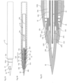
FIG.1A and FIG.1B are an explanatory diagram of a cosmetic applicator according to an embodiment of the present disclosure with a cap on, in whichFIG. 1A is an overall side view andFIG. 1B is an overall vertical cross-sectional view. -
FIG.2A, FIG.2B, and FIG.2C are an explanatory diagram of the same cosmetic applicator with the cap removed, in whichFIG.2A is an overall side view,FIG.2B is an overall vertical cross-sectional view, andFIG.2C is a detailed cross-sectional view of an area around a brush at a front portion of a front barrel. -
FIG.3A, FIG.3B, FIG.3C, FIG.3D, FIG.3E and FIG.3F are a component view of the front barrel, in whichFIG.3A is a perspective view from the front,FIG.3B is a front view,FIG.3C is a side view,FIG.3D is a vertical cross-sectional view,FIG.3E is a perspective view from the rear, andFIG.3F is a rear view. -
FIG.4A, FIG.4B, FIG.4C, and FIG.4D are a component diagram of a guide, in whichFIG. 4A is a front view,FIG. 4B is a perspective view,FIG.4C is a side view, andFIG.4D is an enlarged front view. - In
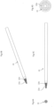
FIG.5A and FIG.5B are explanatory diagrams comparing a comparative example and an example in terms of the dimensional relationship between the front barrel and the brush. -
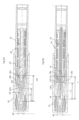
FIG.6 is an explanatory diagram of examples and comparative examples of the guide. - Embodiments of the present disclosure will be described below with reference to drawings.
-
FIG.1A and FIG.1B are an overall explanatory diagram of a cosmetic applicator according to an embodiment of the present disclosure, andFIG.2A, FIG.2B, and FIG.2C are an explanatory diagram of the cosmetic applicator with a cap removed. - As illustrated in
FIG.1A, FIG.1B ,FIG.2A, FIG.2B, and FIG.2C , the cosmetic applicator includes abarrel 100 composed of afront barrel 10 and anouter barrel 12, a brush (application body) 18 made of bundled fibers and provided in front of thebarrel 100, acosmetic accommodation portion 14 arranged in a space inside theouter barrel 12 in a portion behind thebarrel 100, aguide 22 configured to guide a cosmetic from thecosmetic accommodation portion 14 to thebrush 18, acollector 16 that has a comb-shaped outer circumferential surface and that is disposed inside thebarrel 100 and at an outer circumferential portion of theguide 22, and afront barrel 10 supporting thebrush 18 at a front portion of thebarrel 100, a capillary force of theguide 22 being 50 to 200 (mm) (as measured using purified water in an environment of 25°C), and [B]/[A] being 0.8 or greater, where (A) (mg) is an amount of cosmetic liquid discharged for 1 (m), and [B] (mg) is an amount of cosmetic liquid discharged for 1 (m) after 30 (m). - The
barrel 100 has a structure in which theouter barrel 12 is fitted to the outer circumference of the rear side of thefront barrel 10, and acollector 16 containing a plurality of lamella portions arranged in the axial direction to form a comb shape is disposed inside thefront barrel 10. - Further, in the cosmetic applicator, a rear portion of the
brush 18 is arranged inside thefront barrel 10, and a front portion of thebrush 18 is arranged to protrude from a front end opening 10f of thefront barrel 10. - The
cosmetic accommodation portion 14 that accommodates a cosmetic is detachably installed in theouter barrel 12, as an inner barrel. - The
cosmetic accommodation portion 14 is fitted into a rear portion of thefront barrel 10 and communicates with a rear portion of thecollector 16. Thecosmetic accommodation portion 14 that accommodates a cosmetic is independent from theouter barrel 12, forming a tube-in-tube structure, and the cosmetic applicator is a collector type cosmetic applicator. - Here, when the cosmetic applicator is not being used, as illustrated in
FIG.2A, FIG.2B, and FIG.2C , acap 20 is externally fitted to the front portion of thefront barrel 10 to prevent thebrush 18 from drying out, whereas when the cosmetic applicator is being used, thecap 20 is removed to expose thebrush 18. - The
outer barrel 12 has a tubular shape with a closed tail end. Thecosmetic accommodation portion 14 is provided inside a space of theouter barrel 12 defined by the closed tail end, the rear portion of thefront barrel 10, and the rear end of thecollector 16. - An impregnation body such as an absorbent core is not disposed inside the
cosmetic accommodation portion 14. Instead, a liquid cosmetic is directly accommodated in the cosmetic accommodation portion 14 (free ink type), and astirrer 14a for stirring the application liquid is disposed in thecosmetic accommodation portion 14. - The
collector 16 is a covered structure that is positioned inside thefront barrel 10 and behind the brush. - The
front barrel 10, theouter barrel 12, thecosmetic accommodation portion 14, thecollector 16, thecap 20, and the like may be resin molded products. Further, thestirrer 14a may be a cylindrical material made of metal or resin. Thestirrer 14a is accommodated in anaccommodation space 14b inside theaccommodation portion 14. - The
brush 18, which is made of a bundle of bristles having a tapered shape, protrudes from the opening 10f of a front end portion of thefront barrel 10. Thecap 20 covering thebrush 18 is detachably fitted to thefront barrel 10. Thefront barrel 10 has a substantially conical side shape and is tapered, and the front end angle of thefront barrel 10 is preferably substantially the same angle as the front end angle of thebrush 18. - A
flange 18a is formed at a rear end portion of thebrush 18 with an enlarged diameter. Inside thebrush 18, there is aspace 18b spanning from a center portion of theflange 18a toward a front end portion of thebrush 18 up to the length of approximately 2/3 or greater of thebrush 18, and afront end portion 22a of theguide 22 is inserted into and present in thespace 18b. - The
brush 18 is formed in a brush shape and is made of a bundle of bristles (fiber bundle) in which a large number of resin fibers or natural fiber bundles are bundled. The diameter of the rear end portion of thebrush 18 is enlarged, forming a flange shape, which is theflange 18a containing thespace 18b inside. Theflange 18a having an enlarged diameter engages with a front end 10e1 of arib 10e inside the front end portion of thefront barrel 10 in a non-surface contact manner, and thus is prevented from falling out. It should be noted that thebrush 18 is preferably a brush body, but other various brushes for applying the application liquid can be used. - As illustrated in
FIG.1A and FIG.1B toFIG.3A, FIG.3B, FIG.3C, FIG.3D, FIG.3E and FIG.3F , at the front of thefront barrel 10, thebrush 18 protrudes from thefront end opening 10f, and the guide (relay core) 22 penetrates thecollector 16 and extends up to the inside of thebrush 18. - At the outer circumferential surface of the
front barrel 10, aflange 10a is formed protruding in the outer radial. Theflange 10a has a tapered front end portion and a center portion for positioning thecap 20 when thecap 20 is fitted. A protruding portion 10b1 for fitting thecap 20 is formed in front of theflange 10a, and two protruding portions 10b2 for fitting theouter barrel 12 are formed behind theflange 10a. In addition, air replacement holes 10c penetrating the circumferential surface from the inside to the outside are formed in front of the protruding portion 10b1 of thefront barrel 10. - More specifically, as illustrated in
FIG.3A, FIG.3B, FIG.3C, FIG. 3D, FIG.3E and FIG. 3F , theflange 10a is configured to have an enlarged diameter and is located in the vicinity of the center portion behind the air replacement holes (vent holes) 10c at the front end portion of thefront barrel 10. A rear portion extends in a cylindrical shape from theflange 10a, and the protruding portions 10b2 are formed on the outer circumferential surface of the rear portion at a position about halfway into the rear portion from a rear end surface of theflange 10a. The protruding portions 10b2 are formed at two positions. - As illustrated in
FIG.3A, FIG.3B, FIG.3C, FIG.3D, FIG.3E and FIG.3F , a rib-likeinner protrusion 10d extends in the circumferential direction is arranged in the circumferential direction at the inner circumferential surface of the tubular rear end portion of thefront barrel 10, and thefront barrel 10 engages with the outer circumferential surface of thecosmetic accommodation portion 14 at theinner protrusion 10d. - As illustrated in
FIG.3A, FIG.3B, FIG.3C, FIG.3D, FIG.3E and FIG.3F , arib 10e is formed inside the front end side thefront barrel 10. On the inner circumferential surface of the rear portion thereof, therib 10e has a triangular top portion 10e1 protruding rearward. Since thebrush 18 has theflange 18a, when thebrush 18 is installed in thefront barrel 10 during assembly, the top portion 10e1 of therib 10e comes into contact with theflange 18a in a non-surface contact manner. - As illustrated in
FIG.1A and FIG.1B , inside thecap 20, a cup-shapedinner cap 20a that covers thebrush 18 in order to enhance airtightness is arranged and is movable forward and backward, and aspring 20b is arranged to urge theinner cap 20a toward the rear. - The
collector 16 having a bellows shape is disposed inside the hollow, taperedfront barrel 10 behind thebrush 18. Theguide 22 penetrates the inside of acylindrical portion 16d of thecollector 16. - As illustrated in
FIG.4A, FIG.4B, FIG.4C, and FIG. 4D , theguide 22 is a resin-molded core composed of a capillary member such as a resin fiber bundle, a natural fiber bundle, or a resin porous body in which a plurality ofcommunication holes 22b are radially arranged in a cross-sectional view (seeFIG.4A, FIG.4B, FIG.4C, and FIG.4D ). Theguide 22 has thefront end portion 22a (front end surface) which is formed in a tapered shape, and the communication holes 22b inside theguide 22 are exposed at thefront end portion 22a. As illustrated inFIG.2A, FIG.2B, and FIG.2C , the front end position of thefront end portion 22a substantially aligns with the position of the front end surface portion 10f1 of thefront barrel 10. - The
guide 22 does not protrude into theaccommodation space 14b inside theaccommodation portion 14 from the rear end portion of the collector 16 (seeFIG.1A, FIG.1B ,FIG.2A, FIG.2B, and FIG.2C ). The rear end surface of theguide 22 substantially aligns with the rear end surface of thecollector 16. By aligning theguide 22, the rear end of theguide 22 does not protrude into theaccommodation space 14b, and the volume in theaccommodation space 14b can be secured. In addition, since the rear end of theguide 22 does not protrude into theaccommodation space 14b, when thestirrer 14a is provided in theaccommodation space 14b, thestirrer 14a does not collide with theguide 22 and does not cause theguide 22 to deform even when thestirrer 14b moves inside theaccommodation space 14b, thus allowing the application liquid to sufficiently penetrate. - As illustrated in
FIG.1A and FIG.1B toFIG.3A, FIG.3B, FIG.3C, FIG. 3D, FIG. 3E and FIG. 3F , a bowl-shapedportion 16a is formed at the front end of the front portion of thecollector 16 in the axial direction. In thecollector 16, a fronttemporary storage portion 16b and a reartemporary storage portion 16c in which a plurality of comb-shaped fins are arranged with gaps in between are formed from the front portion to the center portion in the same axial direction. A fin for temporarily storing the application liquid is formed by the fronttemporary storage portion 16b and the reartemporary storage portion 16c. - The
guide 22 is inserted into thecollector 16. In the embodiment, the cylindrical portion (or wall portion) 16d is formed near the axial center of thecollector 16, and theguide 22 passes through the center of thecylindrical portion 16d. At the outer circumference of thecylindrical portion 16d, a plurality of thin plate-shaped fins (the fronttemporary storage portion 16b and the reartemporary storage portion 16c) for temporarily storing the application liquid are expanded in the outer diameter direction, forming a lamella. - In addition, in the
collector 16, a longitudinal ink groove (slit) 16e that guides the application liquid into the gaps between fins is formed from the fronttemporary storage portion 16b to the reartemporary storage portion 16c and is exposed at the rear end portion (allowing for exposure to theaccommodation space 14b of the accommodation portion 14). In addition, a thick support wall that abuts the inner surface of thefront barrel 10 is provided between every several fins of the fronttemporary storage portion 16b and the reartemporary storage portion 16c, appropriately partitioning the fins. - In the present embodiment, a maximum diameter of the
brush 18 excluding theflange 18a is 2.5 to 4 (mm), a ratio of a length (L1) of the brush protruding from the front barrel toward a front direction to a total length (L) of the brush, or L1/L, is 0.6 to 0.9, and the total length (L) of the brush is 15 (mm) or less. - In addition, in the cosmetic applicator, the
front end portion 22a of theguide 22 is positioned in front of the front end surface portion 10f1 of thefront barrel 10, and a cross-sectional area of thespace 18b inside thebrush 18 is 15 (%) or greater of a cross-sectional area of thebrush 18. - In
FIG.5A and FIG.5B compare the sizes of cosmetic applicators of a comparative example and the embodiment. Note that, in the comparative example, components similar to those in the embodiment are distinguished by adding " ' " to the same reference numerals. - As illustrated in
FIG.5A , in the cosmetic applicator of the comparative example, a brush 18' protrudes from anopening 10f' of a front barrel 10', and the brush 18' is covered with a cap 20' and is in a non-use state. A guide 22' is inserted through a collector 16' in the front barrel 10'. - As an example of this cosmetic applicator, a maximum diameter ϕ1' of the brush 18' excluding a
flange 18a' is 2.9 (mm), a length (L1) of the brush 18' protruding from (a front end surface portion 10f1' of) the front barrel 10' toward the front direction is 8 (mm), a total length (L) of the brush 18' is 16 (mm), and a ratio of L1/L is 8/16 or 0.5. Aspace 18b' inside the brush 18' has a length of 5.4 (mm). Thespace 18b' inside the brush 18' has a maximum inside diameter of 1.2 (mm).Cross-Sectional Area S1 of Brush 18' = (2.9/2) × (2.9/2) × π = 2.10 π Cross-Sectional Area S2 of Space 18b' Inside Brush 18' = (1.2/2) × (1.2/2) × π = 0.36 π
- Therefore, in the cosmetic applicator of the comparative example, the cross-sectional area of the
space 18b' inside the brush 18' is 17 (%) of the cross-sectional area of the brush 18' (-8% compared to that in the example). - In comparison, as an example of the cosmetic applicator of the embodiment illustrated in
FIG.5B , the maximum diameter ϕ1 excluding theflange 18a of thebrush 18 is 2.9 (mm), the length (L1) of thebrush 18 protruding from (the front end surface portion 10f1 of) thefront barrel 10 toward the front direction is 10 (mm), the total length (L) of thebrush 18 is 14 (mm), and the ratio of L1/L is 10/14 or 0.71. The total length (L) of thebrush 18 is 14 (mm), which is 15 (mm) or less. Moreover, thespace 18b inside thebrush 18 has a length of 4.6 (mm). Thespace 18b has a maximum inner diameter of 1.45 (mm).Cross-Sectional Area S1 of Brush 18 = (2.9/2) × (2.9/2) × π = 2.10 πCross-Sectional Area S2 of Space 18b Inside Brush 18 = (1.45/2) × (1.45/2) × π = 0.53 n
- Therefore, in the cosmetic applicator according to the embodiment, the cross-sectional area of the
space 18b inside thebrush 18 is 25 (%) of the cross-sectional area of thebrush 18, which is 15 (%) or greater. - In the cosmetic applicator of the embodiment, clogging of cosmetic can be prevented by enlarging the
space 18b inside the brush 18 (application portion) from the front end surface of thefront barrel 10. - As illustrated in FIG. 7, the
guide 22 was effective as presented in the example regardless of whether it was a molded core, such as guides a to c, or a fiber bundle. - The
guide 22 has a capillary force (as measured using purified water in an environment of 25°C) of 50 to 200 (mm). When the amount of cosmetic liquid discharged for 1 (m) is (A) (mg) and the amount of cosmetic liquid discharged for 1 (m) after 30 (m) is (B) (mg), (B) / (A) is 0.8 or greater. - The cosmetic includes at least glitter particles having a long axis length of 10 to 30 (µm), glitter particles having a long axis length of 50 to 80 (µm), and water, and has a viscosity of less than 25 (mPa·s).
- The liquid cosmetic composition in the
accommodation portion 14 will be described in detail. - The glitter particles are tabular pigments whose surfaces are coated with a compound, and examples thereof include pigment flakes such as pearl pigments, aluminum flake pigments (aluminum powder pigments), metal- or metal oxide-coated glass flakes, and aluminum-coated polyester films, as well as those obtained by coating the surfaces of the tabular pigments above with compounds such as cellulose, hemicellulose, lignin, chitin, and chitosan. By combining a plurality of glitter particles, such as 0.5 to 2% of the glitter particles having a long axis length of 10 to 30 (µm) and 2 to 5% of the glitter particles having a long axis length of 50 to 80 (µm), a more vivid glitter coating film is easily obtained. When the percentage is below the numerical range above, it becomes difficult to obtain sufficient glitter during coating, and when the percentage exceeds the numerical range above, evaluation of the amount of liquid discharged becomes difficult.
- In addition, an acrylic copolymer is preferably used from the viewpoint of fixing property and dispersion stability. The acrylic copolymer to be used includes, for example, at least one of an alkyl acrylate copolymer, an acrylates copolymer, an acrylates copolymer ammonium, an acrylic resin alkanolamine liquid, an alkyl acrylate-vinyl acetate copolymer, an (alkyl acrylate-octylacrylamide) copolymer, a silicone-modified acrylic copolymer, or an acrylic acid octylamide-acrylic acid copolymer.
- The acrylic copolymer to be used is preferably an acrylic alkyl copolymer, an acrylates copolymer, or the like from the viewpoint of further performance and improvement of the fixing property. Examples of the alkyl acrylate copolymer include an (octylacrylamide/hydroxypropyl acrylate/butylaminoethyl methacrylate) copolymer (trade name "AMPHOMER": powder) and an alkyl acrylate copolymer ammonium (trade name "YODOSOL GH800F" : solids content 45%).
- Note that, for neutralization, 2-amino-2-methyl-1-propanol, 2-amino-2-methyl-1,3-propanediol, triethanolamine, L-arginine, aqueous ammonia, sodium hydroxide, or the like can be used, and 2-amino-2-methyl-1-propanol is particularly preferable.
- The content of these acrylic copolymers is preferably 1 to 20% in terms of solid content based on the total amount of the composition.
- When the content of the acrylic copolymer is less than 1%, it is difficult for the effects of the present invention to exhibit. Meanwhile, when the content exceeds 20%, the thickening action becomes significant, and the discharge property from the application portion and good application cannot be carried out.
- In addition to the above ingredients, the remainder of the liquid cosmetic composition is prepared with water (purified water, ion-exchanged water, distilled water, pure water, or the like) serving as a solvent.
- Furthermore, a humectant, an antibacterial agent, an antifoaming agent, an inorganic pigment or an organic pigment, a dye, a surfactant, a water-soluble organic solvent, and the like can be appropriately contained within a range that does not interfere with the dispersion system and does not impair the effects of the present invention.
- Examples of the humectant that can be used include water-soluble glycols such as 1,3-butylene glycol, 1,4-butylene glycol, pentylene glycol, ethylene glycol, diethylene glycol, polyethylene glycol, propylene glycol, dipropylene glycol, and glycerin.
- The content of these humectants is preferably used in the range of 1 to 30%, more preferably 5 to 20%, with respect to the total amount of the composition.
- Examples of the antibacterial agent that can be used include parabens, sodium dehydroacetate, phenoxyethanol, and the like. Note that, the antibacterial agent of the present invention includes preservatives. As parabens which are preservatives, methyl paraoxybenzoate, ethyl paraoxybenzoate, propyl paraoxybenzoate, butyl parahydroxybenzoate, isopropyl paraoxybenzoate, or the like can be used in an appropriate amount.
- Examples of the antifoaming agent that can be used include polydimethylsiloxane (simethicone). This polydimethylsiloxane is a silicone oil consisting of a mixture of methylated linear siloxane polymers endblocked with trimethylsiloxy units.
- The pH of the liquid cosmetic composition is preferably in the range of 6 to 9 from the viewpoint of suppressing skin irritation. Note that, the pH can be adjusted using a pH adjusting agent such as 2-amino-2-methyl-1-propanol, 2-amino-2-methyl-1,3-propanediol, triethanolamine, L-arginine, aqueous ammonia, sodium hydroxide, or a citric acid solution.
- Table 1 presents an example in which the cosmetic applicator of a comparative example is compared with the cosmetic applicator of an example of the present invention in terms of the length of strokes drawn using various cosmetics accommodated in the cosmetic applicators. In this case, the comparative example and the example having the structures illustrated in In
FIG.5A and FIG.5B were compared in terms of the distance until application became impossible when application was performed aiming for a distance of 30 (m) . The measurement for evaluation of application property was as follows. A cosmetic applicator was held vertically on the surface of a sheet of paper that meets JIS P3201. The front end (application portion) of the brush was bent to apply the cosmetic liquid contained in the cosmetic applicator clockwise at an application width of 1 to 2 mm, drawing a circle having a diameter of 30 mm at a speed of 0.4 m/min. After one circle of application, manual stirring was performed five times. The application amount was measured every 5 m, and then the application performance was evaluated after 30 m. The evaluation criteria are based on the results of (B)/(A) as follows, where (A) (mg) is the amount of cosmetic liquid discharged for the first 1 (m) and (B) (mg) is the amount of cosmetic liquid discharged for 1 (m) after 30 (m). Note that in each example, the average value where n = 3 was used. - Evaluation A: (B)/(A) is 0.8 or greater
- Evaluation B: (B)/(A) is 0.5 or greater
- Evaluation C: (B)/(A) is less than 0.5
- The formulation of the cosmetic used is as follows.
Humectant: 1.3-butylene glycol 8.0% Preservative 1.2% pH adjusting agent: 5% citric acid 0.4% Fixing agent: YODOSOL GH800F 17.2% Colored resin particles: LR-226-25 15.0% Glitter particles: Crystal SL (available from Toyo Aluminum K.K.) average particle size 20 µm1.0% Glitter particles: Frost SL (available from Toyo Aluminum K. K.) surface-treated with crystalline cellulose [(Ceolus RC-591 (available from Asahi Kasei Corporation)] by spray drying, average particle size 64 µm 4.0% Purified water Remainder - The "average particle size" defined in the present invention is the D50 value calculated on a volume basis using a particle size distribution analyzer HRA9320-X100 (available from Nikkiso Co., Ltd.).
- The viscosity of the cosmetic used is 4.0 mPa·s.
- In all of the comparative examples, application shortage occurred before the distance reached 30 (m) (evaluated as C) . In examples 1 to 4, application reached 30 (m) and the result was good (evaluated as A).
-
FIG. 6 presents the types of guides used in the above evaluation. The specifications are as follows. - Guide a: molded core with an outer diameter ϕ of 1.8 (mm) and a capillary force of 94 (mm),
- Guide b: molded core with an outer diameter ϕ of 1.5 (mm) and a capillary force of 113 (mm),
- Guide c: fiber bundle core with an outer diameter ϕ of 2.0 (mm), a capillary force of 199 (mm), and a porosity of 61%,
- Guide d: fiber bundle with an outer diameter ϕ of 1.8 (mm), a capillary force of 218 (mm), and a porosity of 74%,
- Guide e: fiber bundle with an outer diameter ϕ of 1.5 (mm), an average capillary force of 454 (mm), and a porosity of 48%
- The capillary force was the average value of two measurements where n = 3 in each example using purified water in an environment of a temperature of 25°C and a humidity of 60%. The porosity was measured by immersing a guide having a known mass and apparent volume in purified water, sufficiently impregnating the guide with purified water, and then measuring the mass after taking the guide out from the purified water. From the measured mass, the volume of water impregnated in the guide was derived. Assuming that the volume of the purified water was the same as the pore volume of the guide, the porosity was calculated from the following equation. The opening area ratio was measured using an image taken of a radial cross section using an electron microscope.
Porosity (unit: %) = (Volume of Purified Water)/(Apparent Volume of Guide) × 100 - The above-described embodiment is an example of the present invention, and it goes without saying that modifications made within the scope of the present invention are also within the technical scope.
- The applicator according to the present disclosure can be used as an applicator for an application liquid.
-
- 10 Front Barrel
- 10f Front End Opening
- 10f1 Front End Surface Portion
- 12 Outer Barrel
- 14 Cosmetic Accommodation Portion
- 16 Collector
- 18 Brush
- 18a Flange
- 18b Space (Internal Space)
- 22 Guide
- 22a Front End Portion of Guide
- 22b Communication Hole of Guide
- 100 Barrel
| Item | Reference Sign | Example 1 | Example 2 | Example 3 | Comparative Example 1 | Comparative Example 2 | Example 4 | Example 5 | Comparative Example 3 | Comparative Example 4 | |
| | L1 | 10 | 10 | 10 | 10 | 10 | 10 | 8.5 | 6 | 6 | |
| | 16 | 14 | 14 | 16 | 14 | 16 | 14 | 14 | 14 | ||
| L1/L | 0.63 | 0.71 | 0.71 | 0.63 | 0.71 | 0.63 | 0.61 | 0.43 | 0.43 | ||
| Cross-Sectional Area | S1 | 6.60 | 6.60 | 6.60 | 6.60 | 6.60 | 6.60 | 6.60 | 6.60 | 3.80 | |
| S2 | 2.54 | 1.67 | 3.14 | 2.54 | 1.67 | 1.67 | 1.67 | 1.67 | 1.67 | ||
| S2/S1 | 0.39 | 0.25 | 0.48 | 0.39 | 0.25 | 0.25 | 0.25 | 0.25 | 0.44 | ||
| Guide | a | b | c | d | e | b | b | b | b | ||
| Amount of Cosmetic Liquid Discharged | B/A | 0.82 | 0.88 | 0.55 | 0.31 | 0.24 | 0.81 | 0.63 | 0.48 | 0.43 | |
| Evaluation Result | A | A | B | C | C | A | B | C | C |
Claims (4)
- A cosmetic applicator comprising:a barrel;a brush made of bundled fibers and provided in front of the barrel;a cosmetic accommodation portion arranged in a space behind the barrel;a guide configured to guide a cosmetic from the cosmetic accommodation portion to the brush;a collector that has a comb-shaped outer circumferential surface and that is disposed inside the barrel and at an outer circumferential portion of the guide; anda front barrel supporting the brush at a front portion of the barrel,a capillary force of the guide being 50 to 200 (mm) (as measured using purified water in an environment of 25°C), and(B)/(A) being 0.8 or greater, where (A) (mg) is an amount of cosmetic liquid discharged for 1 (m), and (B) (mg) is an amount of cosmetic liquid discharged for 1 (m) after 30 (m).
- The cosmetic applicator according to claim 1, wherein a maximum diameter of the brush excluding a flange portion is 2.5 to 4 (mm), a ratio of a length (L1) of the brush protruding from the front barrel toward a front direction to a total length (L) of the brush, or L1/L, is 0.6 to 0.9, and the total length (L) of the brush is 15 (mm) or less.
- The cosmetic applicator according to claim 1 or 2, wherein a front end surface of the guide is positioned in front of a front end surface of the front barrel, and a cross-sectional area of a space inside the brush is 15 (%) or greater of a cross-sectional area of the brush.
- The cosmetic applicator according to any one of claims 1 to 3, wherein
the cosmetic comprises at least glitter particles having a long axis length of 10 to 30 (µm),glitter particles having a long axis length of 50 to 80 (µm), andwater.
Applications Claiming Priority (2)
| Application Number | Priority Date | Filing Date | Title |
|---|---|---|---|
| JP2022009979A JP2023108760A (en) | 2022-01-26 | 2022-01-26 | cosmetic applicator |
| PCT/JP2023/002036 WO2023145713A1 (en) | 2022-01-26 | 2023-01-24 | Cosmetic applicator |
Publications (2)
| Publication Number | Publication Date |
|---|---|
| EP4470417A1 true EP4470417A1 (en) | 2024-12-04 |
| EP4470417A4 EP4470417A4 (en) | 2026-01-14 |
Family
ID=87471928
Family Applications (1)
| Application Number | Title | Priority Date | Filing Date |
|---|---|---|---|
| EP23746924.2A Pending EP4470417A4 (en) | 2022-01-26 | 2023-01-24 | COSMETIC APPLICATOR |
Country Status (6)
| Country | Link |
|---|---|
| US (1) | US12369699B2 (en) |
| EP (1) | EP4470417A4 (en) |
| JP (1) | JP2023108760A (en) |
| KR (1) | KR20240133733A (en) |
| CN (1) | CN118574543A (en) |
| WO (1) | WO2023145713A1 (en) |
Families Citing this family (2)
| Publication number | Priority date | Publication date | Assignee | Title |
|---|---|---|---|---|
| JP2025118525A (en) * | 2024-01-31 | 2025-08-13 | 三菱鉛筆株式会社 | Cosmetic applicators |
| WO2025258007A1 (en) * | 2024-06-13 | 2025-12-18 | 株式会社日本色材工業研究所 | Cosmetic container and cosmetic |
Family Cites Families (9)
| Publication number | Priority date | Publication date | Assignee | Title |
|---|---|---|---|---|
| EP1446457A1 (en) * | 2001-11-19 | 2004-08-18 | Sanford L.P. | Metallic ink and capillary marker |
| MXPA06003051A (en) * | 2003-09-19 | 2006-06-20 | Sanford Lp | Capillary action glitter markers and ink compositions for same. |
| JP4526283B2 (en) * | 2004-03-10 | 2010-08-18 | 三菱鉛筆株式会社 | Writing instrument |
| JP2008055742A (en) * | 2006-08-31 | 2008-03-13 | Pentel Corp | Brush ear |
| JP7401175B2 (en) | 2017-05-16 | 2023-12-19 | 三菱鉛筆株式会社 | applicator |
| JP7441598B2 (en) | 2017-05-16 | 2024-03-01 | 三菱鉛筆株式会社 | applicator |
| JP7085398B2 (en) | 2017-05-16 | 2022-06-16 | 三菱鉛筆株式会社 | Applying tool |
| CN113195110A (en) * | 2018-12-06 | 2021-07-30 | Teibow有限公司 | Relay core, pen tip unit, and liquid application tool |
| JP7100904B2 (en) * | 2020-01-17 | 2022-07-14 | ケミコスクリエイションズ株式会社 | Direct liquid pen type eyeliner |
-
2022
- 2022-01-26 JP JP2022009979A patent/JP2023108760A/en active Pending
-
2023
- 2023-01-24 EP EP23746924.2A patent/EP4470417A4/en active Pending
- 2023-01-24 WO PCT/JP2023/002036 patent/WO2023145713A1/en not_active Ceased
- 2023-01-24 US US18/730,766 patent/US12369699B2/en active Active
- 2023-01-24 CN CN202380017791.6A patent/CN118574543A/en active Pending
- 2023-01-24 KR KR1020247026022A patent/KR20240133733A/en active Pending
Also Published As
| Publication number | Publication date |
|---|---|
| US20250113908A1 (en) | 2025-04-10 |
| EP4470417A4 (en) | 2026-01-14 |
| JP2023108760A (en) | 2023-08-07 |
| WO2023145713A1 (en) | 2023-08-03 |
| KR20240133733A (en) | 2024-09-04 |
| US12369699B2 (en) | 2025-07-29 |
| CN118574543A (en) | 2024-08-30 |
Similar Documents
| Publication | Publication Date | Title |
|---|---|---|
| EP4470417A1 (en) | Cosmetic applicator | |
| EP3626119B1 (en) | Applicator | |
| KR102873667B1 (en) | Liquid cosmetic composition | |
| KR101612998B1 (en) | Liquid cosmetic | |
| KR100720698B1 (en) | Writing utensils | |
| EP4431158A1 (en) | Aqueous liquid cosmetic | |
| US8454981B2 (en) | Cosmetic preparation for coloring the eyelids and eyebrows | |
| JP5886020B2 (en) | Aqueous beauty nail composition | |
| JP2013124360A (en) | Water-based ink composition for writing utensil | |
| JP6549900B2 (en) | Applicator | |
| JP5705067B2 (en) | Beauty nail composition | |
| EP4681701A1 (en) | Aqueous liquid cosmetic | |
| MX2007012905A (en) | Cosmetic preparation for coloring of eyelids and eyebrows . | |
| JPH07266778A (en) | Water-based ballpoint pen | |
| EP4711424A1 (en) | Aqueous ink composition for writing utensils, and writing utensil obtained using same | |
| EP4559357A1 (en) | Cosmetic applicator | |
| TWI754055B (en) | applicator | |
| WO2015091062A1 (en) | Nail coating composition, assembly, process and use | |
| CN121866043A (en) | Aqueous liquid cosmetic | |
| JP7291486B2 (en) | Retractable padding type marking pen and core used for it | |
| KR102762784B1 (en) | Polymer combinations to improve the life of air fresheners | |
| EP4450294A1 (en) | Writing instrument | |
| JP6745387B2 (en) | Applicator | |
| JP2024151187A (en) | Water-based liquid cosmetics | |
| WO2015091063A1 (en) | Nail coating assembly and use |
Legal Events
| Date | Code | Title | Description |
|---|---|---|---|
| STAA | Information on the status of an ep patent application or granted ep patent |
Free format text: STATUS: THE INTERNATIONAL PUBLICATION HAS BEEN MADE |
|
| PUAI | Public reference made under article 153(3) epc to a published international application that has entered the european phase |
Free format text: ORIGINAL CODE: 0009012 |
|
| STAA | Information on the status of an ep patent application or granted ep patent |
Free format text: STATUS: REQUEST FOR EXAMINATION WAS MADE |
|
| 17P | Request for examination filed |
Effective date: 20240819 |
|
| AK | Designated contracting states |
Kind code of ref document: A1 Designated state(s): AL AT BE BG CH CY CZ DE DK EE ES FI FR GB GR HR HU IE IS IT LI LT LU LV MC ME MK MT NL NO PL PT RO RS SE SI SK SM TR |
|
| DAV | Request for validation of the european patent (deleted) | ||
| DAX | Request for extension of the european patent (deleted) | ||
| A4 | Supplementary search report drawn up and despatched |
Effective date: 20251217 |
|
| RIC1 | Information provided on ipc code assigned before grant |
Ipc: A45D 34/00 20060101AFI20251211BHEP Ipc: A45D 34/04 20060101ALI20251211BHEP |