EP4470356A1 - Efficient charging of an outdoor robotic work tool - Google Patents
Efficient charging of an outdoor robotic work tool Download PDFInfo
- Publication number
- EP4470356A1 EP4470356A1 EP24161739.8A EP24161739A EP4470356A1 EP 4470356 A1 EP4470356 A1 EP 4470356A1 EP 24161739 A EP24161739 A EP 24161739A EP 4470356 A1 EP4470356 A1 EP 4470356A1
- Authority
- EP
- European Patent Office
- Prior art keywords
- work tool
- power level
- robotic work
- outdoor
- charging station
- Prior art date
- Legal status (The legal status is an assumption and is not a legal conclusion. Google has not performed a legal analysis and makes no representation as to the accuracy of the status listed.)
- Pending
Links
Images




Classifications
-
- A—HUMAN NECESSITIES
- A01—AGRICULTURE; FORESTRY; ANIMAL HUSBANDRY; HUNTING; TRAPPING; FISHING
- A01D—HARVESTING; MOWING
- A01D34/00—Mowers; Mowing apparatus of harvesters
- A01D34/006—Control or measuring arrangements
- A01D34/008—Control or measuring arrangements for automated or remotely controlled operation
-
- B—PERFORMING OPERATIONS; TRANSPORTING
- B60—VEHICLES IN GENERAL
- B60L—PROPULSION OF ELECTRICALLY-PROPELLED VEHICLES; SUPPLYING ELECTRIC POWER FOR AUXILIARY EQUIPMENT OF ELECTRICALLY-PROPELLED VEHICLES; ELECTRODYNAMIC BRAKE SYSTEMS FOR VEHICLES IN GENERAL; MAGNETIC SUSPENSION OR LEVITATION FOR VEHICLES; MONITORING OPERATING VARIABLES OF ELECTRICALLY-PROPELLED VEHICLES; ELECTRIC SAFETY DEVICES FOR ELECTRICALLY-PROPELLED VEHICLES
- B60L58/00—Methods or circuit arrangements for monitoring or controlling batteries or fuel cells, specially adapted for electric vehicles
- B60L58/10—Methods or circuit arrangements for monitoring or controlling batteries or fuel cells, specially adapted for electric vehicles for monitoring or controlling batteries
- B60L58/12—Methods or circuit arrangements for monitoring or controlling batteries or fuel cells, specially adapted for electric vehicles for monitoring or controlling batteries responding to state of charge [SoC]
-
- B—PERFORMING OPERATIONS; TRANSPORTING
- B60—VEHICLES IN GENERAL
- B60L—PROPULSION OF ELECTRICALLY-PROPELLED VEHICLES; SUPPLYING ELECTRIC POWER FOR AUXILIARY EQUIPMENT OF ELECTRICALLY-PROPELLED VEHICLES; ELECTRODYNAMIC BRAKE SYSTEMS FOR VEHICLES IN GENERAL; MAGNETIC SUSPENSION OR LEVITATION FOR VEHICLES; MONITORING OPERATING VARIABLES OF ELECTRICALLY-PROPELLED VEHICLES; ELECTRIC SAFETY DEVICES FOR ELECTRICALLY-PROPELLED VEHICLES
- B60L58/00—Methods or circuit arrangements for monitoring or controlling batteries or fuel cells, specially adapted for electric vehicles
- B60L58/10—Methods or circuit arrangements for monitoring or controlling batteries or fuel cells, specially adapted for electric vehicles for monitoring or controlling batteries
- B60L58/12—Methods or circuit arrangements for monitoring or controlling batteries or fuel cells, specially adapted for electric vehicles for monitoring or controlling batteries responding to state of charge [SoC]
- B60L58/14—Preventing excessive discharging
-
- G—PHYSICS
- G05—CONTROLLING; REGULATING
- G05D—SYSTEMS FOR CONTROLLING OR REGULATING NON-ELECTRIC VARIABLES
- G05D1/00—Control of position, course, altitude or attitude of land, water, air or space vehicles, e.g. using automatic pilots
- G05D1/40—Control within particular dimensions
- G05D1/43—Control of position or course in two dimensions [2D]
-
- G—PHYSICS
- G05—CONTROLLING; REGULATING
- G05D—SYSTEMS FOR CONTROLLING OR REGULATING NON-ELECTRIC VARIABLES
- G05D1/00—Control of position, course, altitude or attitude of land, water, air or space vehicles, e.g. using automatic pilots
- G05D1/60—Intended control result
- G05D1/644—Optimisation of travel parameters, e.g. of energy consumption, journey time or distance
-
- G—PHYSICS
- G05—CONTROLLING; REGULATING
- G05D—SYSTEMS FOR CONTROLLING OR REGULATING NON-ELECTRIC VARIABLES
- G05D1/00—Control of position, course, altitude or attitude of land, water, air or space vehicles, e.g. using automatic pilots
- G05D1/60—Intended control result
- G05D1/648—Performing a task within a working area or space, e.g. cleaning
-
- B—PERFORMING OPERATIONS; TRANSPORTING
- B60—VEHICLES IN GENERAL
- B60L—PROPULSION OF ELECTRICALLY-PROPELLED VEHICLES; SUPPLYING ELECTRIC POWER FOR AUXILIARY EQUIPMENT OF ELECTRICALLY-PROPELLED VEHICLES; ELECTRODYNAMIC BRAKE SYSTEMS FOR VEHICLES IN GENERAL; MAGNETIC SUSPENSION OR LEVITATION FOR VEHICLES; MONITORING OPERATING VARIABLES OF ELECTRICALLY-PROPELLED VEHICLES; ELECTRIC SAFETY DEVICES FOR ELECTRICALLY-PROPELLED VEHICLES
- B60L2200/00—Type of vehicles
- B60L2200/40—Working vehicles
-
- B—PERFORMING OPERATIONS; TRANSPORTING
- B60—VEHICLES IN GENERAL
- B60L—PROPULSION OF ELECTRICALLY-PROPELLED VEHICLES; SUPPLYING ELECTRIC POWER FOR AUXILIARY EQUIPMENT OF ELECTRICALLY-PROPELLED VEHICLES; ELECTRODYNAMIC BRAKE SYSTEMS FOR VEHICLES IN GENERAL; MAGNETIC SUSPENSION OR LEVITATION FOR VEHICLES; MONITORING OPERATING VARIABLES OF ELECTRICALLY-PROPELLED VEHICLES; ELECTRIC SAFETY DEVICES FOR ELECTRICALLY-PROPELLED VEHICLES
- B60L2240/00—Control parameters of input or output; Target parameters
- B60L2240/40—Drive Train control parameters
- B60L2240/54—Drive Train control parameters related to batteries
-
- B—PERFORMING OPERATIONS; TRANSPORTING
- B60—VEHICLES IN GENERAL
- B60L—PROPULSION OF ELECTRICALLY-PROPELLED VEHICLES; SUPPLYING ELECTRIC POWER FOR AUXILIARY EQUIPMENT OF ELECTRICALLY-PROPELLED VEHICLES; ELECTRODYNAMIC BRAKE SYSTEMS FOR VEHICLES IN GENERAL; MAGNETIC SUSPENSION OR LEVITATION FOR VEHICLES; MONITORING OPERATING VARIABLES OF ELECTRICALLY-PROPELLED VEHICLES; ELECTRIC SAFETY DEVICES FOR ELECTRICALLY-PROPELLED VEHICLES
- B60L2240/00—Control parameters of input or output; Target parameters
- B60L2240/60—Navigation input
- B60L2240/62—Vehicle position
-
- B—PERFORMING OPERATIONS; TRANSPORTING
- B60—VEHICLES IN GENERAL
- B60L—PROPULSION OF ELECTRICALLY-PROPELLED VEHICLES; SUPPLYING ELECTRIC POWER FOR AUXILIARY EQUIPMENT OF ELECTRICALLY-PROPELLED VEHICLES; ELECTRODYNAMIC BRAKE SYSTEMS FOR VEHICLES IN GENERAL; MAGNETIC SUSPENSION OR LEVITATION FOR VEHICLES; MONITORING OPERATING VARIABLES OF ELECTRICALLY-PROPELLED VEHICLES; ELECTRIC SAFETY DEVICES FOR ELECTRICALLY-PROPELLED VEHICLES
- B60L2260/00—Operating Modes
- B60L2260/20—Drive modes; Transition between modes
- B60L2260/32—Auto pilot mode
-
- B—PERFORMING OPERATIONS; TRANSPORTING
- B60—VEHICLES IN GENERAL
- B60L—PROPULSION OF ELECTRICALLY-PROPELLED VEHICLES; SUPPLYING ELECTRIC POWER FOR AUXILIARY EQUIPMENT OF ELECTRICALLY-PROPELLED VEHICLES; ELECTRODYNAMIC BRAKE SYSTEMS FOR VEHICLES IN GENERAL; MAGNETIC SUSPENSION OR LEVITATION FOR VEHICLES; MONITORING OPERATING VARIABLES OF ELECTRICALLY-PROPELLED VEHICLES; ELECTRIC SAFETY DEVICES FOR ELECTRICALLY-PROPELLED VEHICLES
- B60L2260/00—Operating Modes
- B60L2260/40—Control modes
- B60L2260/50—Control modes by future state prediction
- B60L2260/52—Control modes by future state prediction drive range estimation, e.g. of estimation of available travel distance
-
- H—ELECTRICITY
- H02—GENERATION; CONVERSION OR DISTRIBUTION OF ELECTRIC POWER
- H02J—ELECTRIC POWER NETWORKS; CIRCUIT ARRANGEMENTS OR SYSTEMS FOR SUPPLYING OR DISTRIBUTING ELECTRIC POWER; SYSTEMS FOR STORING ELECTRIC ENERGY
- H02J7/00—Circuit arrangements for charging or discharging batteries or for supplying loads from batteries
- H02J7/80—Circuit arrangements for charging or discharging batteries or for supplying loads from batteries including monitoring or indicating arrangements
- H02J7/82—Control of state of charge [SOC]
Definitions
- the present disclosure relates to an outdoor robotic work tool system with one or more outdoor robotic work tools and work tool charging station adapted to charge a rechargeable energy storage arrangement comprised in the outdoor robotic work tool.
- Automated or robotic work tools such as robotic lawn mowers are becoming increasingly more popular.
- a work area such as a garden
- the work area can be enclosed by a boundary wire with the purpose of keeping the robotic lawn mower inside the work area.
- An electric control signal may be transmitted through the boundary wire thereby generating an (electro-) magnetic field emanating from the boundary wire.
- the robotic lawn mower is typically arranged with one or more sensors adapted to sense the control signal.
- Other types of navigation systems can be used instead of, or in combination with a boundary wire.
- Such navigation systems can for example be based on satellite navigation systems and/or local radio beacons or image processing such as Visual Simultaneous Localization and Mapping (VSLAM).
- VSLAM Visual Simultaneous Localization and Mapping
- the robotic lawn mower can then cut grass on a user's lawn automatically and can be charged automatically without intervention of the user, and no longer needs to be manually managed after being set once.
- the robotic lawn mower typically comprises charging skids for contacting corresponding contact plates in a charging station when docking into the charging station for receiving a charging current through, and possibly also for transferring information by means of electrical communication between the charging station and the robotic lawn mower.
- CN114430988 discloses comparing the remaining power of ta battery pack with the average power required to return to the charging station from the current position.
- the object of the present disclosure is to provide methods and means for efficient charging and operation of robotic work tools.
- a robotic work tool system comprising at least one outdoor robotic work tool charging station and at least one outdoor robotic work tool with a rechargeable electric power source.
- the method comprises determining a current power level for the rechargeable electric power source at a corresponding current position when the robotic work tool is operating, and determining if the rechargeable electric power source needs to be re-charged in view of at least the determined current power level. For every time that is the case, for a determined recharge power level at a corresponding recharge position where the determined recharge power level falls below a threshold power level, the method further comprises interrupting operation and controlling the outdoor robotic work tool to move to the outdoor robotic work tool charging station.
- the method Upon arrival at the outdoor robotic work tool charging station, the method comprises determining a current station power level for the rechargeable electric power source, and calculating a difference between the recharge power level and the station power level. This difference indicates the amount of power consumed for travelling between the corresponding recharge position to the outdoor robotic work tool charging station.
- the threshold power level when it has been determined suitable to control the robotic lawn mower to move to the charging station can be compared with with the current station power level such that the actual amount of power that in practice was consumed for travelling between the corresponding recharge position to the charging station can be determined.
- the method further comprises adjusting the threshold power level in view of the amount of power consumed for travelling between the corresponding recharge position and the outdoor robotic work tool charging station.
- the threshold power level can be adjusted to better reflect the actual amount of power consumed for travelling between the corresponding recharge position and the outdoor robotic work tool charging station.
- the method further comprises determining if the amount of power consumed for travelling between the corresponding recharge position and the outdoor robotic work tool charging station falls below a difference threshold power level, and if that is the case, resuming operation.
- the robotic lawn mower can be controlled to continue its cutting operation, either where it was interrupted or at another position.
- the continued cutting operation may be performed for a certain predetermined time, until a certain predetermined power level has been reached for the battery, or until predetermined amount of power has been consumed. Then the robotic lawn mower is controlled to return to the charging station.
- the method further comprises determining a current position and determining if the rechargeable electric power source needs to be re-charged in view of the determined current position, the determined current power level for the rechargeable electric power source at the determined current position, and at least one calculated amount of power consumed for travelling between a corresponding recharge position to the outdoor robotic work tool charging station.
- a current position is determined, more or less accurate, and in view of how the pre-defined operation area is configured.
- obstacles that can be in the form of hedges, fences etc., where the robotic lawn mower 100 has to be controlled to move such these obstacles are avoided. This affects the path and the distance to travel from the recharge position to the charging station and the power consumed.
- the determined current position corresponds to a predetermined zone in a predetermined work area in which the robotic work tool is arranged to operate.
- the method further comprises determining a current power level during charging, and determining the amount of power required for completing the interrupted operation.
- the method further comprises controlling the robotic lawn mower to resume operation when the determined current power level (during charging exceeds the determined amount of power required for completing the interrupted operation.
- the robotic lawnmower is controlled to resume its interrupted operation.
- This occurs can for example be determined by having knowledge of how much of the interrupted operation that remains, and where in the predetermined work area the recharge positions is located.
- the present disclosure also relates to robotic work tool systems and computer programs that are associated with the above advantages.
- FIG 1A shows a perspective view of an example robotic lawn mower 100
- Figure 1B shows a schematic overview of the robotic lawn mower 100
- the robotic lawn mower 100 is adapted for a forward travelling direction D, has a main body 140 and a plurality of wheels 130; in this example the robotic lawn mower 100 has four wheels 130, two front wheels and two rear wheels.
- the robotic lawn mower 100 comprises a work tool control unit 110 and at least one electric motor 150, where at least some of the wheels 130 are drivably connected to at least one electric motor 150.
- combustion engines may alternatively be used in combination with an electric motor arrangement.
- the robotic lawn mower 100 may be a multi-chassis type or a mono-chassis type.
- a multi-chassis type comprises two or more body parts that are movable with respect to one another.
- a mono-chassis type comprises only one main body part.
- the robotic lawn mower 100 is of a mono-chassis type, having a main body part 140.
- the main body part 140 substantially houses all components of the robotic lawn mower 100.
- the robotic lawn mower 100 also comprises a grass cutting device 160, such as a rotating blade or a disc 160 with a plurality of separate rotating blades driven by a cutter motor 165.
- the robotic lawn mower 100 also has at least one rechargeable electric power source such as a battery 155 for providing power to the electric motor arrangement 150 and/or the cutter motor 165.
- the robotic lawn mower 100 may further comprise at least one navigation arrangement 175 in a previously known manner, for example comprising a satellite navigation sensor in the form of a GPS (Global Positioning System) device or other Global Navigation Satellite System (GNSS) device, according to some aspects for example using Real Time Kinematic (RTK).
- a satellite navigation sensor in the form of a GPS (Global Positioning System) device or other Global Navigation Satellite System (GNSS) device, according to some aspects for example using Real Time Kinematic (RTK).
- GPS Global Positioning System
- GNSS Global Navigation Satellite System
- RTK Real Time Kinematic
- the robotic lawn mower 100 further comprises at least one environment detection device 170.
- radar transceivers 170 are provided and adapted to transmit signals and to receive reflected signals in a previously well-known manner.
- each radar transceiver 170 comprises a corresponding transmitter arrangement and receiver arrangement together with other necessary circuitry in a well-known manner.
- the work tool control unit 110 is adapted to control the environment detection device 170 and to control the speed and direction of the robotic lawn mower 100 in dependence of information acquired by means of the of the environment detection device 170 when the robotic lawn mower 100 is moving.
- the work tool control unit 110 is adapted to at least partly process input data from at least one environmental detection device 170.
- the environmental detector device 170 can for example comprise at least one of a radar transceiver, Lidar transceiver, ultrasonic transceiver and/or a camera device.
- the robotic lawn mower system 250 comprises the robotic lawn mower charging station 200, the robotic lawn mower 100, and a system control unit 215.
- the charging station 200 comprises a charger control unit 222 and a charging transmission arrangement 210.
- the robotic lawn mower 100 comprises a rechargeable electric power source 155 such as a battery 155, the work tool control unit 110 and a charging reception arrangement 156, such as for example charging skids, adapted for making electrical contact with the charging transmission arrangement 210 such that charging of the battery 155 is enabled.
- This means that the charging transmission arrangement 210 is adapted to transfer a charging current to the charging reception arrangement 156.
- the battery 155 is thus arranged to be charged by means of received charging current from the charging station 200, received through charging skids 156 or other suitable charging connectors that generally are constituted by the charging reception arrangement 156. Inductive charging without galvanic contact, only by means of electric contact, is also conceivable.
- the battery 155 comprises one or more batteries that can be separately arranged or be arranged in an integrated manner to form a combined battery.
- Other types of rechargeable electric power sources are conceivable such as for example power cells.
- the work tool control unit 110 is adapted to control the robotic lawn mower 100 to move within the pre-defined operation area 211.
- the pre-defined operation area 211 is for example defined by using at least one of a boundary- or guide wire 239, satellite navigation and a local radio base station 214 that is used for providing a navigation signal, e.g. UWB, Ultra Wideband).
- a navigation signal e.g. UWB, Ultra Wideband
- Other examples are VSLAM (Visual simultaneous localization and mapping), a permanent magnet, a physical barrier, and an edge detecting sensor, such as a camera or radar detecting a grass edge.
- the robotic lawn mower 100 is both shown during operation in a certain pre-defined operation area 211 and when docked to the charging station 200.
- the system control unit 215 is adapted to determine a current power level L c1 , L c2 for the battery 155 at a corresponding current position P c1 , P c2 when the robotic lawn mower 100 is operating. In Figure 3 , this is illustrated at a first current position P c1 , associated with a first current power level L c1 and a second current position P c2 associated with a second current power level L c2 . In this example, the robotic lawn mower 100 first reaches the first current position P c1 then the second current position P c2 .
- current indicates a state at a certain moment in time, at a first time there is the first current position P c1 and the first current power level L c1 , and at a subsequent second time there is the second current position P c2 and the second current power level L c2 .
- the system control unit 215 is furthermore adapted to determine if the battery 155 needs to be re-charged in view of at least the determined current power level L c1 , L c2 . For every time that is the case, for a determined recharge power level L R at a corresponding recharge position P R where the determined recharge power level L R falls below a threshold power level L T , the system control unit 215 is furthermore adapted to interrupt operation and control the robotic lawn mower 100 to move to the charging station 200.
- the system control unit 215 determines that the battery 155 needs to be re-charged. This means that in this example the second current position P c2 is the recharge position P R and the second current power level L c2 is the recharge power level L R . In other words, when the second current power level L c2 falls below the threshold power level L T , it also becomes the recharge power level L R .
- the system control unit 215 upon arrival at the charging station 200, the system control unit 215 is adapted to determine a current station power level L s for the rechargeable electric power source 155, and to calculate a difference between the recharge power level L R and the station power level L S . This difference indicates the amount of power A c consumed for travelling between the corresponding recharge position P R to the charging station 200.
- system control unit 215 can compare the threshold power level L T when it has been determined suitable to control the robotic lawn mower 100 to move to the charging station 200 with the current station power level L s and calculate the actual amount of power A c that in practice was consumed for travelling between the corresponding recharge position P R to the charging station 200.
- the system control unit 215 is adapted to adjust the threshold power level L T in view of the amount of power A c consumed for travelling between the corresponding recharge position P R and the charging station 200. This means that the threshold power level L T is determined and adjusted such that it reflects the amount of power consumed A c .
- the system control unit 215 is adapted to determine if the amount of power consumed A c for travelling between the corresponding recharge position P R and the charging station 200 falls below a difference threshold power level L TD , and if that is the case, to control the robotic lawn mower 100 to resume operation.
- the robotic lawn mower 100 can be controlled to continue its cutting operation, either where it was interrupted or at another position.
- the continued cutting operation may be performed for a certain predetermined time, until a certain predetermined power level has been reached for the battery 155, or until predetermined amount of power has been consumed. Then the robotic lawn mower 100 is controlled to return to the charging station 200.
- the above may be performed for many different types of robotic lawn mowers and robotic lawn mower systems 250, for example a robotic lawn mower system where a robotic lawn mower only is guided by means of a boundary wire 239 and not having information where within the pre-defined operation area 211 the robotic lawn mower is located.
- the current positions P c1 , P c2 are not known to the robotic lawn mower system 250, and can be anywhere in the pre-defined operation area 211.
- the present disclosure is of course also applicable for robotic lawn mower systems where robotic lawn mowers are guided more precisely as mentioned above, having more or less information regarding where in the pre-defined operation area 211 a current position P c1 , P c2 of the robotic lawn mower 100 is located. Examples of this are provided below.
- the system control unit 215 is adapted to determine a current position P c1 , P c2 and to determine S310 if the battery 155 needs to be re-charged in view of the determined current position P c1 , P c2 , the determined current power level L c1 , L c2 for the battery 155 at the determined current position P c1 , P c2 , and at least one calculated amount of power A c consumed for travelling between a corresponding recharge position P R to the charging station 200.
- the system control unit 215 is adapted to determine a current position P c1 , P c2 more or less accurate, and in view of how the pre-defined operation area 211 is configured.
- the system control unit 215 is adapted to determine a current position P c1 , P c2 more or less accurate, and in view of how the pre-defined operation area 211 is configured.
- obstacles 301, 302 may be in the form of hedges, fences etc., where the robotic lawn mower 100 has to be controlled to move such these obstacles are avoided. This affects the path 303 and the distance to travel from the recharge position P R to the charging station 200 and the power A c consumed.
- the robotic lawn mower has to travel upwards a slope 410 when moving from the recharge position P R to the charging station 200 along a path 403. Travelling upwards the slope 410 of course affects the power A c consumed.
- the need to circumvent obstacles 301, 302 and/or travelling upwards one or more slopes 410 when moving from the recharge position P R to the charging station 200 of course depends on the recharge position P R , and if the actual location of the recharge position P R is more or less known to the for robotic lawn mower system 250, different threshold power levels L T can be determined and applied for different recharge positions P R .
- the determined a current position P c1 , P c2 can be more or less accurate depending on the type of navigation arrangement 175, some examples were disclosed previously.
- the determined current position P c1 , P c2 corresponds to a predetermined zone A, B, C; A', B', C' in a predetermined work area 211 in which the robotic lawn mower 100 is arranged to operate.
- the robotic lawn mower system 250 has a more or less coarse knowledge of the actual location of the determined current position P c1 , P c2 in the predetermined work area 211.
- first predetermined zone A that is closest to the charging station 200 and defines an area that is on the same side of the obstacles 301, 302 as the charging station 200.
- second predetermined zone B that covers the obstacles 301, 302 and a third predetermined zone C that is farthest away from the charging station 200, the obstacles 301, 302 being positioned between the third predetermined zone C and the charging station 200.
- first predetermined zone A' that is closest to the charging station 200 and defines an area that is on the same side of the slope 410 as the charging station 200.
- second predetermined zone B' that covers the slope 410 and a third predetermined zone C' that is farthest away from the charging station 200, the slope 410 being positioned between the third predetermined zone C' and the charging station 200.
- the system control unit 215 is adapted to determine a a current power level L cc during charging, and to determine the amount P AC of power required for completing the interrupted operation.
- the system control unit 215 is further adapted to control the robotic lawn mower to resume operation when the determined current power level L cc during charging exceeds the determined amount P AC of power required for completing the interrupted operation.
- the robotic lawnmower is controlled to resume its interrupted operation.
- the robotic lawnmower is controlled to resume its interrupted operation.
- this occurs can for example be determined by having knowledge of how much of the interrupted operation that remains, and where in the predetermined work area 211 the recharge positions P R is located.
- the robotic lawn mower system 250 further comprises a remote server 260 that is adapted for wireless communication with at least the system control unit 215.
- the remote server can be a part of a cloud service 263 and be adapted to communicate 262 via a communications system 261.
- the present disclosure relates to a method for a robotic work tool system 250 comprising at least one outdoor robotic work tool charging station 200 and at least one outdoor robotic work tool 100 with a rechargeable electric power source 155.
- the method comprises determining S100 a current power level L c1 , L c2 for the rechargeable electric power source 155 at a corresponding current position P c1 , P c2 when the robotic work tool 100 is operating and determining S300 if the rechargeable electric power source 155 needs to be re-charged in view of at least the determined current power level L c1 , L c2 .
- the method further comprises interrupting operation and controlling S500 the outdoor robotic work tool 100 to move to the outdoor robotic work tool charging station 200, and upon arrival at the outdoor robotic work tool charging station 200, determining S600 a current station power level L s for the rechargeable electric power source 155.
- the method further comprises calculating S700 a difference between the recharge power level L R and the station power level L S , indicating the amount of power A c consumed for travelling between the corresponding recharge position P R to the outdoor robotic work tool charging station 200.
- the method further comprises adjusting S800 the threshold power level L T in view of the amount of power A c consumed for travelling between the corresponding recharge position P R and the outdoor robotic work tool charging station 200.
- the method further comprises determining if the amount of power consumed A c for travelling between the corresponding recharge position P R and the outdoor robotic work tool charging station 200 falls below a difference threshold power level L TD , and if that is the case, resuming operation.
- the method further comprises determining S200 a current position P c1 , P c2 and determining S310 if the rechargeable electric power source 155 needs to be re-charged in view of the determined current position P c1 , P c2 , the determined current power level L c1 , L c2 for the rechargeable electric power source 155 at the determined current position P c1 , P c2 , and at least one calculated amount of power A c consumed for travelling between a corresponding recharge position P R to the outdoor robotic work tool charging station 200.
- the determined current position P c1 , P c2 corresponds to a predetermined zone A, B, C; A', B', C' in a predetermined work area 211 in which the robotic work tool 100 is arranged to operate.
- the method further comprises determining a current power level L cc during charging, and determining the amount P AC of power required for completing the interrupted operation.
- the method further comprises controlling the robotic lawn mower 100 to resume operation when the determined current power level L cc during charging exceeds the determined amount P AC of power required for completing the interrupted operation.
- Processing circuitry 220 is provided using any combination of one or more of a suitable central processing unit CPU, multiprocessor, microcontroller, digital signal processor DSP, etc., capable of executing software instructions stored in a computer program product, e.g. in the form of a storage medium 230.
- the processing circuitry 220 may further be provided as at least one application specific integrated circuit ASIC, or field programmable gate array FPGA.
- the processing circuitry thus comprises a plurality of digital logic components.
- the processing circuitry 220 is configured to cause the system control unit 215 to perform a set of operations, or steps to control the charging of the robotic lawn mower 100, acquiring information and communication information in accordance with the present disclosure.
- the storage medium 230 may store the set of operations
- the processing circuitry 220 may be configured to retrieve the set of operations from the storage medium 230 to cause the system control unit 215 to perform the set of operations.
- the set of operations may be provided as a set of executable instructions.
- the processing circuitry 220 is thereby arranged to execute at least parts of the methods as herein disclosed.
- the storage medium 230 may also comprise persistent storage, which, for example, can be any single one or combination of magnetic memory, optical memory, solid state memory or even remotely mounted memory.
- the system control unit 215 further comprises an interface 240 for communications with at least one external device such as a remote server 260, a user terminal 280 and a local server 270.
- the interface 240 may comprise one or more transmitters and receivers, comprising analogue and digital components and a suitable number of ports for wireline communication.
- the interface 240 can be adapted for communication with other devices, such as the remote server 260, the charging station 200, and/or other robotic working tools. Examples of such wireless communication devices are Bluetooth ® , WiFi ® (IEEE802.11b), Global System Mobile (GSM) and LTE (Long Term Evolution), to name a few.
- Figure 6 shows a computer program product 600 comprising computer executable instructions 610 stored on media 620 to execute any of the methods disclosed herein.
- the present disclosure relates to a computer program 610 for controlling charging of a robotic lawnmower 100 in a robotic lawn mower system 250 as described herein, where the computer program 610 comprises computer code which, when run on processing circuitry 220 of a system control unit 215, causes the system control unit 215 to perform the method as described herein.
- the computer program product 500 is implemented for the system control unit 215.
- the system control unit 215 can be practically realized in many ways, for example as a single unit or being comprised in at least one of the charger control unit 222, the work tool control unit 110, the remote server 260, and the local server 270.
- the robotic lawn mower is an outdoor robotic work tool 100
- the robotic lawn mower charging station is an outdoor robotic work tool charging station 200
- the robotic lawn mower system is a robotic work tool system 250.
- the charging station can be constituted by an outdoor robotic work tool interaction station 200. Except charging, such an interaction station can be constituted by a maintenance station such as a knife sharping station, or a dumping station. The latter can for example be the case when the outdoor robotic work tool can be adapted to collect items such as leaves or golf balls. Another example of an interaction station is a marker of a lawn mower off-limit area such as an area around a plant that should be left.
- the robotic work tool system 250 may comprise one or more outdoor robotic work tool charging stations 200 and one or more outdoor robotic work tools 100.
- the present disclosure is applicable for a plurality of such systems, where charging of the outdoor robotic work tools is these systems is controlled according to the present disclosure. In this way the features of the present disclosure can be applied to all these outdoor robotic work tools.
- the system control unit 215 is adapted to control the robotic lawn mower 100 in an autonomous manner.
- a machine-learning model may be implemented, for example by means of an algorithm based on convolutional neural networks (CNN).
- CNN convolutional neural networks
- Such a machine-learning model can for example be taught to classify different objects, and to determine appropriate actions.
Landscapes
- Engineering & Computer Science (AREA)
- Life Sciences & Earth Sciences (AREA)
- Mechanical Engineering (AREA)
- Sustainable Development (AREA)
- Transportation (AREA)
- Power Engineering (AREA)
- Sustainable Energy (AREA)
- Automation & Control Theory (AREA)
- Radar, Positioning & Navigation (AREA)
- Remote Sensing (AREA)
- General Physics & Mathematics (AREA)
- Physics & Mathematics (AREA)
- Aviation & Aerospace Engineering (AREA)
- Environmental Sciences (AREA)
- Charge And Discharge Circuits For Batteries Or The Like (AREA)
- Harvester Elements (AREA)
Abstract
The present disclosure relates to a method for a robotic work tool system (250) comprising at least one outdoor robotic work tool (100) with a rechargeable battery (155). The method comprises determining (S100) a current power level (Lc1, Lc2) for the battery (155) at a corresponding current position (Pc1, Pc2) when the robotic work tool (100) is operating, and determining (S300) if the battery (155) needs to be recharged in view of at least the determined current power level (Lc1, Lc2). For every time that is the case (S400), for a determined recharge power level (LR) at a corresponding recharge position (PR) where the determined recharge power level (LR) falls below a threshold power level (LT), the method further comprises interrupting operation and controlling (S500) the outdoor robotic work tool (100) to move to an outdoor robotic work tool charging station (200). Upon arrival at the outdoor robotic work tool charging station (200), the method comprises determining (S600) a current station power level (Ls) for the battery (155), and calculating (S700) a difference between the recharge power level (LR) and the station power level (Ls).
Description
- The present disclosure relates to an outdoor robotic work tool system with one or more outdoor robotic work tools and work tool charging station adapted to charge a rechargeable energy storage arrangement comprised in the outdoor robotic work tool.
- Automated or robotic work tools such as robotic lawn mowers are becoming increasingly more popular. In a typical deployment a work area, such as a garden, the work area can be enclosed by a boundary wire with the purpose of keeping the robotic lawn mower inside the work area. An electric control signal may be transmitted through the boundary wire thereby generating an (electro-) magnetic field emanating from the boundary wire. The robotic lawn mower is typically arranged with one or more sensors adapted to sense the control signal. Other types of navigation systems can be used instead of, or in combination with a boundary wire. Such navigation systems can for example be based on satellite navigation systems and/or local radio beacons or image processing such as Visual Simultaneous Localization and Mapping (VSLAM).
- The robotic lawn mower can then cut grass on a user's lawn automatically and can be charged automatically without intervention of the user, and no longer needs to be manually managed after being set once. The robotic lawn mower typically comprises charging skids for contacting corresponding contact plates in a charging station when docking into the charging station for receiving a charging current through, and possibly also for transferring information by means of electrical communication between the charging station and the robotic lawn mower.
- Normally there is a fixed setting where robotic lawn mower is controlled to return to the charging station when it reaches a fixed charge lever.
CN114430988 discloses comparing the remaining power of ta battery pack with the average power required to return to the charging station from the current position. - There is, however, a need to provide even more improved methods and means for efficient charging and operation of robotic work tools.
- The object of the present disclosure is to provide methods and means for efficient charging and operation of robotic work tools.
- This object is achieved by means of method for a robotic work tool system comprising at least one outdoor robotic work tool charging station and at least one outdoor robotic work tool with a rechargeable electric power source. The method comprises determining a current power level for the rechargeable electric power source at a corresponding current position when the robotic work tool is operating, and determining if the rechargeable electric power source needs to be re-charged in view of at least the determined current power level. For every time that is the case, for a determined recharge power level at a corresponding recharge position where the determined recharge power level falls below a threshold power level, the method further comprises interrupting operation and controlling the outdoor robotic work tool to move to the outdoor robotic work tool charging station. Upon arrival at the outdoor robotic work tool charging station, the method comprises determining a current station power level for the rechargeable electric power source, and calculating a difference between the recharge power level and the station power level. This difference indicates the amount of power consumed for travelling between the corresponding recharge position to the outdoor robotic work tool charging station.
- This means that the threshold power level when it has been determined suitable to control the robotic lawn mower to move to the charging station can be compared with with the current station power level such that the actual amount of power that in practice was consumed for travelling between the corresponding recharge position to the charging station can be determined. With this knowledge, different actions can be taken depending on requirements and circumstances, enabling an improved efficiency for charging and operation of robotic lawn mowers.
- According to some aspects, the method further comprises adjusting the threshold power level in view of the amount of power consumed for travelling between the corresponding recharge position and the outdoor robotic work tool charging station.
- This means that the threshold power level can be adjusted to better reflect the actual amount of power consumed for travelling between the corresponding recharge position and the outdoor robotic work tool charging station.
- According to some aspects, the method further comprises determining if the amount of power consumed for travelling between the corresponding recharge position and the outdoor robotic work tool charging station falls below a difference threshold power level, and if that is the case, resuming operation.
- This means that if a sufficiently small amount of power has been consumed when travelling between the corresponding recharge position and the charging station, the robotic lawn mower can be controlled to continue its cutting operation, either where it was interrupted or at another position. The continued cutting operation may be performed for a certain predetermined time, until a certain predetermined power level has been reached for the battery, or until predetermined amount of power has been consumed. Then the robotic lawn mower is controlled to return to the charging station.
- According to some aspects, the method further comprises determining a current position and determining if the rechargeable electric power source needs to be re-charged in view of the determined current position, the determined current power level for the rechargeable electric power source at the determined current position, and at least one calculated amount of power consumed for travelling between a corresponding recharge position to the outdoor robotic work tool charging station.
- Here a current position is determined, more or less accurate, and in view of how the pre-defined operation area is configured. For example, there may be obstacles that can be in the form of hedges, fences etc., where the
robotic lawn mower 100 has to be controlled to move such these obstacles are avoided. This affects the path and the distance to travel from the recharge position to the charging station and the power consumed. - According to some aspects, the determined current position corresponds to a predetermined zone in a predetermined work area in which the robotic work tool is arranged to operate.
- This means that the knowledge about the actual location of the determined current position in the predetermined work area can be more or less coarse. The more predetermined zones, the more accurately the robotic lawn mower can be located within the predetermined work area.
- According to some aspects, the method further comprises determining a current power level during charging, and determining the amount of power required for completing the interrupted operation. The method further comprises controlling the robotic lawn mower to resume operation when the determined current power level (during charging exceeds the determined amount of power required for completing the interrupted operation.
- This means that as soon as the battery is sufficiently charged, the robotic lawnmower is controlled to resume its interrupted operation. When this occurs can for example be determined by having knowledge of how much of the interrupted operation that remains, and where in the predetermined work area the recharge positions is located.
- The present disclosure also relates to robotic work tool systems and computer programs that are associated with the above advantages.
- The present disclosure will now be described more in detail with reference to the appended drawings, where:
- Figure 1A
- shows a perspective side view of a robotic lawn mower;
- Figure 1B
- shows a schematic overview of the robotic lawn mower;
- Figure 2A
- shows a schematic side view of a charging station with a robotic lawn mower;
- Figure 2B
- shows a schematic top view of
Figure 2A ; - Figure 3
- shows a schematic illustration of a robotic work tool system and a robotic work tool travelling to a charging station;
- Figure 4
- shows a schematic side view of a robotic work tool travelling to a charging station;
- Figure 5
- shows a schematic illustration of a system control unit;
- Figure 6
- shows a schematic illustration of a computer program product; and
- Figure 7
- shows a flowchart for methods according to the present disclosure.
- Aspects of the present disclosure will now be described more fully hereinafter with reference to the accompanying drawings. The different devices, systems, computer programs and methods disclosed herein can, however, be realized in many different forms and should not be construed as being limited to the aspects set forth herein. Like numbers in the drawings refer to like elements throughout.
- The terminology used herein is for describing aspects of the disclosure only and is not intended to limit the invention. As used herein, the singular forms "a", "an" and "the" are intended to include the plural forms as well, unless the context clearly indicates otherwise.
- It should be noted that even though the description given herein will be focused on robotic lawn mowers, the teachings herein may also be applied to any type of outdoor robotic work tool, such as for example robotic ball collectors, robotic mine sweepers and robotic farming equipment.
-
Figure 1A shows a perspective view of an examplerobotic lawn mower 100 andFigure 1B shows a schematic overview of therobotic lawn mower 100. According to some aspects, therobotic lawn mower 100 is adapted for a forward travelling direction D, has amain body 140 and a plurality ofwheels 130; in this example therobotic lawn mower 100 has fourwheels 130, two front wheels and two rear wheels. Therobotic lawn mower 100 comprises a worktool control unit 110 and at least oneelectric motor 150, where at least some of thewheels 130 are drivably connected to at least oneelectric motor 150. It should be noted that even if the description herein is focused on electric motors, combustion engines may alternatively be used in combination with an electric motor arrangement. Therobotic lawn mower 100 may be a multi-chassis type or a mono-chassis type. A multi-chassis type comprises two or more body parts that are movable with respect to one another. A mono-chassis type comprises only one main body part. - In this example embodiment, the
robotic lawn mower 100 is of a mono-chassis type, having amain body part 140. Themain body part 140 substantially houses all components of therobotic lawn mower 100. - The
robotic lawn mower 100 also comprises agrass cutting device 160, such as a rotating blade or adisc 160 with a plurality of separate rotating blades driven by acutter motor 165. Therobotic lawn mower 100 also has at least one rechargeable electric power source such as abattery 155 for providing power to theelectric motor arrangement 150 and/or thecutter motor 165. - According to some aspects, the
robotic lawn mower 100 may further comprise at least onenavigation arrangement 175 in a previously known manner, for example comprising a satellite navigation sensor in the form of a GPS (Global Positioning System) device or other Global Navigation Satellite System (GNSS) device, according to some aspects for example using Real Time Kinematic (RTK). - According to some aspects, the
robotic lawn mower 100 further comprises at least oneenvironment detection device 170. In this example,radar transceivers 170 are provided and adapted to transmit signals and to receive reflected signals in a previously well-known manner. To enable this, according to some aspects, eachradar transceiver 170 comprises a corresponding transmitter arrangement and receiver arrangement together with other necessary circuitry in a well-known manner. - For this purpose, the work
tool control unit 110 is adapted to control theenvironment detection device 170 and to control the speed and direction of therobotic lawn mower 100 in dependence of information acquired by means of the of theenvironment detection device 170 when therobotic lawn mower 100 is moving. - Generally, the work
tool control unit 110 is adapted to at least partly process input data from at least oneenvironmental detection device 170. Theenvironmental detector device 170 can for example comprise at least one of a radar transceiver, Lidar transceiver, ultrasonic transceiver and/or a camera device. - With reference to
Figure 2A and Figure 2B that show a side view and a corresponding top view of a robotic lawnmower charging station 200 and therobotic lawn mower 100, andFigure 3 that shows a roboticlawn mower system 250, the roboticlawn mower system 250 comprises the robotic lawnmower charging station 200, therobotic lawn mower 100, and asystem control unit 215. The chargingstation 200 comprises acharger control unit 222 and a chargingtransmission arrangement 210. Therobotic lawn mower 100 comprises a rechargeableelectric power source 155 such as abattery 155, the worktool control unit 110 and acharging reception arrangement 156, such as for example charging skids, adapted for making electrical contact with the chargingtransmission arrangement 210 such that charging of thebattery 155 is enabled. This means that the chargingtransmission arrangement 210 is adapted to transfer a charging current to the chargingreception arrangement 156. - The
battery 155 is thus arranged to be charged by means of received charging current from the chargingstation 200, received through chargingskids 156 or other suitable charging connectors that generally are constituted by the chargingreception arrangement 156. Inductive charging without galvanic contact, only by means of electric contact, is also conceivable. According to some aspects, thebattery 155 comprises one or more batteries that can be separately arranged or be arranged in an integrated manner to form a combined battery. Other types of rechargeable electric power sources are conceivable such as for example power cells. - According to some aspects, as shown in
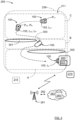
Figure 3 , the worktool control unit 110 is adapted to control therobotic lawn mower 100 to move within thepre-defined operation area 211. Thepre-defined operation area 211 is for example defined by using at least one of a boundary- orguide wire 239, satellite navigation and a local radio base station 214 that is used for providing a navigation signal, e.g. UWB, Ultra Wideband). Other examples are VSLAM (Visual simultaneous localization and mapping), a permanent magnet, a physical barrier, and an edge detecting sensor, such as a camera or radar detecting a grass edge. InFigure 3 , therobotic lawn mower 100 is both shown during operation in a certainpre-defined operation area 211 and when docked to the chargingstation 200. - The
system control unit 215 is adapted to determine a current power level Lc1, Lc2 for thebattery 155 at a corresponding current position Pc1, Pc2 when therobotic lawn mower 100 is operating. InFigure 3 , this is illustrated at a first current position Pc1, associated with a first current power level Lc1 and a second current position Pc2 associated with a second current power level Lc2. In this example, therobotic lawn mower 100 first reaches the first current position Pc1 then the second current position Pc2. The term "current" indicates a state at a certain moment in time, at a first time there is the first current position Pc1 and the first current power level Lc1, and at a subsequent second time there is the second current position Pc2 and the second current power level Lc2. - The
system control unit 215 is furthermore adapted to determine if thebattery 155 needs to be re-charged in view of at least the determined current power level Lc1, Lc2. For every time that is the case, for a determined recharge power level LR at a corresponding recharge position PR where the determined recharge power level LR falls below a threshold power level LT, thesystem control unit 215 is furthermore adapted to interrupt operation and control therobotic lawn mower 100 to move to the chargingstation 200. - In the example illustrated in
Figure 3 , at the second current position Pc2 that is associated with the second current power level Lc2, thesystem control unit 215 determines that thebattery 155 needs to be re-charged. This means that in this example the second current position Pc2 is the recharge position PR and the second current power level Lc2 is the recharge power level LR. In other words, when the second current power level Lc2 falls below the threshold power level LT, it also becomes the recharge power level LR. - According to the present disclosure, upon arrival at the charging
station 200, thesystem control unit 215 is adapted to determine a current station power level Ls for the rechargeableelectric power source 155, and to calculate a difference between the recharge power level LR and the station power level LS. This difference indicates the amount of power Ac consumed for travelling between the corresponding recharge position PR to the chargingstation 200. - This means that the
system control unit 215 can compare the threshold power level LT when it has been determined suitable to control therobotic lawn mower 100 to move to the chargingstation 200 with the current station power level Ls and calculate the actual amount of power Ac that in practice was consumed for travelling between the corresponding recharge position PR to the chargingstation 200. With this knowledge, different actions can be taken depending on requirements and circumstances, enabling an improved efficiency for charging and operation of robotic lawn mowers. - According to some aspects, the
system control unit 215 is adapted to adjust the threshold power level LT in view of the amount of power Ac consumed for travelling between the corresponding recharge position PR and the chargingstation 200. This means that the threshold power level LT is determined and adjusted such that it reflects the amount of power consumed Ac. - According to some aspects, the
system control unit 215 is adapted to determine if the amount of power consumed Ac for travelling between the corresponding recharge position PR and the chargingstation 200 falls below a difference threshold power level LTD, and if that is the case, to control therobotic lawn mower 100 to resume operation. - This means that if a sufficiently small amount of power Ac has been consumed when travelling between the corresponding recharge position PR and the charging
station 200, therobotic lawn mower 100 can be controlled to continue its cutting operation, either where it was interrupted or at another position. The continued cutting operation may be performed for a certain predetermined time, until a certain predetermined power level has been reached for thebattery 155, or until predetermined amount of power has been consumed. Then therobotic lawn mower 100 is controlled to return to the chargingstation 200. - The above may be performed for many different types of robotic lawn mowers and robotic
lawn mower systems 250, for example a robotic lawn mower system where a robotic lawn mower only is guided by means of aboundary wire 239 and not having information where within thepre-defined operation area 211 the robotic lawn mower is located. In that case, the current positions Pc1, Pc2 are not known to the roboticlawn mower system 250, and can be anywhere in thepre-defined operation area 211. - On the other hand, the present disclosure is of course also applicable for robotic lawn mower systems where robotic lawn mowers are guided more precisely as mentioned above, having more or less information regarding where in the pre-defined operation area 211 a current position Pc1, Pc2 of the
robotic lawn mower 100 is located. Examples of this are provided below. - According to some aspects, the
system control unit 215 is adapted to determine a current position Pc1, Pc2 and to determine S310 if thebattery 155 needs to be re-charged in view of the determined current position Pc1, Pc2, the determined current power level Lc1, Lc2 for thebattery 155 at the determined current position Pc1, Pc2, and at least one calculated amount of power Ac consumed for travelling between a corresponding recharge position PR to the chargingstation 200. - Here, the
system control unit 215 is adapted to determine a current position Pc1, Pc2 more or less accurate, and in view of how thepre-defined operation area 211 is configured. For example, as shown inFigure 3 there areobstacles robotic lawn mower 100 has to be controlled to move such these obstacles are avoided. This affects thepath 303 and the distance to travel from the recharge position PR to the chargingstation 200 and the power Ac consumed. - As indicated in
Figure 4 , where he second current position Pc2 is the recharge position PR and the second current power level Lc2 is the recharge power level LR, the robotic lawn mower has to travel upwards aslope 410 when moving from the recharge position PR to the chargingstation 200 along apath 403. Travelling upwards theslope 410 of course affects the power Ac consumed. - The need to circumvent
obstacles more slopes 410 when moving from the recharge position PR to the chargingstation 200 of course depends on the recharge position PR, and if the actual location of the recharge position PR is more or less known to the for roboticlawn mower system 250, different threshold power levels LT can be determined and applied for different recharge positions PR. - The determined a current position Pc1, Pc2 can be more or less accurate depending on the type of
navigation arrangement 175, some examples were disclosed previously. - According to some aspects, the determined current position Pc1, Pc2 corresponds to a predetermined zone A, B, C; A', B', C' in a
predetermined work area 211 in which therobotic lawn mower 100 is arranged to operate. This means that the roboticlawn mower system 250 has a more or less coarse knowledge of the actual location of the determined current position Pc1, Pc2 in thepredetermined work area 211. The more predetermined zones A, B, C; A', B', C', the more accurately the robotic lawn mower can be located within thepredetermined work area 211. - In the example illustrated in
Figure 3 , there is a first predetermined zone A that is closest to the chargingstation 200 and defines an area that is on the same side of theobstacles station 200. There is also a second predetermined zone B that covers theobstacles station 200, theobstacles station 200. - In the example illustrated in
Figure 4 , there is a first predetermined zone A' that is closest to the chargingstation 200 and defines an area that is on the same side of theslope 410 as the chargingstation 200. There is also a second predetermined zone B' that covers theslope 410 and a third predetermined zone C' that is farthest away from the chargingstation 200, theslope 410 being positioned between the third predetermined zone C' and the chargingstation 200. - It is clear that having knowledge of in which predetermined zone A, B, C; A', B', C' the recharge position PR is located, different threshold power levels LT can be determined and applied.
- According to some aspects, the
system control unit 215 is adapted to determine a a current power level Lcc during charging, and to determine the amount PAC of power required for completing the interrupted operation. Thesystem control unit 215 is further adapted to control the robotic lawn mower to resume operation when the determined current power level Lcc during charging exceeds the determined amount PAC of power required for completing the interrupted operation. - This means that as soon as the
battery 155 is sufficiently charged, the robotic lawnmower is controlled to resume its interrupted operation. When this occurs can for example be determined by having knowledge of how much of the interrupted operation that remains, and where in thepredetermined work area 211 the recharge positions PR is located. - According to some aspects, the robotic
lawn mower system 250 further comprises aremote server 260 that is adapted for wireless communication with at least thesystem control unit 215. According to some aspects, the remote server can be a part of acloud service 263 and be adapted to communicate 262 via acommunications system 261. - With reference to
Figure 7 , the present disclosure relates to a method for a roboticwork tool system 250 comprising at least one outdoor robotic worktool charging station 200 and at least one outdoorrobotic work tool 100 with a rechargeableelectric power source 155. The method comprises determining S100 a current power level Lc1, Lc2 for the rechargeableelectric power source 155 at a corresponding current position Pc1, Pc2 when therobotic work tool 100 is operating and determining S300 if the rechargeableelectric power source 155 needs to be re-charged in view of at least the determined current power level Lc1, Lc2. For every time that is the case S400, for a determined recharge power level LR at a corresponding recharge position PR where the determined recharge power level LR falls below a threshold power level LT, the method further comprises interrupting operation and controlling S500 the outdoorrobotic work tool 100 to move to the outdoor robotic worktool charging station 200, and upon arrival at the outdoor robotic worktool charging station 200, determining S600 a current station power level Ls for the rechargeableelectric power source 155. The method further comprises calculating S700 a difference between the recharge power level LR and the station power level LS, indicating the amount of power Ac consumed for travelling between the corresponding recharge position PR to the outdoor robotic worktool charging station 200. - According to some aspects, the method further comprises adjusting S800 the threshold power level LT in view of the amount of power Ac consumed for travelling between the corresponding recharge position PR and the outdoor robotic work
tool charging station 200. - According to some aspects, the method further comprises determining if the amount of power consumed Ac for travelling between the corresponding recharge position PR and the outdoor robotic work
tool charging station 200 falls below a difference threshold power level LTD, and if that is the case, resuming operation. - According to some aspects, the method further comprises determining S200 a current position Pc1, Pc2 and determining S310 if the rechargeable
electric power source 155 needs to be re-charged in view of the determined current position Pc1, Pc2, the determined current power level Lc1, Lc2 for the rechargeableelectric power source 155 at the determined current position Pc1, Pc2, and at least one calculated amount of power Ac consumed for travelling between a corresponding recharge position PR to the outdoor robotic worktool charging station 200. - According to some aspects, the determined current position Pc1, Pc2 corresponds to a predetermined zone A, B, C; A', B', C' in a
predetermined work area 211 in which therobotic work tool 100 is arranged to operate. - According to some aspects, the method further comprises determining a current power level Lcc during charging, and determining the amount PAC of power required for completing the interrupted operation. The method further comprises controlling the
robotic lawn mower 100 to resume operation when the determined current power level Lcc during charging exceeds the determined amount PAC of power required for completing the interrupted operation. - In
Figure 5 it is schematically illustrated, in terms of a number of functional units, the components of thesystem control unit 215 according to embodiments of the discussions herein.Processing circuitry 220 is provided using any combination of one or more of a suitable central processing unit CPU, multiprocessor, microcontroller, digital signal processor DSP, etc., capable of executing software instructions stored in a computer program product, e.g. in the form of astorage medium 230. Theprocessing circuitry 220 may further be provided as at least one application specific integrated circuit ASIC, or field programmable gate array FPGA. The processing circuitry thus comprises a plurality of digital logic components. - Particularly, the
processing circuitry 220 is configured to cause thesystem control unit 215 to perform a set of operations, or steps to control the charging of therobotic lawn mower 100, acquiring information and communication information in accordance with the present disclosure. For example, thestorage medium 230 may store the set of operations, and theprocessing circuitry 220 may be configured to retrieve the set of operations from thestorage medium 230 to cause thesystem control unit 215 to perform the set of operations. The set of operations may be provided as a set of executable instructions. Thus, theprocessing circuitry 220 is thereby arranged to execute at least parts of the methods as herein disclosed. - The
storage medium 230 may also comprise persistent storage, which, for example, can be any single one or combination of magnetic memory, optical memory, solid state memory or even remotely mounted memory. - According to some aspects, the
system control unit 215 further comprises aninterface 240 for communications with at least one external device such as aremote server 260, a user terminal 280 and alocal server 270. As such theinterface 240 may comprise one or more transmitters and receivers, comprising analogue and digital components and a suitable number of ports for wireline communication. Theinterface 240 can be adapted for communication with other devices, such as theremote server 260, the chargingstation 200, and/or other robotic working tools. Examples of such wireless communication devices are Bluetooth®, WiFi® (IEEE802.11b), Global System Mobile (GSM) and LTE (Long Term Evolution), to name a few. -
Figure 6 shows acomputer program product 600 comprising computerexecutable instructions 610 stored onmedia 620 to execute any of the methods disclosed herein. - The present disclosure relates to a
computer program 610 for controlling charging of arobotic lawnmower 100 in a roboticlawn mower system 250 as described herein, where thecomputer program 610 comprises computer code which, when run on processingcircuitry 220 of asystem control unit 215, causes thesystem control unit 215 to perform the method as described herein. - According to some aspects, the
computer program product 500 is implemented for thesystem control unit 215. According to some aspects, thesystem control unit 215 can be practically realized in many ways, for example as a single unit or being comprised in at least one of thecharger control unit 222, the worktool control unit 110, theremote server 260, and thelocal server 270. - Generally, the robotic lawn mower is an outdoor
robotic work tool 100, the robotic lawn mower charging station is an outdoor robotic worktool charging station 200 and the robotic lawn mower system is a roboticwork tool system 250. - According to some aspects, the charging station can be constituted by an outdoor robotic work
tool interaction station 200. Except charging, such an interaction station can be constituted by a maintenance station such as a knife sharping station, or a dumping station. The latter can for example be the case when the outdoor robotic work tool can be adapted to collect items such as leaves or golf balls. Another example of an interaction station is a marker of a lawn mower off-limit area such as an area around a plant that should be left. - The present disclosure is not limited to the above, but may vary freely within the scope of the appended claims. For example, the robotic
work tool system 250 may comprise one or more outdoor robotic worktool charging stations 200 and one or more outdoorrobotic work tools 100. Furthermore, the present disclosure is applicable for a plurality of such systems, where charging of the outdoor robotic work tools is these systems is controlled according to the present disclosure. In this way the features of the present disclosure can be applied to all these outdoor robotic work tools. - According to some aspects, the
system control unit 215 is adapted to control therobotic lawn mower 100 in an autonomous manner. In order to control such autonomous actions, a machine-learning model may be implemented, for example by means of an algorithm based on convolutional neural networks (CNN). Such a machine-learning model can for example be taught to classify different objects, and to determine appropriate actions.
Claims (9)
- A method for a robotic work tool system (250) comprising at least one outdoor robotic work tool charging station (200) and at least one outdoor robotic work tool (100) with a rechargeable electric power source (155), where the method comprises:determining (S100) a current power level (Lc1, Lc2) for the rechargeable electric power source (155) at a corresponding current position (Pc1, Pc2) when the robotic work tool (100) is operating;determining (S300) if the rechargeable electric power source (155) needs to be re-charged in view of at least the determined current power level (Lc1, Lc2); andfor every time that is the case (S400), for a determined recharge power level (LR) at a corresponding recharge position (PR) where the determined recharge power level (LR) falls below a threshold power level (LT), the method further comprisesinterrupting operation and controlling (S500) the outdoor robotic work tool (100) to move to the outdoor robotic work tool charging station (200);upon arrival at the outdoor robotic work tool charging station (200), determining (S600) a current station power level (Ls) for the rechargeable electric power source (155); andcalculating (S700) a difference between the recharge power level (LR) and the station power level (Ls), indicating the amount of power (Ac) consumed for travelling between the corresponding recharge position (PR) to the outdoor robotic work tool charging station (200).
- The method according to claim 1, further comprising adjusting (S800) the threshold power level (LT) in view of the amount of power (Ac) consumed for travelling between the corresponding recharge position (PR) and the outdoor robotic work tool charging station (200).
- The method according to any one of the claims 1 or 2, further comprising determining if the amount of power consumed (Ac) for travelling between the corresponding recharge position (PR) and the outdoor robotic work tool charging station (200) falls below a difference threshold power level (LTD), and if that is the case, resuming operation.
- The method according to any one of the previous claims, further comprisingdetermining (S200) a current position (Pc1, Pc2);determining (S310) if the rechargeable electric power source (155) needs to be re-charged in view of the determined current position (Pc1, Pc2), the determined current power level (Lc1, Lc2) for the rechargeable electric power source (155) at the determined current position (Pc1, Pc2), and at least one calculated amount of power (Ac) consumed for travelling between a corresponding recharge position (PR) to the outdoor robotic work tool charging station (200).
- The method according to claim 4, wherein the determined current position (Pc1, Pc2) corresponds to a predetermined zone (A, B, C; A', B', C') in a predetermined work area (211) in which the robotic work tool (100) is arranged to operate.
- The method according to any one of the previous claims, further comprisingdetermining a current power level (Lcc) during charging;determining the amount (PAC) of power required for completing the interrupted operation; andcontrolling the robotic lawn mower (100) to resume operation when the determined current power level (Lcc) during charging exceeds the determined amount (PAC) of power required for completing the interrupted operation.
- A robotic work tool system (250) comprising at least one outdoor robotic work tool charging station (200), at least one outdoor robotic work tool (100), and a system control unit (215), where the outdoor robotic work tool charging station (200) comprises a charger control unit (222) and a charging transmission arrangement (210), and where the outdoor robotic work tool (100) comprises a rechargeable electric power source (155), a work tool control unit (110) and a charging reception arrangement (156) adapted for making electrical contact with the charging transmission arrangement (210) such that charging of the rechargeable electric power source (155) is enabled, where the system control unit (215) is adapted to perform the method according to any one of the previous claims.
- The robotic work tool system (250) according to claim 7, further comprising at least one of a remote server (260) and a local server (270), where the system control unit (215) is comprised in at least one of the charger control unit (222), the work tool control unit (110), the remote server (260) and the local server (270).
- A computer program (610) for controlling charging of a robotic lawnmower (100) in a robotic work tool system (250) according to any one of the claims 7 or 8, where the computer program (610) comprises computer code which, when run on processing circuitry (220) of a system control unit (215), causes the system control unit (215) to perform the method according to any one of the claims 1-6.
Applications Claiming Priority (1)
| Application Number | Priority Date | Filing Date | Title |
|---|---|---|---|
| SE2350661A SE546838C2 (en) | 2023-05-30 | 2023-05-30 | Efficient charging of an outdoor robotic work tool |
Publications (1)
| Publication Number | Publication Date |
|---|---|
| EP4470356A1 true EP4470356A1 (en) | 2024-12-04 |
Family
ID=90362180
Family Applications (1)
| Application Number | Title | Priority Date | Filing Date |
|---|---|---|---|
| EP24161739.8A Pending EP4470356A1 (en) | 2023-05-30 | 2024-03-06 | Efficient charging of an outdoor robotic work tool |
Country Status (2)
| Country | Link |
|---|---|
| EP (1) | EP4470356A1 (en) |
| SE (1) | SE546838C2 (en) |
Citations (5)
| Publication number | Priority date | Publication date | Assignee | Title |
|---|---|---|---|---|
| US8749196B2 (en) * | 2004-01-21 | 2014-06-10 | Irobot Corporation | Autonomous robot auto-docking and energy management systems and methods |
| WO2020027496A1 (en) * | 2018-08-03 | 2020-02-06 | Lg Electronics Inc. | Moving robot and controlling method thereof |
| WO2020214925A1 (en) * | 2019-04-17 | 2020-10-22 | The Toro Company | Autonomous machine navigation and charging |
| CN114430988A (en) | 2020-11-04 | 2022-05-06 | 南京德朔实业有限公司 | Intelligent mower |
| EP4179862A1 (en) * | 2021-11-10 | 2023-05-17 | Techtronic Cordless GP | Robotic lawn mowers |
Family Cites Families (3)
| Publication number | Priority date | Publication date | Assignee | Title |
|---|---|---|---|---|
| TWI673660B (en) * | 2018-05-29 | 2019-10-01 | 廣達電腦股份有限公司 | Automatic charging system and method for robot |
| SE544293C2 (en) * | 2019-12-04 | 2022-03-29 | Husqvarna Ab | Method of operating a robotic work tool based on a charge level and an estimated distance value for a plurality of work areas |
| CN113519253B (en) * | 2021-07-02 | 2023-03-17 | 宁波瑞霖机械科技有限公司 | Mower route regression method and system, storage medium and mower |
-
2023
- 2023-05-30 SE SE2350661A patent/SE546838C2/en unknown
-
2024
- 2024-03-06 EP EP24161739.8A patent/EP4470356A1/en active Pending
Patent Citations (5)
| Publication number | Priority date | Publication date | Assignee | Title |
|---|---|---|---|---|
| US8749196B2 (en) * | 2004-01-21 | 2014-06-10 | Irobot Corporation | Autonomous robot auto-docking and energy management systems and methods |
| WO2020027496A1 (en) * | 2018-08-03 | 2020-02-06 | Lg Electronics Inc. | Moving robot and controlling method thereof |
| WO2020214925A1 (en) * | 2019-04-17 | 2020-10-22 | The Toro Company | Autonomous machine navigation and charging |
| CN114430988A (en) | 2020-11-04 | 2022-05-06 | 南京德朔实业有限公司 | Intelligent mower |
| EP4179862A1 (en) * | 2021-11-10 | 2023-05-17 | Techtronic Cordless GP | Robotic lawn mowers |
Also Published As
| Publication number | Publication date |
|---|---|
| SE2350661A1 (en) | 2024-12-01 |
| SE546838C2 (en) | 2025-02-25 |
Similar Documents
| Publication | Publication Date | Title |
|---|---|---|
| EP4118509B1 (en) | System and method for improved navigation of a robotic work tool | |
| EP3161571B1 (en) | Improved robotic working tool | |
| US11169530B1 (en) | Outdoor robotic work tool comprising an environmental detection system | |
| EP4000367B1 (en) | An energy efficient robotic lawn mower | |
| CN102811604A (en) | Method And System For Guiding A Robotic Garden Tool To A Predetermined Position | |
| EP3695701B1 (en) | Robotic vehicle for boundaries determination | |
| US20240268259A1 (en) | A robotic lawn mower with enhanced cutting properties | |
| EP4419976B1 (en) | Improved navigation for a robotic lawnmower | |
| EP4368005A1 (en) | A robotic lawn mower with enhanced cutting properties | |
| US20250185536A1 (en) | A robotic lawn mower | |
| US20230176584A1 (en) | Guidance for an outdoor robotic work tool to an outdoor robotic work tool interaction station | |
| WO2023146451A1 (en) | Improved operation for a robotic work tool system | |
| US20260003361A1 (en) | Autonomous working robot and system | |
| SE2350661A1 (en) | Efficient charging of an outdoor robotic work tool | |
| SE545454C2 (en) | Robotic work tool assistance in a robotic work tool system | |
| EP3696639A1 (en) | Robotic vehicle for movable operation in a work area | |
| EP4662998A1 (en) | A robotic lawn mower with enhanced cutting properties in slopes | |
| EP4537649A1 (en) | A robotic lawn mower system with enhanced boundary cutting | |
| WO2024237830A1 (en) | Efficient charging of an outdoor robotic work tool | |
| EP4596304A2 (en) | Means and methods for enhanced robotic work tool charging | |
| US12487604B2 (en) | Navigation for a robotic work tool system | |
| EP4631336A1 (en) | A robotic lawn mower with enhanced cutting properties | |
| SE2250230A1 (en) | An outdoor robotic work tool comprising an environmental detection system adapted to detect obstacles | |
| SE2350697A1 (en) | Improved navigation for a robotic work tool system |
Legal Events
| Date | Code | Title | Description |
|---|---|---|---|
| PUAI | Public reference made under article 153(3) epc to a published international application that has entered the european phase |
Free format text: ORIGINAL CODE: 0009012 |
|
| STAA | Information on the status of an ep patent application or granted ep patent |
Free format text: STATUS: REQUEST FOR EXAMINATION WAS MADE |
|
| 17P | Request for examination filed |
Effective date: 20240306 |
|
| AK | Designated contracting states |
Kind code of ref document: A1 Designated state(s): AL AT BE BG CH CY CZ DE DK EE ES FI FR GB GR HR HU IE IS IT LI LT LU LV MC ME MK MT NL NO PL PT RO RS SE SI SK SM TR |