EP4468802A1 - Datenübertragungsverfahren und -vorrichtung sowie speichermedium, endgerät und netzwerkvorrichtung - Google Patents
Datenübertragungsverfahren und -vorrichtung sowie speichermedium, endgerät und netzwerkvorrichtung Download PDFInfo
- Publication number
- EP4468802A1 EP4468802A1 EP23739948.0A EP23739948A EP4468802A1 EP 4468802 A1 EP4468802 A1 EP 4468802A1 EP 23739948 A EP23739948 A EP 23739948A EP 4468802 A1 EP4468802 A1 EP 4468802A1
- Authority
- EP
- European Patent Office
- Prior art keywords
- frequency domain
- sub
- band information
- domain resource
- information
- Prior art date
- Legal status (The legal status is an assumption and is not a legal conclusion. Google has not performed a legal analysis and makes no representation as to the accuracy of the status listed.)
- Pending
Links
Images


Classifications
-
- H—ELECTRICITY
- H04—ELECTRIC COMMUNICATION TECHNIQUE
- H04W—WIRELESS COMMUNICATION NETWORKS
- H04W72/00—Local resource management
- H04W72/04—Wireless resource allocation
- H04W72/044—Wireless resource allocation based on the type of the allocated resource
- H04W72/0453—Resources in frequency domain, e.g. a carrier in FDMA
-
- H—ELECTRICITY
- H04—ELECTRIC COMMUNICATION TECHNIQUE
- H04L—TRANSMISSION OF DIGITAL INFORMATION, e.g. TELEGRAPHIC COMMUNICATION
- H04L5/00—Arrangements affording multiple use of the transmission path
- H04L5/003—Arrangements for allocating sub-channels of the transmission path
- H04L5/0044—Allocation of payload; Allocation of data channels, e.g. PDSCH or PUSCH
-
- H—ELECTRICITY
- H04—ELECTRIC COMMUNICATION TECHNIQUE
- H04L—TRANSMISSION OF DIGITAL INFORMATION, e.g. TELEGRAPHIC COMMUNICATION
- H04L5/00—Arrangements affording multiple use of the transmission path
- H04L5/0091—Signalling for the administration of the divided path, e.g. signalling of configuration information
- H04L5/0094—Indication of how sub-channels of the path are allocated
-
- H—ELECTRICITY
- H04—ELECTRIC COMMUNICATION TECHNIQUE
- H04L—TRANSMISSION OF DIGITAL INFORMATION, e.g. TELEGRAPHIC COMMUNICATION
- H04L5/00—Arrangements affording multiple use of the transmission path
- H04L5/14—Two-way operation using the same type of signal, i.e. duplex
-
- H—ELECTRICITY
- H04—ELECTRIC COMMUNICATION TECHNIQUE
- H04W—WIRELESS COMMUNICATION NETWORKS
- H04W72/00—Local resource management
- H04W72/04—Wireless resource allocation
-
- H—ELECTRICITY
- H04—ELECTRIC COMMUNICATION TECHNIQUE
- H04W—WIRELESS COMMUNICATION NETWORKS
- H04W72/00—Local resource management
- H04W72/20—Control channels or signalling for resource management
- H04W72/23—Control channels or signalling for resource management in the downlink direction of a wireless link, i.e. towards a terminal
- H04W72/231—Control channels or signalling for resource management in the downlink direction of a wireless link, i.e. towards a terminal the control data signalling from the layers above the physical layer, e.g. RRC or MAC-CE signalling
-
- H—ELECTRICITY
- H04—ELECTRIC COMMUNICATION TECHNIQUE
- H04W—WIRELESS COMMUNICATION NETWORKS
- H04W72/00—Local resource management
- H04W72/20—Control channels or signalling for resource management
- H04W72/23—Control channels or signalling for resource management in the downlink direction of a wireless link, i.e. towards a terminal
- H04W72/232—Control channels or signalling for resource management in the downlink direction of a wireless link, i.e. towards a terminal the control data signalling from the physical layer, e.g. DCI signalling
Definitions
- the present disclosure generally relates to communication technology field, and more particularly, to a data transmission method and apparatus, a storage medium, a terminal device and a network device.
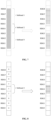
- sub-band full-duplex uses existence of sub-bands to divide uplink and downlink transmissions in a frequency domain.
- U represents an uplink sub-band (i.e., a frequency domain resource for uplink transmission at that moment)
- D represents a downlink sub-band (that is, a frequency domain resource for downlink transmission at that moment). While ensuring that uplink and downlink transmissions can be performed at the same time, sub-band full-duplex further reduces interference by using frequency division, reduces complexity of base stations, and is easier to implement.
- BWP Band Width Part
- the existing standard supports discontinuous frequency domain resource allocation for a terminal device, that is, indicating whether each Resource block groups (RBG) is allocated to the terminal device through a bitmap in granularity of RBG.
- RBG Resource block groups
- the existing standard also supports continuous frequency domain resource allocation, that is, allocating a continuous section of frequency domain resources to the terminal device through a Resource Indication Value (RIV).
- RBG Resource block groups
- the terminal device is configured with multiple discontinuous frequency domain resource blocks, and boundaries of the frequency domain resource blocks are not aligned with boundaries of the RBGs, resources across sub-band boundaries, i.e., the RBG that is partly located in a downlink sub-band and partly located in an uplink sub-band, cannot be allocated to the terminal device, resulting in resource waste.
- the RBG contains more resource block resources, and accordingly the waste of resources is greater.
- Embodiments of the present disclosure provide a data transmission method and apparatus, which may accurately determine resources used for data transmission, thereby avoiding resource waste.
- a data transmission method including: receiving first configuration information, wherein the first configuration information is used to configure candidate frequency domain resources; and transmitting data on a first frequency domain resource based on the first configuration information and first sub-band information; wherein the first sub-band information indicates one or more sub-bands; based on that the first frequency domain resource is an uplink frequency domain resource, the first sub-band information is available sub-band information, and the candidate frequency domain resources include all available uplink frequency domain resources; and based on that the first frequency domain resource is a downlink frequency domain resource, the first sub-band information is unavailable sub-band information or available sub-band information, and the candidate frequency domain resources include all available downlink frequency domain resources.
- the candidate frequency domain resources are continuous frequency domain resources, and the first configuration information is an RIV; or the candidate frequency domain resources include a plurality of frequency domain resource allocation units, and the first configuration information is a bitmap including a plurality of bits each of which corresponds to one of the plurality of frequency domain resource allocation units.
- the data transmission method further includes: receiving second configuration information, wherein the second configuration information is used to configure the first sub-band information.
- the first configuration information is carried in Downlink Control Information (DCI)
- the second configuration information is carried in Radio Resource Control (RRC) signaling.
- DCI Downlink Control Information
- RRC Radio Resource Control
- the first frequency domain resource is the downlink frequency domain resource
- the first sub-band information is the unavailable sub-band information
- the first sub-band information is carried in a rate matching related information element in RRC signaling.
- a field occupied by the first sub-band information is a field newly added in the rate matching related information element.
- the first frequency domain resource is the uplink frequency domain resource
- the first frequency domain resource is an overlapped part of the candidate frequency domain resources and the one or more sub-bands indicated by the first sub-band information.
- the first frequency domain resource is the downlink frequency domain resource
- the first frequency domain resource in response to the first sub-band information being the unavailable sub-band information, is a portion of the candidate frequency domain resources other than the one or more sub-bands indicated by the first sub-band information; or in response to the first sub-band information being the available sub-band information, is a portion of the candidate frequency domain resources that overlaps with the one or more sub-bands indicated by the first sub-band information.
- the method further includes: punching the candidate frequency domain resources using the one or more sub-bands indicated by the first sub-band information to acquire the first frequency domain resource.
- a data transmission method including: transmitting first configuration information, wherein the first configuration information is used to configure candidate frequency domain resources; and transmitting data on a first frequency domain resource based on the first configuration information and first sub-band information; wherein the first sub-band information indicates one or more sub-bands; based on that the first frequency domain resource is an uplink frequency domain resource, the first sub-band information is available sub-band information, and the candidate frequency domain resources include all available uplink frequency domain resources; and based on that the first frequency domain resource is a downlink frequency domain resource, the first sub-band information is unavailable sub-band information or available sub-band information, and the candidate frequency domain resources include all available downlink frequency domain resources.
- the candidate frequency domain resources are continuous frequency domain resources, and the first configuration information is an RIV; or the candidate frequency domain resources include a plurality of frequency domain resource allocation units, and the first configuration information is a bitmap including a plurality of bits each of which corresponds to one of the plurality of frequency domain resource allocation units.
- the data transmission method further includes: transmitting second configuration information, wherein the second configuration information is used to configure the first sub-band information.
- the first configuration information is carried in DCI
- the second configuration information is carried in RRC signaling.
- the first frequency domain resource is the downlink frequency domain resource
- the first sub-band information is the unavailable sub-band information
- the first sub-band information is carried in a rate matching related information element in RRC signaling.
- a field occupied by the first sub-band information is a field newly added in the rate matching related information element.
- the first frequency domain resource is the uplink frequency domain resource
- the first frequency domain resource is an overlapped part of the candidate frequency domain resources and the one or more sub-bands indicated by the first sub-band information.
- the first frequency domain resource is the downlink frequency domain resource
- the first frequency domain resource in response to the first sub-band information being the unavailable sub-band information, is a portion of the candidate frequency domain resources other than the one or more sub-bands indicated by the first sub-band information; or in response to the first sub-band information being the available sub-band information, is a portion of the candidate frequency domain resources that overlaps with the one or more sub-bands indicated by the first sub-band information.
- the method further includes: punching the candidate frequency domain resources using the one or more sub-bands indicated by the first sub-band information to acquire the first frequency domain resource.
- a data transmission apparatus including a processing circuitry, and a transmitting and receiving circuitry; wherein the processing circuitry is configured to receive first configuration information via the transmitting and receiving circuitry, wherein the first configuration information is used to configure candidate frequency domain resources; and the processing circuitry is further configured to transmit data on a first frequency domain resource via the transmitting and receiving circuitry based on the first configuration information and first sub-band information; wherein the first sub-band information indicates one or more sub-bands; based on that the first frequency domain resource is an uplink frequency domain resource, the first sub-band information is available sub-band information, and the candidate frequency domain resources include all available uplink frequency domain resources; and based on that the first frequency domain resource is a downlink frequency domain resource, the first sub-band information is unavailable sub-band information or available sub-band information, and the candidate frequency domain resources include all available downlink frequency domain resources.
- the candidate frequency domain resources are continuous frequency domain resources, and the first configuration information is an RIV; or the candidate frequency domain resources include a plurality of frequency domain resource allocation units, and the first configuration information is a bitmap including a plurality of bits each of which corresponds to one of the plurality of frequency domain resource allocation units.
- the processing circuitry is further configured to: receive second configuration information via the transmitting and receiving circuitry, wherein the second configuration information is used to configure the first sub-band information.
- the first configuration information is carried in DCI
- the second configuration information is carried in RRC signaling.
- the first frequency domain resource is the downlink frequency domain resource
- the first sub-band information is the unavailable sub-band information
- the first sub-band information is carried in a rate matching related information element in RRC signaling.
- a field occupied by the first sub-band information is a field newly added in the rate matching related information element.
- the first frequency domain resource is the uplink frequency domain resource
- the first frequency domain resource is an overlapped part of the candidate frequency domain resources and the one or more sub-bands indicated by the first sub-band information.
- the first frequency domain resource is the downlink frequency domain resource
- the first frequency domain resource in response to the first sub-band information being the unavailable sub-band information, is a portion of the candidate frequency domain resources other than the one or more sub-bands indicated by the first sub-band information; or in response to the first sub-band information being the available sub-band information, is a portion of the candidate frequency domain resources that overlaps with the one or more sub-bands indicated by the first sub-band information.
- the method further includes: punching the candidate frequency domain resources using the one or more sub-bands indicated by the first sub-band information to acquire the first frequency domain resource.
- a data transmission apparatus including a processing circuitry, and a transmitting and receiving circuitry; wherein the processing circuitry is configured to transmit first configuration information via the transmitting and receiving circuitry, wherein the first configuration information is used to configure candidate frequency domain resources; and the processing circuitry is further configured to transmit data on a first frequency domain resource via the transmitting and receiving circuitry based on the first configuration information and first sub-band information; wherein the first sub-band information indicates one or more sub-bands; based on that the first frequency domain resource is an uplink frequency domain resource, the first sub-band information is available sub-band information, and the candidate frequency domain resources include all available uplink frequency domain resources; and based on that the first frequency domain resource is a downlink frequency domain resource, the first sub-band information is unavailable sub-band information or available sub-band information, and the candidate frequency domain resources include all available downlink frequency domain resources.
- the candidate frequency domain resources are continuous frequency domain resources, and the first configuration information is an RIV; or the candidate frequency domain resources include a plurality of frequency domain resource allocation units, and the first configuration information is a bitmap including a plurality of bits each of which corresponds to one of the plurality of frequency domain resource allocation units.
- the processing circuitry is further configured to: transmit second configuration information via the transmitting and receiving circuitry, wherein the second configuration information is used to configure the first sub-band information.
- the first configuration information is carried in DCI
- the second configuration information is carried in RRC signaling.
- the first frequency domain resource is the downlink frequency domain resource
- the first sub-band information is the unavailable sub-band information
- the first sub-band information is carried in a rate matching related information element in RRC signaling.
- a field occupied by the first sub-band information is a field newly added in the rate matching related information element.
- the first frequency domain resource is the uplink frequency domain resource
- the first frequency domain resource is an overlapped part of the candidate frequency domain resources and the one or more sub-bands indicated by the first sub-band information.
- the first frequency domain resource is the downlink frequency domain resource
- the first frequency domain resource in response to the first sub-band information being the unavailable sub-band information, is a portion of the candidate frequency domain resources other than the one or more sub-bands indicated by the first sub-band information; or in response to the first sub-band information being the available sub-band information, is a portion of the candidate frequency domain resources that overlaps with the one or more sub-bands indicated by the first sub-band information.
- the method further includes: punching the candidate frequency domain resources using the one or more sub-bands indicated by the first sub-band information to acquire the first frequency domain resource.
- a computer readable storage medium having computer instructions stored therein is provided, where when the computer instructions are executed by a processor, any one of the above methods provided in the first aspect or the second aspect is performed.
- a terminal device which includes a memory and a processor is provided, where the memory has computer instructions stored therein, and when the processor executes the computer instructions, any one of the above methods provided in the first aspect or the second aspect is performed.
- a network device which includes a memory and a processor is provided, where the memory has computer instructions stored therein, and when the processor executes the computer instructions, any one of the above methods provided in the first aspect or the second aspect is performed.
- a computer program product having computer instructions stored therein is provided, where when the computer instructions are executed by a processor, any one of the above methods provided in the first aspect or the second aspect is performed.
- a communication system which includes the above terminal device and the above network device is provided.
- Embodiments of the present disclosure may provide following advantages.
- the network device transmits the first configuration information
- the terminal device receives the first configuration information
- the first configuration information is used to configure the candidate frequency domain resources
- the candidate frequency domain resources include all available uplink frequency domain resources or all available downlink frequency domain resources.
- the terminal device or the network device can learn the candidate frequency domain resources, and further determine the first frequency domain resource based on the first configuration information and the first sub-band information.
- Embodiments of the present disclosure may accurately determine a position of the first frequency domain resource, thereby avoiding resource waste.
- the first frequency domain resource is the uplink frequency domain resource
- the first frequency domain resource is an overlapped part of the candidate frequency domain resources and the one or more sub-bands indicated by the first sub-band information.
- the candidate frequency domain resources include all the available uplink frequency domain resources which may include some unavailable resources, such as downlink resources or uplink resources allocated to other terminal devices, all effective uplink frequency domain resources, i.e., the first frequency domain resource, can be acquired by overlapping the candidate frequency domain resources with the available sub-bands, thereby avoiding resource waste.
- the first frequency domain resource is the downlink frequency domain resource
- the first frequency domain resource in response to the first sub-band information being the unavailable sub-band information, is a portion of the candidate frequency domain resources other than the one or more sub-bands indicated by the first sub-band information, and the candidate frequency domain resources are punched using the one or more sub-bands indicated by the first sub-band information to acquire the first frequency domain resource.
- the candidate frequency domain resources include all available downlink frequency domain resources which may include some unavailable resources, such as uplink resources or downlink resources allocated to other terminal devices, all effective uplink frequency domain resources, i.e., the first frequency domain resource, can be acquired by punching the unavailable resources in combination with the unavailable sub-band information, thereby avoiding resource waste.
- Communication systems applicable to embodiments of the present disclosure include but are not limited to Long Term Evolution (LTE) systems, 5th-generation (5G) systems, New Radio (NR) systems, and future evolution systems or a fusion system of various communications.
- the 5G system may be a non-standalone (NSA) 5G system or a standalone (SA) 5G system.
- SA standalone
- the technical solutions of the present disclosure also may be applied to different network architectures, including but not limited to a relay network architecture, a dual-link architecture, and a vehicle-to-everything architecture.
- the present disclosure mainly relates to communication between a terminal device and a network device.
- the network device in the embodiments of the present disclosure may also be referred to as an access network device, such as a base station (also called a base station equipment), and is a device deployed in a Radio Access Network (RAN) to provide radio communication functions.
- a base station also called a base station equipment
- RAN Radio Access Network
- an equipment that provides a base station function in a 2G network includes a Base Transceiver Station (BTS) and a Base Station Controller (BSC).
- BTS Base Transceiver Station
- BSC Base Station Controller
- An equipment that provides the base station function in a 3G network includes a Node B.
- An equipment that provides the base station function in a 4G network includes an evolved Node B (eNB).
- eNB evolved Node B
- an equipment that provides the base station function is an Access Point (AP).
- WLAN Wireless Local Area Network
- AP Access Point
- An equipment that provides the base station function in a 5G New Radio (NR) includes gNB and a continuously evolved Node B (ng-eNB), where gNB and the terminal use NR technology for communication, ng-eNB and the terminal use Evolved Universal Terrestrial Radio Access (E-UTRA) technology for communication, and both gNB and ng-eNB can be connected to a 5G core network.
- ng-eNB continuously evolved Node B
- E-UTRA Evolved Universal Terrestrial Radio Access
- both gNB and ng-eNB can be connected to a 5G core network.
- the base station also refers to an equipment that provides the base station function in a new communication system in the future.
- the terminal device in the embodiments of the present disclosure may refer to various forms of access terminal, user unit, user station, Mobile Station (MS), remote station, remote terminal, mobile equipment, user terminal, wireless communication equipment, user agent or user device.
- the terminal device may further be a cellular phone, a cordless phone, a Session Initiation Protocol (SIP) phone, a Wireless Local Loop (WLL) station, a Personal Digital Assistant (PDA), a handheld device with a wireless communication function, a computing device or other processing devices connected to a wireless modems, an in-vehicle device, a wearable device, a terminal equipment in the future 5G network, or a terminal equipment in a future evolved Public Land Mobile Network (PLMN), which is not limited in the embodiments of the present disclosure.
- the terminal device may also be referred to as a UE or a terminal.
- sub-band full-duplex may divide the BWP into multiple sub-bands.
- a sub-band is an uplink sub-band in one time period (for example, one or more subframes, one or more slots, one or more mini slots, one or more Orthogonal Frequency Division Multiplexing (OFDM) symbols, etc.), and may be a downlink sub-band in another time period, and vice versa. This can be understood specifically from FIG. 1 . In other words, sub-bands are not actually classified into uplink and downlink sub-bands.
- OFDM Orthogonal Frequency Division Multiplexing
- a sub-band When a sub-band is used for uplink transmission, it can be called an uplink sub-band, and when a sub-band is used for downlink reception, it can be called a downlink sub-band.
- an uplink sub-band When a sub-band is used for uplink transmission, it can be called an uplink sub-band, and when a sub-band is used for downlink reception, it can be called a downlink sub-band.
- specific resources used by a terminal device for data transmission need to be further indicated through DCI.
- Type0 supports continuous or non-continuous resource allocation, where different RBG sizes are selected according to bandwidth of different BWPs, each RBG includes multiple Resource Blocks (RBs), and then RBG is used as the granularity to indicate which RBGs are allocated to the terminal device in the form of bitmap in the DCI.
- Type1 only supports continuous frequency domain resource allocation, where a starting position and length of the allocated frequency domain resources are notified to the terminal device through joint coding in the form of RIV in the DCI.
- the sub-band used for uplink transmission belongs to non-continuous frequency domain resources which can only be allocated to the terminal device in the form of type0.
- the terminal device when the terminal device is configured with multiple discontinuous frequency domain resource blocks, and boundaries of the frequency domain resource blocks are not aligned with boundaries of the RBGs, resources across sub-band boundaries, i.e., the RBG that is partly located in a downlink sub-band and partly located in an uplink sub-band, cannot be allocated to the terminal device, resulting in resource waste.
- the sub-band full-duplex divides an entire BWP into three sub-bands.
- An uplink sub-band (shown as an oblique shaded part in FIG. 2 ) is in the middle of the BWP, and two downlink sub-bands (shown as a vertical shaded part in FIG. 2 ) are at both ends of the entire BWP, and boundaries of the uplink and downlink sub-bands are not aligned with an RBG.
- a network device wants to allocate two frequency domain resource blocks for downlink transmission to a same terminal device, the network device can only use the type0 frequency domain resource allocation manner to set the 9-bit bitmap to 111000111 in the DCI to allocate RBG0-RBG2 and RBG6-RBG8 to the terminal device.
- downlink frequency domain resources in RBG3 and RBG5 cannot be allocated to the terminal device, resulting in a waste of frequency domain resources.
- FIG. 3 is a flow chart of a data transmission method according to an embodiment. Referring to FIG. 3 , the method includes 301, 302 and 303.
- a network device transmits receiving first configuration information, where the first configuration information is used to configure candidate frequency domain resources. Accordingly, a terminal device receives the first configuration information.
- Actions performed by the network device may be performed by the network device or by a chip or chip module in the network device.
- Actions performed by the terminal device may be performed by the terminal device or by a chip or chip module in the terminal device.
- the first configuration information may be carried in DCI.
- the candidate frequency domain resources may be used to determine downlink transmission resources or uplink transmission resources.
- the candidate frequency domain resources may have following two situations.
- the candidate frequency domain resources include multiple frequency domain resource allocation units.
- the first configuration information is a bitmap including a plurality of bits each of which corresponds to one frequency domain resource allocation unit.
- the frequency domain resource allocation unit may be an RBG.
- the candidate frequency domain resources in the embodiment are non-continuous resources, and may be indicated in a type0 manner.
- the DCI indicates which RBGs are allocated to the terminal device in a bitmap manner.
- the candidate frequency domain resources include RBG0 to RBG3 and RBG5 to RBG8.
- the first configuration information of the 9-bit bitmap is set to 111101111 in DCI1_1. That is, when an RBG includes both downlink available resources and unavailable resources, a corresponding bit of the RBG in the bitmap is 1, that is, the RBG is also indicated to the terminal device through DCI.
- the candidate frequency domain resources are continuous frequency domain resources.
- the frequency domain resource allocation unit may be an RB.
- the first configuration information is an RIV which is acquired by jointly encoding a starting RB position and RB length of the continuous frequency domain resource. It should be noted that a specific method of joint encoding using the starting RB position and RB length of the frequency domain resources to acquire the RIV may be referred to the existing standards, which is not limited in the embodiments of the present disclosure.
- the candidate frequency domain resources in the embodiment are continuous resources, which may be indicated in the type1 manner.
- Type1 supports continuous frequency domain resource allocation, and notifies the terminal device of the starting RB position and RB length of the allocated frequency domain resources in the RIV through joint coding.
- the candidate frequency domain resources include a continuous section of frequency domain resource, with RB start as the starting RB position and L RBs as the RB length, that is, L RBs represents a number of RBs.
- the candidate frequency domain resources include the downlink available resources allocated to the terminal device and an unavailable resource sub-band, that is, the candidate frequency domain resources include an uplink sub-band shown in an oblique shaded portion in addition to a downlink sub-band shown in a vertical line portion in FIG. 5 .
- the terminal device transmits data on a first frequency domain resource based on the first configuration information and first sub-band information.
- the first sub-band information indicates one or more sub-bands. Based on that the first frequency domain resource is an uplink frequency domain resource, the first sub-band information is available sub-band information, and the candidate frequency domain resources include all available uplink frequency domain resources. Based on that the first frequency domain resource is a downlink frequency domain resource, the first sub-band information is unavailable sub-band information or available sub-band information, and the candidate frequency domain resources include all available downlink frequency domain resources.
- the candidate frequency domain resources when the first frequency domain resource is the uplink frequency domain resource, the candidate frequency domain resources include frequency domain resource allocation units where the uplink frequency domain resource is located; and when the first frequency domain resource is the downlink frequency domain resource, the candidate frequency domain resources include frequency domain resource allocation units where the downlink frequency domain resource is located.
- the network device transmits data on the first frequency domain resource based on the first configuration information and the first sub-band information.
- the terminal device transmits the data on the first frequency domain resource, and the network device receives the data on the first frequency domain resource. If the data is downlink data, the network device transmits the data on the first frequency domain resource, and the terminal device receives the data on the first frequency domain resource.
- the first sub-band information is used to indicate a frequency domain position of one or more sub-bands, and the frequency domain position may be represented by RB, for example, the position of the sub-band is determined by an index of RB.
- the first sub-band information is unavailable sub-band information or available sub-band information
- the available sub-band may be a downlink sub-band
- the unavailable sub-band may be an uplink sub-band or a resource allocated to other terminal devices.
- the first sub-band information is available sub-band information
- the available sub-band may be an uplink sub-band.
- the network device may transmit second configuration information to the terminal device. Accordingly, the terminal device receives the second configuration information.
- the second configuration information is used to configure the first sub-band information.
- the first sub-band information may be used to determine a position of the first sub-band.
- the first sub-band information may be, for example, an identity of the sub-band or information of RBs included in the sub-band (for example, an RB index, and for example, a starting RB index and an RB length).
- the first sub-band information may also include a type of the sub-band (such as an available sub-band or an unavailable sub-band), etc.
- the second configuration information includes identity 0 of sub-band 0, identity 1 of sub-band 1, and identity 2 of sub-band 2.
- the type of sub-band 0 is an available sub-band
- the type of sub-band 1 is an available sub-band
- the type of sub-band 2 is an unavailable sub-band.
- the second configuration information may be carried in RRC signaling.
- the terminal device or the network device may determine the first frequency domain resource based on the first configuration information and the first sub-band information, and transmit data on the first frequency domain resource.
- the process of determining the first frequency domain resource is different.
- the process of determining the first frequency domain resource in a first situation (the first frequency domain resource is a downlink frequency domain resource) and a second situation (the first frequency domain resource is an uplink frequency domain resource) is exemplarily described below.
- the first frequency domain resource is a downlink frequency domain resource.
- the first frequency domain resource may be determined by a following manner 1 or manner 2.
- the first frequency domain resource is an overlapped portion of the candidate frequency domain resources and the one or more sub-bands indicated by the first sub-band information.
- 'resourceAllocation' in 'PDSCH-Config' in RRC signaling is configured as resourceAllocationType0, that is, type0 frequency domain resource allocation.
- resourceAllocationType0 that is, type0 frequency domain resource allocation.
- the candidate frequency domain resources assigned to the terminal device are RBG0 to RBG3 and RBG5 to RBG8.
- the allocated resources are effective merely in downlink sub-bands.
- sub-band 0 and sub-band 1 an overlapped part of the candidate frequency domain resources, sub-band 0 and sub-band 1 is used as final effective resources (the first frequency domain resource) in the downlink sub-bands, as shown in a vertical line shaded part in FIG. 6 .
- 'resourceAllocation' in 'PDSCH-Config' in the RRC signaling is configured as resourceAllocationType1, that is, type1 frequency domain resource allocation.
- resourceAllocationType1 that is, type1 frequency domain resource allocation.
- the frequency domain resource assignment field in DCI1_0 or DCI1_1 is set to a jointly coding value RIV, it is determined that the frequency domain resources allocated to the terminal device are shown in a diamond shaded part on the left side in FIG. 7 , that is, the candidate frequency domain resources are frequency domain resources starting from RB start and having a length of L RBs RBs.
- the allocated resources are effective merely in the available sub-bands.
- resource positions of the available sub-bands configured by RRC are sub-band 0 and sub-band 1
- final effective resources (the first frequency domain resources) in the downlink sub-bands are acquired, as shown in a vertical line shaded part in FIG. 7 .
- the first sub-band information is unavailable sub-band information
- the first frequency domain resource is a portion of the candidate frequency domain resources other than the one or more sub-bands indicated by the first sub-band information.
- the first sub-band information is carried in a rate matching related information element in RRC signaling.
- a field occupied by the first sub-band information may be a newly added field in the rate matching related information element.
- a field 'Sub-band' may be added to a parameter 'patternType' in an RRC related information element IE RateMatchPattern to indicate a sub-band identity of punching, i.e., the first sub-band information.
- a specific position of each sub-band may be indicated by other signaling or other information elements in the RRC signaling. Therefore, the specific position of the frequency domain resources that need to be punched may be determined based on the first sub-band information and the specific positions of the sub-bands indicated by other information elements.
- the method further includes: the terminal device and the network device using the one or more sub-bands indicated by the first sub-band information to punch the candidate frequency domain resources to acquire the first frequency domain resource.
- a field 'Sub-band' is added to ⁇ patternType' in IE RateMatchPattern in RRC signaling to indicate punching sub-band information (i.e., the first sub-band information).
- the candidate frequency domain resources are acquired by the type1 resource allocation method, as shown in the diamond shaded portion on the left side in FIG. 7 .
- PDSCH Configuration Information element i.e., PDSCH Config
- the unavailable sub-band frequency domain resources in the candidate frequency domain resources are punched to acquire final effective resources (the first frequency domain resources) in the downlink sub-bands, as shown in the vertical line shaded portion in FIG. 7 .
- indication information may be added to DCI, where the indication information is used to indicate that the candidate frequency domain resources are punched using the one or more sub-bands indicated by the first sub-band information, or to indicate whether the candidate frequency domain resources are punched using the one or more sub-bands indicated by the first sub-band information.
- the indication information may be carried in a dummy parameter, for example, when the dummy parameter is set to semi-static, it indicates that the candidate frequency domain resources are punched using the one or more sub-bands indicated by the first sub-band information, and when the dummy parameter is set to dynamic, it indicates that the DCI needs to dynamically indicate whether the candidate frequency domain resources are punched using the one or more sub-bands indicated by the first sub-band information.
- the candidate frequency domain resources are acquired through type0 or type1 resource allocation, as shown in the diamond shaded portion on the left side in FIG. 7 .
- 'Sub-band' in 'RateMatchPattern' in ⁇ rateMatchPatternToAddModList' in PDSCH-Config is set to Sub-bandID of the unavailable sub-band (that is, sub-band 2), and the dummy parameter is set to semi-static, the unavailable sub-band frequency domain resources of the candidate frequency domain resources are directly punched to acquire final effective resources (the first frequency domain resource) in the downlink sub-bands, as shown in the vertical line shaded portion in FIG. 7 .
- the candidate frequency domain resources are acquired through type0 or type1 resource allocation.
- 'Sub-band' in ⁇ RateMatchPattern' in ⁇ rateMatchPatternToAddModList' in 'PDSCH-Config' is set to the Sub-bandID of the uplink sub-band (i.e., sub-band 2), the dummy parameter is set to dynamic, and 'RateMatchPatternID' which is configured with a sub-band is added to 'rateMatchPatternGroup1' or ⁇ rateMatchPatternGroup2' in ⁇ PDSCH-Config'. In this way, it is possible to dynamically indicate whether to punch the sub-band through a matching indicator field in DCI1_1.
- the rate matching indicator field in DCI1_1 is set to 1, it means that the uplink sub-band is punched, and the final effective resources (the first frequency domain resource) in the downlink sub-bands can be acquired, as shown in the vertical line shaded part in FIG. 7 . If the rate matching indicator field in DCI1_1 is set to 0, it means that the uplink sub-band is not punched.
- ⁇ rateMatchPattern' not included in ⁇ rateMatchPatternGroup 1' and ⁇ rateMatchPatternGroup2' belongs to a static rate matching mode, that is, it contains Resource Elements (REs) that are not available for PDSCH, corresponding to semi-static rate matching.
- ⁇ rateMatchPattern' included in ⁇ rateMatchPatternGroup 1' and ⁇ rateMatchPatternGroup2' belongs to a dynamically configured rate matching mode, where whether REs can be used for PDSCH is dynamically indicated by DCI, corresponding to dynamic rate matching.
- the first frequency domain resource is an uplink frequency domain resource.
- the first frequency domain resource is an overlapped portion of the candidate frequency domain resources and the one or more sub-bands indicated by the first sub-band information.
- the first frequency domain resource can be determined only through the overlapped part of the candidate frequency domain resources and the uplink sub-bands, but cannot be determined by rate matching.
- 'resourceAllocation' in 'PDSCH-Config' in RRC signaling is configured as resourceAllocationType0, i.e., type0 frequency domain resource allocation.
- resourceAllocationType0 i.e., type0 frequency domain resource allocation.
- the candidate frequency domain resources allocated to the terminal device are RBG3 to RBG5.
- the allocated resources are effective merely in the uplink sub-bands.
- the embodiments of the present disclosure provide a frequency domain resource allocation method suitable for sub-band full-duplex.
- the sub-band information in the BWP in the frequency domain resource configuration or rate matching, all frequency domain resources in the sub-bands can be configured to reduce resource waste.
- the downlink frequency domain resources in RBG3 and RBG5 cannot be allocated to the terminal device.
- the downlink frequency domain resources in RBG3 and RBG5 can be allocated to the terminal device, thereby avoiding resource waste.
- the data transmission method may be implemented in a form of software program which runs in a processor integrated within a chip or chip module.
- the method may be implemented using a combination of software and hardware, which is not limited in the present disclosure.
- FIG. 9 is a block diagram of a data transmission apparatus 90 according to an embodiment.
- the data transmission apparatus 90 includes: a processing circuitry 901 and a transmitting and receiving circuitry 902.
- the processing circuitry 901 is configured to receive first configuration information via the transmitting and receiving circuitry 902, wherein the first configuration information is used to configure candidate frequency domain resources.
- the processing circuitry 901 is further configured to transmit data on a first frequency domain resource via the transmitting and receiving circuitry 902 based on the first configuration information and first sub-band information; wherein the first sub-band information indicates one or more sub-bands; based on that the first frequency domain resource is an uplink frequency domain resource, the first sub-band information is available sub-band information, and the candidate frequency domain resources include all available uplink frequency domain resources; and based on that the first frequency domain resource is a downlink frequency domain resource, the first sub-band information is unavailable sub-band information or available sub-band information, and the candidate frequency domain resources include all available downlink frequency domain resources.
- the data transmission apparatus 90 may correspond to a chip with a data transmission function in a terminal device, such as a System-On-Chip (SOC) or a baseband chip, or to a chip module including a chip with a data transmission function in the terminal device, or to a chip module including a chip with a data processing function, or to the terminal device.
- a terminal device such as a System-On-Chip (SOC) or a baseband chip
- SOC System-On-Chip
- a baseband chip or to a chip module including a chip with a data transmission function in the terminal device, or to a chip module including a chip with a data processing function, or to the terminal device.
- FIG. 10 is a block diagram of a data transmission apparatus 100 according to an embodiment.
- the data transmission apparatus 100 includes: a processing circuitry 1001 and a transmitting and receiving circuitry 1002.
- the processing circuitry 1001 is configured to transmit first configuration information via the transmitting and receiving circuitry 1002, wherein the first configuration information is used to configure candidate frequency domain resources.
- the processing circuitry 1001 is further configured to transmit data on a first frequency domain resource via the transmitting and receiving circuitry 1002 based on the first configuration information and first sub-band information; wherein the first sub-band information indicates one or more sub-bands; based on that the first frequency domain resource is an uplink frequency domain resource, the first sub-band information is available sub-band information, and the candidate frequency domain resources include all available uplink frequency domain resources; and based on that the first frequency domain resource is a downlink frequency domain resource, the first sub-band information is unavailable sub-band information or available sub-band information, and the candidate frequency domain resources include all available downlink frequency domain resources.
- the data transmission apparatus 100 may correspond to a chip with a data transmission function in a network device, such as an SOC or a baseband chip, or to a chip module including a chip with a data transmission function in the network device, or to a chip module including a chip with a data processing function, or to the network device.
- a network device such as an SOC or a baseband chip
- a chip module including a chip with a data transmission function in the network device or to a chip module including a chip with a data processing function, or to the network device.
- Each module/unit of each apparatus and product described in the above embodiments may be a software module/unit or a hardware module/unit, or may be a software module/unit in part, and a hardware module/unit in part.
- each module/unit included therein may be implemented by hardware such as circuits; or, at least some modules/units may be implemented by a software program running on a processor integrated inside the chip, and the remaining (if any) part of the modules/units may be implemented by hardware such as circuits.
- each module/unit included therein may be implemented by hardware such as circuits.
- Different modules/units may be disposed in a same component (such as a chip or a circuit module) or in different components of the chip module. Or at least some modules/units may be implemented by a software program running on a processor integrated inside the chip module, and the remaining (if any) part of the modules/units may be implemented by hardware such as circuits. For each apparatus or product applied to or integrated in a terminal, each module/unit included therein may be implemented by hardware such as circuits. Different modules/units may be disposed in a same component (such as a chip or a circuit module) or in different components of the terminal. Or at least some modules/units may be implemented by a software program running on a processor integrated inside the terminal, and the remaining (if any) part of the modules/units may be implemented by hardware such as circuits.
- a computer readable storage medium having computer instructions stored therein is provided, where when the computer instructions are executed, any of the above data transmission methods is performed.
- the storage medium may include a ROM, a RAM, a magnetic disk or an optical disk.
- the storage medium may include a non-volatile or a non-transitory memory.
- FIG. 11 is a diagram of hardware structures of a communication apparatus according to an embodiment.
- the apparatus includes a processor 1101, a memory 1102 and a transceiver 1103.
- the processor 1101 may be a general Central Processing Unit (CPU), a microprocessor, an Application-Specific Integrated Circuit (ASIC), or one or more integrated circuits used to control execution of a program of the present application.
- the processor 1101 may include multiple CPUs, and may be a single-CPU processor or a multi-CPU processor.
- the processor here may refer to one or more devices, circuits or processing cores for processing data (e.g., computer program instructions).
- the memory 1102 may be ROM or other types of static storage devices that can store static information and instructions, RAM or other types of dynamic storage devices that can store information and instructions, Electrically Erasable Programmable Read-Only Memory (EEPROM), Compact Disc-Read Only Memory (CD-ROM) or other optical disc storage, optical disk storage (including compressed optical discs, laser discs, optical discs, digital versatile discs, Blu-ray discs, etc.), magnetic disk storage media or other magnetic storage devices, or any other medium that can be used to carry or store desired program codes in the form of instructions or data structures and can be accessed by a computer, which is not limited in the embodiments of the present disclosure.
- EEPROM Electrically Erasable Programmable Read-Only Memory
- CD-ROM Compact Disc-Read Only Memory
- optical disk storage including compressed optical discs, laser discs, optical discs, digital versatile discs, Blu-ray discs, etc.
- magnetic disk storage media or other magnetic storage devices or any other medium that can be used to carry or store desired program codes in the form of instructions
- the memory 1102 may exist independently (in this case, the memory 1102 may be located outside the device or within the device), or may be integrated with the processor 1101.
- the memory 1102 may include computer program codes.
- the processor 1101 is used to execute the computer program codes stored in the memory 1102, thereby implementing the method provided in the embodiments of the present disclosure.
- the processor 1101, the memory 1102 and the transceiver 1103 are coupled through a bus.
- the transceiver 1103 is used to communicate with other devices or communication networks.
- the transceiver 1103 may include a transmitter and a receiver.
- a device used to implement a receiving function in the transceiver 1103 can be regarded as a receiver which is used to perform receiving steps in the embodiments of the present disclosure.
- a device used to implement a transmitting function in the transceiver 1103 can be regarded as a transmitter which is used to perform transmitting steps in the embodiments of the present disclosure.
- the processor 1101 is configured to control and manage actions of the terminal device.
- the processor 1101 is configured to support the terminal device to perform 301 and 302 in FIG. 3 , or 301, 401, 302 and 402 in FIG. 4 , and/or actions performed by the terminal device in other procedures described in the embodiments of the present disclosure.
- the processor 1101 may communicate with other network entities through the transceiver 1103, for example, with the network device described above.
- the memory 1102 is configured to store program codes and data of the terminal device. When the processor runs the computer program, the transceiver 1103 is controlled to receive one or more of RRC signaling and DCI.
- the processor 1101 is configured to control and manage actions of the network device.
- the processor 1101 is configured to support the network device to perform 301 and 303 in FIG. 3 , or 401, 301, 303 and 402 in FIG. 4 , and/or actions performed by the network device in other procedures described in the embodiments of the present disclosure.
- the processor 1101 may communicate with other network entities through the transceiver 1103, for example, with the terminal device described above.
- the memory 1102 is configured to store program codes and data of network devices. When the processor runs the computer program, the transceiver 1103 is controlled to transmit one or more of RRC signaling and DCI.
- a unidirectional communication link from an access network to a terminal is defined as a downlink, data transmitted on the downlink is downlink data, and a transmission direction of the downlink data is called a downlink direction.
- a unidirectional communication link from a terminal to an access network is defined as an uplink, data transmitted on the uplink is uplink data, and a transmission direction of the uplink data is called an uplink direction.
- the “plurality” in the embodiments of the present disclosure refers to two or more.
- connection in the embodiments of the present disclosure refers to various connection ways such as direct connection or indirect connection to realize communication between devices, which is not limited in the embodiments of the present disclosure.
- the above embodiments may be implemented in whole or in part by software, hardware, firmware or any combination thereof.
- the above embodiments may be implemented in whole or in part in the form of a computer program product.
- the computer program product includes one or more computer instructions or computer programs.
- the procedures or functions according to the embodiments of the present disclosure are wholly or partially generated when the computer instructions or the computer programs are loaded or executed on a computer.
- the computer may be a general-purpose computer, a special purpose computer, a computer network, or other programmable device.
- the computer instructions may be stored in a computer readable storage medium or transmitted from one computer readable storage medium to another computer readable storage medium, for example, the computer instructions may be transmitted from one website, computer, server or data center to another website, computer, server or data center by wire or in a wireless manner.
- the computer readable storage medium may be any available medium that the computer can access, or a data storage device including a collection of one or more available media, such as a server or a data center.
- sequence numbers of the above-mentioned processes do not represent an execution sequence, and the execution sequence of each process should be determined by its function and inherent logic, which does not limit an implementation process of the embodiments of the present disclosure.
- the disclosed method, device and system may be implemented in other ways.
- the above device embodiments are merely illustrative, and for example, division of units is merely one logical division, and other divisions may be realized in practice, for example, a plurality of units or components may be combined or integrated into another system, or some features may be omitted, or not executed.
- the shown or discussed mutual coupling or direct coupling or communication connection may be an indirect coupling or communication connection via some interfaces, devices or units, and may be in an electrical, mechanical or other form.
- the units described as separate parts may or may not be physically separate, and parts shown as units may or may not be physical units, that is, may be disposed in one place, or may be distributed on a plurality of network units. Some or all of the units can be selected according to practical requirements to achieve the purpose of the solutions of the embodiments.
- functional units in the embodiments of the present disclosure may be integrated in one processing unit, or each unit may be physically separate, or two or more units may be integrated in one unit.
- the integrated units can be realized in a form of hardware, or in a form of hardware plus a software functional unit.
- the integrated units implemented in the form of the software functional unit may be stored in a computer readable storage medium.
- the software functional unit is stored in a storage medium and includes several instructions for causing a computer device (a personal computer, a server or a network device) to execute some steps of the methods in the embodiments of the present disclosure.
Landscapes
- Engineering & Computer Science (AREA)
- Signal Processing (AREA)
- Computer Networks & Wireless Communication (AREA)
- Mobile Radio Communication Systems (AREA)
Applications Claiming Priority (2)
| Application Number | Priority Date | Filing Date | Title |
|---|---|---|---|
| CN202210049562.XA CN116506960A (zh) | 2022-01-17 | 2022-01-17 | 数据传输方法及装置、存储介质、终端设备、网络设备 |
| PCT/CN2023/071179 WO2023134606A1 (zh) | 2022-01-17 | 2023-01-09 | 数据传输方法及装置、存储介质、终端设备、网络设备 |
Publications (2)
| Publication Number | Publication Date |
|---|---|
| EP4468802A1 true EP4468802A1 (de) | 2024-11-27 |
| EP4468802A4 EP4468802A4 (de) | 2025-05-21 |
Family
ID=87280150
Family Applications (1)
| Application Number | Title | Priority Date | Filing Date |
|---|---|---|---|
| EP23739948.0A Pending EP4468802A4 (de) | 2022-01-17 | 2023-01-09 | Datenübertragungsverfahren und -vorrichtung sowie speichermedium, endgerät und netzwerkvorrichtung |
Country Status (4)
| Country | Link |
|---|---|
| US (1) | US20250097918A1 (de) |
| EP (1) | EP4468802A4 (de) |
| CN (1) | CN116506960A (de) |
| WO (1) | WO2023134606A1 (de) |
Cited By (1)
| Publication number | Priority date | Publication date | Assignee | Title |
|---|---|---|---|---|
| EP4572464A4 (de) * | 2022-08-12 | 2025-12-10 | Beijing Unisoc Comm Tech Co Ltd | Datenübertragungsverfahren, vorrichtung, chip, chipmodul und speichermedium |
Families Citing this family (6)
| Publication number | Priority date | Publication date | Assignee | Title |
|---|---|---|---|---|
| US20240064720A1 (en) * | 2022-08-19 | 2024-02-22 | Qualcomm Incorporated | Sub-band full duplex resource allocation |
| US20240381351A1 (en) * | 2023-05-10 | 2024-11-14 | Qualcomm Incorporated | User equipment capabilities for downlink channel estimations associated with subband full duplex operations |
| WO2025030530A1 (zh) * | 2023-08-10 | 2025-02-13 | Oppo广东移动通信有限公司 | 一种资源块组合的确定方法及装置、终端设备、网络设备 |
| CN119584309A (zh) * | 2023-08-29 | 2025-03-07 | 展讯通信(上海)有限公司 | 通信方法及装置、计算机可读存储介质 |
| WO2025059815A1 (zh) * | 2023-09-18 | 2025-03-27 | Oppo广东移动通信有限公司 | 资源指示方法、装置、设备及存储介质 |
| WO2025065450A1 (zh) * | 2023-09-27 | 2025-04-03 | 北京小米移动软件有限公司 | 资源确定方法、装置、存储介质 |
Family Cites Families (8)
| Publication number | Priority date | Publication date | Assignee | Title |
|---|---|---|---|---|
| CN103237351B (zh) * | 2012-12-05 | 2016-02-10 | 武汉邮电科学研究院 | 一种基于轮询调度的lte系统下行rb资源分配方法 |
| WO2019215706A1 (en) * | 2018-05-11 | 2019-11-14 | Telefonaktiebolaget Lm Ericsson (Publ) | Systems and methods for downlink control information (dci) size alignment |
| GB2577510B (en) * | 2018-09-26 | 2021-04-14 | Tcl Communication Ltd | Flexible NR-U wideband operation |
| CN110971322B (zh) * | 2018-09-30 | 2022-02-15 | 维沃移动通信有限公司 | 一种信息传输方法、网络设备及终端 |
| US11818072B2 (en) * | 2019-07-02 | 2023-11-14 | Comcast Cable Communications, Llc | Wireless resource determination and use |
| CN113596999A (zh) * | 2020-04-30 | 2021-11-02 | 华为技术有限公司 | 通信方法和装置 |
| US11902946B2 (en) * | 2020-05-28 | 2024-02-13 | Qualcomm Incorporated | Frequency domain allocation techniques |
| EP4169312A4 (de) * | 2020-06-22 | 2024-01-24 | QUALCOMM Incorporated | Ressourcenblocksatzzuweisung für teilband-vollduplexbetrieb |
-
2022
- 2022-01-17 CN CN202210049562.XA patent/CN116506960A/zh active Pending
-
2023
- 2023-01-09 WO PCT/CN2023/071179 patent/WO2023134606A1/zh not_active Ceased
- 2023-01-09 US US18/729,595 patent/US20250097918A1/en active Pending
- 2023-01-09 EP EP23739948.0A patent/EP4468802A4/de active Pending
Cited By (1)
| Publication number | Priority date | Publication date | Assignee | Title |
|---|---|---|---|---|
| EP4572464A4 (de) * | 2022-08-12 | 2025-12-10 | Beijing Unisoc Comm Tech Co Ltd | Datenübertragungsverfahren, vorrichtung, chip, chipmodul und speichermedium |
Also Published As
| Publication number | Publication date |
|---|---|
| US20250097918A1 (en) | 2025-03-20 |
| WO2023134606A1 (zh) | 2023-07-20 |
| EP4468802A4 (de) | 2025-05-21 |
| CN116506960A (zh) | 2023-07-28 |
Similar Documents
| Publication | Publication Date | Title |
|---|---|---|
| EP4468802A1 (de) | Datenübertragungsverfahren und -vorrichtung sowie speichermedium, endgerät und netzwerkvorrichtung | |
| US11457443B2 (en) | Method for transmitting configuration information and terminal device | |
| US12438655B2 (en) | Data communication method, terminal, and base station | |
| US10798699B2 (en) | Physical downlink control channel transmission method, base station device, and user equipment | |
| EP3634056B1 (de) | Signalübertragungsverfahren, zugehörige vorrichtung und system | |
| US12323956B2 (en) | Communication method and communications apparatus | |
| EP3595382A1 (de) | Informationsübertragungsverfahren und kommunikationsvorrichtung | |
| EP3745631B1 (de) | Drahtloskommunikationsverfahren, vorrichtung und system | |
| CN117812729A (zh) | 上行传输的方法和通信装置 | |
| US11996959B2 (en) | SRS transmission method, access network device, and terminal device | |
| EP3768015A1 (de) | Kommunikationsverfahren und -vorrichtung | |
| CN117812737A (zh) | 通信方法及通信装置 | |
| CN119111110A (zh) | 资源指示方法、装置、设备、存储介质及程序产品 | |
| CN108633058B (zh) | 一种资源分配方法及基站、ue | |
| EP4668956A1 (de) | Verfahren und vorrichtung zur bestimmung der transportblockgrösse, vorrichtung und speichermedium | |
| US20250055610A1 (en) | Method for configuring resources, terminal, and network device | |
| US20250227679A1 (en) | Communication method and apparatus | |
| CN117692092A (zh) | 通信方法及设备 | |
| WO2024059984A1 (zh) | 传输块大小的确定方法、装置、设备及存储介质 | |
| CN120642514A (zh) | 传输方法、装置、设备、存储介质及产品 | |
| CN117769036A (zh) | 通信方法及设备 | |
| CN119584310A (zh) | 通信方法及装置、计算机可读存储介质 |
Legal Events
| Date | Code | Title | Description |
|---|---|---|---|
| STAA | Information on the status of an ep patent application or granted ep patent |
Free format text: STATUS: THE INTERNATIONAL PUBLICATION HAS BEEN MADE |
|
| PUAI | Public reference made under article 153(3) epc to a published international application that has entered the european phase |
Free format text: ORIGINAL CODE: 0009012 |
|
| STAA | Information on the status of an ep patent application or granted ep patent |
Free format text: STATUS: REQUEST FOR EXAMINATION WAS MADE |
|
| 17P | Request for examination filed |
Effective date: 20240723 |
|
| AK | Designated contracting states |
Kind code of ref document: A1 Designated state(s): AL AT BE BG CH CY CZ DE DK EE ES FI FR GB GR HR HU IE IS IT LI LT LU LV MC ME MK MT NL NO PL PT RO RS SE SI SK SM TR |
|
| REG | Reference to a national code |
Ref country code: DE Ref legal event code: R079 Free format text: PREVIOUS MAIN CLASS: H04W0072040000 Ipc: H04L0005000000 |
|
| DAV | Request for validation of the european patent (deleted) | ||
| DAX | Request for extension of the european patent (deleted) | ||
| A4 | Supplementary search report drawn up and despatched |
Effective date: 20250417 |
|
| RIC1 | Information provided on ipc code assigned before grant |
Ipc: H04W 72/0453 20230101ALI20250411BHEP Ipc: H04W 72/231 20230101ALI20250411BHEP Ipc: H04W 72/232 20230101ALI20250411BHEP Ipc: H04L 5/14 20060101ALI20250411BHEP Ipc: H04L 5/00 20060101AFI20250411BHEP |