EP4468752A1 - Kommunikationsverfahren und kommunikationsvorrichtung - Google Patents
Kommunikationsverfahren und kommunikationsvorrichtung Download PDFInfo
- Publication number
- EP4468752A1 EP4468752A1 EP23752392.3A EP23752392A EP4468752A1 EP 4468752 A1 EP4468752 A1 EP 4468752A1 EP 23752392 A EP23752392 A EP 23752392A EP 4468752 A1 EP4468752 A1 EP 4468752A1
- Authority
- EP
- European Patent Office
- Prior art keywords
- terminal device
- information
- positioning
- low power
- capability
- Prior art date
- Legal status (The legal status is an assumption and is not a legal conclusion. Google has not performed a legal analysis and makes no representation as to the accuracy of the status listed.)
- Pending
Links
Images


Classifications
-
- H—ELECTRICITY
- H04—ELECTRIC COMMUNICATION TECHNIQUE
- H04W—WIRELESS COMMUNICATION NETWORKS
- H04W64/00—Locating users or terminals or network equipment for network management purposes, e.g. mobility management
-
- H—ELECTRICITY
- H04—ELECTRIC COMMUNICATION TECHNIQUE
- H04W—WIRELESS COMMUNICATION NETWORKS
- H04W4/00—Services specially adapted for wireless communication networks; Facilities therefor
- H04W4/02—Services making use of location information
-
- H—ELECTRICITY
- H04—ELECTRIC COMMUNICATION TECHNIQUE
- H04L—TRANSMISSION OF DIGITAL INFORMATION, e.g. TELEGRAPHIC COMMUNICATION
- H04L5/00—Arrangements affording multiple use of the transmission path
- H04L5/003—Arrangements for allocating sub-channels of the transmission path
- H04L5/0048—Allocation of pilot signals, i.e. of signals known to the receiver
- H04L5/0051—Allocation of pilot signals, i.e. of signals known to the receiver of dedicated pilots, i.e. pilots destined for a single user or terminal
-
- H—ELECTRICITY
- H04—ELECTRIC COMMUNICATION TECHNIQUE
- H04W—WIRELESS COMMUNICATION NETWORKS
- H04W24/00—Supervisory, monitoring or testing arrangements
- H04W24/10—Scheduling measurement reports ; Arrangements for measurement reports
-
- H—ELECTRICITY
- H04—ELECTRIC COMMUNICATION TECHNIQUE
- H04W—WIRELESS COMMUNICATION NETWORKS
- H04W52/00—Power management, e.g. Transmission Power Control [TPC] or power classes
- H04W52/02—Power saving arrangements
-
- H—ELECTRICITY
- H04—ELECTRIC COMMUNICATION TECHNIQUE
- H04W—WIRELESS COMMUNICATION NETWORKS
- H04W52/00—Power management, e.g. Transmission Power Control [TPC] or power classes
- H04W52/02—Power saving arrangements
- H04W52/0209—Power saving arrangements in terminal devices
-
- H—ELECTRICITY
- H04—ELECTRIC COMMUNICATION TECHNIQUE
- H04W—WIRELESS COMMUNICATION NETWORKS
- H04W52/00—Power management, e.g. Transmission Power Control [TPC] or power classes
- H04W52/02—Power saving arrangements
- H04W52/0209—Power saving arrangements in terminal devices
- H04W52/0261—Power saving arrangements in terminal devices managing power supply demand, e.g. depending on battery level
- H04W52/0274—Power saving arrangements in terminal devices managing power supply demand, e.g. depending on battery level by switching on or off the equipment or parts thereof
- H04W52/028—Power saving arrangements in terminal devices managing power supply demand, e.g. depending on battery level by switching on or off the equipment or parts thereof switching on or off only a part of the equipment circuit blocks
-
- H—ELECTRICITY
- H04—ELECTRIC COMMUNICATION TECHNIQUE
- H04W—WIRELESS COMMUNICATION NETWORKS
- H04W76/00—Connection management
- H04W76/20—Manipulation of established connections
-
- H—ELECTRICITY
- H04—ELECTRIC COMMUNICATION TECHNIQUE
- H04W—WIRELESS COMMUNICATION NETWORKS
- H04W76/00—Connection management
- H04W76/20—Manipulation of established connections
- H04W76/27—Transitions between radio resource control [RRC] states
-
- H—ELECTRICITY
- H04—ELECTRIC COMMUNICATION TECHNIQUE
- H04W—WIRELESS COMMUNICATION NETWORKS
- H04W76/00—Connection management
- H04W76/30—Connection release
-
- H—ELECTRICITY
- H04—ELECTRIC COMMUNICATION TECHNIQUE
- H04W—WIRELESS COMMUNICATION NETWORKS
- H04W8/00—Network data management
- H04W8/22—Processing or transfer of terminal data, e.g. status or physical capabilities
-
- H—ELECTRICITY
- H04—ELECTRIC COMMUNICATION TECHNIQUE
- H04W—WIRELESS COMMUNICATION NETWORKS
- H04W8/00—Network data management
- H04W8/22—Processing or transfer of terminal data, e.g. status or physical capabilities
- H04W8/24—Transfer of terminal data
-
- Y—GENERAL TAGGING OF NEW TECHNOLOGICAL DEVELOPMENTS; GENERAL TAGGING OF CROSS-SECTIONAL TECHNOLOGIES SPANNING OVER SEVERAL SECTIONS OF THE IPC; TECHNICAL SUBJECTS COVERED BY FORMER USPC CROSS-REFERENCE ART COLLECTIONS [XRACs] AND DIGESTS
- Y02—TECHNOLOGIES OR APPLICATIONS FOR MITIGATION OR ADAPTATION AGAINST CLIMATE CHANGE
- Y02D—CLIMATE CHANGE MITIGATION TECHNOLOGIES IN INFORMATION AND COMMUNICATION TECHNOLOGIES [ICT], I.E. INFORMATION AND COMMUNICATION TECHNOLOGIES AIMING AT THE REDUCTION OF THEIR OWN ENERGY USE
- Y02D30/00—Reducing energy consumption in communication networks
- Y02D30/70—Reducing energy consumption in communication networks in wireless communication networks
Definitions
- This application relates to the field of communication technologies, and in particular, to a communication method and a communication apparatus.
- a positioning function is an important function of 5 th generation (5 th generation, 5G) wireless communication new radio (new radio, NR).
- 5G 5 th generation
- NR new radio
- This application provides a communication method and a communication apparatus, to ensure positioning precision, so as to meet a positioning service requirement of a location management device.
- a first aspect of this application provides a communication method, including:
- a terminal device determines capability information, where the capability information includes a low power capability, and the low power capability indicates that the terminal device supports low power positioning; and the terminal device sends the capability information to a location management device.
- the terminal device has the low power capability, and the terminal device may report the low power capability to the location management device, so that the location management device determines that the terminal device supports the low power positioning.
- the low power capability indicates that the terminal device supports sending of a sounding reference signal (sounding reference signal, SRS) in low power.
- SRS sounding reference signal
- the low power capability indicates that the terminal device supports receiving of a positioning reference signal (positioning reference signal, PRS) in low power.
- PRS positioning reference signal
- the access network device may properly configure a radio resource control (radio resource control, RRC) state of the terminal device based on the capability information. Therefore, a positioning precision requirement is ensured while the low power positioning of the terminal device is implemented, to meet a positioning service requirement of the location management device.
- the low power capability is a positioning capability of the terminal device in an RRC inactive state, and the access network device may configure the terminal device to be in the RRC inactive state.
- the terminal device can participate in a positioning process in the RRC inactive state, so that precision of positioning by the location management device on the terminal device is ensured while the low power positioning of the terminal device is implemented, to ensure the positioning service requirement.
- the low power capability includes at least one of the following: a maximum quantity of SRS resources or SRS resource sets, an SRS bandwidth, and an SRS sending periodicity that are supported by the terminal device.
- a low power uplink positioning capability of the terminal device is represented by the maximum quantity of SRS resources or SRS resource sets, the SRS bandwidth, and the SRS sending periodicity that are supported by the terminal device. This helps the location management device determine the low power uplink positioning capability of the terminal device, so that the location management device determines whether the low power uplink positioning capability of the terminal device can meet the positioning service requirement of the location management device. If the requirement can be met, the location management device may indicate the access network device to perform the low power positioning on the terminal device.
- the low power capability includes at least one of the following: that the terminal device supports measurement of a PRS in an RRC inactive state, a supported positioning method, a supported PRS bandwidth, and a maximum quantity of processing resources supported in one slot.
- a low power downlink positioning capability of the terminal device is represented by information: that the terminal device supports the measurement of the PRS in the RRC inactive state, the supported positioning method, the supported PRS bandwidth, and the maximum quantity of processing resources supported in one slot. This helps the location management device determine the low power downlink positioning capability of the terminal device, so that the location management device determines whether the low power downlink positioning capability of the terminal device can meet the positioning service requirement of the location management device. If the requirement can be met, the location management device may indicate the access network device to perform the low power positioning on the terminal device.
- the method further includes:
- the terminal device receives an RRC release message from an access network device, where the RRC release message is used to release the terminal device from an RRC connected state to the RRC inactive state or an RRC idle state.
- the terminal device may receive the RRC release message sent by the access network device, so that the terminal device is released to the RRC inactive state or the RRC idle state.
- the access network device releases the terminal device to an appropriate RRC state, so that the terminal device participates in a positioning process in the RRC state, thereby implementing the low power positioning and ensuring the positioning service requirement of the location management device.
- the method further includes:
- the terminal device receives transmission reception point (transmission reception point, TRP) configuration information from the location management device, where the TRP configuration information is determined by the location management device based on the capability information.
- TRP transmission reception point
- the terminal device may receive the TRP configuration information.
- the TRP configuration information is determined by the location management device based on the capability information. This helps ensure the positioning service requirement of the location management device.
- the terminal device may receive a positioning reference signal of a specific TRP based on the TRP configuration information, and measure the positioning reference signal to obtain a measurement result. This helps the terminal device report the measurement result to the location management device, so that the location management device determines a location of the terminal device based on the measurement result, thereby positioning the terminal device.
- the method further includes:
- the terminal device receives an SRS configuration from the access network device, where the SRS configuration is determined by the access network device for the terminal device based on the capability information.
- the terminal device may receive the SRS configuration.
- the SRS configuration is determined by the access network device for the terminal device based on the capability information. This helps ensure the positioning service requirement of the location management device.
- the terminal device may send an SRS based on the SRS configuration, so that the access network device measures the SRS sent by the terminal device to obtain a measurement result.
- the access network device may report the measurement result to the location management device, so that the location management device determines a location of the terminal device based on the measurement result, thereby positioning the terminal device.
- a second aspect of this application provides a communication method, including:
- a location management device receives capability information from a terminal device, where the capability information includes a low power capability, and the low power capability indicates that the terminal device supports low power positioning; and the location management device sends first information to an access network device, where the first information includes at least one of the following: the capability information and first indication information, the first indication information is used to recommend that the low power positioning be performed on the terminal device, and the access network device is a serving access network device of the terminal device.
- the location management device receives the capability information from the terminal device, and the location management device may send the first information to the access network device.
- the first information includes at least one of the following: the capability information and the first indication information.
- the low power capability indicates that the terminal device supports the low power positioning. For example, in an uplink positioning scenario, the low power capability indicates that the terminal device supports sending of an SRS in low power. In a downlink positioning scenario, the low power capability indicates that the terminal device supports receiving of a PRS in low power.
- the first indication information is used to recommend that low power positioning be performed on the terminal device. In other words, the first indication information indicates that the terminal device has a low power requirement.
- the access network device may properly configure an RRC state of the terminal device based on the first information. In this way, the terminal device can participate in a positioning process in the RRC state configured by the access network device. Therefore, a positioning precision requirement is ensured while the low power positioning of the terminal device is implemented, to meet a positioning service requirement of the location management device. This avoids a problem that the positioning service requirement of the location management device cannot be met because the access network device autonomously determines the RRC state of the terminal device without the location management device.
- the low power capability includes at least one of the following: a maximum quantity of SRS resources or SRS resource sets, an SRS bandwidth, and an SRS sending periodicity that are supported by the terminal device.
- a low power uplink positioning capability of the terminal device is represented by the maximum quantity of SRS resources or SRS resource sets, the SRS bandwidth, and the SRS sending periodicity that are supported by the terminal device. This helps the location management device determine the low power uplink positioning capability of the terminal device, so that the location management device determines whether the low power uplink positioning capability of the terminal device can meet the positioning service requirement of the location management device. If the requirement can be met, the location management device may indicate the access network device to perform the low power positioning on the terminal device.
- the first information is carried in a positioning information request.
- a carrier that carries the first information is provided, and may be specifically the positioning information request.
- the first information is carried in an existing message, and a new message does not need to be redefined. This facilitates implementation of the solution.
- the method further includes:
- the location management device receives an SRS configuration from the access network device, where the SRS configuration is determined by the access network device for the terminal device based on the first information.
- the location management device receives the SRS configuration from the access network device.
- the SRS configuration is determined by the access network device for the terminal device based on the first information. This helps ensure the positioning service requirement of the location management device.
- the SRS configuration is carried in a positioning information response.
- a bearer carrier of the SRS configuration is provided, to facilitate implementation of the solution.
- the low power capability includes at least one of the following: that the terminal device supports measurement of a PRS in an RRC inactive state, a supported positioning method, a supported PRS bandwidth, and a maximum quantity of processing resources supported in one slot.
- a low power downlink positioning capability of the terminal device is represented by information: that the terminal device supports the measurement of the PRS in the RRC inactive state, the supported positioning method, the supported PRS bandwidth, and the maximum quantity of processing resources supported in one slot. This helps the location management device determine the low power downlink positioning capability of the terminal device, so that the location management device determines whether the low power downlink positioning capability of the terminal device can meet the positioning service requirement of the location management device. If the requirement can be met, the location management device may indicate the access network device to perform the low power positioning on the terminal device.
- the first information further includes at least one of the following: user equipment (user equipment, UE) measurement information and UE reporting information
- the UE measurement information is measurement information used by the terminal device to measure the positioning reference signal
- the UE reporting information is information used by the terminal device to report a measurement result.
- the location management device may further notify the access network device of the UE measurement information and the UE reporting information, so that the access network device learns of some downlink positioning parameters. This helps the access network device better configure the RRC state of the terminal device.
- the method further includes: The location management device determines TRP configuration information based on the capability information; the location management device sends the TRP configuration information to the access network device; and the location management device sends the TRP configuration information to the terminal device.
- the location management device determines the TRP configuration information based on the capability information. This helps ensure the positioning service requirement of the location management device.
- the terminal device may receive a positioning reference signal of a specific TRP based on the TRP configuration information, and measure the positioning reference signal to obtain a measurement result. This helps the terminal device report the measurement result to the location management device, so that the location management device determines a location of the terminal device based on the measurement result, thereby positioning the terminal device.
- a third aspect of this application provides a communication method, including:
- An access network device receives first information from a location management device, where the first information includes at least one of the following: capability information of a terminal device and first indication information, the capability information includes a low power capability, the low power capability indicates that the terminal device supports low power positioning, the first indication information is used to recommend that the low power positioning be performed on the terminal device, and the access network device is a serving access network device of the terminal device; and the access network device keeps the terminal device in a radio resource control RRC connected state or an RRC inactive state based on the first information, or releases the terminal device from an RRC connected state to an RRC inactive state or an RRC idle state based on the first information.
- the access network device receives the first information from the location management device, where the first information includes at least one of the following: the capability information of the terminal device and the first indication information, the capability information includes the low power capability, and the low power capability indicates that the terminal device supports the low power positioning.
- the low power capability indicates that the terminal device supports sending of an SRS in low power.
- the low power capability indicates that the terminal device supports receiving of a PRS in low power.
- the first indication information is used to recommend that the low power positioning be performed on the terminal device, or indicates that the terminal device has a low power requirement.
- the access network device may keep the terminal device in the RRC connected state or the RRC inactive state based on the first information, or release the terminal device from the RRC connected state to the RRC inactive state or the RRC idle state based on the first information. In this way, the terminal device can participate in a positioning process in an RRC state configured by the access network device. Therefore, a positioning precision requirement is ensured while the low power positioning of the terminal device is implemented, to meet a positioning service requirement of the location management device. This avoids a problem that the positioning service requirement of the location management device cannot be met because the access network device autonomously determines the RRC state of the terminal device without the location management device.
- the low power capability includes at least one of the following: a maximum quantity of SRS resources or SRS resource sets, an SRS bandwidth, and an SRS sending periodicity that are supported by the terminal device.
- a low power uplink positioning capability of the terminal device is represented by the maximum quantity of SRS resources or SRS resource sets, the SRS bandwidth, and the SRS sending periodicity that are supported by the terminal device. This helps the access network device determine the low power uplink positioning capability of the terminal device, and configure the RRC state of the terminal device based on the low power uplink positioning capability, so that the terminal device participates in a positioning process in the RRC state, to ensure a positioning precision requirement and meet the positioning service requirement of the location management device.
- the first information is carried in a positioning information request.
- a carrier that carries the first information is provided, and may be specifically the positioning information request.
- the first information is carried in an existing message, and a new message does not need to be redefined. This facilitates implementation of the solution.
- the method further includes:
- the access network device determines an SRS configuration for the terminal device based on the first information; the access network device sends the SRS configuration to the terminal device; and the access network device sends a positioning information response to the location management device, where the positioning information response includes the SRS configuration.
- the access network device determines the SRS configuration for the terminal device based on the first information. This helps ensure the positioning service requirement of the location management device. Then, the access network device sends the SRS configuration to the location management device and the terminal device, to facilitate positioning of the terminal device.
- the low power capability includes at least one of the following: that the terminal device supports measurement of a PRS in the RRC inactive state, a supported positioning method, a supported PRS bandwidth, and a maximum quantity of processing resources supported in one slot.
- a low power downlink positioning capability of the terminal device is represented by information: that the terminal device supports the measurement of the PRS in the RRC inactive state, the supported positioning method, the supported PRS bandwidth, and the maximum quantity of processing resources supported in one slot. This helps the access network device determine the low power downlink positioning capability of the terminal device, and configure the RRC state of the terminal device based on the low power downlink positioning capability, so that the terminal device participates in a positioning process in the RRC state, to ensure a positioning precision requirement and meet the positioning service requirement of the location management device.
- the first information further includes at least one of the following: UE measurement information and UE reporting information, the UE measurement information is measurement information used by the terminal device to measure the positioning reference signal, and the UE reporting information is information used by the terminal device to report a measurement result.
- the location management device may further notify the access network device of the UE measurement information and the UE reporting information, so that the access network device learns of some downlink positioning parameters. This helps the access network device better configure the RRC state of the terminal device.
- that the access network device releases the terminal device from an RRC connected state to an RRC idle state or an RRC inactive state based on the first information includes:
- the access network device sends an RRC release message to the terminal device, where the RRC release message is used to release the terminal device from the RRC connected state to the RRC inactive state or the RRC idle state.
- the access network device may send an RRC release message to the terminal device. This helps release the terminal device from the RRC connected state to the RRC inactive state or the RRC idle state. In this way, the access network device releases the terminal device to an appropriate RRC state, so that the terminal device participates in a positioning process in the RRC state, thereby ensuring the positioning service requirement of the location management device.
- the method further includes:
- the access network device receives TRP configuration information of the location management device, where the TRP configuration information is determined by the location management device based on the capability information.
- the access network device receives the TRP configuration information of the location management device.
- the TRP configuration information is determined by the location management device based on the capability information. This helps ensure the positioning service requirement of the location management device.
- the access network device may send a positioning reference signal based on the TRP configuration information. This helps the terminal device measure the positioning reference signal to obtain a measurement result.
- a fourth aspect of this application provides a communication apparatus, including:
- the low power capability includes at least one of the following: a maximum quantity of SRS resources or SRS resource sets, an SRS bandwidth, and an SRS sending periodicity that are supported by the communication apparatus.
- the low power capability includes at least one of the following: that the communication apparatus supports measurement of a PRS in an RRC inactive state, a supported positioning method, a supported PRS bandwidth, and a maximum quantity of processing resources supported in one slot.
- the communication apparatus is in an RRC connected state, and the communication apparatus further includes a receiving unit.
- the receiving unit is configured to receive an RRC release message from an access network device, where the RRC release message is used to release the communication apparatus from the RRC connected state to the RRC inactive state or an RRC idle state.
- the communication apparatus further includes the receiving unit.
- the receiving unit is configured to receive TRP configuration information from the location management device, where the TRP configuration information is determined by the location management device based on the capability information.
- the communication apparatus further includes the receiving unit.
- the receiving unit is configured to receive an SRS configuration from the access network device, where the SRS configuration is determined by the access network device for the communication apparatus based on the capability information.
- a fifth aspect of this application provides a communication apparatus, including:
- the low power capability includes at least one of the following: a maximum quantity of SRS resources or SRS resource sets, an SRS bandwidth, and an SRS sending periodicity that are supported by the terminal device.
- the first information is carried in a positioning information request.
- the receiving unit is further configured to: receive an SRS configuration from the access network device, where the SRS configuration is determined by the access network device for the terminal device based on the first information.
- the SRS configuration is carried in a positioning information response.
- the low power capability includes at least one of the following: that the terminal device supports measurement of a PRS in an RRC inactive state, a supported positioning method, a supported PRS bandwidth, and a maximum quantity of processing resources supported in one slot.
- the first information further includes at least one of the following: UE measurement information and UE reporting information, the UE measurement information is measurement information used by the terminal device to measure the positioning reference signal, and the UE reporting information is information used by the terminal device to report a measurement result.
- the communication apparatus further includes: a processing unit, where
- a sixth aspect of this application provides a communication apparatus, including:
- the low power capability includes at least one of the following: a maximum quantity of SRS resources or SRS resource sets, an SRS bandwidth, and an SRS sending periodicity that are supported by the terminal device.
- the first information is carried in a positioning information request.
- the processing unit is further configured to: determine an SRS configuration for the terminal device based on the first information.
- the communication apparatus further includes a sending unit.
- the sending unit is configured to: send the SRS configuration to the terminal device; and send a positioning information response to the location management device, where the positioning information response includes the SRS configuration.
- the low power capability includes at least one of the following: that the terminal device supports measurement of a PRS in an RRC inactive state, a supported positioning method, a supported PRS bandwidth, and a maximum quantity of processing resources supported in one slot.
- the first information further includes at least one of the following: UE measurement information and UE reporting information, the UE measurement information is measurement information used by the terminal device to measure the positioning reference signal, and the UE reporting information is information used by the terminal device to report a measurement result.
- the processing unit is specifically configured to: if the low power capability is a positioning capability of the terminal device in the RRC inactive state or the RRC idle state, send an RRC release message to the terminal device, where the RRC release message is used to release the terminal device from the RRC connected state to the RRC inactive state or the RRC idle state.
- the receiving unit is further configured to: receive TRP configuration information of the location management device, where the TRP configuration information is determined by the location management device based on the capability information.
- a seventh aspect of this application provides a communication apparatus, where the communication apparatus includes a processor and a memory.
- the memory stores a computer program or computer instructions
- the processor is configured to invoke and run the computer program or the computer instructions stored in the memory, so that the processor implements any one of the implementations of the first aspect to the third aspect.
- the communication apparatus further includes a transceiver, and the processor is configured to control the transceiver to perform any one of the implementations of any one of the first aspect to the third aspect.
- An eighth aspect of this application provides a communication apparatus, where the communication apparatus includes a processor.
- the processor is configured to invoke a stored computer program or computer instructions, so that the processor implements any one of the implementations of the first aspect to the third aspect.
- the communication apparatus further includes a transceiver, and the processor is configured to control the transceiver to perform any one of the implementations of any one of the first aspect to the third aspect.
- the processor and a memory are integrated together.
- a ninth aspect of embodiments of this application provides a computer program product including computer instructions, where when the computer program product runs on a computer, the computer is enabled to perform any one of the implementations of the first aspect to the third aspect.
- a tenth aspect of embodiments of this application provides a computer-readable storage medium, including computer instructions.
- the computer instructions When the computer instructions are run on a computer, the computer is enabled to perform any one of the implementations of the first aspect to the third aspect.
- An eleventh aspect of embodiments of this application provides a chip apparatus, including a processor, configured to invoke a computer program or computer instructions in a memory, so that the processor performs any implementation of any one of the first aspect to the third aspect.
- the processor is coupled to the memory through an interface.
- the terminal device determines the capability information, where the capability information includes the low power capability, and the low power capability indicates that the terminal device supports the low power positioning. Then, the terminal device sends the capability information to the location management device. It can be learned that the terminal device may report the low power capability to the location management device. This helps the location management device notify the access network device that the terminal device supports the low power positioning, helps the location management device indicate the access network device to perform the low power positioning on the terminal device, or helps the location management device indicate, to the access network device, that the terminal device has the low power requirement. Because the terminal device has different positioning capabilities in different RRC states, the access network device may properly configure the RRC state of the terminal device based on the first information.
- the terminal device can participate in the positioning process in the RRC state configured by the access network device. Therefore, the positioning precision requirement is ensured while the low power positioning of the terminal device is implemented, to meet the positioning service requirement of the location management device. This avoids a problem that the positioning service requirement of the location management device cannot be met because the access network device autonomously determines the RRC state of the terminal device without the location management device.
- Embodiments of this application provide a communication method and a communication apparatus, to ensure positioning precision, to meet a positioning requirement of a location management device.
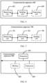
- FIG. 1 is a diagram of a communication system according to an embodiment of this application.
- the communication system includes an access network device 102, an access and mobility management function (access and mobility management function, AMF) 103, and a location management function (location management function, LMF) 104.
- AMF access and mobility management function
- LMF location management function
- a terminal device 101 is connected to the access network device 102 through an interface, the access network device is connected to the AMF 103 through an interface, and the AMF 104 is connected to the LMF 104 through an interface.
- the LMF 104 is configured to perform positioning calculation and management on a location of the terminal device 101.
- the terminal device 101 is connected to the access network device 103 through an NR-Uu interface, and the access network device 102 is connected to the AMF 103 through an NG-C interface.
- the AMF 103 is connected to the LMF 104 through an NL1 interface.
- FIG. 1 shows only an example in which the communication system includes the access network device 102.
- the communication system may further include more access network devices. This is not specifically limited in this application.
- the following describes the access network device and the terminal device that are provided in this application.
- the access network device is an apparatus deployed in a radio access network for providing a wireless communication function for the terminal device.
- the access network device may include a base station.
- the base station includes a macro base station, a micro base station (also referred to as a small cell), a relay station, an access point (access point, AP), a wearable device, an in-vehicle device, and the like in various forms.
- the base station may further include a transmission reception point (transmission reception point, TRP), a transmission measurement function (transmission measurement function, TMF), and the like.
- the base station related in this application may be a base station in new radio (new radio, NR).
- the base station in 5G NR may further include a transmission reception point (transmission reception point, TRP), a transmission point (transmission point, TP), a next generation NodeB (next Generation NodeB, gNB), or an evolved NodeB (evolved NodeB, eNB or eNodeB) in a long term evolution (long term evolution, LTE) system.
- TRP transmission reception point
- TP transmission point
- gNB next generation NodeB
- evolved NodeB evolved NodeB
- evolved NodeB, eNB or eNodeB evolved NodeB in a long term evolution (long term evolution, LTE) system.
- the terminal device is also referred to as user equipment (user equipment, UE), a mobile station (mobile station, MS), a mobile terminal (mobile terminal, MT), or the like.
- the terminal device is a device that includes a wireless communication function (providing voice/data connectivity to a user), for example, a handheld device or an in-vehicle device having a wireless connection function.
- the terminal device may include: a mobile phone (mobile phone), a tablet computer, a notebook computer, a palmtop computer, a mobile internet device (mobile internet device, MID), a wearable device, a virtual reality (virtual reality, VR) device, an augmented reality (augmented reality, AR) device, a wireless terminal in industrial control (industrial control), a wireless terminal in self driving (self driving), a wireless terminal in remote medical surgery (remote medical surgery), a wireless terminal in a smart grid (smart grid), a wireless terminal in transportation safety (transportation safety), a wireless terminal in a smart city (smart city), or a wireless terminal in a smart home (smart home).
- the AMF 103 is responsible for access control, registration management, service management, mobility management, and the like for the terminal device to access a network.
- the LMF 104 may be deployed in a core network, and is configured to perform positioning calculation and management on a location of the terminal device.
- a name of the AMF 103 may change with evolution of a communication system.
- a functional network element that has another name and that has a function similar to that of the AMF 103 may be understood as the AMF 103 in this application.
- the functional network element is applicable to the communication method provided in embodiments of this application.
- the LMF is a name in a current communication system.
- the name of the LMF may change with the evolution of the communication system. Therefore, the LMF is referred to as a location management device in the following to describe the technical solutions of this application.
- the location management device is configured to perform the positioning calculation on the location of the terminal device.
- the location management device may be deployed in an access network or the core network. This is not specifically limited in this application.
- a functional network element that has another name and that has a function similar to that of the location management device may be understood as the location management device in this application.
- the functional network element is applicable to the communication method provided in this application.
- the three RRC states are respectively: an RRC connected (RRC connected) state, an RRC inactive (RRC inactive) state, and an RRC idle (RRC idle) state.
- RRC connected state There is an RRC connection between a terminal device and an access network device, and a connection between the access network device and a core network is established for the terminal device.
- the access network device stores a UE context of the terminal device.
- the access network device and the terminal device can send a unicast message through the RRC connection.
- RRC inactive state An RRC connection between a terminal device and an access network device is suspended (suspended), and a connection between the access network device and a core network is established for the terminal device.
- the access network device stores a UE context of the terminal device.
- the terminal device may receive a broadcast message and a paging message. The paging message is initiated by the access network device.
- RRC idle state No RRC connection is established between a terminal device and an access network device, and no connection between the access network device and a core network is established for the terminal device.
- the access network device does not have a UE context of the terminal device.
- the terminal device may receive a broadcast message and a paging message. The paging message is initiated by the core network.
- Scenarios to which embodiments of this application are applicable include but are not limited to an uplink positioning scenario, a downlink positioning scenario, and an uplink/downlink positioning scenario. This is not specifically limited in this application.
- a positioning capability of the terminal device is related to an RRC state of the terminal device.
- a positioning capability of the terminal device in the RRC connected state may be understood as a conventional positioning capability of the terminal device.
- a positioning capability of the terminal device in the RRC inactive state is different from the positioning capability of the terminal device in the RRC connected state.
- a positioning capability of the terminal device in an RRC idle state is also different from the positioning capability of the terminal device in the RRC inactive state or the RRC connected state.
- the terminal device has a plurality of positioning capabilities at different levels.
- the positioning capabilities at different levels meet different positioning requirements, namely, different positioning precision.
- the positioning capabilities at different levels may be reflected as capabilities of sending an SRS by the terminal device.
- precision of measurement results obtained by the access network device is also different, and precision of location results obtained by the location management device through calculation of the measurement results of the access network device is also different.
- the location management device requests the access network device to determine an SRS configuration for the terminal device.
- the access network device determines the SRS configuration of the terminal device, and the access network device autonomously determines a state of the terminal device. For example, the access network device releases the terminal device from the RRC connected state to the RRC inactive state, so that the terminal device sends the SRS in the RRC inactive state.
- the location management device does not sense the state of the terminal device.
- the access network device autonomously determines the state of the terminal device. For example, the access network device releases the terminal device from the RRC connected state to the RRC inactive state when the terminal device has no service.
- the positioning capability of the terminal device in the RRC inactive state may be lower than the positioning capability of the terminal device in the RRC connected state. Therefore, precision of measuring a positioning reference signal (positioning reference signal, PRS) by the terminal device is limited, and downlink measurement precision is limited. Consequently, the positioning precision does not meet the positioning requirement of the location management device.
- PRS positioning reference signal
- FIG. 2 is a diagram of an embodiment of a communication method according to an embodiment of this application. Refer to FIG. 2 .
- the communication method includes the following steps.
- a terminal device determines capability information, where the capability information includes a low power capability (low power capability).
- the low power capability indicates that the terminal device supports low power positioning. For example, positioning power caused by the low power positioning performed by the terminal device is lower than positioning power caused by positioning performed by the terminal device in an RRC connected state.
- the low power positioning may be represented as: Power consumption of sending an SRS by the terminal device is lower than power consumption of sending the SRS by the terminal device in the RRC connected state.
- the low power positioning may be represented as: Power consumption of measuring a PRS by the terminal device is lower than power consumption of measuring the PRS by the terminal device in the RRC connected state.
- the low power capability indicates that the terminal device supports sending of the SRS in low power.
- the low power capability indicates that the terminal device supports receiving of the PRS in low power.
- the low power capability may also be described as a reduced capability (reduced capability), a capability when power saving (capability when power saving), a low capability, a power efficient capability (power efficient capability), a capability in a power efficient mode (capability in power efficient mode), a low power positioning capability, a reduced positioning capability, a positioning capability when power saving, or the like.
- reduced capability reduced capability
- capability when power saving capability when power saving
- low capability capability when power saving
- power efficient capability power efficient capability
- capability in a power efficient mode capability in power efficient mode
- a low power positioning capability a reduced positioning capability when power saving, or the like.
- the name is not specifically limited in this application.
- this application defines a new positioning capability, namely, the low power capability, that is different from a defined positioning capability (which may be understood as a positioning capability of the terminal device in the RRC connected state) of the terminal device.
- a defined positioning capability which may be understood as a positioning capability of the terminal device in the RRC connected state
- the low power capability may be understood as a positioning capability of the terminal device in an RRC inactive state or an RRC idle state.
- the capability information further includes the defined positioning capability of the terminal device.
- the technical solution of this application is described by using an example in which the low power capability of the terminal device is defined.
- a plurality of levels of positioning capabilities of the terminal device may be defined. Positioning capabilities at different levels may be positioning capabilities of the terminal device in different RRC states. This is not specifically limited in this application.
- the following mainly describes the technical solutions of this application by using the low power capability of the terminal device and the defined positioning capability of the terminal device as an example.
- the low power capability includes at least one of the following: a maximum quantity of SRS resources or SRS resource sets, an SRS bandwidth, and an SRS sending periodicity that are supported by the terminal device.
- the low power capability may be reflected as: the maximum quantity of SRS resources or SRS resource sets, the SRS bandwidth, and the SRS sending periodicity whose measurement is supported by the terminal device.
- the low power capability may have a smaller maximum quantity of SRS resources or SRS resource sets supported by the terminal device, and/or a smaller SRS bandwidth supported by the terminal device, and/or a longer SRS sending periodicity supported by the terminal device (this is because a capability of sending the SRS by the terminal device is poor, an occupied SRS resource is small, an occupied SRS bandwidth is small, and an SRS sending periodicity is long).
- description of the low power capability may also be replaced with a low power uplink capability, a reduced uplink capability, or a power-saving uplink capability.
- the low power capability includes at least one of the following: that the terminal device supports measurement of a positioning reference signal in the RRC inactive state, a supported positioning method, a supported PRS bandwidth, and a maximum quantity of processing resources supported in one slot.
- the low power capability may be reflected as a capability of the terminal device to process the PRS.
- the low power capability may have fewer positioning methods supported by the terminal device, and/or a smaller supported PRS bandwidth, and/or a smaller maximum quantity of processing resources supported in one slot.
- the low power capability may include capabilities of different positioning methods in the low power, for example, a low power downlink time difference of arrival (downlink time difference of arrival, DL-TDOA) capability and a low power downlink angle of departure (downlink angle of departure, DL-AOD) capability.
- the low power capability may also be referred to as a reduced capability, and specifically includes reduced capabilities of different positioning methods, for example, a reduced DL-TDOA capability and a reduced DL-AOD capability.
- the low power capability may also be referred to as the capability when power saving, and specifically includes capabilities of different positioning methods when power saving, for example, a DL-TDOA capability when power saving and a DL-AOD capability when power saving.
- the terminal device may report, to a location management device through the capability information, content included in the low power capability in the uplink positioning scenario and a content included in the low power capability in the downlink positioning scenario. This is not specifically limited in this application.
- the terminal device sends the capability information of the terminal device to the location management device.
- the location management device receives the capability information from the terminal device.
- the capability information of the terminal device includes the low power capability.
- the capability information further includes the defined positioning capability of the terminal device.
- the location management device is an LMF.
- the terminal device sends the capability information of the terminal device to the location management device through a long term evolution positioning protocol (long term evolution positioning protocol, LPP) message.
- LPP long term evolution positioning protocol
- Information carried in the LPP message is transparently transmitted to the access network device, in other words, the terminal device transparently transmits the capability information to the location management device through the LPP message.
- the location management device obtains the capability information through the LPP message.
- the terminal device sends a provide capability (provide capability) message to the location management device, where the provide capability message includes the capability information of the terminal device.
- the location management device sends first information to the access network device.
- the first information includes at least one of the following: the capability information and first indication information.
- the access network device receives the first information from the location management device.
- the first indication information is used to recommend that the low power positioning be performed on the terminal device, or indicates that the terminal device has a low power requirement.
- the first indication information may be alternatively described as or replaced with a low power indication, a low capability indication, a power saving indication, or a reduction indication.
- the location management device may analyze whether the low power capability of the terminal device can meet a positioning requirement of the location management device (for example, the positioning requirement includes positioning precision, a positioning delay, and the like). If the positioning requirement can be met, the location management device may send the first information to the access network device.
- a positioning requirement for example, the positioning requirement includes positioning precision, a positioning delay, and the like.
- the low power capability includes at least one of the following: the maximum quantity of SRS resources or SRS resource sets, the SRS bandwidth, and the SRS sending periodicity that are supported by the terminal device.
- the location management device determines that a configuration included in the low power capability can meet the positioning requirement of the location management device, and the location management device may send the first information to the access network device.
- the low power capability includes at least one of the following: that the terminal device supports the measurement of the positioning reference signal in the RRC inactive state, the supported positioning method, the supported PRS bandwidth, and the maximum quantity of processing resources supported in one slot.
- the location management device determines that a configuration included in the low power capability can meet the positioning requirement of the location management device, and the location management device may send the first information to the access network device.
- the location management device may not send the first information to the access network device.
- the access network device may configure the terminal device to be in the RRC connected state, to ensure the positioning requirement of the location management device.
- the access network device may autonomously determine an RRC state of the terminal device in an existing manner. This is not specifically limited in this application.
- the first information includes the capability information
- the location management device indirectly recommends, through the low power capability in the capability information, that the low power positioning be performed on the terminal device, or indirectly prompts, through the low power capability in the capability information, to perform the low power positioning on the terminal device.
- the first information includes the first indication information
- the location management device directly recommends, through the first indication information, that the low power positioning be performed on the terminal device, or indirectly prompts, through the first indication information, to perform the low power positioning on the terminal device.
- the first information includes the capability information and the first indication information.
- the location management device notifies, through the capability information, the access network device that the terminal device has the low power positioning capability.
- the location management device directly recommends, through the first indication information, that the low power positioning be performed on the terminal device, or indirectly prompts, through the first indication information, to perform the low power positioning on the terminal device.
- the first indication information indicates or prompts the access network device to perform the low power positioning on the terminal device. Further, the access network device may autonomously determine whether to perform the low power positioning on the terminal device.
- this application is applicable to the uplink positioning scenario, and is also applicable to the downlink positioning scenario.
- the first information is carried on different carriers.
- FIG. 3 and FIG. 4 Details are not described herein again.
- the first information further includes at least one of the following: UE measurement information and UE reporting information.
- the UE measurement information is measurement information used by the terminal device to measure a PRS, for example, a periodicity of measuring the PRS by the terminal device and a time length of measuring the PRS each time.
- the UE reporting information is information used by the terminal device to report a measurement result, for example, a periodicity in which the terminal device reports the measurement result.
- the location management device sends the first information to the access network device through a new radio positioning protocol A (new radio positioning protocol A, NRPPa) message.
- the access network device may obtain the first information through the NRPPa message.
- the access network device keeps the terminal device in the RRC connected state or the RRC inactive state based on the first information, or releases the terminal device from the RRC connected state to the RRC idle state or the RRC inactive state based on the first information.
- the access network device determines the low power capability of the terminal device based on the first information.
- the access network device keeps the terminal device in the RRC connected state or the RRC inactive state based on a relationship between the low power capability and the RRC state of the terminal device and the current RRC state of the terminal device, or releases the terminal device from the RRC connected state to the RRC idle state or the RRC inactive state based on a relationship between the low power capability and the RRC state of the terminal device and the current RRC state of the terminal device.
- the terminal device is currently in the RRC connected state. If the low power capability is the positioning capability of the terminal device in the RRC idle state or the RRC inactive state, the access network device may send an RRC release message to the terminal device, where the RRC release message is used to release the terminal device to the RRC idle state or the RRC inactive state. Correspondingly, the terminal device receives the RRC release message from the access network device. The terminal device may determine the RRC state of the terminal device through the RRC release message.
- the terminal device is currently in the RRC inactive state. If the low power capability is the positioning capability of the terminal device in the RRC inactive state, the access network device may keep the terminal device in the RRC inactive state.
- the terminal device is currently in the RRC connected state. If the low power capability is the positioning capability of the terminal device in the RRC connected state, the access network device may keep the terminal device in the RRC connected state.
- the access network device may properly configure the state of the terminal device through the first information, to implement the low power positioning of the terminal device and ensure a positioning precision requirement of the location management device.
- step 204 is a possible implementation.
- the terminal device is currently in the RRC inactive state.
- the access network device may send the RRC release message to the terminal device, where the RRC release message indicates the terminal device to release to the RRC idle state.
- the terminal device receives the RRC release message from the access network device.
- the terminal device may determine the RRC state of the terminal device through the RRC release message. Specifically, if the low power capability is the positioning capability of the terminal device in the RRC idle state, the access network device may delete a UE context of the terminal device.
- the terminal device determines the capability information, where the capability information includes the low power capability, and the low power capability indicates that the terminal device supports the low power positioning. Then, the terminal device sends the capability information to the location management device. It can be learned that, the terminal device may report the low power capability to the location management device, so that the location management device determines that the terminal device supports the low power positioning. This helps the location management device notify the access network device that the terminal device supports the low power positioning or an indication, helps the location management device indicate the access network device to perform the low power positioning on the terminal device, or helps the location management device indicate, to the access network device, that the terminal device has the low power requirement.
- the access network device may properly configure the RRC state (the RRC connected state, the RRC idle state, or the RRC inactive state) of the terminal device based on the first information. In this way, the terminal device can participate in a positioning process in the RRC state configured by the access network device. Therefore, a positioning precision requirement is ensured while the low power positioning of the terminal device is implemented, to meet a positioning service requirement of the location management device.
- the low power capability is the positioning capability of the terminal device in the RRC inactive state, and the access network device may configure the terminal device to be in the RRC inactive state.
- the terminal device can participate in the positioning process in the inactive state, so that the low power positioning of the terminal device is implemented, to ensure the precision of positioning by the location management device on the terminal device.
- Step 202 above may be replaced with:
- the terminal device sends second information to the location management device, where the second information indicates that the terminal device supports the low power capability, or the second information indicates the low power capability supported by the terminal device.
- the second information indicates that the terminal device supports the low power capability
- the second information indicates the low power capability supported by the terminal device.
- the second information may be indication information. For example, when a value of the indication information is "1", it indicates that the terminal device supports the low power capability. When the indication information is "0", it indicates that the terminal device does not support the low power capability.
- the second information may be the indication information.
- the value of the indication information is "0" it indicates that the terminal device supports a first-level low power capability.
- the value of the indication information is "1" it indicates that the terminal device supports a second-level low power capability.
- the indication information may further have more values, and these values correspond to more levels of low power capabilities.
- the indication information may further have more values, and these values correspond to more levels of low power capabilities.
- the first-level low power capability in comparison with the positioning capability of the terminal device in the RRC connected state, the first-level low power capability has a smaller quantity of maximum SRS resources or SRS resource sets supported by the terminal device, a smaller supported SRS bandwidth, and the like.
- the first-level low power capability may be an uplink positioning capability of the terminal device in the RRC inactive state.
- the second-level low power capability has a smaller quantity of maximum SRS resources or SRS resource sets supported by the terminal device, a smaller supported SRS bandwidth, and the like.
- the second-level low power capability may be an uplink positioning capability of the terminal device in the RRC idle state.
- the first-level low power capability in comparison with the positioning capability of the terminal device in the RRC connected state, the first-level low power capability has a smaller PRS bandwidth supported by the terminal device, a smaller maximum quantity of processing resources supported in one slot, and the like.
- the first-level low power capability may be a downlink positioning capability of the terminal device in the RRC inactive state.
- the second-level low power capability has a smaller PRS bandwidth supported by the terminal device, a smaller maximum quantity of processing resources supported in one slot, and the like.
- the second-level low power capability may be the downlink positioning capability of the terminal device in the RRC idle state.
- FIG. 3 is a diagram of another embodiment of a communication method according to an embodiment of this application. Refer to FIG. 3 .
- the communication method includes the following steps.
- a terminal device determines capability information, where the capability information includes a low power capability.
- the terminal device sends the capability information to a location management device.
- the location management device receives the capability information from the terminal device.
- Step 301 and step 302 are similar to step 201 and step 202 in the embodiment shown in FIG. 2 above. For details, refer to related descriptions of step 301 and step 302 above. Details are not described herein again.
- the location management device sends first information to an access network device.
- the first information includes at least one of the following: capability information and first indication information.
- the access network device receives the first information from the location management device.
- Step 303 is similar to step 203 in the embodiment shown in FIG. 2 above. For details, refer to related descriptions of step 203 in the embodiment shown in FIG. 2 above.
- step 303 above specifically includes:
- the location management device sends a positioning information request (positioning information request) to the access network device, where the positioning information request includes the first information.
- the access network device receives the positioning information request from the location management device.
- the first indication information may alternatively be described as or replaced with assistance information (assistance information), and the assistance information is used to recommend that low power positioning be performed on the terminal device.
- the location management device recommends, in a form of the assistance information to the access network device, that the low power positioning be performed on the terminal device, or indicates that the terminal device has a low power requirement.
- the positioning information request may further include more recommended configuration information.
- the location management device recommends an SRS configuration determined by the access network device for the terminal device, for example, an SRS sending periodicity or an SRS resource.
- the access network device keeps the terminal device in an RRC connected state or an RRC inactive state based on the first information, or releases the terminal device from an RRC connected state to an RRC idle state or an RRC inactive state based on the first information.
- Step 304 is similar to step 204 in the embodiment shown in FIG. 2 above. For details, refer to related descriptions of step 204 in the embodiment shown in FIG. 2 above. Details are not described herein again.
- Step 305 to step 307 may be performed after step 303.
- the access network device determines the SRS configuration for the terminal device.
- the SRS configuration includes at least one of the following: an SRS resource or an SRS resource set, an SRS bandwidth, and an SRS sending periodicity that are configured by the access network device for the terminal device.
- the location management device sends the first information to the access network device through the positioning information request.
- the positioning information request further includes recommended configuration information, a positioning service requirement, and the like.
- the access network device may determine the SRS configuration for the terminal device based on information, for example, the recommended configuration information and the positioning service requirement.
- the access network device determines the SRS configuration for the terminal device based on the first information.
- the access network device determines the low power capability of the terminal device based on the first information. Then, the access network device determines a maximum quantity of SRS resources or SRS resource sets, an SRS bandwidth, and an SRS sending periodicity that are supported by the terminal device in the low power capability. The access network device may determine the SRS configuration for the terminal device based on the information.
- the location management device sends the first information through the positioning information request.
- the location management device further includes recommended configuration information, service requirement information, and the like.
- the access network device may further determine the SRS configuration based on the recommended configuration information and the service requirement information.
- the access network device properly configures an RRC state of the terminal device.
- the access network device may determine the SRS configuration for the terminal device based on the first information, so that the access network device determines an appropriate SRS configuration for the terminal device based on the low power capability of the terminal device. For example, the access network device allocates the appropriate SRS resource for the terminal device, and configures an appropriate SRS sending periodicity, so that the SRS configuration matches the positioning capability that is set by the access network device for the terminal device in the RRC state in step 304. This avoids a problem of resource waste or resource insufficiency and improves resource utilization while ensuring positioning precision.
- the access network device sends the SRS configuration to the terminal device.
- the terminal device receives the SRS configuration from the access network device.
- the access network device sends the SRS configuration to the terminal device through an RRC message.
- step 304 when the access network device releases the terminal device to the RRC inactive state or the RRC idle state, the access network device may send the RRC release message to the terminal device.
- the RRC release message further includes the SRS configuration in step 306.
- the access network device releases the terminal device to the RRC inactive state or the RRC idle state through the RRC release message, and further delivers the SRS configuration to the terminal device.
- step 304 and step 306 may be combined into: The access network device sends the RRC release message to the terminal device, where the RRC release message is used to release the terminal device to the RRC inactive state or the RRC idle state, and the RRC release message includes the SRS configuration.
- the access network device sends the SRS configuration to the location management device.
- the location management device receives the SRS configuration from the terminal device.
- step 307 above specifically includes:
- the access network device sends a positioning information response (positioning information response) to the location management device, where the positioning information response includes the SRS configuration.
- the location management device receives a positioning information response from the access network device.
- Step 304 may be first performed, and then step 305 to step 307 are performed; step 305 to step 307 are first performed, and then step 304 is performed; or step 304 and step 305 to step 307 are simultaneously performed based on a case. This is not specifically limited in this application.
- the location management device may select the access network device configured to measure an SRS of the terminal device, and send measurement requests to such access network devices.
- the measurement request includes the SRS configuration.
- These access network devices may measure the SRS of the terminal device to obtain measurement results, and separately report the respective measurement results to the location management device.
- the location management device calculates a location of the terminal device based on the measurement results of these access network devices, to position the terminal device.
- the embodiment shown in FIG. 3 shows a specific process in which the technical solution of this application is applied to the uplink positioning scenario.
- the access network device properly configures the RRC state of the terminal device based on the first information.
- the terminal device has different positioning capabilities in different RRC states. Therefore, the access network device properly configures the state of the terminal device, to ensure an uplink positioning precision requirement of the location management device while implementing the low power positioning on the terminal device. This avoids a problem that an uplink positioning requirement of the location management device cannot be met because the access network device autonomously determines the RRC state of the terminal device without the location management device.
- FIG. 4 is a diagram of another embodiment of a communication method according to an embodiment of this application. Refer to FIG. 4 .
- the communication method includes the following steps.
- a terminal device determines capability information, where the capability information includes a low power capability.
- the terminal device sends the capability information to a location management device.
- the location management device receives the capability information from the terminal device.
- Step 401 and step 402 are similar to step 201 and step 202 in the embodiment shown in FIG. 2 above. For details, refer to related descriptions of step 401 and step 402 above. Details are not described herein again.
- the location management device sends first information to an access network device.
- the first information includes at least one of the following: the capability information and first indication information.
- the access network device receives the first information from the location management device.
- Step 403 is similar to step 203 in the embodiment shown in FIG. 2 above. For details, refer to related descriptions of step 203 in the embodiment shown in FIG. 2 above.
- the access network device keeps the terminal device in an RRC connected state or an RRC inactive state based on the first information, or releases the terminal device from an RRC connected state to an RRC idle state or an RRC inactive state based on the first information.
- Step 404 is similar to step 204 in the embodiment shown in FIG. 2 above. For details, refer to related descriptions of step 204 in the embodiment shown in FIG. 2 above. Details are not described herein again.
- the embodiment shown in FIG. 4 further includes step 405 and step 406.
- Step 405 and step 406 may be performed after step 403.
- the location management device determines TRP configuration information based on the capability information.
- the TRP configuration information includes PRS configuration information of a TRP.
- the capability information includes the low power capability.
- the low power capability includes at least one of the following: that the terminal device supports measurement of a positioning reference signal in the RRC inactive state, a supported positioning method, a supported PRS bandwidth, and a maximum quantity of processing resources supported in one slot.
- the location management device may select an appropriate TRP based on the low power capability.
- the location management device may further select the appropriate TRP based on a service requirement. This helps the terminal device measure PRSs sent by such TRPs. This avoids a waste of PRS resources or a shortage of PRS resources, so that a downlink positioning precision requirement of the location management device is met.
- the location management device sends the TRP configuration information to the terminal device.
- the location management device sends assistance data (assistance data) to the terminal device, where the assistance data includes the TRP configuration information.
- the terminal device receives the assistance data from the location management device.
- the embodiment shown in FIG. 4 further includes step 407 and step 408.
- Step 407 and step 408 may be performed after step 405.
- the location management device sends the TRP configuration information to the access network device.
- the access network device receives the TRP configuration information from the location management device.
- the location management device sends a PRS configuration request (PRS configuration request) to the access network device, where the PRS configuration request includes the TRP configuration information.
- the access network device receives the PRS configuration request from the location management device.
- the access network device sends a PRS configuration response (PRS configuration response) to the location management device.
- the location management device receives the PRS configuration response from the access network device.
- the PRS configuration response is used to notify the location management device that the access network device receives the TRP configuration information.
- the access network device sends a PRS based on the TRP configuration information.
- the location management device may further send the TRP configuration information, for example, the PRS configuration information, to the another access network device.
- the location management device may also send the PRS configuration information to the another access network device through the PRS configuration request.
- the another access network device may feed back, to the location management device through a TRP information response, that the another access network device has received the TRP configuration information.
- Step 404 may be first performed, and then step 405 to step 408 are performed; step 405 to step 408 are first performed, and then step 404 is performed; or step 404 and step 405 to step 408 are simultaneously performed based on a case. This is not specifically limited in this application.
- the location management device may send request location information (request location information) to the terminal device, where the request location information is used to request the terminal device to report a measurement result.
- the terminal device may receive PRSs sent by the TRPs selected by the location management device, and measure these PRSs to obtain the measurement results. Then, the terminal device sends the measurement results to the location management device based on provide location information (provide location information). The location management device calculates a location of the terminal device based on the measurement results, to position the terminal device.
- the embodiment shown in FIG. 4 shows a specific process in which the technical solution of this application is applied to the downlink positioning scenario.
- the access network device properly configures an RRC state of the terminal device based on the first information.
- the terminal device has different positioning capabilities in different RRC states. Therefore, the access network device properly configures the state of the terminal device, to ensure the downlink positioning precision requirement of the location management device while implementing low power positioning on the terminal device. This avoids a problem that a downlink positioning requirement of the location management device cannot be met because the access network device autonomously determines the RRC state of the terminal device without the location management device.
- FIG. 5 is a diagram of a structure of a communication apparatus 500 according to an embodiment of this application.
- the communication apparatus 500 includes a processing unit 501 and a sending unit 502.
- the communication apparatus 500 further includes a receiving unit 503.
- the communication apparatus 500 includes a terminal device or a chip in the terminal device.
- the communication apparatus 500 may be configured to perform all or some of the steps performed by the terminal device in embodiments shown in FIG. 2 to FIG. 4 .
- FIG. 2 to FIG. 4 For details, refer to related descriptions in the foregoing method embodiments shown in FIG. 2 to FIG. 4 .
- the processing unit 501 is configured to determine capability information, where the capability information includes a low power capability, and the low power capability indicates that the communication apparatus 500 supports low power positioning.
- the sending unit 502 is configured to send the capability information to a location management device.
- the low power capability includes at least one of the following: a maximum quantity of SRS resources or SRS resource sets, an SRS bandwidth, and an SRS sending periodicity that are supported by the communication apparatus 500.
- the low power capability includes at least one of the following: that the communication apparatus 500 supports measurement of a PRS in an RRC inactive state, a supported positioning method, a supported PRS bandwidth, and a maximum quantity of processing resources supported in one slot.
- the receiving unit 503 is configured to receive an RRC release message from an access network device, where the RRC release message is used to release the communication apparatus 500 from an RRC connected state to the RRC inactive state or an RRC idle state.
- the receiving unit 503 is configured to receive TRP configuration information from the location management device, where the TRP configuration information is determined by the location management device based on the capability information.
- the receiving unit 503 is configured to receive an SRS configuration from the access network device, where the SRS configuration is determined by the access network device for the communication apparatus 500 based on the capability information.
- FIG. 6 is a diagram of a structure of a communication apparatus 600 according to an embodiment of this application.
- the communication apparatus 600 includes a receiving unit 601 and a sending unit 602.
- the communication apparatus 600 further includes a processing unit 603.
- the communication apparatus 600 includes a location management device or a chip in the location management device.
- the communication apparatus 600 may be configured to perform all or some of the steps performed by the location management device in embodiments shown in FIG. 2 to FIG. 4 .
- FIG. 2 to FIG. 4 For details, refer to related descriptions in the foregoing method embodiments shown in FIG. 2 to FIG. 4 .
- the receiving unit 601 is configured to receive capability information from a terminal device, where the capability information includes a low power capability, and the low power capability indicates that the terminal device supports low power positioning.
- the sending unit 602 is configured to send first information to an access network device, where the first information includes at least one of the following: capability information and first indication information, the first indication information is used to recommend that low power positioning be performed on the terminal device, and the access network device is a serving access network device of the terminal device.
- the low power capability includes at least one of the following: a maximum quantity of SRS resources or SRS resource sets, an SRS bandwidth, and an SRS sending periodicity that are supported by the terminal device.
- the first information is carried in a positioning information request.
- the receiving unit 601 is further configured to: receive an SRS configuration from the access network device, where the SRS configuration is determined by the access network device for the terminal device based on the first information.
- the SRS configuration is carried in a positioning information response.
- the low power capability includes at least one of the following: that the terminal device supports measurement of a PRS in the RRC inactive state, a supported positioning method, a supported PRS bandwidth, and a maximum quantity of processing resources supported in one slot.
- the first information further includes at least one of the following: UE measurement information and UE reporting information, the UE measurement information is measurement information used by the terminal device to measure the positioning reference signal, and the UE reporting information is information used by the terminal device to report a measurement result.
- processing unit 603 is configured to determine TRP configuration information based on the capability information; and the sending unit 602 is further configured to:
- FIG. 7 is a diagram of a structure of a communication apparatus 700 according to an embodiment of this application.
- the communication apparatus 700 includes a receiving unit 701 and a processing unit 702.
- the communication apparatus 700 further includes a sending unit 703.
- the communication apparatus 700 includes an access network device or a chip in an access network device.
- the communication apparatus 700 may be configured to perform all or some of the steps performed by the access network device in embodiments shown in FIG. 2 to FIG. 4 .
- FIG. 2 to FIG. 4 For details, refer to related descriptions in the foregoing method embodiments shown in FIG. 2 to FIG. 4 .
- a receiving unit 701 is configured to receive first information from a location management device, where the first information includes at least one of the following: capability information of a terminal device and first indication information, the capability information includes a low power capability, the low power capability indicates that the terminal device supports low power positioning, the first indication information is used to recommend that the low power positioning be performed on the terminal device, and the communication apparatus is a serving access network device of the terminal device; and
- a processing unit 702 is configured to keep the terminal device in an RRC connected state or an RRC inactive state based on the first information, or release the terminal device from the RRC connected state to the RRC inactive state or an RRC idle state based on the first information.
- the low power capability includes at least one of the following: a maximum quantity of SRS resources or SRS resource sets, an SRS bandwidth, and an SRS sending periodicity that are supported by the terminal device.
- the first information is carried in a positioning information request.
- the processing unit 702 is further configured to: determine an SRS configuration for the terminal device based on the first information.
- the sending unit 703 is configured to send the SRS configuration to the terminal device, send a positioning information response to the location management device, where the positioning information response includes the SRS configuration.
- the low power capability includes at least one of the following: that the terminal device supports measurement of a PRS in the RRC inactive state, a supported positioning method, a supported PRS bandwidth, and a maximum quantity of processing resources supported in one slot.
- the first information further includes at least one of the following: UE measurement information and UE reporting information, the UE measurement information is measurement information used by the terminal device to measure the positioning reference signal, and the UE reporting information is information used by the terminal device to report a measurement result.
- the processing unit 702 is specifically configured to: if the low power capability is a positioning capability of the terminal device in the RRC inactive state or the RRC idle state, send an RRC release message to the terminal device, where the RRC release message is used to release the terminal device from the RRC connected state to the RRC inactive state or the RRC idle state.
- the receiving unit 701 is further configured to: receive TRP configuration information of the location management device, where the TRP configuration information is determined by the location management device based on the capability information.
- FIG. 8 is another diagram of a structure of a communication apparatus 800 according to an embodiment of this application.
- the communication apparatus 800 includes a processor 801.
- the communication apparatus 800 further includes a memory 802 and a transceiver 803.
- the processor 801, the memory 802, and the transceiver 803 are separately connected through a bus, and the memory stores computer instructions.
- the communication apparatus 800 may be configured to perform the steps performed by the terminal device in embodiments shown in FIG. 2 to FIG. 4 .
- the communication apparatus 800 may be configured to perform the steps performed by the terminal device in embodiments shown in FIG. 2 to FIG. 4 .
- the processing unit 501 shown in FIG. 5 above may be specifically the processor 801.
- the sending unit 502 and the receiving unit 503 shown in FIG. 5 above may be specifically the transceiver 803. Therefore, specific implementation of the transceiver 803 is not described again.
- the communication apparatus 800 may be configured to perform the steps performed by the location management device in embodiments shown in FIG. 2 to FIG. 4 .
- the communication apparatus 800 may be configured to perform the steps performed by the location management device in embodiments shown in FIG. 2 to FIG. 4 .
- the receiving unit 601 and the sending unit 602 shown in FIG. 6 above may be specifically the transceiver 803. Therefore, specific implementation of the transceiver 803 is not described again.
- the processing unit 803 shown in FIG. 6 above may be specifically the processor 801. Therefore, specific implementation of the processor 801 is not described again.
- the communication apparatus 800 may be configured to perform the steps performed by the access network device in embodiments shown in FIG. 2 to FIG. 4 .
- the steps performed by the access network device in embodiments shown in FIG. 2 to FIG. 4 .
- the receiving unit 701 and the sending unit 703 shown in FIG. 7 above may be specifically the transceiver 803. Therefore, specific implementation of the transceiver 803 is not described again.
- the processing unit 702 shown in FIG. 7 above may be specifically the processor 801. Therefore, specific implementation of the processor 801 is not described again.
- An embodiment of this application further provides a communication system.
- the communication system includes the terminal device, the location management device, and the access network device.
- the terminal device is configured to perform all or some of the steps performed by the terminal device in embodiments shown in FIG. 2 to FIG. 4 .
- the location management device is configured to perform all or some of the steps performed by the location management device in embodiments shown in FIG. 2 to FIG. 4 .
- the access network device is configured to perform all or some of the steps performed by the access network device in embodiments shown in FIG. 2 to FIG. 4 .
- An embodiment of this application further provides a computer program product including computer instructions.
- the computer program product runs on a computer, the computer is enabled to perform the communication method in embodiments shown in FIG. 2 to FIG. 4 .
- An embodiment of this application further provides a computer-readable storage medium, including computer instructions.
- the computer instructions When the computer instructions are run on a computer, the computer is enabled to perform the communication method in embodiments shown in FIG. 2 to FIG. 4 .
- An embodiment of this application further provides a chip apparatus, including a processor, configured to invoke a computer program or computer instructions stored in a memory, so that the processor performs the communication method in embodiments shown in FIG. 2 to FIG. 4 .
- the processor is coupled to the memory through an interface.
- the chip apparatus further includes the memory, and the memory stores a computer program or the computer instructions.
- the processor mentioned in any of the foregoing may be a general central processing unit, a microprocessor, an application-specific integrated circuit (application-specific integrated circuit, ASIC), or one or more of integrated circuits configured to control program execution of the communication method in embodiments shown in FIG. 2 and FIG. 4 .
- the memory mentioned anywhere above may be a read-only memory (read-only memory, ROM), another type of static storage device that can store static information and instructions, a random access memory (random access memory, RAM), or the like.
- the apparatus embodiments described above are merely examples.
- the units described as separate parts may or may not be physically separate, and parts displayed as units may or may not be physical units, in other words, may be located in one position, or may be distributed on a plurality of network units.
- Some or all of the modules may be selected based on actual requirements to achieve the objectives of the solutions of embodiments.
- connection relationships between modules indicate that the modules have communication connections with each other, which may be specifically implemented as one or more communication buses or signal cables.
- this application may be implemented by software in addition to necessary universal hardware, or by dedicated hardware, including a dedicated integrated circuit, a dedicated CPU, a dedicated memory, a dedicated component, and the like.
- any functions that can be performed by a computer program can be easily implemented by using corresponding hardware.
- a specific hardware structure used to achieve a same function may be in various forms, for example, in a form of an analog circuit, a digital circuit, or a dedicated circuit.
- software program implementation is a better implementation in most cases. Based on such an understanding, the technical solutions of this application essentially or the part contributing to the conventional technology may be implemented in a form of a software product.
- the computer software product is stored in a readable-storage medium, for example, a floppy disk, a USB flash drive, a removable hard disk, a ROM, a RAM, a magnetic disk, or an optical disc of a computer, and includes several instructions for instructing a computer device to perform the methods in embodiments of this application.
- a readable-storage medium for example, a floppy disk, a USB flash drive, a removable hard disk, a ROM, a RAM, a magnetic disk, or an optical disc of a computer, and includes several instructions for instructing a computer device to perform the methods in embodiments of this application.
- the computer program product includes one or more computer instructions. When the computer program instructions are loaded and executed on a computer, all or some of the procedures or functions according to embodiments of this application are generated.
- the computer may be a general-purpose computer, a dedicated computer, a computer network, or other programmable apparatuses.
- the computer instructions may be stored in a computer-readable storage medium or transmitted from one computer-readable storage medium to another computer-readable storage medium. For example, the computer instructions may be transmitted from a website, computer, network device, or local computing device, computing device, or data center through a wired network.
- the computer-readable storage medium may be any usable medium that can be stored by a computer, or a data storage device, for example, a network device, a local computing device, or a data center, integrating one or more usable media.
- the usable medium may be a magnetic medium (for example, a floppy disk, a hard disk, or a magnetic tape), an optical medium (for example, a digital video disc (digital video disc, DVD)), or a semiconductor medium (for example, a solid state disk (solid state disk, SSD)), or the like.
- a magnetic medium for example, a floppy disk, a hard disk, or a magnetic tape
- an optical medium for example, a digital video disc (digital video disc, DVD)
- a semiconductor medium for example, a solid state disk (solid state disk, SSD)
- sequence numbers of the foregoing processes do not mean execution sequences in various embodiments of this application.
- the execution sequences of the processes should be determined according to functions and internal logic of the processes, and should not be construed as any limitation on the implementation processes of embodiments of this application.
- the disclosed system, apparatus, and method may be implemented in other manners.
- the described apparatus embodiment is merely an example.
- division into the units is merely logical function division and may be other division in actual implementation.
- a plurality of units or components may be combined or integrated into another system, or some features may be ignored or not performed.
- displayed or discussed mutual couplings or direct couplings or communication connections may be implemented through some interfaces. Indirect couplings or communication connections between the apparatuses or the units may be implemented in electrical, mechanical, or other forms.
- the units described as separate parts may or may not be physically separate, and parts displayed as units may or may not be physical units, in other words, may be located in one position, or may be distributed on a plurality of network units. Some or all of the units may be selected based on actual requirements to achieve the objectives of the solutions of embodiments.
- functional units in embodiments of this application may be integrated into one processing unit, or each of the units may exist alone physically, or two or more units are integrated into one unit.
- the integrated unit may be implemented in a form of hardware, or may be implemented in a form of a software functional unit.
- the integrated unit When the integrated unit is implemented in the form of a software functional unit and sold or used as an independent product, the integrated unit may be stored in a computer-readable storage medium.
- the technical solutions of this application essentially, a part contributing to the current technology, or all or some of the technical solutions may be implemented in a form of a software product.
- the software product is stored in a storage medium, and includes several instructions for instructing a computer device (which may be a personal computer, a server, a network device, or the like) to perform all or some of the steps of the methods described in embodiments of this application.
Landscapes
- Engineering & Computer Science (AREA)
- Signal Processing (AREA)
- Computer Networks & Wireless Communication (AREA)
- Databases & Information Systems (AREA)
- Mobile Radio Communication Systems (AREA)
Applications Claiming Priority (2)
| Application Number | Priority Date | Filing Date | Title |
|---|---|---|---|
| CN202210129935.4A CN116634352A (zh) | 2022-02-11 | 2022-02-11 | 通信方法以及通信装置 |
| PCT/CN2023/075146 WO2023151612A1 (zh) | 2022-02-11 | 2023-02-09 | 通信方法以及通信装置 |
Publications (2)
| Publication Number | Publication Date |
|---|---|
| EP4468752A1 true EP4468752A1 (de) | 2024-11-27 |
| EP4468752A4 EP4468752A4 (de) | 2025-04-23 |
Family
ID=87563636
Family Applications (1)
| Application Number | Title | Priority Date | Filing Date |
|---|---|---|---|
| EP23752392.3A Pending EP4468752A4 (de) | 2022-02-11 | 2023-02-09 | Kommunikationsverfahren und kommunikationsvorrichtung |
Country Status (4)
| Country | Link |
|---|---|
| US (1) | US20240397473A1 (de) |
| EP (1) | EP4468752A4 (de) |
| CN (1) | CN116634352A (de) |
| WO (1) | WO2023151612A1 (de) |
Cited By (1)
| Publication number | Priority date | Publication date | Assignee | Title |
|---|---|---|---|---|
| US20250175884A1 (en) * | 2023-05-30 | 2025-05-29 | Quectel Wireless Solutions Co., Ltd. | Method for communication, positioning server, access network device, and terminal device |
Family Cites Families (3)
| Publication number | Priority date | Publication date | Assignee | Title |
|---|---|---|---|---|
| CN101801072B (zh) * | 2010-02-02 | 2012-09-05 | 华为终端有限公司 | 提供低功耗服务的方法和设备及通信系统 |
| CN111586811B (zh) * | 2019-02-18 | 2023-08-15 | 中国移动通信有限公司研究院 | 一种信息处理方法和终端 |
| CN113973260B (zh) * | 2020-07-22 | 2023-08-01 | 大唐移动通信设备有限公司 | 上行信号定位的方法、通信基站和测量基站及ue |
-
2022
- 2022-02-11 CN CN202210129935.4A patent/CN116634352A/zh active Pending
-
2023
- 2023-02-09 WO PCT/CN2023/075146 patent/WO2023151612A1/zh not_active Ceased
- 2023-02-09 EP EP23752392.3A patent/EP4468752A4/de active Pending
-
2024
- 2024-08-07 US US18/796,582 patent/US20240397473A1/en active Pending
Cited By (2)
| Publication number | Priority date | Publication date | Assignee | Title |
|---|---|---|---|---|
| US20250175884A1 (en) * | 2023-05-30 | 2025-05-29 | Quectel Wireless Solutions Co., Ltd. | Method for communication, positioning server, access network device, and terminal device |
| US12550046B2 (en) * | 2023-05-30 | 2026-02-10 | Quectel Wireless Solutions Co., Ltd. | Method for communication, positioning server, access network device, and terminal device |
Also Published As
| Publication number | Publication date |
|---|---|
| WO2023151612A1 (zh) | 2023-08-17 |
| CN116634352A (zh) | 2023-08-22 |
| EP4468752A4 (de) | 2025-04-23 |
| US20240397473A1 (en) | 2024-11-28 |
Similar Documents
| Publication | Publication Date | Title |
|---|---|---|
| EP3952355A1 (de) | Kommunikationsverfahren und -vorrichtung | |
| EP3993527B1 (de) | Kommunikationsverfahren und -vorrichtungen | |
| KR20210008053A (ko) | 통신 방법 및 통신 장치 | |
| US20200213903A1 (en) | Data transmission method and device | |
| CN113038577A (zh) | 一种控制信息的传输方法及设备 | |
| US20170164281A1 (en) | Secondary cell group configuration | |
| US20240276271A1 (en) | Expedited measurement reporting (xmr) | |
| US12562872B2 (en) | Communication method and related apparatus for positioning an electronic device | |
| WO2021036925A1 (zh) | 通信方法及装置 | |
| EP3468292A1 (de) | Übergangsverfahren und vorrichtung zur übertragungsmodus | |
| US10708765B2 (en) | Method and apparatus for indicating restricted resources of wireless terminal | |
| WO2019228459A1 (zh) | 通信方法、装置及存储介质 | |
| CN116684947A (zh) | 一种节能小区的唤醒方法和装置、设备、可读存储介质 | |
| WO2025113119A1 (zh) | 发送方法、接收方法、装置、设备及存储介质 | |
| US20240397473A1 (en) | Communication method and communication apparatus | |
| US12581568B2 (en) | Communication method and related apparatus thereof | |
| US20240022380A1 (en) | Communication method and apparatus | |
| EP4510690A1 (de) | Verfahren, vorrichtung und speichermedium zur aufzeichnung von sdt-ereignissen | |
| EP4539585A1 (de) | Verbindungssteuerungsverfahren, -vorrichtung und -system | |
| EP4462856A1 (de) | Kommunikationsverfahren und kommunikationsvorrichtung | |
| EP3579616A1 (de) | Umschaltverfahren, vorrichtung und system | |
| US20210144630A1 (en) | Base station and data transmission method thereof for mobile communication system | |
| CN108323242A (zh) | 切换方法、设备及系统 | |
| CN114554555B (zh) | 一种小区切换方法及装置、基站 | |
| EP4373169A1 (de) | Kommunikationsverarbeitungsverfahren und kommunikationsverarbeitungsvorrichtung |
Legal Events
| Date | Code | Title | Description |
|---|---|---|---|
| STAA | Information on the status of an ep patent application or granted ep patent |
Free format text: STATUS: THE INTERNATIONAL PUBLICATION HAS BEEN MADE |
|
| PUAI | Public reference made under article 153(3) epc to a published international application that has entered the european phase |
Free format text: ORIGINAL CODE: 0009012 |
|
| STAA | Information on the status of an ep patent application or granted ep patent |
Free format text: STATUS: REQUEST FOR EXAMINATION WAS MADE |
|
| 17P | Request for examination filed |
Effective date: 20240823 |
|
| AK | Designated contracting states |
Kind code of ref document: A1 Designated state(s): AL AT BE BG CH CY CZ DE DK EE ES FI FR GB GR HR HU IE IS IT LI LT LU LV MC ME MK MT NL NO PL PT RO RS SE SI SK SM TR |
|
| A4 | Supplementary search report drawn up and despatched |
Effective date: 20250325 |
|
| RIC1 | Information provided on ipc code assigned before grant |
Ipc: H04W 76/27 20180101ALI20250320BHEP Ipc: H04W 64/00 20090101ALI20250320BHEP Ipc: H04W 52/02 20090101ALI20250320BHEP Ipc: H04W 8/24 20090101ALI20250320BHEP Ipc: H04W 4/02 20180101AFI20250320BHEP |
|
| DAV | Request for validation of the european patent (deleted) | ||
| DAX | Request for extension of the european patent (deleted) |