EP4468719A1 - Video generation method and apparatus based on multiple vehicle-mounted cameras, and vehicle-mounted device - Google Patents
Video generation method and apparatus based on multiple vehicle-mounted cameras, and vehicle-mounted device Download PDFInfo
- Publication number
- EP4468719A1 EP4468719A1 EP23742871.9A EP23742871A EP4468719A1 EP 4468719 A1 EP4468719 A1 EP 4468719A1 EP 23742871 A EP23742871 A EP 23742871A EP 4468719 A1 EP4468719 A1 EP 4468719A1
- Authority
- EP
- European Patent Office
- Prior art keywords
- video
- vehicle
- board
- sequences
- clarity
- Prior art date
- Legal status (The legal status is an assumption and is not a legal conclusion. Google has not performed a legal analysis and makes no representation as to the accuracy of the status listed.)
- Granted
Links
Images


Classifications
-
- H—ELECTRICITY
- H04—ELECTRIC COMMUNICATION TECHNIQUE
- H04N—PICTORIAL COMMUNICATION, e.g. TELEVISION
- H04N21/00—Selective content distribution, e.g. interactive television or video on demand [VOD]
- H04N21/80—Generation or processing of content or additional data by content creator independently of the distribution process; Content per se
- H04N21/85—Assembly of content; Generation of multimedia applications
- H04N21/854—Content authoring
- H04N21/8547—Content authoring involving timestamps for synchronizing content
-
- B—PERFORMING OPERATIONS; TRANSPORTING
- B60—VEHICLES IN GENERAL
- B60R—VEHICLES, VEHICLE FITTINGS, OR VEHICLE PARTS, NOT OTHERWISE PROVIDED FOR
- B60R1/00—Optical viewing arrangements; Real-time viewing arrangements for drivers or passengers using optical image capturing systems, e.g. cameras or video systems specially adapted for use in or on vehicles
- B60R1/20—Real-time viewing arrangements for drivers or passengers using optical image capturing systems, e.g. cameras or video systems specially adapted for use in or on vehicles
- B60R1/22—Real-time viewing arrangements for drivers or passengers using optical image capturing systems, e.g. cameras or video systems specially adapted for use in or on vehicles for viewing an area outside the vehicle, e.g. the exterior of the vehicle
- B60R1/23—Real-time viewing arrangements for drivers or passengers using optical image capturing systems, e.g. cameras or video systems specially adapted for use in or on vehicles for viewing an area outside the vehicle, e.g. the exterior of the vehicle with a predetermined field of view
- B60R1/27—Real-time viewing arrangements for drivers or passengers using optical image capturing systems, e.g. cameras or video systems specially adapted for use in or on vehicles for viewing an area outside the vehicle, e.g. the exterior of the vehicle with a predetermined field of view providing all-round vision, e.g. using omnidirectional cameras
-
- H—ELECTRICITY
- H04—ELECTRIC COMMUNICATION TECHNIQUE
- H04N—PICTORIAL COMMUNICATION, e.g. TELEVISION
- H04N21/00—Selective content distribution, e.g. interactive television or video on demand [VOD]
- H04N21/20—Servers specifically adapted for the distribution of content, e.g. VOD servers; Operations thereof
- H04N21/23—Processing of content or additional data; Elementary server operations; Server middleware
- H04N21/234—Processing of video elementary streams, e.g. splicing of video streams or manipulating encoded video stream scene graphs
- H04N21/23418—Processing of video elementary streams, e.g. splicing of video streams or manipulating encoded video stream scene graphs involving operations for analysing video streams, e.g. detecting features or characteristics
-
- H—ELECTRICITY
- H04—ELECTRIC COMMUNICATION TECHNIQUE
- H04N—PICTORIAL COMMUNICATION, e.g. TELEVISION
- H04N21/00—Selective content distribution, e.g. interactive television or video on demand [VOD]
- H04N21/20—Servers specifically adapted for the distribution of content, e.g. VOD servers; Operations thereof
- H04N21/23—Processing of content or additional data; Elementary server operations; Server middleware
- H04N21/234—Processing of video elementary streams, e.g. splicing of video streams or manipulating encoded video stream scene graphs
- H04N21/23424—Processing of video elementary streams, e.g. splicing of video streams or manipulating encoded video stream scene graphs involving splicing one content stream with another content stream, e.g. for inserting or substituting an advertisement
-
- H—ELECTRICITY
- H04—ELECTRIC COMMUNICATION TECHNIQUE
- H04N—PICTORIAL COMMUNICATION, e.g. TELEVISION
- H04N21/00—Selective content distribution, e.g. interactive television or video on demand [VOD]
- H04N21/20—Servers specifically adapted for the distribution of content, e.g. VOD servers; Operations thereof
- H04N21/23—Processing of content or additional data; Elementary server operations; Server middleware
- H04N21/234—Processing of video elementary streams, e.g. splicing of video streams or manipulating encoded video stream scene graphs
- H04N21/2343—Processing of video elementary streams, e.g. splicing of video streams or manipulating encoded video stream scene graphs involving reformatting operations of video signals for distribution or compliance with end-user requests or end-user device requirements
- H04N21/234345—Processing of video elementary streams, e.g. splicing of video streams or manipulating encoded video stream scene graphs involving reformatting operations of video signals for distribution or compliance with end-user requests or end-user device requirements the reformatting operation being performed only on part of the stream, e.g. a region of the image or a time segment
-
- H—ELECTRICITY
- H04—ELECTRIC COMMUNICATION TECHNIQUE
- H04N—PICTORIAL COMMUNICATION, e.g. TELEVISION
- H04N21/00—Selective content distribution, e.g. interactive television or video on demand [VOD]
- H04N21/40—Client devices specifically adapted for the reception of or interaction with content, e.g. set-top-box [STB]; Operations thereof
- H04N21/41—Structure of client; Structure of client peripherals
- H04N21/414—Specialised client platforms, e.g. receiver in car or embedded in a mobile appliance
- H04N21/41422—Specialised client platforms, e.g. receiver in car or embedded in a mobile appliance located in transportation means, e.g. personal vehicle
-
- H—ELECTRICITY
- H04—ELECTRIC COMMUNICATION TECHNIQUE
- H04N—PICTORIAL COMMUNICATION, e.g. TELEVISION
- H04N21/00—Selective content distribution, e.g. interactive television or video on demand [VOD]
- H04N21/40—Client devices specifically adapted for the reception of or interaction with content, e.g. set-top-box [STB]; Operations thereof
- H04N21/41—Structure of client; Structure of client peripherals
- H04N21/422—Input-only peripherals, i.e. input devices connected to specially adapted client devices, e.g. global positioning system [GPS]
- H04N21/4223—Cameras
-
- H—ELECTRICITY
- H04—ELECTRIC COMMUNICATION TECHNIQUE
- H04N—PICTORIAL COMMUNICATION, e.g. TELEVISION
- H04N21/00—Selective content distribution, e.g. interactive television or video on demand [VOD]
- H04N21/40—Client devices specifically adapted for the reception of or interaction with content, e.g. set-top-box [STB]; Operations thereof
- H04N21/43—Processing of content or additional data, e.g. demultiplexing additional data from a digital video stream; Elementary client operations, e.g. monitoring of home network or synchronising decoder's clock; Client middleware
- H04N21/44—Processing of video elementary streams, e.g. splicing a video clip retrieved from local storage with an incoming video stream or rendering scenes according to encoded video stream scene graphs
- H04N21/44008—Processing of video elementary streams, e.g. splicing a video clip retrieved from local storage with an incoming video stream or rendering scenes according to encoded video stream scene graphs involving operations for analysing video streams, e.g. detecting features or characteristics in the video stream
-
- H—ELECTRICITY
- H04—ELECTRIC COMMUNICATION TECHNIQUE
- H04N—PICTORIAL COMMUNICATION, e.g. TELEVISION
- H04N21/00—Selective content distribution, e.g. interactive television or video on demand [VOD]
- H04N21/40—Client devices specifically adapted for the reception of or interaction with content, e.g. set-top-box [STB]; Operations thereof
- H04N21/43—Processing of content or additional data, e.g. demultiplexing additional data from a digital video stream; Elementary client operations, e.g. monitoring of home network or synchronising decoder's clock; Client middleware
- H04N21/44—Processing of video elementary streams, e.g. splicing a video clip retrieved from local storage with an incoming video stream or rendering scenes according to encoded video stream scene graphs
- H04N21/44016—Processing of video elementary streams, e.g. splicing a video clip retrieved from local storage with an incoming video stream or rendering scenes according to encoded video stream scene graphs involving splicing one content stream with another content stream, e.g. for substituting a video clip
-
- H—ELECTRICITY
- H04—ELECTRIC COMMUNICATION TECHNIQUE
- H04N—PICTORIAL COMMUNICATION, e.g. TELEVISION
- H04N21/00—Selective content distribution, e.g. interactive television or video on demand [VOD]
- H04N21/40—Client devices specifically adapted for the reception of or interaction with content, e.g. set-top-box [STB]; Operations thereof
- H04N21/43—Processing of content or additional data, e.g. demultiplexing additional data from a digital video stream; Elementary client operations, e.g. monitoring of home network or synchronising decoder's clock; Client middleware
- H04N21/44—Processing of video elementary streams, e.g. splicing a video clip retrieved from local storage with an incoming video stream or rendering scenes according to encoded video stream scene graphs
- H04N21/4402—Processing of video elementary streams, e.g. splicing a video clip retrieved from local storage with an incoming video stream or rendering scenes according to encoded video stream scene graphs involving reformatting operations of video signals for household redistribution, storage or real-time display
- H04N21/440245—Processing of video elementary streams, e.g. splicing a video clip retrieved from local storage with an incoming video stream or rendering scenes according to encoded video stream scene graphs involving reformatting operations of video signals for household redistribution, storage or real-time display the reformatting operation being performed only on part of the stream, e.g. a region of the image or a time segment
-
- H—ELECTRICITY
- H04—ELECTRIC COMMUNICATION TECHNIQUE
- H04N—PICTORIAL COMMUNICATION, e.g. TELEVISION
- H04N23/00—Cameras or camera modules comprising electronic image sensors; Control thereof
- H04N23/90—Arrangement of cameras or camera modules, e.g. multiple cameras in TV studios or sports stadiums
-
- H—ELECTRICITY
- H04—ELECTRIC COMMUNICATION TECHNIQUE
- H04N—PICTORIAL COMMUNICATION, e.g. TELEVISION
- H04N5/00—Details of television systems
- H04N5/222—Studio circuitry; Studio devices; Studio equipment
- H04N5/262—Studio circuits, e.g. for mixing, switching-over, change of character of image, other special effects ; Cameras specially adapted for the electronic generation of special effects
- H04N5/2624—Studio circuits, e.g. for mixing, switching-over, change of character of image, other special effects ; Cameras specially adapted for the electronic generation of special effects for obtaining an image which is composed of whole input images, e.g. splitscreen
-
- H—ELECTRICITY
- H04—ELECTRIC COMMUNICATION TECHNIQUE
- H04N—PICTORIAL COMMUNICATION, e.g. TELEVISION
- H04N5/00—Details of television systems
- H04N5/222—Studio circuitry; Studio devices; Studio equipment
- H04N5/262—Studio circuits, e.g. for mixing, switching-over, change of character of image, other special effects ; Cameras specially adapted for the electronic generation of special effects
- H04N5/2625—Studio circuits, e.g. for mixing, switching-over, change of character of image, other special effects ; Cameras specially adapted for the electronic generation of special effects for obtaining an image which is composed of images from a temporal image sequence, e.g. for a stroboscopic effect
Definitions
- the present application pertains to the field of intelligent vehicle technology, particularly to a method for video generation based on on-board multi-camera, a device, and a piece of on-board equipment.
- the current one-click video creation technologies mainly focus on video data collected by a single camera. Since a vehicle may be equipped with multiple cameras, each capturing different video data, the current one-click video creation technologies are not suitable for vehicular scenarios.
- One of the objectives of the present application is to provide a method for video generation based on on-board multi-camera, a device, and a piece of on-board equipment, which can process video data collected by multiple on-board cameras to create new videos, and realize the application of one-click video creation technology in vehicular scenarios.
- a device for video generation based on on-board multi-camera which includes a video data acquisition module, a video sequence extraction module, a display area determination module and a target video generation module.
- the video data acquisition module is configured to obtain video data collected separately by multiple on-board cameras installed in different orientations on a vehicle, where each of the on-board camera is configured to collect video data from a corresponding orientation.
- the video sequence extraction module is configured to extract one or more video sequences to be processed from the video data of each orientation.
- the display area determination module is configured to identify display areas of the video data from each orientation in a target video that is to be generated.
- the target video generation module is configured to combine multiple video sequences from multiple orientations based on the display areas to generate the target video.
- a piece of on-board equipment which includes a memory, a processor, and a computer program stored in the memory and executable by the processor.
- the processor when executing the computer program, is configured to implement the method for video generation based on on-board multi-camera as described in the first aspect.
- a computer-readable storage medium in which a computer program is stored, the computer program, when executed by a processor, causes the method for video generation based on on-board multi-camera as described in the first aspect to be implemented.
- a computer program product which, when running on a computer, enables the computer to execute the method for video generation based on on-board multi-camera as described in the first aspect.
- the method for video generation based on on-board multi-camera has the following beneficial effects: the on-board equipment is allowed to extract one or more video sequences to be processed from the video data of each orientation by obtaining the video data collected separately by multiple on-board cameras installed in different orientations on a vehicle. After determining display areas of the video data from each orientation in a target video to be generated, the on-board equipment is allowed to combine multiple video sequences from various orientations based on the display areas to generate the target video.
- the embodiments of the present application can combine video data collected by multiple vehicle cameras into a new target video, which addresses the issue of current one-click video creation technologies being inapplicable to the on-board multi-camera scenarios, and achieves one-click video creation for video data from multiple on-board cameras in vehicular scenarios.
- the target video generated based on the different orientations of multiple on-board cameras can offer more perspectives, can form more combination schemes and special effects, and can make the target video obtained by one-click video creation more attractive.
- One-click video creation refers to a technology where videos or images to be edited are imported with one click, and the key frames are extracted or the key images are selected through an algorithm according to a preset template to synthesize a new video in combination with effects, transitions, filters, music, and other conditions.
- One-click video creation can automatically complete video or image editing without user operations, which significantly saves the time for video and picture editing.
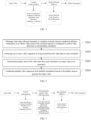
- FIG. 1 is a schematic diagram of a processing flow of a one-click video creation in the existing technologies.
- the vehicle system mainly adopts a visual algorithm to realize the content understanding, so as to extract the key frames in the video, such as, classifying scenes involved in the video, performing aesthetic evaluations, detecting significant areas, discovering and extracting highlights, etc.
- special effects are added through processes such as sticker material application, style transfer, and sky replacement, and then a final new video is created.
- this method is not suitable to vehicles equipped with multiple cameras.
- the present application provides the method for video generation based on on-board multi-camera provided, which can perform one-click video creation operations on video data captured by multiple on-board cameras to enhance video generation efficiency.
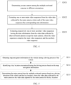
- the method particularly includes the following steps S201 to S204: S201: Obtaining video data captured separately by multiple on-board cameras installed in different orientations on a vehicle, where each of the on-board cameras is configured to capture video data from a corresponding orientation.
- This method may be applied to on-board equipment, and the on-board equipment may be electronic devices installed in various types or models of vehicles capable of processing video data.
- the on-board equipment may be an on-board computer, an on-board video processing device, etc., specific types of on-board equipment are not limited by the embodiments of the present application.
- the vehicle may be provided with multiple on-board cameras, and the multiple on-board cameras may be installed in different orientations on the vehicle.
- Each on-board camera is capable of capturing video at its respective orientation, resulting in video data from that orientation during a driving process of the vehicle.
- the multiple on-board cameras may include on-board camera(s) installed on an outer side of the vehicle as well as on-board camera(s) installed on an inner side of the vehicle.
- the on-board camera(s) installed on the outer side of the vehicle may capture external scenes during driving, and the on-board camera(s) installed on the inner side of the vehicle may capture the driver and passengers, to obtain corresponding video data.
- multiple on-board cameras may be respectively installed at the front, left front, right front, rear, left rear, right rear, left side, and right side of the vehicle.
- the on-board camera installed at the front of the vehicle may capture video of the scene in front of the vehicle during driving, and this video may be the same as what the driver and passenger actually see.
- the on-board camera installed on the right side of the vehicle may capture video of the scene to the right side of the vehicle during driving, and this video may be the same as what the driver and passenger actually see to the right.
- the on-board cameras in various orientations may all in working condition to capture videos of the scenes from various orientations, resulting in video data from those orientations.
- the on-board equipment when processing the video data collected separately by the multiple on-board cameras into a single video, may first obtain the corresponding video data from these on-board cameras.
- S202 Extracting one or more video sequences to be processed from the video data of each orientation.
- the on-board equipment when processing video data captured by multiple on-board cameras into a single video, may retain only the more critical video content from each orientation. These video contents may be composed of key video frames from their respective orientations.
- the on-board equipment after obtaining the video data from each orientation, may extract video sequences from video data of each orientation, and these video sequences are the video sequences to be processed into a new video.
- the on-board equipment when extracting video sequences from the video data captured by each on-board camera in the corresponding orientation, may extract one or more video sequences from the video data of each orientation.
- the number of video sequences extracted by the on-board equipment from each video data captured by the on-board cameras from various orientations may be equal or may be different, which is not limited in the embodiments of the present application.
- the on-board equipment when extracting one or more video sequences to be processed from the video data of each of the orientations respectively, may first perform content understanding on the video data.
- FIG. 3 which illustrates a process flow of the method for video generation based on on-board multi-camera provided by an embodiment of the present application.
- the input video in this method is the video data captured from different orientations of the vehicle by various on-board cameras.
- the on-board equipment may use methods similar to those in existing technologies, such as scene classification, aesthetic evaluation, detection of significant areas, discovery of highlights, etc. Subsequently, the on-board equipment may process the video data captured by the multiple on-board cameras, extract key frames or highlights from various video data to form the to-be-processed video sequences.
- the step S202 of extracting one or more video sequences to be processed from the video data of each of the orientations respectively may include the following sub-steps S2021-S2023.
- S2021 Determining a main camera among the multiple on-board cameras in different orientations.
- the on-board equipment may determine the main camera from multiple on-board cameras based on a driver or passenger's selection. For example, the driver may operate the on-board equipment to preselect the on-board camera installed at the front of the vehicle as the main camera. Consequently, the on-board camera in the front of the vehicle will be correspondingly set by the on-board equipment as the main camera based on the driver or passenger's selection.
- the on-board equipment may dynamically determine the main camera based on actual video contents captured by various on-board cameras. By dynamically determining the main camera, different on-board cameras may serve as the main camera over a continuous period of time. Since each on-board camera captures video from a different orientation, a main video sequence extracted from the main camera will also contain video contents in different orientations. This further enhances the diversity of the final generated target video created using the one-click video creation technique, and improves the interest of the target video.
- the step S2021 of determining the main camera from multiple on-board cameras may include the following sub-steps S211-S213: S211: Obtaining map navigation information of the vehicle during a driving process.
- the map navigation information may indicate a driving route and direction of the vehicle during the driving process.
- the map navigation information includes not only the driving route and direction but also multiple key locations along the route.
- the various key locations may be identified by the on-board equipment based on the map navigation information.
- the key locations may be the locations of famous landmarks, commercial districts, and iconic buildings.
- the on-board cameras may capture video clips at and near these key locations to obtain exciting footage.
- S213 Determining the main camera from multiple on-board cameras based on a driving direction of the vehicle and the key location, where the video data collected by the main camera will be the video data captured by the main camera for the key location.
- the on-board equipment may process the video data collected by the multiple on-board cameras using positional relationships of these multiple on-board cameras and the map navigation information. For example, the on-board equipment may determine the main camera from multiple on-board cameras based on the vehicle's driving direction and the key locations identified according to the map navigation information. Since the key locations are marked in the map navigation information, the accuracy of determining the main camera can be improved by combining the map navigation information to determine the main camera, ensuring that the video data collected by the main camera is related to key location points as much as possible, which helps the final generated target video to retain the interesting content during the driving process of the vehicle to the maximum extent and enhances the viewability of the target video.
- the on-board cameras installed on the vehicle include on-board cameras 601, 602, and 603.
- the on-board camera 601 is installed at the front right of the vehicle
- the on-board camera 602 is installed on the right side of the vehicle
- the on-board camera 603 is installed at the rear right of the vehicle.
- Point S in FIG. 6 represents a key location.
- point S represents the location of a famous landmark.
- the on-board equipment may dynamically determine the main camera from multiple on-board cameras based on the vehicle's driving direction and the key location S. For example, when the vehicle is at point A, the on-board equipment may identify the upcoming key location S according to the map navigation information. At this point, video data captured by the on-board camera 601 installed at the front right of the vehicle includes content related to the key location S. Thus, the on-board camera 601 may be set by the on-board equipment as the current main camera. As the vehicle continues to travel and reaches point B, the key location S is on the right side of the vehicle. At this point, video data captured by the on-board camera 602 installed at the right side of the vehicle includes content related to key location S.
- the on-board camera 602 may be set by the on-board equipment as the current main camera. Then, when the vehicle reaches point C, key location S is at the rear right of the vehicle. At this point, video data captured by the on-board camera 603 installed at the rear right of the vehicle includes content related to key location S. Thus, the on-board camera 603 may be set by the on-board equipment as the current main camera. By dynamically determining the main camera, it can be ensured that the video data collected by the main camera is the video data captured for the key locations.
- S2022 Extracting one or more main video sequences from the video data collected by the main camera, where each main video sequence has corresponding time information.
- the one or more main video sequences may be extracted by identifying the exciting segments within the video data captured by the main camera.
- Each main video sequence may have corresponding time information.
- FIG. 7 is a schematic diagram of a main video sequence provided by an embodiment of the present application.
- the video data shown in FIG. 7 may be the video data captured by the main camera, the video data has a duration of 60 minutes (min), or 3600 seconds (s).
- the segments from 0-5s, 13-27s, ..., 3527-3600s are the exciting segments within this video data. These exciting segments collectively form multiple main video sequences from the video data captured by the main camera.
- the exciting segments in the video data may be used as segments in the target video generated by the subsequent one-click video creation.
- the exciting segments captured by the main camera may be non-continuous video sequences over multiple periods of time.
- the proportion of non-exciting segments in the target video can be reduced, the data volume of the target video can be decreased, and the storage space required for the target video can be reduced, which is conducive to the dissemination and sharing of the target video.
- S2023 Extracting respectively one or more auxiliary video sequences having the time information from the video data collected by other on-board cameras except the main camera.
- the video sequences include main video sequences and auxiliary video sequences.
- the on-board equipment may extract one or more auxiliary video sequences having the time information shown in FIG. 7 from their respective video data.
- the duration of the video data collected by each on-board camera should be equal or approximately equal.
- the duration of the video data collected by each of the on-board cameras, including the main camera may be 60 minutes.
- the on-board equipment after extracting one or more main video sequences having time information from the video data collected by the main camera, may also extract video sequences having the same time information from the video data collected by other on-board cameras. Based on the time information of the main video sequences, auxiliary video sequences matching the main video sequences can be quickly and accurately extracted from the video data collected by other on-board cameras, which ensures time synchronization for each frame of the target video generated by one-click video creation and enhances the authenticity of the target video.
- the step S2023 of extracting respectively one or more auxiliary video sequences having the time information from the video data collected by the other on-board cameras except the main camera may include the following sub-steps S231-S233: S231: Determining respectively timestamps of a start video frame and an end video frame for each main video sequence based on the time information to obtain a timestamp sequence.
- the timestamps of the start video frame and the end video frame for each main video sequence can be determined.
- the main video sequence corresponding to 0-5s in FIG. 7 may be processed first, where the start video frame is a video frame at 0 second corresponds to a timestamp assumed to be Time1, and the end video frame is a video frame at the 5-th second corresponds to a timestamp assumed to be Time2. Then, the main video sequence corresponding to a time period from the 13-th to the 27-th second in FIG.
- a timestamp sequence can be obtained, i.e., ⁇ Time1, Time2, Time3, Time4, ..., TimeN ⁇ .
- S232 Marking the timestamp sequence in the video data collected by each of the other on-board cameras except the main camera.
- the timestamp sequence may be marked in the video data collected by each of the other on-board cameras, i.e., the video frames corresponding to various timestamps ⁇ Time1, Time2, Time3, Time4, ..., TimeN ⁇ in the video data collected by each of the other on-board cameras are marked.
- S233 Sequentially determining video sequences to be extracted from the video data marked with the timestamp sequence and extracting the video sequences to be extracted to obtain the one or more auxiliary video sequences having the time information.
- FIG. 9 is a schematic diagram showing video data marked with a timestamp sequence provided by an embodiment of the present application.
- the video sequence formed by the video frames between Time1 and Time2 have the same time information as the main video sequence from 0 to the 5-th second shown in FIG. 7 .
- the video sequence formed by the video frames between Time3 and Time4 have the same time information as the main video sequence from the 13-th to 27-th second shown in FIG. 7 .
- the video sequence formed by the video frames between Time1 and Time2 the video sequence formed by the video frames between Time3 and Time4 may be sequentially extracted until all the video sequences are extracted from the video data.
- the embodiment of the present application by extracting video sequences from the video data of other on-board cameras according to the timestamp sequence, can ensure that the extracted video sequences are consistent with the main video sequence in terms of time. Additionally, the on-board equipment can store these video sequences directly in the order these video sequences are extracted, reducing the complexity of processing these video sequences.
- S203 Determining display areas of the video data from each orientation in a target video to be generated.
- the display area of the video data from each orientation in the target video may be determined based on a video template.
- the on-board equipment may receive the video template selected for the target video to be generated. That is, the driver or passenger may select any video template from multiple video templates based on actual needs or preferences.
- Each video template may include multiple template areas, and any template area may have a binding relationship with the on-board cameras in different orientations.
- the on-board equipment may determine the display area of the video data from each orientation in the target video based on the binding relationship between the on-board camera at each orientation and the template areas.
- FIG. 10 is a schematic diagram of a video template provided by an embodiment of the embodiment of the present application.
- the video template selected by the driver or passenger may include four template areas: area I, area II, area II, and area IV
- Area I may have a binding relationship with the on-board camera on the left side of the vehicle
- area II may have a binding relationship with the on-board camera on the right side of the vehicle
- area III may have a binding relationship with the on-board camera at the front of vehicle
- area IV may have a binding relationship with the on-board camera at the rear of the vehicle.
- the new video ultimately generated by the one-click video creation will also include four display areas corresponding to the four template areas in the video template shown in FIG. 10 .
- Each display area is used to display the video data captured by the on-board camera with which the corresponding area has a binding relationship.
- the on-board equipment may combine the video sequences extracted from the video data collected by the on-board cameras from different orientations to generate the target video.
- the on-board equipment may play one or more video sequences extracted from the video data collected by the on-board camera in the corresponding orientation in each display area to generate the target video.
- the video data collected by the on-board cameras from multiple orientations may be presented to the driver, passenger, or other users in one video screen when the target video is played, which achieves the one-click video creation of the video data collected by the on-board cameras in vehicular scenarios.
- the on-board equipment may also add video effects to the target video during one-click video creation.
- video effects For example, background music, video style changes, sticker materials, filter processing of video images, weather replacement, etc., may be added to the target video.
- the embodiments of the present application do not limit how video effects are added.
- the on-board equipment by obtaining the video data collected separately by multiple on-board cameras installed in different orientations on the vehicle, can extract one or more video sequences to be processed from the video data of each orientation.
- the on-board equipment after determining the display areas of the video data from each orientation in the target video to be generated, may combine multiple video sequences from multiple orientations based on the display areas to generate the target video.
- the video data collected by multiple on-board cameras may be combined into a new target video based on the positional relationship of the on-board cameras, which solves the problem of the existing one-click video creation technology being unable to be applied to the on-board multi-camera scenarios, and realizes the one-click video creation of the video data collected by multiple on-board cameras in vehicular scenarios.
- the final generated target video can have more perspectives, forming more combination schemes and effects, which enables the target video generated by the one-click video creation to be more attractive.
- the clarity of these multiple displayed video segments may also be adjusted to ensure that high-clarity videos are presented to the user.
- the specific process is as follows: After obtaining the video sequences to be displayed within the same time using timestamp information, the clarity of the selected multiple video sequences may be identified and compared. Then, a deblurring processing is performed on the video sequence according to an identification and comparison result combined with particular vehicle information, to ensure that the clarity of the video to be displayed meets the required standards.
- the particular vehicle information has effects on the clarity of the videos captured by the on-board cameras, and the types of specific parameters of the particular vehicle information are not limited in the embodiments of the present application and can be adjusted based on different vehicle models, driving conditions, and other factors.
- particular vehicle information may include: vehicle speed information, vehicle location information, and/or the interface display size of the vehicle system or terminal equipment used for playing the target video.
- each video sequence (referred to as a target video segment) of the selected video sequences is compared with a video having a preset clarity. If the clarity of a selected video segment is lower than the preset clarity of the video for comparison, then the reason for the reduced clarity may be determined. If it is determined that the reason includes vehicle speed information, vehicle location information, etc., then these parameters along with the clarity comparison result are used as inputs to a pre-trained deblurring model for deblurring the video to be displayed. When a difference value between the clarity of the video to be displayed and the preset clarity of the video for comparison is within a first preset range, the deblurring process stops, resulting in a video ready for display that meets the clarity requirements.
- a clarity comparison is performed on the video to be displayed and the video of the preset clarity. If the clarity does not meet the requirements, the video to be displayed is processed using a deblurring model considering the factors affecting clarity, so as to ensure that the clarity of the video to be displayed meets the preset standards. This ensures high-definition video is presented to the user, enhancing video clarity and users' viewing experience.
- the clarity of the videos in different display areas may also be compared. Specifically: Multiple video segments with the same timestamp sequence from different display areas are selected and the clarity of the multiple video segments are compared one by one. Then, the comparison result and particular vehicle information are used as inputs to the pre-trained deblurring model for deblurring. When the clarity between the deblurred videos remains within a second preset range, the deblurring process is stopped, and then the video to be displayed that meets the clarity requirements is obtained.
- the clarity of the video to be displayed in each selected display area is compared.
- the clarity of the video to be displayed in each display area is adjusted for consistency, to enable the videos displayed in different areas to have the same clarity, to ensure that the overall video eventually presented to the user is in the same clarity, so as to ensure the consistency of the clarity of the video played by the display screen, and then enhance the stability of the video playback.
- matching relations among different speeds, different vehicle location information, different interface display sizes and different video deblurring models may be pre-stored by the vehicle system.
- the vehicle system after obtaining a target movement speed of the corresponding camera when shooting of the image to be processed, different vehicle location information and different interface display sizes, can determine a target video deblurring model matching the speed, vehicle location, and interface display size according to the target movement speed as well as the pre-stored matching relation between different video deblurring models and different speeds, the matching relation between different video deblurring models and different vehicle locations, the interface display size as well as and the pre-stored matching relation between different video deblurring models and different interface display sizes.
- the vehicle system may pre-build a model library for storing multiple video deblurring models, and each video deblurring model corresponds to a preset speed range, a preset location area, and an interface display size range.
- the vehicle system may find the target video deblurring model matching the target movement speed of the corresponding camera when shooting of the image to be processed, the location information and the interface display size from the pre-built model library.
- the preset speed range may be set as needed which will not be limited in here.
- the preset speed range may be (0, 30), [30, 40], (40, 50], (50, 60], (60, 70], (70, 80], (80, 90], and (90, + ⁇ ), etc., and the unit of any speed in the above speed range is km/h.
- the preset location area may be set in city streets or city attractions, such as street a in city A or attraction b in city A.
- the interface display size may be set according to the size of the current display screen in the vehicle.
- the vehicle system may determine the target speed range based on the target movement speed, then find a first target video deblurring model corresponding to the video to be processed from the pre-built model library based on the target speed range.
- the vehicle system may determine the preset location area based on the vehicle location information and find a second target video deblurring model corresponding to the video to be processed from the pre-built model library.
- the vehicle system may determine the interface display size range based on the interface display size and find a third target video deblurring model corresponding to the video to be processed from the pre-built model library.
- the video to be displayed is deblurred by using the first, second, and third target video deblurring models, to obtain three processed videos. The clarity of the three processed videos is compared, and the clearest video is selected as the final video to be displayed.
- the video deblurring model is selected based on pre-trained corresponding relations among preset speed ranges, preset location areas, and interface display sizes. Particularly: A target speed-location corresponding range is determined according to the current vehicle location information combined with the current speed. Next, a primary deblurring model for the video to be processed is found from the pre-built model library according to the speed-location corresponding range. A target display scaling ratio corresponding to the interface display size is determined based on the primary deblurring model, and the target video deblurring model is found from the pre-built model library according to the primary deblurring model and the target display scaling ratio. Then, the video to be displayed is deblurred by using this target video deblurring model to obtain the final clear video.
- the trained video deblurring model is used in combination with vehicle speed information, vehicle location information and interface display size to deblur the video to be displayed, such that it is possible to deblur the video under conditions of various speeds, locations, and display sizes. This improves the applicability of the video deblurring process to various vehicle conditions.
- the vehicle system may obtain the video deblurring model corresponding to each preset speed range through the following operations, detailed as follows: Each frame image of an original sample video corresponding to a preset speed range is obtained as an original sample image.
- the original sample image is input into a preset original image deblurring model for processing to obtain a preprocessed sample image.
- An edge detection algorithm is used to process the original sample image and the preprocessed sample image to obtain a first operator corresponding to the original sample image and a second operator corresponding to the preprocessed sample image.
- a loss function corresponding to the original sample image is calculated based on the first and second operators.
- Parameters of the original image deblurring model are optimized based on the loss function to obtain an image deblurring model corresponding to the preset speed range.
- the terminal equipment may input the original sample image corresponding to the preset speed range into the preset original image deblurring model for processing, to obtain the preprocessed sample image corresponding to the original sample image.
- the original image deblurring model may be a pre-built deep learning model, such as a Generative Adversarial Network (Deblur GAN) model.
- the terminal equipment after obtaining the pre-processed sample image, may use the edge detection algorithm to process the original sample image and the pre-processed sample image respectively, to obtain the first operator corresponding to the original sample image and the second operator corresponding to the pre-processed sample image.
- the edge detection algorithm includes, but is not limited to, Sobel edge detection algorithm, Canny edge detection algorithm, or Laplacian edge detection algorithm.
- Lsobel represents the loss function
- Predict_sobel represents the first operator corresponding to the original sample image
- Ysobel represents the second operator corresponding to the pre-processed sample image
- the terminal equipment after obtaining the loss function, may use this loss function as the backpropagation error to update network weights in the original image deblurring model. This means performing parameter optimization on the original image deblurring model based on the loss function to obtain the image deblurring model corresponding to the preset speed range.
- the image deblurring method trains the original image deblurring model corresponding to each preset speed range by inputting the original sample image into the preset original image deblurring model for processing to obtain the pre-processed sample image. Then, the edge detection algorithm is used to process the pre-processed sample image and the original sample image respectively, to obtain the first operator corresponding to the original sample image and the second operator corresponding to the pre-processed sample image. The loss function is then calculated based on the first operator and the second operator and used as the backpropagation error to optimize the parameters of the original image deblurring model.
- the image deblurring model obtained by this method can achieve higher image clarity, which further improves the image quality of the deblurred image. It should be noted that the sequence of steps in the above embodiment does not imply the order of execution; the order of execution should be determined by its function and intrinsic logic and should not impose any limitation on the implementation process of the embodiments of the present application.
- FIG. 11 shows a schematic diagram of a device for video generation based on on-board multi-camera provided by an embodiment of the present application.
- the device particularly includes a video data acquisition module 1101, a video sequence extraction module 1102, a display area determination module 1103, and a target video generation module 1104, in which:
- the video sequence extraction module 1102 may particularly be configured to: determine a main camera among the multiple on-board cameras in different orientations; extract one or more main video sequences from the video data collected by the main camera, where each main video sequence has corresponding time information; and extract respectively one or more auxiliary video sequences having the same time information from the video data collected by other on-board cameras except the main camera.
- the video sequences include the main and auxiliary video sequences.
- the video sequence extraction module 1102 may also be configured to: obtain map navigation information of the vehicle during a driving process; identify a key location encountered during the driving process based on the map navigation information; determine the main camera among the multiple on-board cameras based on a driving direction of the vehicle and the key location, where the video data collected by the main camera is the video data captured by the main camera for the key location.
- the video sequence extraction module 1102 may also be configured to: determine respectively timestamps of a start video frame and an end video frame of each main video sequence according to the time information, to obtain a timestamp sequence; mark the timestamp sequence in the video data collected by the other on-board cameras except the main camera; determine in sequence the video sequences to be extracted from the video data marked with the timestamp sequence and extract the same, to obtain one or more auxiliary video sequences having the time information.
- the display area determination module 1103 may particularly be configured to: receive a video template selected for the target video to be generated, where the video template includes multiple template areas, and any of the template areas has a binding relation to the on-board camera in different orientations of the vehicle; determine the display areas of the video data from each orientation in the target video to be generated according to the binding relations between the on-board camera in different orientations and the template areas.
- the target video generation module 1104 may particularly be configured to: play separately one or more video sequences extracted from the video data collected by the on-board cameras of the corresponding orientation in each of the display areas to generate the target video.
- the device also includes a video special effect adding module, which may particularly be configured to: add video special effects to the target video, where the video special effects include at least one of the following processing: adding background music, changing video style, adding sticker materials, applying filters to the video image, and replacing weather.
- a video special effect adding module which may particularly be configured to: add video special effects to the target video, where the video special effects include at least one of the following processing: adding background music, changing video style, adding sticker materials, applying filters to the video image, and replacing weather.
- the device also includes a video clarity processing module, which may particularly be configured to: identify and compare the video clarity of multiple video sequences; perform deblurring processing on the video sequences according to an identification and comparison result combined with particular vehicle information, to ensure that the video clarity of multiple video sequences meets preset conditions.
- a video clarity processing module which may particularly be configured to: identify and compare the video clarity of multiple video sequences; perform deblurring processing on the video sequences according to an identification and comparison result combined with particular vehicle information, to ensure that the video clarity of multiple video sequences meets preset conditions.
- the video clarity processing module may also particularly be configured to: perform clarity comparison on a target video segment and a video of a preset clarity to obtain an identification and comparison result, where the target video segment is any video segment of the multiple video sequences, and the identification and comparison result includes a relationship between the clarity of the target video segment and the preset clarity; determine a factor affecting the clarity of the target video segment if the clarity of the target video segment is less than the preset clarity; and correspondingly perform, if the factor affecting the clarity of the target video segment is the particular vehicle information, deblurring processing on the video sequences according to the identification and comparison result combined with the particular vehicle information to ensure that the video clarity of multiple video sequences meets the preset conditions.
- the video clarity processing module may also particularly be configured to: perform clarity comparison on the target video segment and the video of the preset clarity to obtain a first comparison result, where the target video segment is any video segment of the multiple video sequences, and the first comparison result includes a relationship between the clarity of the target video segment and the preset clarity; select multiple target video segments having the same timestamp sequence from different display areas; compare the video clarity of any two target video segments among the selected multiple target video segments to obtain a second comparison result, where the second comparison result includes a relationship between the video clarity of the two video segments, and the identification and comparison result includes the first comparison result and the second comparison result.
- the particular vehicle information includes a vehicle speed, vehicle location information and an interface display size.
- the video clarity processing module may also particularly be configured to: obtain the video deblurring model based on the vehicle speed of the vehicle when collecting the target video segment, the vehicle location information, and the interface display size of the display area corresponding to the target video segment, where corresponding relations among different vehicle speeds, different vehicle location information, different interface display sizes, and different video deblurring models are pre-stored; and input the comparison result and the particular vehicle information into the pre-trained video deblurring model to perform deblurring processing on the target video segment in the video sequences, to ensure that the video clarity of multiple video sequences meets the preset conditions.
- the particular vehicle information includes the vehicle speed, the vehicle location information and the interface display size.
- the video clarity processing module may also particularly be configured to perform the following operations for each target video segment in the multiple video sequences: determining, based on the vehicle speed of the vehicle when collecting the target video segment, a first video deblurring model corresponding to the vehicle speed, and using the first video deblurring model to perform deblurring processing on the target video segment to obtain a first segment video, where a relationship between different vehicle speeds and different video deblurring models is pre-stored; determining, based on the vehicle location information of the vehicle when collecting the target video segment, a second video deblurring model corresponding to the vehicle location information, and using the second video deblurring model to perform deblurring processing on the target video segment to obtain a second segment video, where a relationship between different vehicle location information and different video deblurring models is pre-stored; determining, based on the interface display size of the display area corresponding to the target video segment, a
- the video sequence extraction module 1102 may particularly be configured to determine the main camera among the multiple on-board cameras based on actual video content captured by each on-board camera.
- the video sequence extraction module 1102 may also be configured to designate, based on the driving direction of the vehicle and the key location, the on-board camera that can capture the key location as the main camera for the vehicle at this location.
- the on-board equipment 1200 in the embodiment of the present application includes: a processor 1210, a memory 1220, and a computer program 1221 stored in the memory 1220 and executable by the processor 1210.
- the processor 1210 when executing the computer program 1221, is configured to implement the steps of the method for video generation based on on-board multi-camera in various embodiments, such as the steps S201 to S204 shown in FIG. 2 .
- the processor 1210 when executing the computer program 1221, is configured to implement the functions of each module/unit in the device embodiments, such as the functions of modules 1101 to 1104 shown in FIG. 11 .
- the computer program 1221 may be divided into one or more modules/units, which are stored in the memory 1220, and executed by the processor 1210 to complete the present application.
- the one or more modules/units may be a series of computer program instruction segments capable of performing specific functions, describing the execution process of the computer program 1221 in the on-board equipment 1200.
- the computer program 1221 may be divided into a video data acquisition module, a video sequence extraction module, a display area determination module, and a target video generation module.
- the specific functions of the various modules are as follows:
- the on-board equipment 1200 may be the on-board computer, on-board video processing device, or other equipment mentioned in the foregoing embodiments.
- the on-board equipment 1200 may include, but not limited to, the processor 1210 and the memory 1220.
- FIG. 12 is merely an exemplary representation of the on-board equipment 1200 and does not constitute a limitation on the on-board equipment 1200.
- the on-board equipment may include more or fewer components than shown, combine some components, or include different components.
- the on-board equipment 1200 may also include input/output devices, network access devices, buses, and so on.
- the processor 1210 may be a central processing unit (Central Processing Unit, CPU) or other general-purpose processors, digital signal processors (Digital Signal Processor, DSP), application-specific integrated circuits, (Application-Specific Integrated Circuit, ASIC), field-programmable gate arrays (Field-Programmable Gate Array, FPGA), other programmable logic devices, discrete gate or transistor logic devices, discrete hardware components, etc.
- a general-purpose processor may be a microprocessor or any conventional processor.
- the memory 1220 may be an internal storage unit of the on-board equipment 1200, such as a hard disk or memory of the on-board equipment 1200.
- the memory 1220 may also be an external storage device of the on-board equipment 1200, such as a plug-in hard disk, a smart media card (Smart Media Card, SMC), a secure digital (Secure Digital, SD) card, a flash card (Flash Card), etc., equipped on the on-board equipment 1200.
- the memory 1220 may include both internal storage units and external storage devices of the on-board equipment 1200.
- the memory 1220 is configured to store the computer program 1221 and other programs and data required by the on-board equipment 1200.
- the memory 1220 may also be configured to temporarily store data that has been output or will be output.
- An embodiment of the present application also provides a piece of on-board equipment including a memory, a processor, and a computer program stored in the memory and executable by the processor.
- the processor when executing the computer program, is configured to implement the method for video generation based on on-board multi-camera as described in the previous embodiments.
- An embodiment of the present application also provides a computer-readable storage medium storing a computer program.
- the computer program when executed by a processor, causes the method for video generation based on on-board multi-camera as described in the previous embodiments to be implemented.
- An embodiment of the present application also provides a computer program product.
- the computer program product when running on a computer, enables the computer to execute the method for video generation based on on-board multi-camera as described in the previous embodiments.
- the various functions implemented by the on-board equipment in the embodiment of the present application may be stored in a computer-readable storage medium. Based on this understanding, all or part of the processes in the method embodiments may be completed by instructing related hardware through a computer program.
- the computer program may be stored in a computer-readable storage medium, which, when executed by a processor, enables the steps in the method embodiments to be implemented.
- the computer program includes computer program code, which may be in the form of source code, object code, executable files, or some intermediate form.
- the computer-readable medium may at least include any entity or device capable of carrying computer program code to a video generation device/on-board equipment based on on-board multi-camera, recording media, a computer storage, a read-only memory (Read-Only Memory, ROM), a random-access memory (Random Access Memory, RAM), electrical carrier signals, telecommunications signals, and software distribution media, such as USB drives, mobile hard drives, magnetic disks, or optical discs.
- computer-readable media do not include electrical carrier signals and telecommunications signals according to legislative and patent practices.
- the disclosed device/on-board equipment and method may be implemented in other ways.
- the described device/on-board equipment embodiments are merely illustrative.
- the division of modules or units is just a logical function division. Actual implementation may have other division methods, such as combining multiple units or components or integrating them into another system, or some features may be ignored or not executed.
- the coupling or direct coupling or communication connection between the illustrated or discussed elements may be indirect coupling or communication connection through some interface, device, or unit, and may be in electrical, mechanical, or other forms.
- the units described as separate components may be or may not be physically separated.
- Components shown as units may be or may not be physical units, i.e., these components may be located in one place or distributed across multiple network units. Some or all of the units may be selected to achieve the purposes of this embodiment according to actual needs.
Landscapes
- Engineering & Computer Science (AREA)
- Multimedia (AREA)
- Signal Processing (AREA)
- Mechanical Engineering (AREA)
- Computer Security & Cryptography (AREA)
- Business, Economics & Management (AREA)
- Marketing (AREA)
- Closed-Circuit Television Systems (AREA)
Abstract
Description
- This application claims priority to the
Chinese patent application No. 202210055793.1, filed on January 18, 2022 - The present application pertains to the field of intelligent vehicle technology, particularly to a method for video generation based on on-board multi-camera, a device, and a piece of on-board equipment.
- In the field of intelligent vehicles, cameras installed on vehicles enable video capture functionalities, which provides the possibility for the application of one-click video creation technology in this domain. However, the current one-click video creation technologies mainly focus on video data collected by a single camera. Since a vehicle may be equipped with multiple cameras, each capturing different video data, the current one-click video creation technologies are not suitable for vehicular scenarios.
- One of the objectives of the present application is to provide a method for video generation based on on-board multi-camera, a device, and a piece of on-board equipment, which can process video data collected by multiple on-board cameras to create new videos, and realize the application of one-click video creation technology in vehicular scenarios.
- Technical solutions adopted in the embodiments of the present application may be as follows:
In accordance with a first Aspect, a method for video generation based on on-board multi-camera is provided, which includes the following steps: - obtaining video data collected separately by multiple on-board cameras installed in different orientations on a vehicle, where each of the on-board cameras is configured collect video data from a corresponding orientation;
- extracting one or more video sequences to be processed from the video data of each orientation;
- determining display areas of the video data from each orientation in a target video to be generated; and
- combining multiple video sequences from multiple orientations based on the display areas to generate the target video.
- In accordance with a second aspect, a device for video generation based on on-board multi-camera is provided, which includes a video data acquisition module, a video sequence extraction module, a display area determination module and a target video generation module.
- The video data acquisition module is configured to obtain video data collected separately by multiple on-board cameras installed in different orientations on a vehicle, where each of the on-board camera is configured to collect video data from a corresponding orientation.
- The video sequence extraction module is configured to extract one or more video sequences to be processed from the video data of each orientation.
- The display area determination module is configured to identify display areas of the video data from each orientation in a target video that is to be generated.
- The target video generation module is configured to combine multiple video sequences from multiple orientations based on the display areas to generate the target video.
- In accordance with a third aspect, a piece of on-board equipment is provided, which includes a memory, a processor, and a computer program stored in the memory and executable by the processor. The processor, when executing the computer program, is configured to implement the method for video generation based on on-board multi-camera as described in the first aspect.
- In accordance with a fourth aspect, a computer-readable storage medium is provided, in which a computer program is stored, the computer program, when executed by a processor, causes the method for video generation based on on-board multi-camera as described in the first aspect to be implemented.
- In accordance with a fifth aspect, a computer program product is provided, which, when running on a computer, enables the computer to execute the method for video generation based on on-board multi-camera as described in the first aspect.
- The method for video generation based on on-board multi-camera provided by embodiments of the present application has the following beneficial effects: the on-board equipment is allowed to extract one or more video sequences to be processed from the video data of each orientation by obtaining the video data collected separately by multiple on-board cameras installed in different orientations on a vehicle. After determining display areas of the video data from each orientation in a target video to be generated, the on-board equipment is allowed to combine multiple video sequences from various orientations based on the display areas to generate the target video. Based on the positional relationship of the on-board cameras, the embodiments of the present application can combine video data collected by multiple vehicle cameras into a new target video, which addresses the issue of current one-click video creation technologies being inapplicable to the on-board multi-camera scenarios, and achieves one-click video creation for video data from multiple on-board cameras in vehicular scenarios. Meanwhile, the target video generated based on the different orientations of multiple on-board cameras can offer more perspectives, can form more combination schemes and special effects, and can make the target video obtained by one-click video creation more attractive.
- To illustrate the technical solutions in the embodiments of the present application more clearly, the following is a brief introduction of the drawings that need to be used in the embodiments or exemplary technologies. It is evident that the drawings described below are merely examples of certain embodiments of the present application. Persons skilled in the art can derive other drawings without exerting creative effort based on these drawings.
-
FIG. 1 is a schematic diagram of a processing flow of a one-click video creation in the existing technologies; -
FIG. 2 is a schematic diagram of a method for video generation based on on-board multi-camera provided in an embodiment of the present application; -
FIG. 3 is a schematic diagram of a processing flow of the method for video generation based on on-board multi-camera provided in an embodiment of the present application; -
FIG. 4 is a schematic diagram illustrating an implementation of step S202 in the method for video generation based on on-board multi-camera provided in an embodiment of the present application; -
FIG. 5 is a schematic diagram illustrating an implementation of step S2021 in the method for video generation based on on-board multi-camera provided in an embodiment of the present application; -
FIG. 6 is a schematic diagram illustrating an example of determining a main camera provided in an embodiment of the present application; -
FIG. 7 is a schematic diagram showing a main video sequence provided in an embodiment of the present application; -
FIG. 8 is a schematic diagram illustrating an implementation of step S2023 in the method for video generation based on on-board multi-camera provided in an embodiment of the present application; -
FIG. 9 is a schematic diagram showing video data marked with a timestamp sequence provided in an embodiment of the present application; -
FIG. 10 is a schematic diagram of a video template provided in an embodiment of the present application; -
FIG. 11 is a schematic diagram of a device for video generation based on on-board multi-camera provided in an embodiment of the present application; and -
FIG. 12 is a schematic diagram of a piece of on-board equipment provided in an embodiment of the present application. - To make the objectives, technical solutions, and advantages of the present application more comprehensible and clearer, detailed explanations are further provided below in conjunction with the drawings and embodiments. It should be understood that the specific embodiments described herein are intended only to explain the invention and are not intended to limit the present application.
- It should be noted that when a component is described as being "fixed to" or "disposed on" another component, it may be directly or indirectly on the other component. When a component is described as being "connected to" another component, it may be directly or indirectly connected to the other component. The terms "upper," "lower," "left," "right," etc., indicating orientation or positional relationships are based on the orientations or positions shown in the drawings, merely for convenience of description, and are not intended to indicate or imply specific orientations or constructions of the described devices or elements, and thus should not be construed as limitations of the present application. For persons skilled in the art, the specific meanings of these terms can be understood based on specific circumstances. The terms "first," "second," etc., are used only for descriptive purposes and should not be construed as indicating relative importance or implicitly specifying the number of features. The word "multiple" means two or more unless otherwise expressly specified.
- One-click video creation refers to a technology where videos or images to be edited are imported with one click, and the key frames are extracted or the key images are selected through an algorithm according to a preset template to synthesize a new video in combination with effects, transitions, filters, music, and other conditions. One-click video creation can automatically complete video or image editing without user operations, which significantly saves the time for video and picture editing.
- As shown in
FIG. 1 , which is a schematic diagram of a processing flow of a one-click video creation in the existing technologies. According to the processing flow shown inFIG. 1 , for the input video, the vehicle system mainly adopts a visual algorithm to realize the content understanding, so as to extract the key frames in the video, such as, classifying scenes involved in the video, performing aesthetic evaluations, detecting significant areas, discovering and extracting highlights, etc. On this basis, special effects are added through processes such as sticker material application, style transfer, and sky replacement, and then a final new video is created. However, this method is not suitable to vehicles equipped with multiple cameras. In view of this, the present application provides the method for video generation based on on-board multi-camera provided, which can perform one-click video creation operations on video data captured by multiple on-board cameras to enhance video generation efficiency. - The following provides a detailed explanation of the technical solutions of the present application through specific embodiments.
- Referring to
FIG. 2 , which illustrates a method for video generation based on on-board multi-camera provided by an embodiment of the present application, the method particularly includes the following steps S201 to S204:
S201: Obtaining video data captured separately by multiple on-board cameras installed in different orientations on a vehicle, where each of the on-board cameras is configured to capture video data from a corresponding orientation. - This method may be applied to on-board equipment, and the on-board equipment may be electronic devices installed in various types or models of vehicles capable of processing video data. For example, the on-board equipment may be an on-board computer, an on-board video processing device, etc., specific types of on-board equipment are not limited by the embodiments of the present application.
- In an embodiment of the present application, the vehicle may be provided with multiple on-board cameras, and the multiple on-board cameras may be installed in different orientations on the vehicle. Each on-board camera is capable of capturing video at its respective orientation, resulting in video data from that orientation during a driving process of the vehicle. Particularly, the multiple on-board cameras may include on-board camera(s) installed on an outer side of the vehicle as well as on-board camera(s) installed on an inner side of the vehicle. Herein, the on-board camera(s) installed on the outer side of the vehicle may capture external scenes during driving, and the on-board camera(s) installed on the inner side of the vehicle may capture the driver and passengers, to obtain corresponding video data.
- For example, multiple on-board cameras may be respectively installed at the front, left front, right front, rear, left rear, right rear, left side, and right side of the vehicle. Herein, the on-board camera installed at the front of the vehicle may capture video of the scene in front of the vehicle during driving, and this video may be the same as what the driver and passenger actually see. Similarly, the on-board camera installed on the right side of the vehicle may capture video of the scene to the right side of the vehicle during driving, and this video may be the same as what the driver and passenger actually see to the right.
- In an embodiment of the present application, during the driving process of the vehicle, the on-board cameras in various orientations may all in working condition to capture videos of the scenes from various orientations, resulting in video data from those orientations. The on-board equipment, when processing the video data collected separately by the multiple on-board cameras into a single video, may first obtain the corresponding video data from these on-board cameras.
- S202: Extracting one or more video sequences to be processed from the video data of each orientation.
- In an embodiment of the present application, the on-board equipment, when processing video data captured by multiple on-board cameras into a single video, may retain only the more critical video content from each orientation. These video contents may be composed of key video frames from their respective orientations. Thus, the on-board equipment, after obtaining the video data from each orientation, may extract video sequences from video data of each orientation, and these video sequences are the video sequences to be processed into a new video.
- It should be noted that, the on-board equipment, when extracting video sequences from the video data captured by each on-board camera in the corresponding orientation, may extract one or more video sequences from the video data of each orientation. The number of video sequences extracted by the on-board equipment from each video data captured by the on-board cameras from various orientations may be equal or may be different, which is not limited in the embodiments of the present application.
- In one possible implementation of the present application, in the step S202, the on-board equipment, when extracting one or more video sequences to be processed from the video data of each of the orientations respectively, may first perform content understanding on the video data.
- As shown in
FIG. 3 , which illustrates a process flow of the method for video generation based on on-board multi-camera provided by an embodiment of the present application. Unlike the existing one-click video creation process shown inFIG. 1 , the input video in this method is the video data captured from different orientations of the vehicle by various on-board cameras. For content understanding of the input video, the on-board equipment may use methods similar to those in existing technologies, such as scene classification, aesthetic evaluation, detection of significant areas, discovery of highlights, etc. Subsequently, the on-board equipment may process the video data captured by the multiple on-board cameras, extract key frames or highlights from various video data to form the to-be-processed video sequences. - In another possible implementation of the present application, as shown in
FIG. 4 , the step S202 of extracting one or more video sequences to be processed from the video data of each of the orientations respectively may include the following sub-steps S2021-S2023. - S2021: Determining a main camera among the multiple on-board cameras in different orientations.
- In an embodiment of the present application, the on-board equipment may determine the main camera from multiple on-board cameras based on a driver or passenger's selection. For example, the driver may operate the on-board equipment to preselect the on-board camera installed at the front of the vehicle as the main camera. Consequently, the on-board camera in the front of the vehicle will be correspondingly set by the on-board equipment as the main camera based on the driver or passenger's selection.
- Alternatively, the on-board equipment may dynamically determine the main camera based on actual video contents captured by various on-board cameras. By dynamically determining the main camera, different on-board cameras may serve as the main camera over a continuous period of time. Since each on-board camera captures video from a different orientation, a main video sequence extracted from the main camera will also contain video contents in different orientations. This further enhances the diversity of the final generated target video created using the one-click video creation technique, and improves the interest of the target video.
- In one possible implementation of the present application, as shown in
FIG. 5 , the step S2021 of determining the main camera from multiple on-board cameras may include the following sub-steps S211-S213:
S211: Obtaining map navigation information of the vehicle during a driving process. - In an embodiment of the present application, the map navigation information may indicate a driving route and direction of the vehicle during the driving process.
- S212: Identifying a key location encountered during the driving process based on the map navigation information.
- Generally, the map navigation information includes not only the driving route and direction but also multiple key locations along the route. The various key locations may be identified by the on-board equipment based on the map navigation information.
- In an embodiment of the present application, the key locations may be the locations of famous landmarks, commercial districts, and iconic buildings. The on-board cameras may capture video clips at and near these key locations to obtain exciting footage.
- S213: Determining the main camera from multiple on-board cameras based on a driving direction of the vehicle and the key location, where the video data collected by the main camera will be the video data captured by the main camera for the key location.
- As shown in
FIG. 3 , the on-board equipment may process the video data collected by the multiple on-board cameras using positional relationships of these multiple on-board cameras and the map navigation information. For example, the on-board equipment may determine the main camera from multiple on-board cameras based on the vehicle's driving direction and the key locations identified according to the map navigation information. Since the key locations are marked in the map navigation information, the accuracy of determining the main camera can be improved by combining the map navigation information to determine the main camera, ensuring that the video data collected by the main camera is related to key location points as much as possible, which helps the final generated target video to retain the interesting content during the driving process of the vehicle to the maximum extent and enhances the viewability of the target video. - As shown in
FIG. 6 , which illustrates an example of determining the main camera. The on-board cameras installed on the vehicle include on-board cameras board camera 601 is installed at the front right of the vehicle, the on-board camera 602 is installed on the right side of the vehicle, and the on-board camera 603 is installed at the rear right of the vehicle. As the vehicle travels on the road, it passes through points A, B, and C, moving from point A towards point C. Point S inFIG. 6 represents a key location. For example, point S represents the location of a famous landmark. - The on-board equipment may dynamically determine the main camera from multiple on-board cameras based on the vehicle's driving direction and the key location S. For example, when the vehicle is at point A, the on-board equipment may identify the upcoming key location S according to the map navigation information. At this point, video data captured by the on-
board camera 601 installed at the front right of the vehicle includes content related to the key location S. Thus, the on-board camera 601 may be set by the on-board equipment as the current main camera. As the vehicle continues to travel and reaches point B, the key location S is on the right side of the vehicle. At this point, video data captured by the on-board camera 602 installed at the right side of the vehicle includes content related to key location S. Thus, the on-board camera 602 may be set by the on-board equipment as the current main camera. Then, when the vehicle reaches point C, key location S is at the rear right of the vehicle. At this point, video data captured by the on-board camera 603 installed at the rear right of the vehicle includes content related to key location S. Thus, the on-board camera 603 may be set by the on-board equipment as the current main camera. By dynamically determining the main camera, it can be ensured that the video data collected by the main camera is the video data captured for the key locations. - S2022: Extracting one or more main video sequences from the video data collected by the main camera, where each main video sequence has corresponding time information.
- After determining the main camera, the one or more main video sequences may be extracted by identifying the exciting segments within the video data captured by the main camera. Each main video sequence may have corresponding time information.
- As shown in
FIG. 7 which is a schematic diagram of a main video sequence provided by an embodiment of the present application. The video data shown inFIG. 7 may be the video data captured by the main camera, the video data has a duration of 60 minutes (min), or 3600 seconds (s). The segments from 0-5s, 13-27s, ..., 3527-3600s are the exciting segments within this video data. These exciting segments collectively form multiple main video sequences from the video data captured by the main camera. The exciting segments in the video data may be used as segments in the target video generated by the subsequent one-click video creation. The exciting segments captured by the main camera may be non-continuous video sequences over multiple periods of time. By extracting these video sequences corresponding to the exciting segments, the proportion of non-exciting segments in the target video can be reduced, the data volume of the target video can be decreased, and the storage space required for the target video can be reduced, which is conducive to the dissemination and sharing of the target video. - S2023: Extracting respectively one or more auxiliary video sequences having the time information from the video data collected by other on-board cameras except the main camera.
- Herein, the video sequences include main video sequences and auxiliary video sequences.
- For each of the other on-board cameras except the main camera, the on-board equipment may extract one or more auxiliary video sequences having the time information shown in
FIG. 7 from their respective video data. - Generally, during the driving process of the vehicle, all on-board cameras start working simultaneously, and the duration of the video data collected by each on-board camera should be equal or approximately equal. For example, the duration of the video data collected by each of the on-board cameras, including the main camera, may be 60 minutes.
- Thus, the on-board equipment, after extracting one or more main video sequences having time information from the video data collected by the main camera, may also extract video sequences having the same time information from the video data collected by other on-board cameras. Based on the time information of the main video sequences, auxiliary video sequences matching the main video sequences can be quickly and accurately extracted from the video data collected by other on-board cameras, which ensures time synchronization for each frame of the target video generated by one-click video creation and enhances the authenticity of the target video.
- In one possible implementation of the present application, as shown in
FIG. 8 , the step S2023 of extracting respectively one or more auxiliary video sequences having the time information from the video data collected by the other on-board cameras except the main camera may include the following sub-steps S231-S233:
S231: Determining respectively timestamps of a start video frame and an end video frame for each main video sequence based on the time information to obtain a timestamp sequence. - In an embodiment of the present application, based on the time information of the main video sequences, the timestamps of the start video frame and the end video frame for each main video sequence can be determined. For example, the main video sequence corresponding to 0-5s in
FIG. 7 may be processed first, where the start video frame is a video frame at 0 second corresponds to a timestamp assumed to be Time1, and the end video frame is a video frame at the 5-th second corresponds to a timestamp assumed to be Time2. Then, the main video sequence corresponding to a time period from the 13-th to the 27-th second inFIG. 7 may be processed, where the start video frame is a video frame at 13s corresponds to a timestamp assumed to be Time3; the end video frame is a video frame at the 27-th second corresponds to a timestamp assumed to be Time4. By processing all the main video sequences, a timestamp sequence can be obtained, i.e., {Time1, Time2, Time3, Time4, ..., TimeN}. - S232: Marking the timestamp sequence in the video data collected by each of the other on-board cameras except the main camera.
- Then, the timestamp sequence may be marked in the video data collected by each of the other on-board cameras, i.e., the video frames corresponding to various timestamps {Time1, Time2, Time3, Time4, ..., TimeN} in the video data collected by each of the other on-board cameras are marked.
- S233: Sequentially determining video sequences to be extracted from the video data marked with the timestamp sequence and extracting the video sequences to be extracted to obtain the one or more auxiliary video sequences having the time information.
- As shown in
FIG. 9 , which is a schematic diagram showing video data marked with a timestamp sequence provided by an embodiment of the present application. The video sequence formed by the video frames between Time1 and Time2 have the same time information as the main video sequence from 0 to the 5-th second shown inFIG. 7 . The video sequence formed by the video frames between Time3 and Time4 have the same time information as the main video sequence from the 13-th to 27-th second shown inFIG. 7 . Thus, when extracting video sequences from the video data shown inFIG. 9 , the video sequence formed by the video frames between Time1 and Time2, the video sequence formed by the video frames between Time3 and Time4, may be sequentially extracted until all the video sequences are extracted from the video data. Since the timestamp sequence is generated based on the time information of the main video sequence, the embodiment of the present application, by extracting video sequences from the video data of other on-board cameras according to the timestamp sequence, can ensure that the extracted video sequences are consistent with the main video sequence in terms of time. Additionally, the on-board equipment can store these video sequences directly in the order these video sequences are extracted, reducing the complexity of processing these video sequences. - S203: Determining display areas of the video data from each orientation in a target video to be generated.
- In an embodiment of the present application, the target video to be generated refers to the video ultimately generated by one-click video creation. Determining the display areas of the video data from each orientation in the target video means determining where the video sequences extracted from each on-board camera should be displayed in the target video.
- In one possible implementation of the present application, the display area of the video data from each orientation in the target video may be determined based on a video template. Particularly, the on-board equipment may receive the video template selected for the target video to be generated. That is, the driver or passenger may select any video template from multiple video templates based on actual needs or preferences. Each video template may include multiple template areas, and any template area may have a binding relationship with the on-board cameras in different orientations. The on-board equipment may determine the display area of the video data from each orientation in the target video based on the binding relationship between the on-board camera at each orientation and the template areas.
- For example, as shown in
FIG. 10 , which is a schematic diagram of a video template provided by an embodiment of the embodiment of the present application. The video template selected by the driver or passenger may include four template areas: area I, area II, area II, and area IV Area I may have a binding relationship with the on-board camera on the left side of the vehicle; area II may have a binding relationship with the on-board camera on the right side of the vehicle; area III may have a binding relationship with the on-board camera at the front of vehicle; and area IV may have a binding relationship with the on-board camera at the rear of the vehicle. Thus, after selecting the video template shown inFIG. 10 , the new video ultimately generated by the one-click video creation will also include four display areas corresponding to the four template areas in the video template shown inFIG. 10 . Each display area is used to display the video data captured by the on-board camera with which the corresponding area has a binding relationship. - S204: Combining multiple video sequences from multiple orientations based on the display areas to generate the target video.
- In an embodiment of the present application, the on-board equipment may combine the video sequences extracted from the video data collected by the on-board cameras from different orientations to generate the target video. Particularly, the on-board equipment may play one or more video sequences extracted from the video data collected by the on-board camera in the corresponding orientation in each display area to generate the target video. The video data collected by the on-board cameras from multiple orientations may be presented to the driver, passenger, or other users in one video screen when the target video is played, which achieves the one-click video creation of the video data collected by the on-board cameras in vehicular scenarios.
- In one possible implementation of the present application, the on-board equipment may also add video effects to the target video during one-click video creation. For example, background music, video style changes, sticker materials, filter processing of video images, weather replacement, etc., may be added to the target video. The embodiments of the present application do not limit how video effects are added.
- In an embodiment of the present application, the on-board equipment, by obtaining the video data collected separately by multiple on-board cameras installed in different orientations on the vehicle, can extract one or more video sequences to be processed from the video data of each orientation. The on-board equipment, after determining the display areas of the video data from each orientation in the target video to be generated, may combine multiple video sequences from multiple orientations based on the display areas to generate the target video. In the embodiment of the present application, the video data collected by multiple on-board cameras may be combined into a new target video based on the positional relationship of the on-board cameras, which solves the problem of the existing one-click video creation technology being unable to be applied to the on-board multi-camera scenarios, and realizes the one-click video creation of the video data collected by multiple on-board cameras in vehicular scenarios. In the meantime, based on the multiple on-board cameras in different orientations, the final generated target video can have more perspectives, forming more combination schemes and effects, which enables the target video generated by the one-click video creation to be more attractive.
- In addition to combining multiple video segments for display as described in the above embodiment, the clarity of these multiple displayed video segments may also be adjusted to ensure that high-clarity videos are presented to the user. The specific process is as follows:
After obtaining the video sequences to be displayed within the same time using timestamp information, the clarity of the selected multiple video sequences may be identified and compared. Then, a deblurring processing is performed on the video sequence according to an identification and comparison result combined with particular vehicle information, to ensure that the clarity of the video to be displayed meets the required standards. The particular vehicle information has effects on the clarity of the videos captured by the on-board cameras, and the types of specific parameters of the particular vehicle information are not limited in the embodiments of the present application and can be adjusted based on different vehicle models, driving conditions, and other factors. For example, particular vehicle information may include: vehicle speed information, vehicle location information, and/or the interface display size of the vehicle system or terminal equipment used for playing the target video. - Herein, each video sequence (referred to as a target video segment) of the selected video sequences is compared with a video having a preset clarity. If the clarity of a selected video segment is lower than the preset clarity of the video for comparison, then the reason for the reduced clarity may be determined. If it is determined that the reason includes vehicle speed information, vehicle location information, etc., then these parameters along with the clarity comparison result are used as inputs to a pre-trained deblurring model for deblurring the video to be displayed. When a difference value between the clarity of the video to be displayed and the preset clarity of the video for comparison is within a first preset range, the deblurring process stops, resulting in a video ready for display that meets the clarity requirements.
- In this method, a clarity comparison is performed on the video to be displayed and the video of the preset clarity. If the clarity does not meet the requirements, the video to be displayed is processed using a deblurring model considering the factors affecting clarity, so as to ensure that the clarity of the video to be displayed meets the preset standards. This ensures high-definition video is presented to the user, enhancing video clarity and users' viewing experience.
- Further, when comparing the clarity of the video to be displayed, and when performing clarity comparison on each video to be displayed and the video of the preset clarity, the clarity of the videos in different display areas may also be compared. Specifically:
Multiple video segments with the same timestamp sequence from different display areas are selected and the clarity of the multiple video segments are compared one by one. Then, the comparison result and particular vehicle information are used as inputs to the pre-trained deblurring model for deblurring. When the clarity between the deblurred videos remains within a second preset range, the deblurring process is stopped, and then the video to be displayed that meets the clarity requirements is obtained. - Here, before displaying the video, after performing the clarity comparison on the video to be displayed and the video of the preset clarity, the clarity of the video to be displayed in each selected display area is compared. By means of the deblurring model, the clarity of the video to be displayed in each display area is adjusted for consistency, to enable the videos displayed in different areas to have the same clarity, to ensure that the overall video eventually presented to the user is in the same clarity, so as to ensure the consistency of the clarity of the video played by the display screen, and then enhance the stability of the video playback.
- To further explain the video deblurring process in the present application, now taking particular vehicle information including vehicle speed, vehicle location, and interface display size as an example to introduce the video deblurring process.
- In an embodiment of the present application, matching relations among different speeds, different vehicle location information, different interface display sizes and different video deblurring models may be pre-stored by the vehicle system. Thus, the vehicle system, after obtaining a target movement speed of the corresponding camera when shooting of the image to be processed, different vehicle location information and different interface display sizes, can determine a target video deblurring model matching the speed, vehicle location, and interface display size according to the target movement speed as well as the pre-stored matching relation between different video deblurring models and different speeds, the matching relation between different video deblurring models and different vehicle locations, the interface display size as well as and the pre-stored matching relation between different video deblurring models and different interface display sizes.
- In one embodiment of the present application, the vehicle system may pre-build a model library for storing multiple video deblurring models, and each video deblurring model corresponds to a preset speed range, a preset location area, and an interface display size range. Thus, the vehicle system may find the target video deblurring model matching the target movement speed of the corresponding camera when shooting of the image to be processed, the location information and the interface display size from the pre-built model library. The preset speed range may be set as needed which will not be limited in here. For example, the preset speed range may be (0, 30), [30, 40], (40, 50], (50, 60], (60, 70], (70, 80], (80, 90], and (90, +∞), etc., and the unit of any speed in the above speed range is km/h. The preset location area may be set in city streets or city attractions, such as street a in city A or attraction b in city A. The interface display size may be set according to the size of the current display screen in the vehicle.
- Particularly, the vehicle system may determine the target speed range based on the target movement speed, then find a first target video deblurring model corresponding to the video to be processed from the pre-built model library based on the target speed range. Next, the vehicle system may determine the preset location area based on the vehicle location information and find a second target video deblurring model corresponding to the video to be processed from the pre-built model library. Finally, the vehicle system may determine the interface display size range based on the interface display size and find a third target video deblurring model corresponding to the video to be processed from the pre-built model library. Then, the video to be displayed is deblurred by using the first, second, and third target video deblurring models, to obtain three processed videos. The clarity of the three processed videos is compared, and the clearest video is selected as the final video to be displayed.
- Alternatively, the video deblurring model is selected based on pre-trained corresponding relations among preset speed ranges, preset location areas, and interface display sizes. Particularly:
A target speed-location corresponding range is determined according to the current vehicle location information combined with the current speed. Next, a primary deblurring model for the video to be processed is found from the pre-built model library according to the speed-location corresponding range. A target display scaling ratio corresponding to the interface display size is determined based on the primary deblurring model, and the target video deblurring model is found from the pre-built model library according to the primary deblurring model and the target display scaling ratio. Then, the video to be displayed is deblurred by using this target video deblurring model to obtain the final clear video. - In this embodiment, the trained video deblurring model is used in combination with vehicle speed information, vehicle location information and interface display size to deblur the video to be displayed, such that it is possible to deblur the video under conditions of various speeds, locations, and display sizes. This improves the applicability of the video deblurring process to various vehicle conditions.
- To further elaborate on the training process of the video deblurring model in this embodiment, the training process using speed as the training parameter is discussed. An image-based video deblurring scheme is used in this embodiment.
- In the video deblurring method provided by this embodiment, for each preset speed range, the vehicle system may obtain the video deblurring model corresponding to each preset speed range through the following operations, detailed as follows:
Each frame image of an original sample video corresponding to a preset speed range is obtained as an original sample image. - The original sample image is input into a preset original image deblurring model for processing to obtain a preprocessed sample image.
- An edge detection algorithm is used to process the original sample image and the preprocessed sample image to obtain a first operator corresponding to the original sample image and a second operator corresponding to the preprocessed sample image.
- A loss function corresponding to the original sample image is calculated based on the first and second operators.
- Parameters of the original image deblurring model are optimized based on the loss function to obtain an image deblurring model corresponding to the preset speed range.
- In this embodiment, for each preset speed range, the terminal equipment may input the original sample image corresponding to the preset speed range into the preset original image deblurring model for processing, to obtain the preprocessed sample image corresponding to the original sample image. Herein, the original image deblurring model may be a pre-built deep learning model, such as a Generative Adversarial Network (Deblur GAN) model.
- The terminal equipment, after obtaining the pre-processed sample image, may use the edge detection algorithm to process the original sample image and the pre-processed sample image respectively, to obtain the first operator corresponding to the original sample image and the second operator corresponding to the pre-processed sample image. Herein, the edge detection algorithm includes, but is not limited to, Sobel edge detection algorithm, Canny edge detection algorithm, or Laplacian edge detection algorithm.
- In one embodiment of the present application, taking the Sobel edge detection algorithm as an example, the terminal equipment may specifically calculate the loss function according to the following formula:

- In the formula, Lsobel represents the loss function, Predict_sobel represents the first operator corresponding to the original sample image, and Ysobel represents the second operator corresponding to the pre-processed sample image.
- In this embodiment, the terminal equipment, after obtaining the loss function, may use this loss function as the backpropagation error to update network weights in the original image deblurring model. This means performing parameter optimization on the original image deblurring model based on the loss function to obtain the image deblurring model corresponding to the preset speed range.
- As can be seen from the above, the image deblurring method provided in this embodiment trains the original image deblurring model corresponding to each preset speed range by inputting the original sample image into the preset original image deblurring model for processing to obtain the pre-processed sample image. Then, the edge detection algorithm is used to process the pre-processed sample image and the original sample image respectively, to obtain the first operator corresponding to the original sample image and the second operator corresponding to the pre-processed sample image. The loss function is then calculated based on the first operator and the second operator and used as the backpropagation error to optimize the parameters of the original image deblurring model. This strengthens the edge parts of the original sample image in the original deblurring model, thereby a trained image deblurring model is obtained. The image deblurring model obtained by this method can achieve higher image clarity, which further improves the image quality of the deblurred image. It should be noted that the sequence of steps in the above embodiment does not imply the order of execution; the order of execution should be determined by its function and intrinsic logic and should not impose any limitation on the implementation process of the embodiments of the present application.
- Refer to
FIG. 11 , which shows a schematic diagram of a device for video generation based on on-board multi-camera provided by an embodiment of the present application. The device particularly includes a videodata acquisition module 1101, a videosequence extraction module 1102, a displayarea determination module 1103, and a targetvideo generation module 1104, in which: - The video
data acquisition module 1101 is configured to obtain video data collected separately by multiple on-board cameras installed on a vehicle in different orientations, where each of the on-board cameras is configured to collect video data from a corresponding orientation; - The video
sequence extraction module 1102 is configured to extract one or more video sequences to be processed from the video data of each orientation; - The display
area determination module 1103 is configured to determine display areas of the video data from each orientation in a target video to be generated; - The target
video generation module 1104 is configured to combine multiple video sequences from multiple orientations based on the display areas to generate the target video. - In an embodiment of the present application, the video
sequence extraction module 1102 may particularly be configured to: determine a main camera among the multiple on-board cameras in different orientations; extract one or more main video sequences from the video data collected by the main camera, where each main video sequence has corresponding time information; and extract respectively one or more auxiliary video sequences having the same time information from the video data collected by other on-board cameras except the main camera. The video sequences include the main and auxiliary video sequences. - In an embodiment of the present application, the video
sequence extraction module 1102 may also be configured to: obtain map navigation information of the vehicle during a driving process; identify a key location encountered during the driving process based on the map navigation information; determine the main camera among the multiple on-board cameras based on a driving direction of the vehicle and the key location, where the video data collected by the main camera is the video data captured by the main camera for the key location. - In an embodiment of the present application, the video
sequence extraction module 1102 may also be configured to: determine respectively timestamps of a start video frame and an end video frame of each main video sequence according to the time information, to obtain a timestamp sequence; mark the timestamp sequence in the video data collected by the other on-board cameras except the main camera; determine in sequence the video sequences to be extracted from the video data marked with the timestamp sequence and extract the same, to obtain one or more auxiliary video sequences having the time information. - In an embodiment of the present application, the display
area determination module 1103 may particularly be configured to: receive a video template selected for the target video to be generated, where the video template includes multiple template areas, and any of the template areas has a binding relation to the on-board camera in different orientations of the vehicle; determine the display areas of the video data from each orientation in the target video to be generated according to the binding relations between the on-board camera in different orientations and the template areas. - In an embodiment of the present application, the target
video generation module 1104 may particularly be configured to: play separately one or more video sequences extracted from the video data collected by the on-board cameras of the corresponding orientation in each of the display areas to generate the target video. - In an embodiment of the present application, the device also includes a video special effect adding module, which may particularly be configured to: add video special effects to the target video, where the video special effects include at least one of the following processing:
adding background music, changing video style, adding sticker materials, applying filters to the video image, and replacing weather. - In an embodiment of the present application, the device also includes a video clarity processing module, which may particularly be configured to: identify and compare the video clarity of multiple video sequences; perform deblurring processing on the video sequences according to an identification and comparison result combined with particular vehicle information, to ensure that the video clarity of multiple video sequences meets preset conditions.
- In an embodiment of the present application, the video clarity processing module may also particularly be configured to: perform clarity comparison on a target video segment and a video of a preset clarity to obtain an identification and comparison result, where the target video segment is any video segment of the multiple video sequences, and the identification and comparison result includes a relationship between the clarity of the target video segment and the preset clarity; determine a factor affecting the clarity of the target video segment if the clarity of the target video segment is less than the preset clarity; and
correspondingly perform, if the factor affecting the clarity of the target video segment is the particular vehicle information, deblurring processing on the video sequences according to the identification and comparison result combined with the particular vehicle information to ensure that the video clarity of multiple video sequences meets the preset conditions. - In an embodiment of the present application, the video clarity processing module may also particularly be configured to: perform clarity comparison on the target video segment and the video of the preset clarity to obtain a first comparison result, where the target video segment is any video segment of the multiple video sequences, and the first comparison result includes a relationship between the clarity of the target video segment and the preset clarity; select multiple target video segments having the same timestamp sequence from different display areas; compare the video clarity of any two target video segments among the selected multiple target video segments to obtain a second comparison result, where the second comparison result includes a relationship between the video clarity of the two video segments, and the identification and comparison result includes the first comparison result and the second comparison result.
- In an embodiment of the present application, the particular vehicle information includes a vehicle speed, vehicle location information and an interface display size. The video clarity processing module may also particularly be configured to: obtain the video deblurring model based on the vehicle speed of the vehicle when collecting the target video segment, the vehicle location information, and the interface display size of the display area corresponding to the target video segment, where corresponding relations among different vehicle speeds, different vehicle location information, different interface display sizes, and different video deblurring models are pre-stored; and
input the comparison result and the particular vehicle information into the pre-trained video deblurring model to perform deblurring processing on the target video segment in the video sequences, to ensure that the video clarity of multiple video sequences meets the preset conditions. - In an embodiment of the present application, the particular vehicle information includes the vehicle speed, the vehicle location information and the interface display size. The video clarity processing module may also particularly be configured to perform the following operations for each target video segment in the multiple video sequences: determining, based on the vehicle speed of the vehicle when collecting the target video segment, a first video deblurring model corresponding to the vehicle speed, and using the first video deblurring model to perform deblurring processing on the target video segment to obtain a first segment video, where a relationship between different vehicle speeds and different video deblurring models is pre-stored; determining, based on the vehicle location information of the vehicle when collecting the target video segment, a second video deblurring model corresponding to the vehicle location information, and using the second video deblurring model to perform deblurring processing on the target video segment to obtain a second segment video, where a relationship between different vehicle location information and different video deblurring models is pre-stored; determining, based on the interface display size of the display area corresponding to the target video segment, a third video deblurring model corresponding to the interface display size, and using the third video deblurring model to perform deblurring processing on the target video segment to obtain a third segment video, where a relationship between different interface display sizes and different video deblurring models is pre-stored; and determining a segment video having the highest clarity among the first segment video, the second segment video and the third segment video, where the segment video having the highest clarity is the segment video corresponding to the target video segment that meets the preset conditions.
- In an embodiment of the present application, the video
sequence extraction module 1102 may particularly be configured to determine the main camera among the multiple on-board cameras based on actual video content captured by each on-board camera. - In an embodiment of the present application, the video
sequence extraction module 1102 may also be configured to designate, based on the driving direction of the vehicle and the key location, the on-board camera that can capture the key location as the main camera for the vehicle at this location. - The device embodiments are essentially similar to the method embodiments, thus, the description here is relatively simple, and for the relevant details, references may be made to the above method embodiments.
- Refer to
FIG. 12 , which shows a schematic diagram of a piece of on-board equipment provided in an embodiment of the present application. As shown inFIG. 12 , the on-board equipment 1200 in the embodiment of the present application includes: aprocessor 1210, amemory 1220, and acomputer program 1221 stored in thememory 1220 and executable by theprocessor 1210. Theprocessor 1210, when executing thecomputer program 1221, is configured to implement the steps of the method for video generation based on on-board multi-camera in various embodiments, such as the steps S201 to S204 shown inFIG. 2 . Alternatively, theprocessor 1210, when executing thecomputer program 1221, is configured to implement the functions of each module/unit in the device embodiments, such as the functions ofmodules 1101 to 1104 shown inFIG. 11 . - Exemplarily, the
computer program 1221 may be divided into one or more modules/units, which are stored in thememory 1220, and executed by theprocessor 1210 to complete the present application. The one or more modules/units may be a series of computer program instruction segments capable of performing specific functions, describing the execution process of thecomputer program 1221 in the on-board equipment 1200. For example, thecomputer program 1221 may be divided into a video data acquisition module, a video sequence extraction module, a display area determination module, and a target video generation module. The specific functions of the various modules are as follows: - The video data acquisition module is configured to obtain video data collected separately by multiple on-board cameras installed in different orientations on the vehicle, where each on-board camera is configured to collect video data from a corresponding orientation.
- The video sequence extraction module is configured to extract one or more video sequences to be processed from the video data of each orientation;
- The display area determination module is configured to determine display areas of the video data from each orientation in a target video to be generated;
- The target video generation module is configured to combine multiple video sequences from multiple orientations based on the display areas to generate the target video.
- The on-
board equipment 1200 may be the on-board computer, on-board video processing device, or other equipment mentioned in the foregoing embodiments. The on-board equipment 1200 may include, but not limited to, theprocessor 1210 and thememory 1220. Persons skilled in the art can understand thatFIG. 12 is merely an exemplary representation of the on-board equipment 1200 and does not constitute a limitation on the on-board equipment 1200. The on-board equipment may include more or fewer components than shown, combine some components, or include different components. For instance, the on-board equipment 1200 may also include input/output devices, network access devices, buses, and so on. - The
processor 1210 may be a central processing unit (Central Processing Unit, CPU) or other general-purpose processors, digital signal processors (Digital Signal Processor, DSP), application-specific integrated circuits, (Application-Specific Integrated Circuit, ASIC), field-programmable gate arrays (Field-Programmable Gate Array, FPGA), other programmable logic devices, discrete gate or transistor logic devices, discrete hardware components, etc. A general-purpose processor may be a microprocessor or any conventional processor. - The
memory 1220 may be an internal storage unit of the on-board equipment 1200, such as a hard disk or memory of the on-board equipment 1200. Thememory 1220 may also be an external storage device of the on-board equipment 1200, such as a plug-in hard disk, a smart media card (Smart Media Card, SMC), a secure digital (Secure Digital, SD) card, a flash card (Flash Card), etc., equipped on the on-board equipment 1200. Furthermore, thememory 1220 may include both internal storage units and external storage devices of the on-board equipment 1200. Thememory 1220 is configured to store thecomputer program 1221 and other programs and data required by the on-board equipment 1200. Thememory 1220 may also be configured to temporarily store data that has been output or will be output. - An embodiment of the present application also provides a piece of on-board equipment including a memory, a processor, and a computer program stored in the memory and executable by the processor. The processor, when executing the computer program, is configured to implement the method for video generation based on on-board multi-camera as described in the previous embodiments.
- An embodiment of the present application also provides a computer-readable storage medium storing a computer program. The computer program, when executed by a processor, causes the method for video generation based on on-board multi-camera as described in the previous embodiments to be implemented.
- An embodiment of the present application also provides a computer program product. The computer program product when running on a computer, enables the computer to execute the method for video generation based on on-board multi-camera as described in the previous embodiments.
- The various functions implemented by the on-board equipment in the embodiment of the present application, if realized in the form of software functional units and sold or used as independent products, may be stored in a computer-readable storage medium. Based on this understanding, all or part of the processes in the method embodiments may be completed by instructing related hardware through a computer program. The computer program may be stored in a computer-readable storage medium, which, when executed by a processor, enables the steps in the method embodiments to be implemented. Herein, the computer program includes computer program code, which may be in the form of source code, object code, executable files, or some intermediate form. The computer-readable medium may at least include any entity or device capable of carrying computer program code to a video generation device/on-board equipment based on on-board multi-camera, recording media, a computer storage, a read-only memory (Read-Only Memory, ROM), a random-access memory (Random Access Memory, RAM), electrical carrier signals, telecommunications signals, and software distribution media, such as USB drives, mobile hard drives, magnetic disks, or optical discs. In some jurisdictions, computer-readable media do not include electrical carrier signals and telecommunications signals according to legislative and patent practices.
- In the above embodiments, the descriptions of the various embodiments each have their focus, for parts that are not detailed or recorded in one embodiment, references may be made to the relevant descriptions of other embodiments. Persons skilled in the art can recognize that the units and algorithm steps described in the disclosed embodiments may be implemented in electronic hardware, or in a combination of computer software and electronic hardware. Whether these functions are executed in hardware or software depends on the specific application and design constraints of the technical solution. Professionals may use different methods to achieve the described functions for each specific application, but this implementation should not be considered beyond the scope of the present application.
- In the embodiments provided in the present application, it should be understood that the disclosed device/on-board equipment and method may be implemented in other ways. For example, the described device/on-board equipment embodiments are merely illustrative. For instance, the division of modules or units is just a logical function division. Actual implementation may have other division methods, such as combining multiple units or components or integrating them into another system, or some features may be ignored or not executed. Moreover, the coupling or direct coupling or communication connection between the illustrated or discussed elements may be indirect coupling or communication connection through some interface, device, or unit, and may be in electrical, mechanical, or other forms.
- The units described as separate components may be or may not be physically separated. Components shown as units may be or may not be physical units, i.e., these components may be located in one place or distributed across multiple network units. Some or all of the units may be selected to achieve the purposes of this embodiment according to actual needs.
- The above-described embodiments are merely used to illustrate the technical solutions of the present application and are not intended to limit the present application. Although the present application has been described in detail with reference to the aforementioned embodiments, persons skilled in the art should understand that modifications or equivalent replacements of some of the technical features may still be made without departing from the spirit and scope of the embodiments of the present application. Such modifications or replacements shall all be included within the protection scope of the present application.
Claims (18)
- A method for video generation based on on-board multi-camera, characterized by comprising:obtaining video data collected separately by multiple on-board cameras installed in different orientations on a vehicle, wherein each of the on-board cameras is configured to collect video data from a corresponding orientation;extracting one or more video sequences to be processed from the video data of each orientation;determining display areas of the video data from each orientation in a target video to be generated; andcombining multiple video sequences from multiple orientations based on the display areas to generate the target video.
- The method according to claim 1, characterized in that said extracting the one or more video sequences to be processed from the video data of each orientation comprises:determining a main camera among the multiple on-board cameras in different orientations;extracting one or more main video sequences from the video data collected by the main camera, wherein each of the main video sequences has corresponding time information; andextracting respectively one or more auxiliary video sequences having the time information from the video data collected by other on-board cameras except the main camera, wherein the video sequences comprise the main video sequences and the auxiliary video sequences.
- The method according to claim 2, characterized in that said determining the main camera among the multiple on-board cameras in different orientations comprises:obtaining map navigation information of the vehicle during a driving process of the vehicle;identifying a key location encountered during the driving process based on the map navigation information; anddetermining the main camera from the multiple on-board cameras based on a driving direction of the vehicle and the key location, wherein the video data collected by the main camera is the video data captured by the main camera for the key location.
- The method according to claim 2, characterized in that said extracting respectively the one or more auxiliary video sequences having the time information from the video data collected by the other on-board cameras except the main camera comprises:determining respectively timestamps of a start video frame and an end video frame for each main video sequence based on the time information to obtain a timestamp sequence;marking the timestamp sequence in the video data collected by the other on-board cameras except the main camera; andsequentially determining video sequences to be extracted from the video data marked with the timestamp sequence and extracting the video sequences to be extracted to obtain the one or more auxiliary video sequences having the time information.
- The method according to any one of claims 1 to 4, characterized in that said determining the display areas of the video data from each orientation in the target video to be generated comprises:receiving a video template selected for the target video to be generated, wherein the video template comprises multiple template areas, and the template areas respectively have a binding relation to the on-board camera in different orientations on the vehicle; anddetermining the display areas of the video data from each orientation in the target video to be generated based on binding relations between the on-board cameras in different orientations and the template areas.
- The method according to claim 5, characterized in that said combining the multiple video sequences from the multiple orientations based on the display areas to generate the target video comprises:
playing, in each of the display areas, one or more video sequences extracted from the video data collected by the on-board camera in a corresponding orientation to generate the target video. - The method according to any one of claims 1 to 4 or 6, characterized in that after combining the multiple video sequences from the multiple orientations based on the display areas to generate the target video, the method further comprises:adding video effects to the target video;wherein the video effects comprise at least one of the following processing:
adding background music, changing video style, adding sticker materials, applying filters to the video image, and replacing weather. - The method according to claim 1, characterized in that, before combining the multiple video sequences from the multiple orientations based on the display areas to generate the target video, the method further comprises:identifying and comparing a video clarity of the multiple video sequences; andperforming deblurring processing on the video sequences based on an identification and comparison result and in combination with particular vehicle information, to ensure that the video clarity of the multiple video sequences meet preset conditions.
- The method according to claim 8, characterized in that said identifying and comparing the video clarity of the multiple video sequences comprises:performing clarity comparison on a target video segment and a video of a preset clarity to obtain an identification and comparison result, wherein the target video segment is any video segment of the multiple video sequences, and the identification and comparison result comprises a relationship between the clarity of the target video segment and the preset clarity;determining, if the clarity of the target video segment is less than the preset clarity, a factor affecting the clarity of the target video segment; andcorrespondingly performing, if the factor affecting the clarity of the target video segment is the particular vehicle information, deblurring processing on the video sequences based on the identification and comparison result and combined with the particular vehicle information to ensure that the video clarity of the multiple video sequences meet the preset conditions.
- The method according to claim 8, characterized in that said identifying and comparing the video clarity of the multiple video sequences comprises:performing clarity comparison on a target video segment and a video of a preset clarity to obtain a first comparison result, wherein the target video segment is any video segment of the multiple video sequences, and the first comparison result comprises a relationship between the clarity of the target video segment and the preset clarity;selecting multiple target video segments having a same timestamp sequence but in different display areas; andperforming comparison on video clarity of any two target video segments of the selected multiple target video segments to obtain a second comparison result, wherein the second comparison result comprises a relationship of the video clarity between the two target video segments, and the identification and comparison result comprises the first comparison result and the second comparison result.
- The method according to claim 9, characterized in that the particular vehicle information comprises a vehicle speed, vehicle location information, and an interface display size;
said performing deblurring processing on the video sequences based on the identification and comparison result and combined with the particular vehicle information to ensure that the video clarity of the multiple video sequences meet the preset conditions comprises:obtaining a video deblurring model based on the vehicle speed of the vehicle when collecting the target video segment, the vehicle location information and the interface display size of a display area corresponding to the target video segment, wherein corresponding relations among different vehicle speeds, different vehicle location information, different interface display sizes, and different video deblurring models are pre-stored; andinputting the identification and comparison result and the particular vehicle information into a pre-trained video deblurring model to perform deblurring processing on the target video segment in the video sequences, to ensure that the video clarity of the multiple video sequences meet the preset conditions. - The method according to claim 9, characterized in that the particular vehicle information comprises a vehicle speed, vehicle location information, and an interface display size;
said performing deblurring processing on the video sequences based on the identification and comparison result and combined with the particular vehicle information to ensure that the video clarity of the multiple video sequences meet the preset conditions comprises:for each target video segment in the multiple video sequences, performing the following operations: determining a first video deblurring model corresponding to the vehicle speed based on the vehicle speed of the vehicle when collecting the target video segment, and performing deblurring processing on the target video segment using the first video deblurring model to obtain a first video segment, wherein a corresponding relation between different vehicle speeds and different video deblurring models is pre-stored;determining a second video deblurring model corresponding to the vehicle location information based on the vehicle location information when collecting the target video segment, and performing deblurring processing on the target video segment using the second video deblurring model to obtain a second video segment, wherein a corresponding relation between different vehicle location information and different video deblurring models is pre-stored;determining a third video deblurring model corresponding to the interface display size based on the interface display size of a display area corresponding to the target video segment, and performing deblurring processing on the target video segment using the third video deblurring model to obtain a third video segment, wherein a corresponding relation between different interface display sizes and different video deblurring models is pre-stored; anddetermining a video segment having a highest clarity among the first video segment, the second video segment, and the third video segment, and the video segment having the highest clarity is the target video segment meeting the preset conditions. - The method according to claim 2, characterized in that said determining the main camera among the multiple on-board cameras in different orientations comprises:
determining the main camera among the multiple on-board cameras based on actual video content captured by each of the on-board cameras. - The method according to claim 3, characterized in that said determining the main camera from the multiple on-board cameras based on the driving direction of the vehicle and the key location comprises:
designating an on-board camera that can capture the key location as the main camera for the vehicle at this location based on the driving direction of the vehicle and the key location. - A device for video generation based on on-board multi-camera, characterized by comprising:a video data acquisition module, configured to obtain video data collected separately by multiple on-board cameras installed in different orientations on a vehicle, wherein each of the on-board cameras is configured to collect video data from a corresponding orientation;a video sequence extraction module, configured to extract one or more video sequences to be processed from the video data of each orientation;a display area determination module, configured to determine display areas of the video data from each orientation in a target video to be generated; anda target video generation module, configured to combine multiple video sequences from multiple orientations based on the display areas to generate the target video.
- A piece of on-board equipment, comprising a memory, a processor, and a computer program stored in the memory and executable by the processor, characterized in that the processor, when executing the computer program, is configured to implement the method for video generation based on on-board multi-camera according to any of claims 1 to 14.
- A computer-readable storage medium storing a computer program, characterized in that the computer program, when executed by a processor, causes the method for video generation based on on-board multi-camera according to any of claims 1 to 14 to be implemented.
- A computer program product, characterized in that the computer program product, when running on a piece of on-board equipment, enables the on-board equipment to execute the method for video generation based on on-board multi-camera according to any of claims 1 to 14.
Applications Claiming Priority (2)
| Application Number | Priority Date | Filing Date | Title |
|---|---|---|---|
| CN202210055793.1A CN115119045B (en) | 2022-01-18 | 2022-01-18 | Video generation method and device based on vehicle-mounted multiple cameras and vehicle-mounted equipment |
| PCT/CN2023/072528 WO2023138556A1 (en) | 2022-01-18 | 2023-01-17 | Video generation method and apparatus based on multiple vehicle-mounted cameras, and vehicle-mounted device |
Publications (3)
| Publication Number | Publication Date |
|---|---|
| EP4468719A1 true EP4468719A1 (en) | 2024-11-27 |
| EP4468719A4 EP4468719A4 (en) | 2025-05-21 |
| EP4468719B1 EP4468719B1 (en) | 2026-05-13 |
Family
ID=83325348
Family Applications (1)
| Application Number | Title | Priority Date | Filing Date |
|---|---|---|---|
| EP23742871.9A Active EP4468719B1 (en) | 2022-01-18 | 2023-01-17 | Video generation method and apparatus based on multiple vehicle-mounted cameras, and vehicle-mounted device |
Country Status (3)
| Country | Link |
|---|---|
| EP (1) | EP4468719B1 (en) |
| CN (1) | CN115119045B (en) |
| WO (1) | WO2023138556A1 (en) |
Families Citing this family (8)
| Publication number | Priority date | Publication date | Assignee | Title |
|---|---|---|---|---|
| CN115119045B (en) * | 2022-01-18 | 2024-08-06 | 长城汽车股份有限公司 | Video generation method and device based on vehicle-mounted multiple cameras and vehicle-mounted equipment |
| CN117041456A (en) * | 2023-06-20 | 2023-11-10 | 中国第一汽车股份有限公司 | Vehicle-mounted monitoring video stitching method and device, electronic equipment and storage medium |
| CN117218843A (en) * | 2023-09-15 | 2023-12-12 | 长城汽车股份有限公司 | A video generation method, device, vehicle and storage medium |
| CN117768625A (en) * | 2023-11-06 | 2024-03-26 | 博泰车联网(南京)有限公司 | Video stream display method, device, equipment and storage medium |
| CN117274781B (en) * | 2023-11-21 | 2024-04-16 | 成都合能创越软件有限公司 | Double-pipeline information-based staggered vehicle-mounted real-time detection method and system |
| CN118283222B (en) * | 2024-03-19 | 2025-10-03 | 阿维塔科技(重庆)有限公司 | Driving vision image processing method and device |
| CN119567871A (en) * | 2025-01-08 | 2025-03-07 | 岚图汽车科技有限公司 | Method, device, equipment and storage medium for processing battery collision based on elastic wave sensor |
| CN120321473A (en) * | 2025-06-17 | 2025-07-15 | 深蓝汽车科技有限公司 | Video generation method, device and vehicle for realizing screen rotation |
Family Cites Families (16)
| Publication number | Priority date | Publication date | Assignee | Title |
|---|---|---|---|---|
| JPH0484573A (en) * | 1990-07-27 | 1992-03-17 | Toshiba Corp | Moving object observing device |
| JP5938222B2 (en) * | 2012-02-07 | 2016-06-22 | 日立建機株式会社 | Transportation vehicle surrounding monitoring device |
| JP5825323B2 (en) * | 2013-11-01 | 2015-12-02 | アイシン精機株式会社 | Vehicle periphery monitoring device |
| CN103986918A (en) * | 2014-06-06 | 2014-08-13 | 深圳市众鸿科技股份有限公司 | Vehicle-mounted video monitoring system and monitoring picture output method thereof |
| CN105163085A (en) * | 2015-09-14 | 2015-12-16 | 北京远特科技股份有限公司 | Video monitoring method, control device and mobile terminal |
| CN108028873B (en) * | 2015-09-14 | 2019-09-17 | 科布拉电子有限公司 | Vehicle Camera System |
| CN107197207A (en) * | 2017-06-26 | 2017-09-22 | 上海赫千电子科技有限公司 | A kind of vehicle-mounted multi-camera system and its image pickup method |
| JP7028609B2 (en) * | 2017-11-08 | 2022-03-02 | フォルシアクラリオン・エレクトロニクス株式会社 | Image display device and image display system |
| WO2019111307A1 (en) * | 2017-12-05 | 2019-06-13 | 三菱電機株式会社 | Display control device amd display control method |
| CN109461131A (en) * | 2018-11-20 | 2019-03-12 | 中山大学深圳研究院 | A kind of real-time deblurring method of intelligent inside rear-view mirror based on neural network algorithm |
| CN110060215B (en) * | 2019-04-16 | 2021-09-10 | 深圳市商汤科技有限公司 | Image processing method and device, electronic equipment and storage medium |
| CN110493542B (en) * | 2019-08-20 | 2024-10-08 | 深圳市雪貂科技有限公司 | Analog-to-digital conversion vehicle-mounted monitoring system capable of achieving multi-angle long-distance wiring |
| CN112445395B (en) * | 2019-08-30 | 2023-06-30 | 腾讯科技(深圳)有限公司 | Method, device, equipment and storage medium for selecting music fragments |
| US11127119B1 (en) * | 2020-03-17 | 2021-09-21 | GM Global Technology Operations LLC | Systems and methods for image deblurring in a vehicle |
| CN113727073A (en) * | 2021-08-31 | 2021-11-30 | 深圳市同进视讯技术有限公司 | Method and system for realizing vehicle-mounted video monitoring based on cloud computing |
| CN115119045B (en) * | 2022-01-18 | 2024-08-06 | 长城汽车股份有限公司 | Video generation method and device based on vehicle-mounted multiple cameras and vehicle-mounted equipment |
-
2022
- 2022-01-18 CN CN202210055793.1A patent/CN115119045B/en active Active
-
2023
- 2023-01-17 EP EP23742871.9A patent/EP4468719B1/en active Active
- 2023-01-17 WO PCT/CN2023/072528 patent/WO2023138556A1/en not_active Ceased
Also Published As
| Publication number | Publication date |
|---|---|
| WO2023138556A1 (en) | 2023-07-27 |
| CN115119045A (en) | 2022-09-27 |
| EP4468719A4 (en) | 2025-05-21 |
| EP4468719B1 (en) | 2026-05-13 |
| CN115119045B (en) | 2024-08-06 |
Similar Documents
| Publication | Publication Date | Title |
|---|---|---|
| EP4468719B1 (en) | Video generation method and apparatus based on multiple vehicle-mounted cameras, and vehicle-mounted device | |
| US12243170B2 (en) | Live in-camera overlays | |
| CN109919008A (en) | Moving target detection method, device, computer equipment and storage medium | |
| US20100239123A1 (en) | Methods and systems for processing of video data | |
| CN110390314B (en) | Visual perception method and equipment | |
| CN108860045B (en) | Driving support method, driving support device, and storage medium | |
| CN110348463B (en) | Method and apparatus for identifying a vehicle | |
| CN112800255A (en) | Data labeling method, data labeling device, object tracking method, object tracking device, equipment and storage medium | |
| CN110620874B (en) | Image processing method for parallel driving | |
| Tabata et al. | Analyzing CARLA’s performance for 2D object detection and monocular depth estimation based on deep learning approaches | |
| WO2024067732A1 (en) | Neural network model training method, vehicle view generation method, and vehicle | |
| CN114897683A (en) | Method and device, system and computer equipment for acquiring vehicle side image | |
| CN114332704A (en) | Training method of traffic signal lamp recognition model and traffic signal lamp recognition method | |
| US20220254008A1 (en) | Multi-view interactive digital media representation capture | |
| CN111311601B (en) | Segmentation method and device for spliced image | |
| CN115512080A (en) | Point cloud continuous frame marking method, marking system, electronic device and storage medium | |
| CN114363694B (en) | Video processing method, device, computer equipment and storage medium | |
| US20250095132A1 (en) | Multi-view interactive digital media representation viewer | |
| CN115527175B (en) | Simulation scene database construction method and system | |
| CN119402607A (en) | Vehicle-mounted video production method, device, electronic equipment and storage medium | |
| CN113516145A (en) | Image processing and vehicle information providing method, apparatus and storage medium | |
| CN115578715A (en) | Image generation method and vehicle | |
| WO2022170327A1 (en) | Multi-view interactive digital media representation viewer | |
| US20240273681A1 (en) | Method, apparatus, device and storage medium for video processing | |
| TWI918366B (en) | Method for training pattern collection for object detection model, and device and computer-readable storage medium for executing the above method |
Legal Events
| Date | Code | Title | Description |
|---|---|---|---|
| STAA | Information on the status of an ep patent application or granted ep patent |
Free format text: STATUS: THE INTERNATIONAL PUBLICATION HAS BEEN MADE |
|
| PUAI | Public reference made under article 153(3) epc to a published international application that has entered the european phase |
Free format text: ORIGINAL CODE: 0009012 |
|
| STAA | Information on the status of an ep patent application or granted ep patent |
Free format text: STATUS: REQUEST FOR EXAMINATION WAS MADE |
|
| 17P | Request for examination filed |
Effective date: 20240816 |
|
| AK | Designated contracting states |
Kind code of ref document: A1 Designated state(s): AL AT BE BG CH CY CZ DE DK EE ES FI FR GB GR HR HU IE IS IT LI LT LU LV MC ME MK MT NL NO PL PT RO RS SE SI SK SM TR |
|
| DAV | Request for validation of the european patent (deleted) | ||
| DAX | Request for extension of the european patent (deleted) | ||
| A4 | Supplementary search report drawn up and despatched |
Effective date: 20250425 |
|
| RIC1 | Information provided on ipc code assigned before grant |
Ipc: H04N 21/44 20110101AFI20250417BHEP |
|
| GRAP | Despatch of communication of intention to grant a patent |
Free format text: ORIGINAL CODE: EPIDOSNIGR1 |
|
| STAA | Information on the status of an ep patent application or granted ep patent |
Free format text: STATUS: GRANT OF PATENT IS INTENDED |
|
| INTG | Intention to grant announced |
Effective date: 20260217 |
|
| GRAS | Grant fee paid |
Free format text: ORIGINAL CODE: EPIDOSNIGR3 |
|
| GRAA | (expected) grant |
Free format text: ORIGINAL CODE: 0009210 |
|
| STAA | Information on the status of an ep patent application or granted ep patent |
Free format text: STATUS: THE PATENT HAS BEEN GRANTED |
|
| AK | Designated contracting states |
Kind code of ref document: B1 Designated state(s): AL AT BE BG CH CY CZ DE DK EE ES FI FR GB GR HR HU IE IS IT LI LT LU LV MC ME MK MT NL NO PL PT RO RS SE SI SK SM TR |
|
| REG | Reference to a national code |
Ref country code: CH Ref legal event code: F10 Free format text: ST27 STATUS EVENT CODE: U-0-0-F10-F00 (AS PROVIDED BY THE NATIONAL OFFICE) Effective date: 20260513 |