EP4468625A2 - Verfahren zur anpassung einer nichtterrestrischen netzwerkkommunikation an terrestrische standards und regeln - Google Patents
Verfahren zur anpassung einer nichtterrestrischen netzwerkkommunikation an terrestrische standards und regeln Download PDFInfo
- Publication number
- EP4468625A2 EP4468625A2 EP24205593.7A EP24205593A EP4468625A2 EP 4468625 A2 EP4468625 A2 EP 4468625A2 EP 24205593 A EP24205593 A EP 24205593A EP 4468625 A2 EP4468625 A2 EP 4468625A2
- Authority
- EP
- European Patent Office
- Prior art keywords
- user equipment
- channel
- standard
- frequency
- communication node
- Prior art date
- Legal status (The legal status is an assumption and is not a legal conclusion. Google has not performed a legal analysis and makes no representation as to the accuracy of the status listed.)
- Pending
Links
- 238000004891 communication Methods 0.000 title claims abstract description 161
- 230000033228 biological regulation Effects 0.000 title claims abstract description 105
- 238000000034 method Methods 0.000 title claims description 109
- 238000012545 processing Methods 0.000 claims description 18
- 230000005540 biological transmission Effects 0.000 claims description 14
- 230000011664 signaling Effects 0.000 claims description 8
- 230000002452 interceptive effect Effects 0.000 abstract description 120
- 230000000903 blocking effect Effects 0.000 description 95
- 230000008569 process Effects 0.000 description 37
- 230000015556 catabolic process Effects 0.000 description 33
- 238000006731 degradation reaction Methods 0.000 description 33
- 230000001419 dependent effect Effects 0.000 description 18
- 230000001105 regulatory effect Effects 0.000 description 13
- 230000006870 function Effects 0.000 description 12
- 238000010586 diagram Methods 0.000 description 11
- 238000003860 storage Methods 0.000 description 11
- 230000001413 cellular effect Effects 0.000 description 7
- 230000008901 benefit Effects 0.000 description 6
- 230000000694 effects Effects 0.000 description 6
- 238000004519 manufacturing process Methods 0.000 description 6
- 230000008859 change Effects 0.000 description 4
- 230000007423 decrease Effects 0.000 description 3
- 230000003247 decreasing effect Effects 0.000 description 3
- 238000013461 design Methods 0.000 description 3
- 238000001914 filtration Methods 0.000 description 3
- 230000007774 longterm Effects 0.000 description 3
- 229920001621 AMOLED Polymers 0.000 description 2
- 238000013459 approach Methods 0.000 description 2
- 230000009286 beneficial effect Effects 0.000 description 2
- 238000011161 development Methods 0.000 description 2
- 238000005516 engineering process Methods 0.000 description 2
- 238000010295 mobile communication Methods 0.000 description 2
- 238000012986 modification Methods 0.000 description 2
- 230000004048 modification Effects 0.000 description 2
- 230000035945 sensitivity Effects 0.000 description 2
- 101150012579 ADSL gene Proteins 0.000 description 1
- 102100020775 Adenylosuccinate lyase Human genes 0.000 description 1
- 108700040193 Adenylosuccinate lyases Proteins 0.000 description 1
- WHXSMMKQMYFTQS-UHFFFAOYSA-N Lithium Chemical compound [Li] WHXSMMKQMYFTQS-UHFFFAOYSA-N 0.000 description 1
- 238000004364 calculation method Methods 0.000 description 1
- 230000010267 cellular communication Effects 0.000 description 1
- 238000004590 computer program Methods 0.000 description 1
- 230000009849 deactivation Effects 0.000 description 1
- 230000007547 defect Effects 0.000 description 1
- 230000006735 deficit Effects 0.000 description 1
- 238000003780 insertion Methods 0.000 description 1
- 230000037431 insertion Effects 0.000 description 1
- 230000003993 interaction Effects 0.000 description 1
- 239000004973 liquid crystal related substance Substances 0.000 description 1
- 229910052744 lithium Inorganic materials 0.000 description 1
- 239000000463 material Substances 0.000 description 1
- 238000005259 measurement Methods 0.000 description 1
- 230000007246 mechanism Effects 0.000 description 1
- 230000003287 optical effect Effects 0.000 description 1
- 229920000642 polymer Polymers 0.000 description 1
- 238000003825 pressing Methods 0.000 description 1
- 238000001228 spectrum Methods 0.000 description 1
- 238000012546 transfer Methods 0.000 description 1
Images


Classifications
-
- H—ELECTRICITY
- H04—ELECTRIC COMMUNICATION TECHNIQUE
- H04B—TRANSMISSION
- H04B7/00—Radio transmission systems, i.e. using radiation field
- H04B7/14—Relay systems
- H04B7/15—Active relay systems
- H04B7/185—Space-based or airborne stations; Stations for satellite systems
- H04B7/1851—Systems using a satellite or space-based relay
- H04B7/18517—Transmission equipment in earth stations
-
- H—ELECTRICITY
- H04—ELECTRIC COMMUNICATION TECHNIQUE
- H04W—WIRELESS COMMUNICATION NETWORKS
- H04W24/00—Supervisory, monitoring or testing arrangements
- H04W24/02—Arrangements for optimising operational condition
-
- H—ELECTRICITY
- H04—ELECTRIC COMMUNICATION TECHNIQUE
- H04B—TRANSMISSION
- H04B7/00—Radio transmission systems, i.e. using radiation field
- H04B7/14—Relay systems
- H04B7/15—Active relay systems
- H04B7/185—Space-based or airborne stations; Stations for satellite systems
- H04B7/1851—Systems using a satellite or space-based relay
- H04B7/18513—Transmission in a satellite or space-based system
-
- H—ELECTRICITY
- H04—ELECTRIC COMMUNICATION TECHNIQUE
- H04B—TRANSMISSION
- H04B7/00—Radio transmission systems, i.e. using radiation field
- H04B7/14—Relay systems
- H04B7/15—Active relay systems
- H04B7/185—Space-based or airborne stations; Stations for satellite systems
- H04B7/1851—Systems using a satellite or space-based relay
- H04B7/18519—Operations control, administration or maintenance
-
- H—ELECTRICITY
- H04—ELECTRIC COMMUNICATION TECHNIQUE
- H04B—TRANSMISSION
- H04B7/00—Radio transmission systems, i.e. using radiation field
- H04B7/14—Relay systems
- H04B7/15—Active relay systems
- H04B7/185—Space-based or airborne stations; Stations for satellite systems
- H04B7/1853—Satellite systems for providing telephony service to a mobile station, i.e. mobile satellite service
- H04B7/18532—Arrangements for managing transmission, i.e. for transporting data or a signalling message
-
- H—ELECTRICITY
- H04—ELECTRIC COMMUNICATION TECHNIQUE
- H04B—TRANSMISSION
- H04B7/00—Radio transmission systems, i.e. using radiation field
- H04B7/14—Relay systems
- H04B7/15—Active relay systems
- H04B7/185—Space-based or airborne stations; Stations for satellite systems
- H04B7/1853—Satellite systems for providing telephony service to a mobile station, i.e. mobile satellite service
- H04B7/18539—Arrangements for managing radio, resources, i.e. for establishing or releasing a connection
- H04B7/18543—Arrangements for managing radio, resources, i.e. for establishing or releasing a connection for adaptation of transmission parameters, e.g. power control
-
- H—ELECTRICITY
- H04—ELECTRIC COMMUNICATION TECHNIQUE
- H04B—TRANSMISSION
- H04B7/00—Radio transmission systems, i.e. using radiation field
- H04B7/14—Relay systems
- H04B7/15—Active relay systems
- H04B7/185—Space-based or airborne stations; Stations for satellite systems
- H04B7/1853—Satellite systems for providing telephony service to a mobile station, i.e. mobile satellite service
- H04B7/18563—Arrangements for interconnecting multiple systems
-
- H—ELECTRICITY
- H04—ELECTRIC COMMUNICATION TECHNIQUE
- H04L—TRANSMISSION OF DIGITAL INFORMATION, e.g. TELEGRAPHIC COMMUNICATION
- H04L5/00—Arrangements affording multiple use of the transmission path
- H04L5/003—Arrangements for allocating sub-channels of the transmission path
- H04L5/0053—Allocation of signalling, i.e. of overhead other than pilot signals
-
- H—ELECTRICITY
- H04—ELECTRIC COMMUNICATION TECHNIQUE
- H04W—WIRELESS COMMUNICATION NETWORKS
- H04W24/00—Supervisory, monitoring or testing arrangements
- H04W24/08—Testing, supervising or monitoring using real traffic
-
- H—ELECTRICITY
- H04—ELECTRIC COMMUNICATION TECHNIQUE
- H04W—WIRELESS COMMUNICATION NETWORKS
- H04W56/00—Synchronisation arrangements
- H04W56/001—Synchronization between nodes
-
- H—ELECTRICITY
- H04—ELECTRIC COMMUNICATION TECHNIQUE
- H04W—WIRELESS COMMUNICATION NETWORKS
- H04W56/00—Synchronisation arrangements
- H04W56/0035—Synchronisation arrangements detecting errors in frequency or phase
-
- H—ELECTRICITY
- H04—ELECTRIC COMMUNICATION TECHNIQUE
- H04W—WIRELESS COMMUNICATION NETWORKS
- H04W84/00—Network topologies
- H04W84/02—Hierarchically pre-organised networks, e.g. paging networks, cellular networks, WLAN [Wireless Local Area Network] or WLL [Wireless Local Loop]
- H04W84/04—Large scale networks; Deep hierarchical networks
- H04W84/06—Airborne or Satellite Networks
-
- H—ELECTRICITY
- H04—ELECTRIC COMMUNICATION TECHNIQUE
- H04W—WIRELESS COMMUNICATION NETWORKS
- H04W88/00—Devices specially adapted for wireless communication networks, e.g. terminals, base stations or access point devices
- H04W88/02—Terminal devices
Definitions
- the disclosure relates generally to wireless communication between user equipment (e.g., cell phones, tablets) and non-terrestrial networks (e.g., satellite networks).
- the user equipment may establish communication with and transfer data using the non-terrestrial networks using the 'L' frequency band (e.g., a 1.6 gigahertz (GHz) frequency band) and/or the 'S' frequency band (e.g., a 2 GHz frequency band).
- GHz gigahertz
- 'S' frequency band e.g., a 2 GHz frequency band
- various regulatory and/or standards bodies in different geographical regions may define different respective regulations and/or standards governing communications (e.g., terrestrial communications) in these frequency bands.
- a method may enable user equipment to detect a terrestrial communication node, synchronize to the terrestrial communication node, and receive system information facilitating communication with a non-terrestrial communication node from the terrestrial communication node.
- a processor of the user equipment may configure a receiver of the user equipment to have less than or equal a threshold power of performance degradation when receiving a signal on a channel having a bandwidth and a center frequency, a first interfering signal having a power level is present at a first frequency that is the bandwidth less than the center frequency, and a second interfering signal having the power level is present at a second frequency that is the bandwidth greater than the center frequency, receiving, via the at least one processor, data from the non-terrestrial communication node using the receiver.
- user equipment may have one or more antennas, a transmitter coupled to the one or more antennas, a receiver coupled to the one or more antennas, and at least one processor communicatively coupled to the transmitter and the receiver.
- the at least one processor may cause the transmitter and the receiver to detect a terrestrial communication node, synchronize to the terrestrial communication node, and cause the receiver to receive system information facilitating communication with a non-terrestrial communication node from the terrestrial communication node.
- the user equipment may configure the receiver to have less than or equal a threshold power of performance degradation when receiving a signal on a first channel having a center frequency and a bandwidth, and an interfering signal having a power level is present in a second channel and at a frequency offset from the center frequency.
- the second channel may be associated with a subcarrier spacing value, and the frequency offset from the center frequency based on the bandwidth, the subcarrier spacing value, and a fixed offset frequency.
- the user equipment may cause the receiver to receive data from the non-terrestrial communication node.
- user equipment may have one or more antennas, a transmitter coupled to the one or more antennas, a receiver coupled to the one or more antennas, and at least one processor communicatively coupled to the transmitter and the receiver.
- the at least one processor may cause the transmitter and the receiver to detect a terrestrial communication node, may synchronize to the terrestrial communication node, and may cause the receiver to receive system information facilitating communication with a non-terrestrial communication node from the terrestrial communication node.
- the user equipment may configure the receiver to have less than or equal a threshold power of performance degradation when receiving a signal on a first channel having a center frequency and a bandwidth, and an interfering signal having a power level is present in a second channel and at a frequency offset from the center frequency.
- the second channel may be associated with a subcarrier spacing value and a number of resource blocks, and the frequency offset from the center frequency based on the bandwidth, the subcarrier spacing value, and the number of resource blocks.
- the user equipment may cause the receiver to receive data from the non-terrestrial communication node.
- a target e.g., design, value, amount
- a margin of any suitable or contemplatable error e.g., within 0.1 % of a target, within 1% of a target, within 5% of a target, within 10% of a target, within 25% of a target, and so on.
- the FCC has defined an out-of-channel emission mask (e.g., to maintain transmission power in neighboring frequency ranges outside of a channel of a transmitted signal below certain thresholds) for user equipment, but has defined no regulations for reception by the user equipment.
- an out-of-channel emission mask e.g., to maintain transmission power in neighboring frequency ranges outside of a channel of a transmitted signal below certain thresholds
- ETSI for the same frequency bands, has defined out-of-band (e.g., to maintain transmission power in neighboring frequency ranges outside of a band of a transmitted signal below certain thresholds) and out-of-channel emission masks more stringent than those defined by the FCC, as well as having defined standards for reception by the user equipment.
- user equipment sold and/or used in a region governed by the ETSI standards may conform to more stringent emission and reception standards.
- User equipment sold and/or used in a region governed by the FCC regulations may conform to less stringent emission regulations/standards, and may not conform to any reception regulations/standards.
- user equipment conforming to FCC regulations may not operate in a region governed by ETSI, as it may not conform to the more stringent emission and reception standards imposed by ETSI.
- user equipment conforming to ETSI standards may operate less efficiently (e.g., with less transmission and reception capability) in a region governed by the FCC, as the user equipment may operate under the FCC regulations instead of the ETSI standards.
- communicating with non-terrestrial networks may often be associated with moving from geographical region to geographical region, each possibly governed by different regulatory and/or standards bodies. Accordingly, if the user equipment is conformed to one regulation or standard, and is moved to a geographical region governed by another regulation or standard to communicate with a non-terrestrial network, the user equipment may operate inefficiently, or even be incapable of operation.
- an in-band or narrowband blocking specification results in a channel having a bandwidth of less than 10 megahertz. That is, ETSI regulates a noise level of a received signal on the channel to not exceed a threshold when there is an interfering signal 5 megahertz less than the center frequency and 5 megahertz greater than the center frequency. Expanding the channel bandwidth to greater than or equal to 10 megahertz may enable greater data throughput, but it may be desired to maintain the noise level tolerance below a threshold to ensure sufficient communication quality.
- the present disclosure provides techniques to adjust user equipment transmitter and/or receiver configuration to conform to the regulations or standards of the region in which it is located to communicate with non-terrestrial networks (e.g., satellite networks). Communicating with non-terrestrial networks, in particular, may often include doing so from different geographical regions governed by different regulatory and/or standards bodies. Adjusting the user equipment transmitter and/or receiver configuration may increase communication efficiency, and even enable operation of the user equipment) in the different geographical regions as the user equipment may be dynamically set to a more efficient or permissible configuration with respect to non-terrestrial transmission and reception (e.g., when it is determined under which regulations or standards the user equipment is to operate).
- non-terrestrial networks e.g., satellite networks.
- the configuration of the user equipment may be set to operate under less stringent regulations or standards (e.g., FCC regulations) by default, and adjust to a less efficient configuration (e.g., ETSI standards) if it is determined that the user equipment should operate under more stringent regulations or standards.
- FCC regulations e.g., FCC regulations
- ETSI standards e.g., ETSI standards
- the FCC has defined an out-of-channel emission mask (e.g., to maintain transmission power in neighboring frequency ranges outside of a channel of a transmitted signal below certain thresholds) for user equipment.
- ETSI for the same frequency bands, has defined out-of-band (e.g., to maintain transmission power in neighboring frequency ranges outside of a band of a transmitted signal below certain thresholds) and out-of-channel emission masks more stringent than those defined by the FCC.
- a terrestrial network communication node e.g., a communication node, such as a base station, that enables communication with a non-terrestrial communication hub, such as a satellite, via a non-terrestrial network
- the user equipment may store multiple transmitter configurations corresponding to multiple emission masks that conform with multiple regional regulations/standards.
- the user equipment may apply an emission mask to a transmitter of the user equipment that conforms to the regulation or standard indicated by the non-terrestrial network communication node, and transmit data to the non-terrestrial network using the configured transmitter.
- the user equipment may apply an out-of-channel emission mask compliant with the FCC regulation to the transmitter. If the indication indicates the ETSI standard, then the user equipment may apply an out-of-channel and out-of-band emission mask compliant with the ETSI standard to the transmitter.
- certain regulations may govern reception, e.g., over the L and S bands.
- ETSI regulates a noise level tolerance of a received signal on a channel having a center frequency and a bandwidth by ensuring that a noise level of the received signal does not exceed a first threshold when there is an interfering signal at a frequency the bandwidth of the channel away from the center frequency, and that noise level of the received signal does not exceed a second threshold when there are interfering signals 5 megahertz away from the center frequency.
- FCC has no such regulation for reception over the L and S bands.
- a terrestrial communication node may indicate a regulation or standard to which the user equipment is to conform.
- the user equipment may store multiple receiver configurations that conform to multiple regional regulations or standards.
- the user equipment may apply the receiver that conforms to the regulation or standard indicated by the terrestrial communication node, and receive data from the non-terrestrial network using the configured receiver. That is, if the indication indicates the ETSI standard, then the user equipment may configure the receiver to be compliant with the noise level tolerance specified by the ETSI standard. If the indication indicates the FCC regulation, then the user equipment may not configure the receiver to be compliant with the noise level tolerance specified by the ETSI standard.
- These regulations or standards may define a fixed frequency offset between a desired signal and an interfering signal (e.g., an unwanted signal in an adjacent or nearby frequency channel with the potential to interfere with the desired signal).
- This fixed frequency offset may limit the range of channel bandwidths that may be used. For example, if the frequency offset is fixed by regulation or standard at 5 MHz from a center frequency (f c ) of a signal, a signal with a bandwidth of 5 MHz may be sufficiently separated from the interfering signal so as to receive little interference from the interfering signal. However, if the signal were to have a bandwidth of 10 MHz, there may be substantial interference caused by the proximity between the edges of the desired signal and the interfering signals.
- the present disclosure provides techniques for enabling a frequency offset between the desired signal and the interfering signals that may be scaled depending on the channel bandwidth associated with the desired signal.
- a larger range of channel bandwidths may be utilized by user equipment, which may result in higher throughput and a more flexible range of signal data rates.
- an in-band or narrowband blocking specification results in a channel having a bandwidth of less than 10 megahertz (MHz) due to ETSI standards ensuring that a noise level of a received signal on the channel does not exceed a threshold when there is an interfering signal 5 MHz less than the center frequency and 5 MHz greater than the center frequency.
- the interfering signal may be located at a frequency that is dependent on (e.g., scaled based on) the channel bandwidth (e.g., as opposed to the fixed 5 MHz frequency offset).
- the interfering signal may be located at a frequency that is dependent on the channel bandwidth, a subcarrier spacing of the channel, and/or a fixed frequency offset.
- the interfering signal may be located at a frequency in another channel that is dependent on the channel bandwidth, a subcarrier spacing of the channel, and/or a number of resource blocks of the other channel.
- channel bandwidth (among other possible factors) dependent scaling of the interfering signal, a larger range of channel bandwidths may be realized, which may result in higher throughput and a more flexible range of signal data rates for the user equipment.
- regulations or standards may define the threshold for which the noise level of a received signal is not to exceed.
- the ETSI standards ensuring that a noise level of a received signal on the channel (e.g., having a bandwidth of 5 MHz) does not exceed a threshold (e.g., of 1 decibel milliwatt) when there are interfering signals present at 5 MHz less than the center frequency and at 5 MHz greater than the center frequency.
- the threshold of 1 decibel milliwatt may be determined based on how far (e.g., in frequency) the interfering signal is offset from the channel, as the closer the interfering signal is to the channel (e.g., the smaller the offset), the greater the effect of interference from the interfering signal on the channel.
- the threshold varies inversely with the frequency that the interfering signal is offset from the received signal. Moreover, because the offset frequency may vary directly with the channel bandwidth, the threshold may also vary directly with the channel bandwidth. Accordingly, in embodiments where the interfering signal is closer in frequency to the received signal/channel, the threshold may be relaxed (e.g., increased) due to the greater effect of interference by the interfering signal. In embodiments where the interfering signal is farther in frequency from the received signal/channel, the threshold may be decreased due to the lesser effect of interference by the interfering signal.
- the presently disclosed embodiments may enable the threshold to be greater than 1 decibel milliwatt (due to the interfering signal being closer to the received signal).
- the channel bandwidth is greater than 5 MHz, then then the presently disclosed embodiments may enable the threshold to be less than 1 decibel milliwatt (due to the interfering signal being closer to the received signal).
- the present disclosure provides techniques for scaling the noise tolerance of a received signal based on a frequency that an interfering signal is offset from the received signal.
- While the present disclosure references conforming user equipment to different regulations or standards of certain regulatory or standards bodies (e.g., ETSI, FCC, 3GPP) for certain frequency bands (e.g., the L band, the S band) for non-terrestrial network communication, it should be understood that the disclosed embodiments may also apply to regulations or standards of any suitable regulatory or standards body, for any suitable frequency band or range, and/or for any suitable type of communication (e.g., terrestrial communication - such as communications using a cellular network between two user equipment on the Earth).
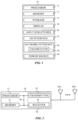
- FIG. 1 is a block diagram of an electronic device 10, according to an embodiment of the present disclosure.
- the electronic device 10 may include, among other things, one or more processors 12 (collectively referred to herein as a single processor for convenience, which may be implemented in any suitable form of processing circuitry), memory 14, nonvolatile storage 16, a display 18, input structures 22, an input/output (I/O) interface 24, a network interface 26, and a power source 29.
- the various functional blocks shown in FIG. 1 may include hardware elements (including circuitry), software elements (including computer code stored on a computer-readable medium) or a combination of both hardware and software elements.
- the processor 12, memory 14, the nonvolatile storage 16, the display 18, the input structures 22, the input/output (I/O) interface 24, the network interface 26, and/or the power source 29 may each be communicatively coupled directly or indirectly (e.g., through or via another component, a communication bus, a network) to one another to transmit and/or receive data between one another.
- FIG. 1 is merely one example of a particular implementation and is intended to illustrate the types of components that may be present in electronic device 10.
- the electronic device 10 may represent a block diagram of any suitable computing device, including a desktop computer, a notebook computer, a portable electronic or handheld electronic device (e.g., a wireless electronic device or smartphone), a tablet, a wearable electronic device, and other similar devices.
- the electronic device 10 may include user equipment or radio frequency communication devices, such as mobile communication devices, smartphones, tablets, wearable devices, and so on.
- the electronic device 10 may include (or may be included in) any suitable communication hub or node, such as a terrestrial communication hub or node, a non-terrestrial communication hub or node, a base station, or a network operator. It should be noted that the processor 12 and other related items in FIG.
- the processor 12 may be generally referred to herein as "data processing circuitry.” Such data processing circuitry may be embodied wholly or in part as software, hardware, or a combination thereof. Furthermore, the processor 12 and other related items in FIG. 1 may be a single contained processing module or may be incorporated wholly or partially within any of the other elements within the electronic device 10.
- the processor 12 may be implemented with any combination of general-purpose microprocessors, microcontrollers, digital signal processors (DSPs), field programmable gate array (FPGAs), programmable logic devices (PLDs), controllers, state machines, gated logic, discrete hardware components, dedicated hardware finite state machines, or any other suitable entities that may perform calculations or other manipulations of information.
- the processors 12 may perform the various functions described herein and below.
- the processor 12 may be operably coupled with a memory 14 and a nonvolatile storage 16 to perform various algorithms.
- Such programs or instructions executed by the processor 12 may be stored in any suitable article of manufacture that includes one or more tangible, computer-readable media.
- the tangible, computer-readable media may include the memory 14 and/or the nonvolatile storage 16, individually or collectively, to store the instructions or routines.
- the memory 14 and the nonvolatile storage 16 may include any suitable articles of manufacture for storing data and executable instructions, such as random-access memory, read-only memory, rewritable flash memory, hard drives, and optical discs.
- programs e.g., an operating system
- encoded on such a computer program product may also include instructions that may be executed by the processor 12 to enable the electronic device 10 to provide various functionalities.
- the display 18 may facilitate users to view images generated on the electronic device 10.
- the display 18 may include a touch screen, which may facilitate user interaction with a user interface of the electronic device 10.
- the display 18 may include one or more liquid crystal displays (LCDs), light-emitting diode (LED) displays, organic light-emitting diode (OLED) displays, active-matrix organic light-emitting diode (AMOLED) displays, or some combination of these and/or other display technologies.
- LCDs liquid crystal displays
- LED light-emitting diode
- OLED organic light-emitting diode
- AMOLED active-matrix organic light-emitting diode
- the input structures 22 of the electronic device 10 may enable a user to interact with the electronic device 10 (e.g., pressing a button to increase or decrease a volume level).
- the I/O interface 24 may enable electronic device 10 to interface with various other electronic devices, as may the network interface 26.
- the network interface 26 may include, for example, one or more interfaces for a personal area network (PAN), such as a BLUETOOTH ® network, for a local area network (LAN) or wireless local area network (WLAN), such as a network employing one of the IEEE 802.11x family of protocols (e.g., WI-FI ® ), and/or for a wide area network (WAN), such as any standards related to the Third Generation Partnership Project (3GPP), including, for example, a 3 rd generation (3G) cellular network, universal mobile telecommunication system (UMTS), 4 th generation (4G) cellular network, long term evolution (LTE ® ) cellular network, long term evolution license assisted access (LTE-LAA) cellular network, 5 th generation (5G) cellular network, and/or New Radio (NR) cellular network, and/or for a non-terrestrial network, such as a satellite communication network.
- PAN personal area network
- LAN local area network
- WLAN wireless local area network
- WAN
- the network interface 26 may include, for example, one or more interfaces for using a Release-15 cellular communication standard of the 5G specifications that include the millimeter wave (mmWave) frequency range (e.g., 24.25-300 gigahertz (GHz)).
- the network interface 26 of the electronic device 10 may allow communication over the aforementioned networks (e.g., 5G, Wi-Fi, LTE-LAA, and so forth).
- the network interface 26 may also include one or more interfaces for, for example, broadband fixed wireless access networks (e.g., WIMAX ® ), mobile broadband Wireless networks (mobile WIMAX ® ), asynchronous digital subscriber lines (e.g., ADSL, VDSL), digital video broadcasting-terrestrial (DVB-T ® ) network and its extension DVB Handheld (DVB-H ® ) network, ultra-wideband (UWB) network, alternating current (AC) power lines, and so forth.
- broadband fixed wireless access networks e.g., WIMAX ®
- mobile broadband Wireless networks e.g., mobile broadband Wireless networks (mobile WIMAX ® )
- asynchronous digital subscriber lines e.g., ADSL, VDSL
- DVD-T ® digital video broadcasting-terrestrial
- DVD-H ® extension DVB Handheld
- UWB ultra-wideband
- AC alternating current
- the network interface 26 may include a transceiver 30.
- the transceiver 30 may support transmission and receipt of various wireless signals via one or more antennas (not shown in FIG. 1 ).
- the power source 29 of the electronic device 10 may include any suitable source of power, such as a rechargeable lithium polymer (Li-poly) battery and/or an alternating current (AC) power converter.
- the electronic device 10 may take the form of a computer, a portable electronic device, a wearable electronic device, or other type of electronic device.
- FIG. 2 is a functional block diagram of the electronic device 10 of FIG. 1 , according to embodiments of the present disclosure.
- the processor 12, the memory 14, the transceiver 30, the transmitter 52, the receiver 54, and/or the antennas 55 may be communicatively coupled directly or indirectly (e.g., through or via another component, a communication bus, a network) to one another to transmit and/or receive data between one another.
- the electronic device 10 may include the transmitter 52 and/or the receiver 54 that respectively enable transmission and reception of data between the electronic device 10 and a remote location via, for example, a network or direct connection associated with the electronic device 10 and an external transceiver (e.g., in the form of a cell, eNB (E-UTRAN Node B or Evolved Node B), or gNB (Next Generation NodeB or gNodeB)), base stations, a non-terrestrial network, a satellite, and the like.
- the transmitter 52 and the receiver 54 may be combined into the transceiver 30.
- the electronic device 10 may also have one or more antennas 55A-55N electrically coupled to the transceiver 30.
- the antennas 55A-55N may be configured in an omnidirectional or directional configuration, in a single-beam, dual-beam, or multi-beam arrangement, and so on. Each antenna 55 may be associated with a one or more beams and various configurations. In some embodiments, multiple antennas of the antennas 55A-55N of an antenna group or module may be communicatively coupled to a respective transceiver 30 and each emit radio frequency signals that may constructively and/or destructively combine to form a beam.
- the electronic device 10 may include (not shown) multiple transmitters, multiple receivers, multiple transceivers, and/or multiple antennas as needed for various communication standards.
- the transmitter 52 may wirelessly transmit packets having different packet types or functions. For example, the transmitter 52 may transmit packets of different types generated by the processor 12.
- the receiver 54 may wirelessly receive packets having different packet types. In some examples, the receiver 54 may detect a type of a packet used and to process the packet accordingly. In some embodiments, the transmitter 52 and the receiver 54 may transmit and receive information via other wired or wireline systems or devices.
- the various components of the electronic device 10 may be coupled together by a bus system 56.
- the bus system 56 may include a data bus, for example, as well as a power bus, a control signal bus, and a status signal bus, in addition to the data bus.
- the components of the electronic device 10 may be coupled together or accept or provide inputs to each other using some other mechanism.
- FIG. 3 is a schematic diagram of the transmitter 52 (e.g., transmit circuitry), according to an embodiment of the present disclosure.
- the transmitter 52 may receive outgoing data 60 in the form of a digital signal to be transmitted via the one or more antennas 55.
- a digital-to-analog converter (DAC) 62 of the transmitter 52 may convert the digital signal to an analog signal, and a modulator 64 may combine the converted analog signal with a carrier signal to generate a radio wave.
- a power amplifier (PA) 66 receives signal the modulated signal from the modulator 64. The power amplifier 66 may amplify the modulated signal to a suitable level to drive transmission of the signal via the one or more antennas 55.
- DAC digital-to-analog converter
- PA power amplifier
- a filter 68 (e.g., filter circuitry and/or software) of the transmitter 52 may then remove undesirable noise from the amplified signal to generate transmitted data 70 to be transmitted via the one or more antennas 55.
- the filter 68 may include any suitable filter or filters to remove the undesirable noise from the amplified signal, such as a bandpass filter, a bandstop filter, a low pass filter, a high pass filter, and/or a decimation filter.
- the transmitter 52 may include any suitable additional components not shown, or may not include certain of the illustrated components, such that the transmitter 52 may transmit the outgoing data 60 via the one or more antennas 55.
- the transmitter 52 may include a mixer and/or a digital up converter.
- the transmitter 52 may not include the filter 68 if the power amplifier 66 outputs the amplified signal in or approximately in a desired frequency range (such that filtering of the amplified signal may be unnecessary).
- FIG. 4 is a schematic diagram of the receiver 54 (e.g., receive circuitry), according to an embodiment of the present disclosure.
- the receiver 54 may receive received data 80 from the one or more antennas 55 in the form of an analog signal.
- a low noise amplifier (LNA) 82 may amplify the received analog signal to a suitable level for the receiver 54 to process.
- a filter 84 e.g., filter circuitry and/or software
- the filter 84 may also remove additional signals received by the one or more antennas 55 which are at frequencies other than the desired signal.
- the filter 84 may include any suitable filter or filters to remove the undesired noise or signals from the received signal, such as a bandpass filter, a bandstop filter, a low pass filter, a high pass filter, and/or a decimation filter.
- a demodulator 86 may remove a radio frequency envelope and/or extract a demodulated signal from the filtered signal for processing.
- An analog-to-digital converter (ADC) 88 may receive the demodulated analog signal and convert the signal to a digital signal of incoming data 90 to be further processed by the electronic device 10.
- the receiver 54 may include any suitable additional components not shown, or may not include certain of the illustrated components, such that the receiver 54 may receive the received data 80 via the one or more antennas 55.
- the receiver 54 may include a mixer and/or a digital down converter.
- FIG. 5 is a diagram 95 illustrating the communicative relationship between user equipment 96, a terrestrial communication node 97, and a non-terrestrial communication node 98.
- the terrestrial communication node 97 may include a base station, such as a base station that provides 5G/New Radio (NR) coverage (e.g., a Next Generation NodeB (gNodeB or gNB) base station) and enables communication to a non-terrestrial network.
- NR Next Generation NodeB
- the user equipment 96 and the terrestrial communication node 97 may include at least some of the components of the electronic device 10 shown in FIGS. 1 and 2 , including the transmitter 52, the receiver 54, and the associated circuitry shown in FIGS. 3 and 4 .
- the user equipment 96 may communicate with the terrestrial communication node 97 to establish a communication link to the non-terrestrial communication node 98.
- the user equipment 96 may send a request (e.g., via the processor 12) to the terrestrial communication node 97 seeking an available uplink frequency channel and/or an available downlink frequency channel to establish communications with the non-terrestrial communication node 98.
- These channels may be within the L frequency band (e.g., a 1.6 gigahertz (GHz) frequency band) and/or the S frequency band (e.g., a 2 GHz frequency band) that may be used for communication with satellites such as the non-terrestrial communication node 98.
- L frequency band e.g., a 1.6 gigahertz (GHz) frequency band
- the S frequency band e.g., a 2 GHz frequency band
- the 1610-1626.5 megahertz (MHz), the 1626.5-1660.5 MHz, and 1668-1675 MHz sub-bands of the L band and the 1980-2010 MHz sub-band of the S band may be used by the user equipment 96 for uplink or transmitting data to the non-terrestrial communication node 98, and the 1518-1559 MHz and the 1613.8-1626.5 MHz sub-bands of the L band and the 2170-2200 MHz and 2483.5-2500 MHz sub-bands of the S band may be used by the user equipment 96 for downlink or receiving data from the non-terrestrial communication node 98.
- a NTN may include a satellite network, a HAPS (high altitude platform system, high altitude platform station, and/or high altitude pseudo-satellite)network, an air-to-ground network, and so on.
- a non-terrestrial communication hub may include any airborne or spaceborne object that has been intentionally placed into orbit, such as a conventional spaceborne orbital satellite having a geostationary or geosynchronous orbit (GEO) at approximately 36,000 kilometers, medium-Earth orbit (MEO) at approximately 7,000 kilometers to 20,000 kilometers, or low-Earth orbit (LEO) at approximately 300 meters to 1,500 kilometers.
- GEO geostationary or geosynchronous orbit
- MEO medium-Earth orbit
- LEO low-Earth orbit
- the non-terrestrial communication hub may include any airborne device or vehicle or atmospheric satellite, such as balloon satellites, manned aircraft (e.g., an airplane, an airship, or any other aircraft), unmanned aircraft systems (UASs), HAPS, and so on. Further, the non-terrestrial communication hub may include a network or constellation of any of the non-terrestrial vehicles, devices, and/or satellites above.
- airborne device or vehicle or atmospheric satellite such as balloon satellites, manned aircraft (e.g., an airplane, an airship, or any other aircraft), unmanned aircraft systems (UASs), HAPS, and so on.
- UASs unmanned aircraft systems
- HAPS unmanned aircraft systems
- the non-terrestrial communication hub may include a network or constellation of any of the non-terrestrial vehicles, devices, and/or satellites above.
- FIG. 6 is a graphical representation of an FCC regulation 100 for an out-of-channel emission mask that may be applied to or implemented on the transmitter 52 of FIG. 3 , according to embodiments of the present disclosure.
- An emission mask or spectrum emission mask is a relative measurement of emission power outside of a target frequency range to transmission power of a signal transmitted in the target frequency range.
- a regulatory or standards entity e.g., the FCC
- the emission mask 104 may thus contain or limit leakage of the transmitted signal in the channel 102 into other frequency ranges, channels, and/or bands, as such leakage may interfere with signals in the other frequency ranges, channels, or bands.
- the horizontal axis 106 in FIG. 6 represents frequency (measured in MHz), and the vertical axis 108 represents power (measured in decibel milliwattss (dBm)/MHz).
- An emission mask may indicate one or more emission thresholds for one or more corresponding ranges of frequencies (e.g., outside of a target frequency range, such as a target band or channel). That is, the emission mask may provide upper limits of signal power (e.g., caused or leaking from the transmitted channel 102) that may be permitted to leak into the corresponding frequency ranges (e.g., nearby frequency channels or bands).
- the emission mask 104 provides one or more emission thresholds for one or more corresponding range of frequencies outside of a target channel, such as the channel 102 centered at 1618.15 MHz.
- the out-of-channel emission mask 104 dictates that signal leakage resulting from the transmitted channel 102 in the frequency range between 1617.65 MHz to 1617.95 MHz cannot exceed a threshold of -18 dBm/MHz.
- any signal leakage in that frequency range may be tolerated below -18 dBm/MHz, but the transmitter 52 equipped with the emission mask 104 conforming to the FCC regulations may not emit a leakage signal in the frequency range above -18 dBm/MHz.
- Signal leakage may be caused by several factors, such as nonlinearities (e.g., a change in the performance due to a change in ambient temperature, real world manufacturing implications, manufacturing defects, non-ideal components) in the electronic device 10.
- the user equipment 96 may include a configuration for the transmitter 52 to contain or limit out-of-band emissions (or, for out-of-channel emission masks, out-of-channel emissions) within one or more threshold powers for one or more frequency ranges.
- the processor 12 may utilize a number of techniques, such as power backoff (e.g., reducing transmission power) and/or frequency filtering (e.g., using the filter 68).
- the user equipment 96 may be configured so as to conform to regulations or standards defined by a regulatory or standards entity, and the regulations/standards may change as the user equipment 96 moves from one geographical region to another.
- the regulations were defined by the FCC.
- the user equipment 96 may be reconfigured to conform to the regulations or standards of the other region (e.g., standards defined by ETSI).
- FIG. 7 is a graphical representation of an ETSI standard 120 for an out-of-band emission mask 124 that may govern the transmitter 52, according to an embodiment of the present disclosure.
- the emission mask 124 may indicate one or more emission thresholds for one or more corresponding range of frequencies outside of a target frequency band 122 between 1610 MHz and 1626.5 MHz.
- the processor 12 may receive or determine the regional standard at which the user equipment 96 is located and configure the transmitter 52 with the out-of-band emission mask 124 illustrated in FIG. 7 (e.g., using the methods 200 or 250 in FIGS. 10 and 11 discussed below) to conform to the regional standard.
- FIG. 8 is a graphical representation of an ETSI standard 130 for an out-of-channel emission mask 134 for a channel with an upper bound at a target frequency that may be applied to or implemented on the transmitter 52, according to an embodiment of the present disclosure.
- the emission mask 134 may indicate one or more emission thresholds for one or more corresponding range of frequencies outside of a target frequency channel 132 with an upper bound at 1618.25 MHz.
- the processor 12 may receive or determine the regional standard at which the user equipment 96 is located and configure the transmitter 52 with the out-of-channel emission mask 134 (e.g., using the methods 200 or 250 in FIGS. 10 and 11 discussed below) to conform to the regional standard.
- FIG. 9 is a graphical representation of an ETSI standard 140 for an out-of-channel emission mask 144 for a channel with a lower bound at the target frequency that may be applied to or implemented on the transmitter 52, according to an embodiment of the present disclosure.
- the emission mask 144 may indicate one or more emission thresholds for one or more corresponding range of frequencies outside of a target frequency channel 142 with a lower bound at 1618.25 MHz.
- the processor 12 may receive or determine the regional standard at which the user equipment 96 is located and configure the transmitter 52 with the out-of-channel emission mask 144 to conform to the regional standard.
- the emission masks 134 and 144 of FIGS. 8 and 9 are channel-specific.
- the ETSI-conforming emission masks 124, 134, and 144 may be applied to channels in the same frequency band, while the user equipment 96 is in the same geographical region (e.g., a region in Europe governed by ETSI). Accordingly, the disclosed embodiments may provide techniques to enable the user equipment 96 to select between different emission masks, even in the same geographical region governed by the same regulatory entity/standard body.
- Conforming to the standards of the geographical region in which the user equipment 96 is located may increase the efficiency of, or even prevent deactivation of, the user equipment 96 in the different geographical regions, as the user equipment may be dynamically set to a more efficient or permissible configuration with respect to non-terrestrial transmission and reception (e.g., when it is determined under which standards the user equipment is to operate).
- the user equipment 96 may determine its location using information received from the terrestrial communication node 97.
- the terrestrial communication node 97 may broadcast system information, via a system information block (SIB), to multiple devices (e.g., the user equipment 96) within range of (e.g., in a cell supported by) the terrestrial communication node 97).
- SIB may include information that enables the user equipment 96 to establish communication with the terrestrial communication node 97, such as one or more network signaling (NS) values that indicate, to the user equipment receiving the SIB, the regulation/standard (e.g., of the FCC, ETSI, MIIT) for which to conform.
- NS network signaling
- the processor 12 of the user equipment 96 may configure the transceiver 30 to conform to the regulation/standard of the region at which the user equipment 96 is located.
- FIG. 10 is a flowchart of a method 200 for configuring the transceiver 30 of the user equipment 96 to conform to regional regulations/standards and communicate with a non-terrestrial network (e.g., including the non-terrestrial communication node 98), according to embodiment of the present disclosure.
- a non-terrestrial network e.g., including the non-terrestrial communication node 98
- Any suitable device e.g., a controller
- the method 200 may be implemented by executing instructions stored in a tangible, non-transitory, computer-readable medium, such as the memory 14 or storage 16, using the processor 12.
- the method 200 may be performed at least in part by one or more software components, such as an operating systems, one or more software applications, and the like, of the user equipment 96, the terrestrial communication node 97, the non-terrestrial network, and the non-terrestrial communication node 98. While the method 200 is described using steps in a specific sequence, it should be understood that the present disclosure contemplates that the described steps may be performed in different sequences than the sequence illustrated, and certain described steps may be skipped or not performed altogether.
- software components such as an operating systems, one or more software applications, and the like
- the user equipment 96 detects the terrestrial communication node 97.
- the user equipment 96 may detect the terrestrial communication node 97 by broadcasting a radio frequency (RF) signal.
- RF radio frequency
- the terrestrial communication node 97 may respond with timing alignment information, among other information.
- the user equipment 96 synchronizes to the terrestrial communication node 97 by aligning its timing with the timing alignment information of the terrestrial communication node 97.
- the terrestrial communication node 97 broadcasts system information with an NS flag or NS value indicating a regional regulation or standard (e.g., an FCC regulation, an ETSI standard, and so on).
- a regional regulation or standard e.g., an FCC regulation, an ETSI standard, and so on.
- the user equipment 96 reads the system information, including the NS value, and thereby determine the regional regulation/standard under which to operate.
- the user equipment 96 configures the transceiver 30 (e.g., the transmitter 52, the receiver 54, or both) based on the regulation/standard indicated by the NS value.
- the user equipment 96 may configure the transceiver 30 by adjusting power of the transmitter 52, adjusting the power of the receiver 54, removing one or more filters from a circuit path of the transceiver 30, adding or removing one or more low noise amplifiers from a circuit path of the transceiver, and so on.
- the user equipment 96 transmits data to or receives data from the non-terrestrial communication node 98 using the configured transceiver 30.
- the non-terrestrial communication node 98 receives data from or transmits data to the user equipment 96.
- the method 200 may enable the user equipment 96 to configure the transceiver 30 to conform to regional regulations/standards and communicate with the non-terrestrial network (e.g., including the non-terrestrial communication node 98).
- FIG. 11 is a flowchart of a method 250 for configuring the transmitter 52 of FIG. 3 (e.g., of the user equipment 96) with an emission mask to conform to regional regulations or standards and communicate with a non-terrestrial network (e.g., including the non-terrestrial communication node 98), according to embodiment of the present disclosure.
- Any suitable device e.g., a controller
- the method 250 may be implemented by executing instructions stored in a tangible, non-transitory, computer-readable medium, such as the memory 14 or storage 16, using the processor 12.
- the method 250 may be performed at least in part by one or more software components, such as an operating systems, one or more software applications, and the like, of the user equipment 96. While the method 250 is described using steps in a specific sequence, it should be understood that the present disclosure contemplates that the described steps may be performed in different sequences than the sequence illustrated, and certain described steps may be skipped or not performed altogether.
- the processor 12 detects the terrestrial communication node 97.
- the processor 12 detects the terrestrial communication node 97 by broadcasting a radio frequency (RF) signal.
- the terrestrial communication node 97 may respond with timing alignment information, among other information.
- the processor 12 synchronizes to the terrestrial communication node 97 by aligning its timing with the timing alignment information of the terrestrial communication node 97.
- the processor 12 receives system information from the terrestrial communication node 97. That is, the terrestrial communication node 97 may broadcast system information to the user equipment 96 with an NS flag or NS value indicating a regional regulation/standard.
- the processor 12 determines whether the NS value indicates ETSI standards. That is, the terrestrial communication node 97 may indicate the regulation/standard that governs the region in which it is located in the NS value.
- the processor 12 configures the transmitter 52 with an emission mask that conforms to default regulations or standards.
- the default regulations/standards may be any set of emission regulations or standards (e.g., defined by ETSI, the FCC, etc.). However, it may be beneficial to set default configuration to a less stringent set of regulations or standards, such as the FCC regulations (as the FCC regulations may be less stringent than the ETSI standards). Therefore, the default configuration may include the emission mask 104 in FIG. 6 .
- the processor 12 configures the transmitter 52 with an emission mask that conforms to ETSI standards (e.g., the emission masks 124, 134, and 134 of FIGS. 7 , 8 , and 9 respectively).
- the processor 12 transmits data to the non-terrestrial communication node 98 using the transmitter 52, as is seen in process block 264. In this manner, the method 250 may enable the processor 12 to configure the transmitter 52 of FIG.
- the user equipment 96 may configure (e.g., via the processor 12) the transmitter 52, as described in the process blocks 260 and 262, by adjusting power of the transmitter 52, removing one or more filters from a circuit path of the transmitter 52, adding or removing one or more low noise amplifiers from a circuit path of the transmitter 52, and so on.
- the emission masks may be band-specific and/or channel-specific.
- the user equipment 96 may remain in the same region (e.g., a region in Europe governed by ETSI)
- there may be several different regulations or standards schemes e.g., the emission masks 124, 134, and 144 in FIGS. 7 , 8 , and 9 respectively
- the disclosed embodiments may provide techniques to enable the user equipment 96 to select between different emission masks, even in the same geographical region governed by the same regulatory entity/standard body.
- regulations/standards for receivers 54 may vary from region to region.
- ETSI has defined out-of-band and out-of-channel standards for signal reception in the S-band for user equipment (e.g., the user equipment 96). These standards may relate to adjacent channel selectivity (ACS), in-band blocking, and/or other performance or noise characteristics.
- ACS adjacent channel selectivity
- FCC regulatory or standards entities
- FIG. 12 is a graphical representation of an ETSI standard 300 for adjacent channel selectivity (ACS) that may be implemented by the receiver 54, according to an embodiment of the present disclosure.
- ACS may include an ability of the receiver 54 to receive a desired reception signal on its assigned channel (e.g., the channel 302 having a center frequency (f c ) 304) in the presence of an interfering or blocking signal in an adjacent channel 305 having a center frequency 308 at a given frequency offset from the center frequency desired reception signal.
- the center frequency 308 of the adjacent channel 305 may be defined as the sum of the center frequency 304 of channel 302 and the bandwidth (BW) 314 of the channel 302 (or f c + BW).
- ETSI standards pertaining to the ACS may define a threshold power of performance degradation or a noise tolerance level (e.g., noise tolerance 310) that may not be exceeded when the interfering signal is at a specified power level (e.g., power level 312).
- ACS-related ETSI standards may provide that desired reception signal on the channel 302 may be degraded no more than 0.5 dB) (e.g., may tolerate no more than 0.5 dB of noise) when the interfering signal is present in an adjacent channel 305 (e.g., having the center frequency 308 that is the sum of the center frequency 304 of channel 302 and the bandwidth 314 of the channel 302) and has a power level 312 that is 12 dB greater than the threshold power of performance degradation/noise tolerance level 310.
- the threshold power of performance degradation is a reference sensitivity power level ("REFSENS") + 0.5 dB
- the power level 312 of the interfering signal 306 is REFSENS +12.5 dB.
- REFSENS reference sensitivity power level
- any suitable threshold power of performance degradation 310 and/or power level of the interfering signal 306 may be used.
- NF noise figure
- RXBW is the received channel bandwidth 302
- diversity gain is signal-to-noise ratio
- IM impairment margin (e.g., a measure of a capability of the receiver 54 to receive a wanted signal on its assigned channel 302 in the presence of two or more interfering signals which have a specific frequency relationship to the wanted signal).
- REFSENS at a channel bandwidth of 20 MHz for an IM of 2.5 dB is -96.7 dBm
- for an IM of 2.0 dB is -97.2 dBm
- for an IM of 1.5 dB is -97.7 dBm
- IM of 1.0 dB is -98.2 dBm.
- REFSENS The primary purpose of REFSENS is to facilitate determining the degradation a desired reception signal (e.g., the channel 302) when noise is introduced (e.g., when the interfering signal 306 is present). Accordingly, the ETSI standard 300 for ACS may ensure that a sufficient quality signal is received by the receiver 54, even in the presence of noise in an adjacent channel 305.
- FIG. 13 is a graphical representation of an ETSI standard 320 for in-band blocking that may be implemented by the receiver 54, according to an embodiment of the present disclosure.
- In-band blocking may prevent noise (e.g., interfering signals) in the same frequency band as a desired received signal from excessively interfering with the desired received signal.
- ETSI standards specifies a threshold power of performance degradation or a noise tolerance level (e.g., threshold power of performance degradation 322) that may not be exceeded when the interfering signals are in the range of 10 MHz less than a lower edge of an operating band (e.g., BE L - 10 MHz) of the received signal and 10 MHz greater than an upper edge of the operating band (e.g., BEu+10 MHz).
- ETSI defines the interfering signals at a fixed offset frequency316 of 5 MHz offset (e.g., an offset frequency) from a center frequency 304 (e.g., f c ) of the channel 302 of the received signal (e.g., f c + 5 MHz, f c - 5 MHz).
- the interfering signals may have frequencies in a same frequency band as the received signal.
- the ETSI standard 320 for in-band blocking may ensure that a sufficient quality signal is received by the receiver 54, even in the presence of noise in the same frequency band (e.g., from 2473.5 MHz to 2510 MHz) as the signal.
- the offset frequency 316 will remain 5 MHz from the center frequency 304, regardless of the bandwidth 314 of the channel 302. As a result, this may limit the ability of the user equipment 96 to receive on channels having bandwidths greater than 5 MHz, and by extension limit the throughput of the channel 302. This will be addressed in greater depth in the discussion of narrowband blocking receiver configurations in FIGS. 15 , 17 , and 20 .
- the processor 12 may configure the receiver 54 to meet blocking regulations or standards, such as the ACS and in-band blocking regulations or standards, by performing power backoff and/or filtering techniques.
- complying with the blocking regulations or standards may result in certain performance trade-offs, such as power or insertion loss, leading to receiver performance or REFSENS degradation (e.g., caused by noise of the interfering signals).
- the user equipment 96 may benefit from configuring the receiver 54 to operate with less stringent blocking regulations or standards. Therefore, it may be advantageous to enable the processor 12 to apply different receiver configurations to meet different regional regulations or standards, depending on where the user equipment 96 is located.
- the processor 12 may configure the receiver 54 with a default configuration adhering to regulations or standards (e.g., FCC regulations) that are less stringent than ETSI standards, and may reconfigure the receiver 54 to meet ETSI standards if the user equipment 96 is located in an area governed by ETSI.
- regulations or standards e.g., FCC regulations
- FIG. 14 is a flowchart of a method 350 for configuring the receiver 54 of FIG. 4 (e.g., of the user equipment 96) to conform to regional regulations/standards governing ACS and/or in-band blocking, and communicate with a non-terrestrial network (e.g., including the non-terrestrial communication node 98), according to an embodiment of the present disclosure.
- Any suitable device e.g., a controller
- the method 350 may be implemented by executing instructions stored in a tangible, non-transitory, computer-readable medium, such as the memory 14 or storage 16, using the processor 12.
- the method 350 may be performed at least in part by one or more software components, such as an operating systems, one or more software applications, and the like, of the user equipment 96. While the method 350 is described using steps in a specific sequence, it should be understood that the present disclosure contemplates that the described steps may be performed in different sequences than the sequence illustrated, and certain described steps may be skipped or not performed altogether.
- the processor 12 may perform process blocks 352, 354, and 356 similarly as process blocks 252, 254, and 256 of method 250 in FIG. 11 .
- the processor 12 determines whether the NS value indicates ETSI standards. That is, the terrestrial communication node 97 may indicate the regulation/standard that governs the region in which it is located in the NS value. If the NS value indicates that ETSI standards do not govern, in process block 360, the processor 12 configures the receiver 54 to conform to default regulations/standards (e.g., FCC regulations). The default regulations/standards may be less stringent than other regulations/standards for which the processor 12 may conform the receiver 54 (e.g., ETSI standards).
- the default regulations/standards may be less stringent than other regulations/standards for which the processor 12 may conform the receiver 54 (e.g., ETSI standards).
- the processor 12 may not configure the receiver 54 at all, as the default, less stringent regulations/standards may not apply to ACS or in-band blocking. If the NS value indicates that ETSI standards govern the region at that the user equipment 96 is located, then, in process block 362, the processor 12 configures the receiver 54 to conform to the ETSI blocking standards. That is, the processor 12 may configured the receiver 54 to conform to the ACS and in-band blocking standards discussed in FIG. 12 and FIG. 13 . In process block 364, after the receiver 54 is configured to conform to the appropriate regulation/standard, the processor 12 receives data from the non-terrestrial communication node 98 using the configured receiver 54. In this manner, the method 350 may enable the processor 12 to configure the receiver 54 of FIG.
- the processor 12 may configure the receiver 54, as described in the process blocks 360 and 362, by adjusting the power of the receiver 54, removing one or more filters from a circuit path of the receiver 54, adding or removing one or more low noise amplifiers from a circuit path of the receiver 54, and so on.
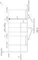
- FIG. 15 is a graphical representation of a narrowband blocking scheme 400 using channel-bandwidth-dependent scaling that may be implemented by the receiver 54, according to an embodiment of the present disclosure.
- Narrowband blocking may prevent noise (e.g., interfering signals) in a narrow frequency band from excessively interfering with a desired received signal.
- the narrowband blocking scheme 400 may be applied to reception in non-terrestrial frequency bands-particularly to signal reception in the S band, though it should be understood that the narrowband blocking scheme 400 may be applied to any suitable frequency range.
- the receiver 54 of the user equipment 96 may be configured by the processor 12 to have less than or equal to a threshold power of performance degradation 322 when the receiver 54 is receiving a signal on a channel (e.g., 302) having a bandwidth (e.g., 314) and a center frequency (e.g., 304), while an interfering signal (e.g., 306) is present at a frequency (e.g., 402) equal to the bandwidth 314 offset (e.g., an offset frequency) from the center frequency 304. That is, the frequency at which the interfering signal 306 is present may scale or change in proportion with the bandwidth 314 of the channel 302.
- a threshold power of performance degradation 322 when the receiver 54 is receiving a signal on a channel (e.g., 302) having a bandwidth (e.g., 314) and a center frequency (e.g., 304), while an interfering signal (e.g., 306) is present at a frequency (e.g., 402) equal to the bandwidth 3
- the threshold power of performance degradation 322 may be REFSENS + 1 dB (such that a desired reception signal on the channel 302 may be degraded no more than 1 dB or may tolerate no more than 0.5 dB of noise when the interfering signal is present), while the power level for the interfering signal 306 under the narrowband blocking scheme 400 may be -40 dBm.
- any suitable threshold power of performance degradation 322 and/or power level of the interfering signal 306 may be used.
- the narrowband blocking scheme 400 may include two interfering signals 306, such that the scalable offset frequency 316 (e.g., equal to the bandwidth 314) may be added to and subtracted from the center frequency 304 (e.g., resulting in two interfering signals 306 being present, one at the center frequency 304 plus the bandwidth 314, and one at the center frequency 304 minus the bandwidth 314).
- the scalable offset frequency 316 e.g., equal to the bandwidth 314
- the center frequency 304 e.g., resulting in two interfering signals 306 being present, one at the center frequency 304 plus the bandwidth 314, and one at the center frequency 304 minus the bandwidth 314.
- narrowband blocking scheme does not have a scalable offset frequency 316 at which the interfering signal 306 (e.g., the offset frequency is fixed, such as in the in-band blocking ETSI standard 320 of FIG. 13 )
- the user equipment 96 may be limited in its ability to adjust the bandwidth 314 of the channel 302. For example, if a narrowband blocking scheme is implemented with a fixed offset frequency of 5 MHz, and the channel 302 has a 5 MHz bandwidth, the distance between the edges of the channel 302 and the interfering signal 306 may be 2.5 MHz.
- the offset frequency may not increase proportionately with the increased bandwidth of the channel 302 because it is fixed at 5 MHz.
- the bandwidth 314 of the channel 302 were to increase from 5 MHz to 7.5 MHz, the distance between the edges of the channel 302 and the interfering signal 306 would be 1.25 MHz.
- the decreased distance between the channel 302 and the interfering signal 306 may result in greater interference with the channel 302 from the interfering signal 306.
- this fixed offset frequency scheme may preclude the use of any channel 302 with a bandwidth 314 of 10 MHz or greater, as the channel 302 and the interfering signal 306 may be placed within the channel 302 itself.
- the channel-bandwidth-dependent narrowband blocking scheme 400 may address this issue by setting the offset frequency 316 of the interfering signal 306 from the center frequency 304 equal to the channel bandwidth of the channel 302. For example, if the bandwidth 314 of the channel 302 were to increase to 7.5 MHz, then the frequency 316 that the interfering signal 306 is offset from the center frequency 304 may increase to ⁇ 7.5 MHz. As can be seen in FIG. 15 , the channel 302 has a bandwidth of 10 MHz, and thus the frequency 316 that the interfering signal 306 is offset from the center frequency 304 may be ⁇ 10MHz.
- the channel-bandwidth-dependent scaling scheme 400 may enable the channel 302 to have a greater bandwidth (and, as a result, throughput), while preventing interference from the interfering signal 306. Moreover, the channel-bandwidth-dependent scaling scheme 400 may be particularly useful for non-terrestrial communication networks, which may take advantage of channel bandwidths of 10 MHz or greater.
- FIG. 16 is a flowchart of a method 450 for configuring the receiver 54 with a narrowband blocking scheme with channel-bandwidth-dependent scaling (e.g., the channel-bandwidth-dependent narrowband blocking scheme 400 of FIG. 15 ), according to an embodiment of the present disclosure.
- Any suitable device e.g., a controller
- the method 450 may be implemented by executing instructions stored in a tangible, non-transitory, computer-readable medium, such as the memory 14 or storage 16, using the processor 12.
- the method 450 may be performed at least in part by one or more software components, such as an operating systems, one or more software applications, and the like, of the user equipment 96, the terrestrial communication node 97, the non-terrestrial network, and the non-terrestrial communication node 98. While the method 450 is described using steps in a specific sequence, it should be understood that the present disclosure contemplates that the described steps may be performed in different sequences than the sequence illustrated, and certain described steps may be skipped or not performed altogether.
- one or more software components such as an operating systems, one or more software applications, and the like
- the processor 12 may perform process blocks 452, 454, and 456 similarly to process blocks 252, 254, and 256 of method 250 in FIG. 11 .
- the processor 12 configures the receiver 54 based on the presence of an interfering signal (e.g., the interfering signal 306) at a frequency a channel bandwidth (e.g., the channel bandwidth 314) away from a channel center frequency (e.g., center frequency 304), as discussed in FIG. 15 .
- the processor 12 may configure the receiver 54 to have less than or equal to a threshold power of performance degradation 322 (e.g., REFSENS + 1 dB) when the receiver 54 is receiving a signal on a channel 302 having a bandwidth 314 and a center frequency 304, while an interfering signal 306 having a power level (e.g., -40 dBm) is present at a frequency 316 offset equal to the bandwidth 314 from the center frequency 304.
- the processor 12 may configure the receiver 54, as described in the process block 458, by adjusting the power of the receiver 54, removing one or more filters from a circuit path of the receiver 54, adding or removing one or more low noise amplifiers from a circuit path of the receiver 54, and so on.
- the processor 12 receives data from a non-terrestrial communication node (e.g., the non-terrestrial communication node 98) using the configured receiver 54.
- the method 450 may enable the processor 12 to configure the receiver 54 of FIG. 4 (e.g., of the user equipment 96) to implement the narrowband blocking scheme 400 with channel-bandwidth-dependent scaling, thus enabling greater channel bandwidths and/or greater throughput.
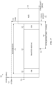
- FIG. 17 is a graphical representation of a narrowband blocking scheme 500 based on the 4G/LTE narrowband blocking specification that may be implemented by the receiver 54, according to an embodiment of the present disclosure. Similar to narrowband blocking scheme 400 with channel-bandwidth-dependent scaling of FIG. 15 , the narrowband blocking scheme 500 implements a scalable frequency 504 of an interfering signal 508 offset (e.g., an offset frequency) from a center frequency 304 of a channel 302 of a desired reception signal (e.g., a wanted signal).
- an interfering signal 508 offset e.g., an offset frequency
- the offset frequency 504 (or unwanted frequency (f uw )) may include half the channel bandwidth 512 and a fixed offset frequency 506 (e.g., 200 kilohertz (kHz)).
- the subcarrier spacing may be associated with a channel 510 of the interfering signal 508, the channel 302 of the desired reception signal, and/or the 4G/LTE standard.
- the channel 302 may also include guard bands 502, which may serve as a buffer or "guard" the received signal and/or its channel 302 from the interfering signal 508.
- the threshold power of performance degradation 516 may depend on the channel bandwidth 512, according to the 3GPP specification.
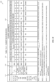
- FIG. 18 is a table 530 illustrating the threshold power of performance degradation 516 for different channel bandwidths 534.
- the threshold power of performance degradation 516 is 16 dB for a channel bandwidth 512 of 5 MHz or 20 MHz, 13 dB for 10 MHz, 14 dB for 15 MHz, and so on.
- the power level 514 e.g., P uw (CW)
- the interfering signal 508 under the narrowband blocking scheme 500 may be -55 dBm.
- the narrowband blocking scheme 500 may include one interfering signal 508 disposed the channel bandwidth 512 away from the center frequency 304.
- the narrowband blocking scheme 500 may include two interfering signals 508, such that the offset frequency 504 may be added to and subtracted from the center frequency 304 (e.g., resulting in two interfering signals 508 being present, one at the center frequency 304 plus the channel bandwidth 512, and one at the center frequency 304 minus the channel bandwidth 512).
- the ceiling function of Equation 2 is performed by rounding any resulting decimal inside the ceiling function up to the nearest integer.
- the offset frequency 504 is 2.7075 MHz.
- the offset frequency 504 is 5.2125 MHz.
- the narrowband blocking scheme 500 based on the 4G/LTE narrowband blocking specification may enable the channel 302 to have a greater bandwidth (and, as a result, throughput), while preventing interference from the interfering signal 508.
- narrowband blocking scheme 500 may be particularly useful for non-terrestrial communication networks, which may take advantage of channel bandwidths of 10 MHz or greater.
- FIG. 19 is a flowchart of a method 550 for configuring the receiver 54 with a narrowband blocking scheme based on the 4G/LTE narrowband blocking specification (e.g., the narrowband blocking scheme 500 of FIG. 17 ), according to an embodiment of the present disclosure.
- Any suitable device e.g., a controller
- the method 550 may be implemented by executing instructions stored in a tangible, non-transitory, computer-readable medium, such as the memory 14 or storage 16, using the processor 12.
- the method 550 may be performed at least in part by one or more software components, such as an operating systems, one or more software applications, and the like, of the user equipment 96, the terrestrial communication node 97, the non-terrestrial network, and the non-terrestrial communication node 98. While the method 550 is described using steps in a specific sequence, it should be understood that the present disclosure contemplates that the described steps may be performed in different sequences than the sequence illustrated, and certain described steps may be skipped or not performed altogether.
- one or more software components such as an operating systems, one or more software applications, and the like
- the processor 12 may perform process blocks 552, 554, and 556 similarly to process blocks 252, 254, and 256 of method 250 in FIG. 11 .
- the user equipment 96 configures the receiver 54 based on the presence of an interfering signal (e.g., interfering signal 508) at a frequency 504 offset (e.g., the unwanted or offset frequency) from the center frequency 304.
- the offset frequency 504 may be based on a channel bandwidth (e.g., the bandwidth 512 of channel 302), a subcarrier spacing associated with the interfering signal 508, and a fixed offset frequency 506.
- the offset frequency 504 may be defined as a first sum of half the subcarrier spacing value and a product of the subcarrier spacing value and a ceiling (e.g., as provided by a ceiling function) of a quotient of a second sum of half the channel bandwidth 512 and the fixed offset frequency 506 (e.g., f offset_fix ) divided by the subcarrier spacing value, as illustrated by Equation 2 above.
- the threshold power of performance degradation 516 may depend on the channel bandwidth 512, according to the 3GPP specification and/or as illustrated in the table 530 of FIG. 18 .
- the power level 514 for the interfering signal 508 under the narrowband blocking scheme 500 may be -55 dBm.
- the processor 12 may configure the receiver 54, as described in the process block 558, by adjusting the power of the receiver 54, removing one or more filters from a circuit path of the receiver 54, adding or removing one or more low noise amplifiers from a circuit path of the receiver 54, and so on.
- the processor 12 receives data from a non-terrestrial communication node (e.g., non-terrestrial communication node 98) using the configured receiver 54.
- the method 550 may enable the processor 12 to configure the receiver 54 of FIG. 4 (e.g., of the user equipment 96) to implement the narrowband blocking scheme 500 based on the 4G/LTE narrowband blocking specification, thus enabling greater channel bandwidths and/or greater throughput.
- FIG. 20 is a graphical representation of a narrowband blocking scheme 600 based on the 5G/New Radio (NR) narrowband blocking specification that may be implemented by the receiver 54, according to an embodiment of the present disclosure.
- NR New Radio
- a desired signal e.g., a wanted signal
- guard bands 502 e.g., guard bands 502
- an interfering signal e.g., interfering signal 604
- narrowband blocking scheme 500 based on the 4G/LTE narrowband blocking specification of FIG.
- the interfering signal 604 may have a frequency 602 (e.g., an unwanted or offset frequency (f uw )) offset from the center frequency 304 of the channel 302.
- a frequency 602 e.g., an unwanted or offset frequency (f uw )
- the offset frequency 602 may be based on the channel bandwidth 512 of the channel 302, a subcarrier spacing value, and a number of resource blocks (NRB).
- the subcarrier spacing and the number of resource blocks or subcarriers may be associated with the channel 510 of the interfering signal 604, the channel 302 of the desired reception signal, and/or the 5G/NR standard.
- the offset frequency 602 may be defined as a sum of half the subcarrier spacing value and a first product of the subcarrier spacing value and a floor (e.g., as provided by a floor function) of a quotient of a difference between the channel bandwidth 512 and half of a second product of the number of resource blocks, the subcarrier spacing value, and a constant value (e.g., 12), divided by the subcarrier spacing value, as illustrated by Equation 3 below: BW ⁇ NRB ⁇ SCS ⁇ 12 2 SCS ⁇ SCS + SCS 2
- the threshold power of performance degradation 516 may depend on the channel bandwidth 512, according to the 3GPP specification and/or the table 530 of FIG. 18 .
- the power level 514 for the interfering signal 604 under the narrowband blocking scheme 600 may be -55 dBm.
- the narrowband blocking scheme 600 may include one interfering signal 604 disposed the channel bandwidth 512 away from the center frequency 304.
- the narrowband blocking scheme 600 may include two interfering signals 604, such that the offset frequency 602 may be added to and subtracted from the center frequency 304 (e.g., resulting in two interfering signals 604 being present, one at the center frequency 304 plus the channel bandwidth 512, and one at the center frequency 304 minus the channel bandwidth 512).
- the floor function of Equation 3 is performed by rounding any resulting decimal inside the ceiling function down to the nearest integer.
- the narrowband blocking scheme 600 based on the 5G/NR narrowband blocking specification is 105 kHz greater.
- the narrowband blocking scheme 600 based on the 5G/NR narrowband blocking specification may enable the channel 302 to have a greater bandwidth (and, as a result, throughput), while preventing interference from the interfering signal 604. Moreover, narrowband blocking scheme 600 may be particularly useful for non-terrestrial communication networks, which may take advantage of channel bandwidths of 10 MHz or greater.
- FIG. 21 is a flowchart of a method 650 for configuring the receiver 54 with a narrowband blocking scheme using the 5G/New Radio (NR) narrowband blocking specification (e.g., the narrowband blocking scheme 600 of FIG. 20 ), according to an embodiment of the present disclosure.
- Any suitable device e.g., a controller
- the method 650 may be implemented by executing instructions stored in a tangible, non-transitory, computer-readable medium, such as the memory 14 or storage 16, using the processor 12.
- the method 650 may be performed at least in part by one or more software components, such as an operating systems, one or more software applications, and the like, of the user equipment 96, the terrestrial communication node 97, the non-terrestrial network, and the non-terrestrial communication node 98. While the method 650 is described using steps in a specific sequence, it should be understood that the present disclosure contemplates that the described steps may be performed in different sequences than the sequence illustrated, and certain described steps may be skipped or not performed altogether.
- one or more software components such as an operating systems, one or more software applications, and the like
- the processor 12 may perform process blocks 652, 654, and 656 similarly to process blocks 252, 254, and 256 of method 250 in FIG. 11 .
- the processor 12 may configure the receiver 54 based on the presence of an interfering signal (e.g., the interfering signal 604) at a frequency 602 (e.g., the unwanted frequency) from a center channel frequency (e.g., center frequency 304 of channel 302).
- the offset frequency 602 may be based on a channel bandwidth (e.g., the bandwidth 512 of channel 302), a subcarrier spacing and a number of resource blocks associated with the interfering signal 604.
- the offset frequency 602 may be defined as a sum of half the subcarrier spacing value and a first product of the subcarrier spacing value and a floor (e.g., as provided by a floor function) of a quotient of a difference between the channel bandwidth 512 and half of a second product of the number of resource blocks, the subcarrier spacing value, and a constant value (e.g., 12), divided by the subcarrier spacing value, as illustrated by Equation 3 above.
- the threshold power of performance degradation 516 may depend on the channel bandwidth 512, according to the 3GPP specification and/or as illustrated in the table 530 of FIG. 18 .
- the power level 514 for the interfering signal 604 under the narrowband blocking scheme 500 may be -55 dBm.
- the processor 12 may configure the receiver 54, as described in the process block 658, by adjusting the power of the receiver 54, removing one or more filters from a circuit path of the receiver 54, adding or removing one or more low noise amplifiers from a circuit path of the receiver 54, and so on.
- the processor 12 receives data from a non-terrestrial communication node (e.g., non-terrestrial communication node 98) using the configured receiver 54.
- the method 650 may enable the processor 12 to configure the receiver 54 of FIG. 4 (e.g., of the user equipment 96) to implement the narrowband blocking scheme 600 based on the 5G/NR narrowband blocking specification, thus enabling greater channel bandwidths and/or greater throughput.
- the various standards e.g., 300, 320, 400
- schemes e.g., 500, 600
- the ETSI standard 320 ensures that a noise level of a received signal on the channel 302 (e.g., having a bandwidth 314 of 5 MHz) does not exceed a threshold 322 (e.g., of 1 decibel (dB)) when there are interfering signals present at 5 MHz less than the center frequency 304 and at 5 MHz greater than the center frequency 304.
- a threshold 322 e.g., of 1 decibel (dB)
- the threshold 322 may be determined based on how far (e.g., in frequency) the interfering signal is offset (e.g., an offset frequency) from the channel 302, as the closer the interfering signal is to the channel 302 (e.g., the smaller the offset frequency 316), the greater the effect of interference from the interfering signal on the channel 302. That is, the threshold 322 varies inversely with the frequency 316 that the interfering signal is offset from the received signal. Moreover, because the offset frequency 316 may vary directly with the channel bandwidth 314, the threshold 322 may also vary directly with the channel bandwidth 314.
- the threshold 322 may be relaxed (e.g., increased) due to the greater effect of interference by the interfering signal. In embodiments where the interfering signal is farther in frequency from the received signal/channel 302, the threshold 322 may be decreased due to the lesser effect of interference by the interfering signal.
- FIG. 22 is a graphical representation of an inverse relationship 700 between a frequency 706 at which an interfering signal 704 is offset (e.g., an offset frequency) from a center frequency 702 of a channel of a received signal, according to embodiments of the present disclosure. For example, when compared to the ETSI standard 320 of FIG.
- the threshold may increase (e.g., be greater than 1 dB) due to the interfering signal being closer to the received signal.
- the threshold may decrease (e.g., be less than 1 dB) due to the interfering signal being closer to the received signal.
- the threshold in FIG. 22 is denoted as REFSENS + ⁇ s, where ⁇ s may indicate a "signal relaxation" (e.g., in dB) that modifies (e.g., positively or negatively) the threshold noise level of a received signal, and where REFSENS serves as a base reference value.
- ⁇ s may inversely vary with respect to how far (e.g., shown as 'd' or the offset frequency ("f_offset”)) the interfering signal is offset from the desired signal and/or a channel of the desired signal.
- ⁇ s may be any suitable value (e.g., between 0 and 100 dB, 0 and 50 dB, 0 and 20 dB, and so on).
- the ⁇ s may be approximately 10 dB to 15 dB (e.g., such that the threshold noise level of the received signal is approximately REFSENS + 10 dB to REFSENS + 15 dB).
- the ⁇ s may be near or approximately 0 dB (e.g., such that the threshold noise level of the received signal is approximately or approaches REFSENS).
- the offset frequency of an interfering signal from a center frequency of a channel having a received signal is 10 MHz.
- the narrowband blocking scheme 500 based on the 4G/LTE narrowband blocking specification of FIG. 17 , the offset frequency is 5.2125 MHz.
- the narrowband blocking scheme using the 5G/NR narrowband blocking specification of FIG. 20 provides an offset frequency of 5.3175 MHz for the same channel bandwidth.
- the threshold noise level of the received signal may be the least for the channel-bandwidth-dependent narrowband blocking scheme 400 of FIG. 15 (e.g., the ⁇ s will be the least), and may be the largest for the 5G/ NR narrowband blocking specification of FIG. 20 (e.g., ⁇ s will be the greatest), with the threshold noise level of the narrowband blocking scheme 500 based on the 4G/LTE narrowband blocking specification of FIG. 17 being between the two (e.g., ⁇ s will be between the two ⁇ s's).
- the present disclosure provides techniques for scaling the noise tolerance of a received signal based on a frequency that an interfering signal is offset from the received signal.
- personally identifiable information should follow privacy policies and practices that are generally recognized as meeting or exceeding industry or governmental requirements for maintaining the privacy of users.
- personally identifiable information data should be managed and handled so as to minimize risks of unintentional or unauthorized access or use, and the nature of authorized use should be clearly indicated to users.
Landscapes
- Engineering & Computer Science (AREA)
- Signal Processing (AREA)
- Computer Networks & Wireless Communication (AREA)
- Physics & Mathematics (AREA)
- Astronomy & Astrophysics (AREA)
- General Physics & Mathematics (AREA)
- Aviation & Aerospace Engineering (AREA)
- Mobile Radio Communication Systems (AREA)
- Radio Relay Systems (AREA)
Applications Claiming Priority (5)
| Application Number | Priority Date | Filing Date | Title |
|---|---|---|---|
| US202163178838P | 2021-04-23 | 2021-04-23 | |
| US17/716,852 US12231222B2 (en) | 2021-04-23 | 2022-04-08 | Methods for conforming non-terrestrial network communication to terrestrial standards and regulations |
| US17/716,824 US12219500B2 (en) | 2021-04-23 | 2022-04-08 | Methods for conforming non-terrestrial network communication to terrestrial standards and regulations |
| US17/716,841 US12088401B2 (en) | 2021-04-23 | 2022-04-08 | Methods for conforming non-terrestrial network communication to terrestrial standards and regulations |
| EP22169147.0A EP4080786A1 (de) | 2021-04-23 | 2022-04-21 | Verfahren zur anpassung von nicht-terrestrischer netzwerkkommunikation an terrestrische normen und vorschriften |
Related Parent Applications (1)
| Application Number | Title | Priority Date | Filing Date |
|---|---|---|---|
| EP22169147.0A Division EP4080786A1 (de) | 2021-04-23 | 2022-04-21 | Verfahren zur anpassung von nicht-terrestrischer netzwerkkommunikation an terrestrische normen und vorschriften |
Publications (2)
| Publication Number | Publication Date |
|---|---|
| EP4468625A2 true EP4468625A2 (de) | 2024-11-27 |
| EP4468625A3 EP4468625A3 (de) | 2025-02-12 |
Family
ID=81346081
Family Applications (2)
| Application Number | Title | Priority Date | Filing Date |
|---|---|---|---|
| EP24205593.7A Pending EP4468625A3 (de) | 2021-04-23 | 2022-04-21 | Verfahren zur anpassung einer nichtterrestrischen netzwerkkommunikation an terrestrische standards und regeln |
| EP22169147.0A Pending EP4080786A1 (de) | 2021-04-23 | 2022-04-21 | Verfahren zur anpassung von nicht-terrestrischer netzwerkkommunikation an terrestrische normen und vorschriften |
Family Applications After (1)
| Application Number | Title | Priority Date | Filing Date |
|---|---|---|---|
| EP22169147.0A Pending EP4080786A1 (de) | 2021-04-23 | 2022-04-21 | Verfahren zur anpassung von nicht-terrestrischer netzwerkkommunikation an terrestrische normen und vorschriften |
Country Status (3)
| Country | Link |
|---|---|
| EP (2) | EP4468625A3 (de) |
| KR (4) | KR102667679B1 (de) |
| CN (3) | CN121037872A (de) |
Families Citing this family (1)
| Publication number | Priority date | Publication date | Assignee | Title |
|---|---|---|---|---|
| WO2025214148A1 (en) * | 2024-04-12 | 2025-10-16 | Telefonaktiebolaget Lm Ericsson (Publ) | Terminal device, network device and methods therein for facilitating orthogonal cover code based transmission |
Family Cites Families (8)
| Publication number | Priority date | Publication date | Assignee | Title |
|---|---|---|---|---|
| US5949796A (en) * | 1996-06-19 | 1999-09-07 | Kumar; Derek D. | In-band on-channel digital broadcasting method and system |
| WO2008123148A1 (ja) * | 2007-03-30 | 2008-10-16 | Ntt Docomo, Inc. | 移動通信システム、基地局装置、ユーザ装置及び方法 |
| US10321450B2 (en) * | 2014-12-09 | 2019-06-11 | Myriota Pty Ltd | Multicarrier communications system |
| US9900856B2 (en) * | 2015-03-20 | 2018-02-20 | Qualcomm Incorporated | Method and apparatus for time or frequency synchronization in non-geosynchronous satellite communication systems |
| KR102429823B1 (ko) * | 2017-09-29 | 2022-08-05 | 프라운호퍼 게젤샤프트 쭈르 푀르데룽 데어 안겐반텐 포르슝 에. 베. | 비-지상 통신들을 위한 시스템 |
| US11050598B2 (en) * | 2017-11-28 | 2021-06-29 | Qualcomm Incorporated | Carrier information signaling in a 5G network |
| WO2020033643A1 (en) * | 2018-08-10 | 2020-02-13 | Intel Corporation | Downlink signal and noise control to test user equipment performance requirements |
| US10848237B1 (en) * | 2019-07-08 | 2020-11-24 | Dish Wireless L.L.C. | Spectrum sharing for a terrestrial-satellite hybrid environment |
-
2022
- 2022-04-21 EP EP24205593.7A patent/EP4468625A3/de active Pending
- 2022-04-21 EP EP22169147.0A patent/EP4080786A1/de active Pending
- 2022-04-22 CN CN202511257280.9A patent/CN121037872A/zh active Pending
- 2022-04-22 KR KR1020220050124A patent/KR102667679B1/ko active Active
- 2022-04-22 CN CN202210431155.5A patent/CN115243282B/zh active Active
- 2022-04-22 CN CN202411410393.3A patent/CN119110323A/zh active Pending
-
2024
- 2024-05-16 KR KR1020240063761A patent/KR102763174B1/ko active Active
- 2024-10-07 KR KR1020240135437A patent/KR102761141B1/ko active Active
-
2025
- 2025-01-31 KR KR1020250012447A patent/KR20250022735A/ko active Pending
Also Published As
| Publication number | Publication date |
|---|---|
| KR102763174B1 (ko) | 2025-02-07 |
| CN115243282B (zh) | 2025-09-12 |
| KR20220146353A (ko) | 2022-11-01 |
| KR102761141B1 (ko) | 2025-02-03 |
| EP4080786A1 (de) | 2022-10-26 |
| KR20240152783A (ko) | 2024-10-22 |
| CN119110323A (zh) | 2024-12-10 |
| KR102667679B1 (ko) | 2024-05-23 |
| CN115243282A (zh) | 2022-10-25 |
| CN121037872A (zh) | 2025-11-28 |
| KR20240078411A (ko) | 2024-06-03 |
| KR20250022735A (ko) | 2025-02-17 |
| EP4468625A3 (de) | 2025-02-12 |
Similar Documents
| Publication | Publication Date | Title |
|---|---|---|
| US20250119848A1 (en) | Methods for conforming non-terrestrial network communication to terrestrial standards and regulations | |
| US11503658B2 (en) | Smart scheduling for intermodulation distortion avoidance on multiple uplink transmissions | |
| US12355708B2 (en) | Systems and methods for supporting irregular bandwidth channels | |
| US9894539B2 (en) | Digital full duplex over single channel solution for small cell backhaul applications | |
| KR102757099B1 (ko) | 비-지상 대역 식별자들을 신호전달하기 위한 시스템 및 방법 | |
| KR102761141B1 (ko) | 비-지상 네트워크 통신을 지상 표준 및 규정에 순응시키기 위한 방법 | |
| US20230354161A1 (en) | Frequency band having variable duplex spacing | |
| US12231222B2 (en) | Methods for conforming non-terrestrial network communication to terrestrial standards and regulations | |
| US12088401B2 (en) | Methods for conforming non-terrestrial network communication to terrestrial standards and regulations | |
| US20240406883A1 (en) | Systems and methods for conforming to indoor/outdoor regulations in unlicensed bands | |
| US12513509B2 (en) | Systems and methods for supporting evolving band regulations | |
| CN111555788A (zh) | 蜂窝和公共安全中继器 | |
| US20230093722A1 (en) | Systems and methods for multiple haps base station connection | |
| US12556211B2 (en) | Systems and methods for direct current leakage location signaling | |
| US20240283477A1 (en) | Systems and methods for direct current leakage location signaling | |
| US20240097710A1 (en) | Radio access technology (rat) spectrum translator | |
| WO2023211623A1 (en) | Frequency band having variable duplex spacing | |
| CN116939582A (zh) | 用于支持演进带监管的系统和方法 |
Legal Events
| Date | Code | Title | Description |
|---|---|---|---|
| PUAI | Public reference made under article 153(3) epc to a published international application that has entered the european phase |
Free format text: ORIGINAL CODE: 0009012 |
|
| STAA | Information on the status of an ep patent application or granted ep patent |
Free format text: STATUS: REQUEST FOR EXAMINATION WAS MADE |
|
| 17P | Request for examination filed |
Effective date: 20241009 |
|
| AC | Divisional application: reference to earlier application |
Ref document number: 4080786 Country of ref document: EP Kind code of ref document: P |
|
| AK | Designated contracting states |
Kind code of ref document: A2 Designated state(s): AL AT BE BG CH CY CZ DE DK EE ES FI FR GB GR HR HU IE IS IT LI LT LU LV MC MK MT NL NO PL PT RO RS SE SI SK SM TR |
|
| PUAL | Search report despatched |
Free format text: ORIGINAL CODE: 0009013 |
|
| AK | Designated contracting states |
Kind code of ref document: A3 Designated state(s): AL AT BE BG CH CY CZ DE DK EE ES FI FR GB GR HR HU IE IS IT LI LT LU LV MC MK MT NL NO PL PT RO RS SE SI SK SM TR |
|
| RIC1 | Information provided on ipc code assigned before grant |
Ipc: H04W 84/06 20090101ALI20250109BHEP Ipc: H04W 56/00 20090101ALI20250109BHEP Ipc: H04B 7/185 20060101AFI20250109BHEP |