EP4468591A1 - Motor control device - Google Patents
Motor control device Download PDFInfo
- Publication number
- EP4468591A1 EP4468591A1 EP22921003.4A EP22921003A EP4468591A1 EP 4468591 A1 EP4468591 A1 EP 4468591A1 EP 22921003 A EP22921003 A EP 22921003A EP 4468591 A1 EP4468591 A1 EP 4468591A1
- Authority
- EP
- European Patent Office
- Prior art keywords
- torque
- command value
- steering
- unit
- angle
- Prior art date
- Legal status (The legal status is an assumption and is not a legal conclusion. Google has not performed a legal analysis and makes no representation as to the accuracy of the status listed.)
- Pending
Links
- 238000012937 correction Methods 0.000 claims abstract description 14
- 238000001514 detection method Methods 0.000 claims description 15
- 230000014509 gene expression Effects 0.000 description 66
- 238000012545 processing Methods 0.000 description 57
- 238000010586 diagram Methods 0.000 description 39
- 230000009467 reduction Effects 0.000 description 39
- 230000006870 function Effects 0.000 description 25
- 239000011159 matrix material Substances 0.000 description 20
- 238000012546 transfer Methods 0.000 description 18
- 230000033001 locomotion Effects 0.000 description 14
- 238000013016 damping Methods 0.000 description 11
- 230000007246 mechanism Effects 0.000 description 11
- 238000011144 upstream manufacturing Methods 0.000 description 9
- 239000003638 chemical reducing agent Substances 0.000 description 8
- 230000001629 suppression Effects 0.000 description 8
- 230000001133 acceleration Effects 0.000 description 5
- 230000000694 effects Effects 0.000 description 5
- 230000003247 decreasing effect Effects 0.000 description 4
- 230000010354 integration Effects 0.000 description 3
- 238000006243 chemical reaction Methods 0.000 description 2
- 238000002474 experimental method Methods 0.000 description 2
- 101000582320 Homo sapiens Neurogenic differentiation factor 6 Proteins 0.000 description 1
- 102100030589 Neurogenic differentiation factor 6 Human genes 0.000 description 1
- 230000003466 anti-cipated effect Effects 0.000 description 1
- 230000005540 biological transmission Effects 0.000 description 1
- 230000004069 differentiation Effects 0.000 description 1
- 238000006073 displacement reaction Methods 0.000 description 1
- 238000001914 filtration Methods 0.000 description 1
- 230000004048 modification Effects 0.000 description 1
- 238000012986 modification Methods 0.000 description 1
- 230000004044 response Effects 0.000 description 1
- 239000000725 suspension Substances 0.000 description 1
Images






Classifications
-
- B—PERFORMING OPERATIONS; TRANSPORTING
- B62—LAND VEHICLES FOR TRAVELLING OTHERWISE THAN ON RAILS
- B62D—MOTOR VEHICLES; TRAILERS
- B62D5/00—Power-assisted or power-driven steering
- B62D5/04—Power-assisted or power-driven steering electrical, e.g. using an electric servo-motor connected to, or forming part of, the steering gear
- B62D5/0457—Power-assisted or power-driven steering electrical, e.g. using an electric servo-motor connected to, or forming part of, the steering gear characterised by control features of the drive means as such
- B62D5/046—Controlling the motor
- B62D5/0472—Controlling the motor for damping vibrations
-
- B—PERFORMING OPERATIONS; TRANSPORTING
- B62—LAND VEHICLES FOR TRAVELLING OTHERWISE THAN ON RAILS
- B62D—MOTOR VEHICLES; TRAILERS
- B62D5/00—Power-assisted or power-driven steering
- B62D5/04—Power-assisted or power-driven steering electrical, e.g. using an electric servo-motor connected to, or forming part of, the steering gear
- B62D5/0457—Power-assisted or power-driven steering electrical, e.g. using an electric servo-motor connected to, or forming part of, the steering gear characterised by control features of the drive means as such
- B62D5/046—Controlling the motor
-
- B—PERFORMING OPERATIONS; TRANSPORTING
- B62—LAND VEHICLES FOR TRAVELLING OTHERWISE THAN ON RAILS
- B62D—MOTOR VEHICLES; TRAILERS
- B62D6/00—Arrangements for automatically controlling steering depending on driving conditions sensed and responded to, e.g. control circuits
- B62D6/008—Control of feed-back to the steering input member, e.g. simulating road feel in steer-by-wire applications
-
- H—ELECTRICITY
- H02—GENERATION; CONVERSION OR DISTRIBUTION OF ELECTRIC POWER
- H02P—CONTROL OR REGULATION OF ELECTRIC MOTORS, ELECTRIC GENERATORS OR DYNAMO-ELECTRIC CONVERTERS; CONTROLLING TRANSFORMERS, REACTORS OR CHOKE COILS
- H02P21/00—Arrangements or methods for the control of electric machines by vector control, e.g. by control of field orientation
- H02P21/05—Arrangements or methods for the control of electric machines by vector control, e.g. by control of field orientation specially adapted for damping motor oscillations, e.g. for reducing hunting
-
- H—ELECTRICITY
- H02—GENERATION; CONVERSION OR DISTRIBUTION OF ELECTRIC POWER
- H02P—CONTROL OR REGULATION OF ELECTRIC MOTORS, ELECTRIC GENERATORS OR DYNAMO-ELECTRIC CONVERTERS; CONTROLLING TRANSFORMERS, REACTORS OR CHOKE COILS
- H02P21/00—Arrangements or methods for the control of electric machines by vector control, e.g. by control of field orientation
- H02P21/14—Estimation or adaptation of machine parameters, e.g. flux, current or voltage
- H02P21/20—Estimation of torque
-
- H—ELECTRICITY
- H02—GENERATION; CONVERSION OR DISTRIBUTION OF ELECTRIC POWER
- H02P—CONTROL OR REGULATION OF ELECTRIC MOTORS, ELECTRIC GENERATORS OR DYNAMO-ELECTRIC CONVERTERS; CONTROLLING TRANSFORMERS, REACTORS OR CHOKE COILS
- H02P23/00—Arrangements or methods for the control of AC motors characterised by a control method other than vector control
- H02P23/04—Arrangements or methods for the control of AC motors characterised by a control method other than vector control specially adapted for damping motor oscillations, e.g. for reducing hunting
-
- H—ELECTRICITY
- H02—GENERATION; CONVERSION OR DISTRIBUTION OF ELECTRIC POWER
- H02P—CONTROL OR REGULATION OF ELECTRIC MOTORS, ELECTRIC GENERATORS OR DYNAMO-ELECTRIC CONVERTERS; CONTROLLING TRANSFORMERS, REACTORS OR CHOKE COILS
- H02P23/00—Arrangements or methods for the control of AC motors characterised by a control method other than vector control
- H02P23/14—Estimation or adaptation of motor parameters, e.g. rotor time constant, flux, speed, current or voltage
-
- H—ELECTRICITY
- H02—GENERATION; CONVERSION OR DISTRIBUTION OF ELECTRIC POWER
- H02P—CONTROL OR REGULATION OF ELECTRIC MOTORS, ELECTRIC GENERATORS OR DYNAMO-ELECTRIC CONVERTERS; CONTROLLING TRANSFORMERS, REACTORS OR CHOKE COILS
- H02P6/00—Arrangements for controlling synchronous motors or other dynamo-electric motors using electronic commutation dependent on the rotor position; Electronic commutators therefor
- H02P6/10—Arrangements for controlling torque ripple, e.g. providing reduced torque ripple
-
- H—ELECTRICITY
- H02—GENERATION; CONVERSION OR DISTRIBUTION OF ELECTRIC POWER
- H02P—CONTROL OR REGULATION OF ELECTRIC MOTORS, ELECTRIC GENERATORS OR DYNAMO-ELECTRIC CONVERTERS; CONTROLLING TRANSFORMERS, REACTORS OR CHOKE COILS
- H02P2205/00—Indexing scheme relating to controlling arrangements characterised by the control loops
- H02P2205/05—Torque loop, i.e. comparison of the motor torque with a torque reference
Definitions
- This invention relates to a motor control device that controls an electric motor that applies steering force to an output shaft linked to a steering wheel via a torsion bar.
- Patent Document 1 discloses that a disturbance torque, which is a torque other than a motor torque that acts on a motor-driven object, is subtracted from a basic torque command value, and a vibration suppression torque obtained by multiplying steering torque (torsion bar torque) by a predetermined vibration suppression gain is added to the subtraction results, thereby computing a torque command value for an output shaft.
- the basic torque command value includes a feedback torque obtained by performing PD (proportional derivative) computation with respect to deviation between an automatic steering angle command value and a steering angle detection value or a steering angle estimation value.
- vibration is suppressed by setting a vibration suppression gain, a proportional gain used in PD computation, and a differential gain used in PD computation, to respective predetermined values.
- Patent Document 1 Japanese Unexamined Patent Application Publication No. 2018-183046 ( JP 2018-183046 A )
- vibration can be suppressed, but resonant frequency of the system is fixed to mechanical natural frequency (resonant frequency) of a steering wheel, and accordingly the resonant frequency of the system cannot be optionally set.
- An object of this invention is to provide a motor control device that enables the resonant frequency of the system to be optionally set.
- An embodiment of the present invention provides a motor control device that controls an electric motor that applies steering force to an output shaft linked to a steering wheel via a torsion bar, the motor control device including a steering torque detection unit that detects a steering torque applied to the steering wheel, and a motor torque command value setting unit that sets a motor torque command value that is a target value of motor torque of the electric motor, in which the motor torque command value setting unit includes a basic torque command value setting unit that sets a basic torque command value, a correction unit that corrects the basic torque command value set by the basic torque command value setting unit, using a resonance control torque, and a motor torque command value computation unit that computes the motor torque command value based on the basic torque command value following correction by the correction unit, and the resonance control torque is set using a first torque obtained by multiplying a differential value of the steering torque by a predetermined first gain, and a second torque obtained by multiplying the steering torque by a predetermined second gain.
- the resonant frequency of the system can be optionally set.
- An embodiment of the present invention provides a motor control device that controls an electric motor that applies steering force to an output shaft linked to a steering wheel via a torsion bar, the motor control device including a steering torque detection unit that detects a steering torque applied to the steering wheel, and a motor torque command value setting unit that sets a motor torque command value that is a target value of motor torque of the electric motor, in which the motor torque command value setting unit includes a basic torque command value setting unit that sets a basic torque command value, a correction unit that corrects the basic torque command value set by the basic torque command value setting unit, using a resonance control torque, and a motor torque command value computation unit that computes the motor torque command value based on the basic torque command value following correction by the correction unit, and the resonance control torque is set using a first torque obtained by multiplying a differential value of the steering torque by a predetermined first gain, and a second torque obtained by multiplying the steering torque by a predetermined second gain.
- the resonant frequency of the system can be optionally set.
- An embodiment of the present invention further includes a rotational angle detection unit that detects a rotational angle of the electric motor, in which the basic torque command value setting unit includes an angle deviation computation unit that computes a difference between a rotational angle command value that is a target value of a rotational angle of the output shaft and a rotational angle of the output shaft computed from the rotational angle detected by the rotational angle detection unit, and a basic torque command value computation unit that computes the basic torque command value by performing predetermined feedback computation with respect to angle deviation computed by the angle deviation computation unit.
- An embodiment of the present invention further includes a rotational angle detection unit that detects a rotational angle of the electric motor, in which the basic torque command value setting unit includes a target torque computation unit that computes a target torque based on a rotational angle command value that is a target value of a rotational angle of the output shaft, a feedback torque computation unit that computes a feedback torque based on the rotational angle detected by the rotational angle detection unit, and a basic torque command value computation unit that computes the basic torque command value by computing a deviation between the target torque and the feedback torque, and a gain used in the computation of the target torque and a gain used in the computation of the feedback torque are different from each other.
- the basic torque command value setting unit includes a target torque computation unit that computes a target torque based on a rotational angle command value that is a target value of a rotational angle of the output shaft, a feedback torque computation unit that computes a feedback torque based on the rotational angle detected by the rotational angle detection unit, and a basic torque command value
- An embodiment of the present invention further includes a manual steering command value computation unit that generates a manual steering command value and an integrated angle command value computation unit that computes an integrated angle command value by adding the manual steering command value to an automatic steering angle command value, in which the rotational angle command value is the integrated angle command value.
- An embodiment of the present invention further includes a disturbance torque estimation unit that estimates disturbance torque other than the motor torque of the electric motor acting on the output shaft, based on the motor torque command value or the motor torque generated by the electric motor, and a rotational angle of the output shaft, in which the correction unit is configured to correct the basic torque command value by using the resonance control torque and the disturbance torque.
- a dead band is set for at least one of the steering torque that is an input value for computing the first torque, and the steering torque that is an input value for computing the second torque.
- FIG. 1 is a schematic diagram illustrating a schematic configuration of an electric power steering system to which a motor control device according to a first embodiment of the present invention is applied.
- An electric power steering system 1 includes a steering wheel (handle) 2 that is a steering member for steering a vehicle, a steering operation mechanism 4 that steers steered wheels 3 in conjunction with rotating of the steering wheel 2, and a steering assist mechanism 5 that assists a driver in steering.
- the steering wheel 2 and the steering operation mechanism 4 are mechanically linked via a steering shaft 6 and an intermediate shaft 7.
- the steering shaft 6 includes an input shaft 8 linked to the steering wheel 2 and an output shaft 9 linked to the intermediate shaft 7.
- the input shaft 8 and the output shaft 9 are linked so as to be rotatable relative to each other via a torsion bar 10.
- a torque sensor 12 is disposed near the torsion bar 10.
- the torque sensor 12 detects steering torque (torsion bar torque) T tb applied to the steering wheel 2 based on an amount of relative rotational displacement between the input shaft 8 and the output shaft 9. That is to say, the torque sensor 12 detects the steering torque T tb based on the amount of twisting of the torsion bar 10.
- the steering torque T tb that is detected by the torque sensor 12 is such that, for example, torque for steering in a left direction is detected as a positive value, torque for steering in a right direction is detected as a negative value, and the greater the absolute value thereof is, the greater the magnitude of the steering torque T tb becomes.
- the steering operation mechanism 4 is made up of a rack and pinion mechanism including a pinion shaft 13 and a rack shaft 14 that is a steered shaft.
- the steered wheels 3 are linked to the end portions of the rack shaft 14 via tie rods 15 and knuckle arms (omitted from illustration).
- the pinion shaft 13 is linked to the intermediate shaft 7.
- the pinion shaft 13 is configured to rotate in conjunction with steering by the steering wheel 2.
- a pinion 16 is linked to a distal end of the pinion shaft 13.
- the rack shaft 14 extends linearly along a right-left direction of the vehicle.
- a rack 17 that meshes with the pinion 16 is formed on an intermediate portion of the rack shaft 14 in an axial direction.
- the pinion 16 and the rack 17 convert rotation of the pinion shaft 13 into axial direction movement of the rack shaft 14.
- the steered wheels 3 can be steered by moving the rack shaft 14 in the axial direction.
- the steering assist mechanism 5 includes an electric motor 18 for generating a steering assist force (assist torque), and a speed reducer 19 for amplifying output torque of the electric motor 18 and transmitting the amplified torque to the steering operation mechanism 4.
- the speed reducer 19 is made up of a worm gear mechanism including a worm gear 20 and a worm wheel 21 that meshes with the worm gear 20.
- the speed reducer 19 is housed in a gear housing 22 serving as a transmission mechanism housing.
- reduction ratio (gear ratio) of the speed reducer 19 may be represented by N in some cases.
- the reduction ratio N is defined as a ratio ( ⁇ wg / ⁇ ww ) of a worm gear angle ⁇ wg that is a rotational angle of the worm gear 20 as to a worm wheel angle ⁇ ww that is a rotational angle of the worm wheel 21.
- the worm gear 20 is rotationally driven by the electric motor 18. Also, the worm wheel 21 is linked to the output shaft 9 so as to be integrally rotatable therewith.
- the worm gear 20 When the worm gear 20 is rotationally driven by the electric motor 18, the worm wheel 21 is rotationally driven so that motor torque is applied to the steering shaft 6, and also the steering shaft 6 (output shaft 9) is rotated. The rotation of the steering shaft 6 is then transmitted to the pinion shaft 13 via the intermediate shaft 7. The rotation of the pinion shaft 13 is converted into axial direction movement of the rack shaft 14.
- the steered wheels 3 are thus steered. That is to say, rotationally driving the worm gear 20 by the electric motor 18 enables steering assist by the electric motor 18 and steering of the steered wheels 3.
- the electric motor 18 is provided with a rotational angle sensor 23 for detecting a rotational angle of a rotor of the electric motor 18.
- Torque that is applied to the output shaft 9 includes motor torque from the electric motor 18 and disturbance torque T lc other than the motor torque.
- the disturbance torque T lc other than the motor torque includes steering torque T tb , road load torque (road reaction torque) T rl , friction torque T f , and so forth.
- the steering torque T tb is torque that is applied from the steering wheel 2 side to the output shaft 9, due to force that is applied to the steering wheel 2 by the driver (driver torque), force that is generated by steering inertia, and so forth.
- Road load torque T rl is torque that is applied from the steered wheel 3 side to the output shaft 9 via the rack shaft 14, due to self-aligning torque that is generated by tires, force that is generated by suspension and tire wheel alignment, friction force of the rack and pinion mechanism, and so forth.
- the vehicle is equipped with a CCD (Charge Coupled Device) camera 25 that performs shooting of the road ahead in a direction of travel of the vehicle, a GPS (Global Positioning System) 26 for detecting the position of the own vehicle, a radar 27 for detecting road shape and obstructions, and map information memory 28 that stores map information.
- CCD Charge Coupled Device
- GPS Global Positioning System
- map information memory 28 that stores map information.
- the vehicle is further equipped with three mode switches 31, 32, and 33 for manually switching steering modes.
- the steering modes include a manual steering mode in which steering is performed by manual driving, an automatic steering mode in which steering is performed by automated driving, and a cooperative steering mode in which steering can be performed based on both manual driving and automated driving. Specific definitions of these steering modes will be described later.
- the CCD camera 25, the GPS 26, the radar 27, and the map information memory 28 are connected to a host ECU (ECU: Electronic Control Unit) 201 for performing driver assistance control and automated driving control.
- the host ECU 201 performs surrounding environment recognition, own vehicle position estimation, route planning, and so forth, based on information obtained by the CCD camera 25, the GPS 26, and the radar 27, and also the map information, and determines control target values for steering and drive actuators.
- the host ECU 201 sets an automatic steering command value ⁇ adac for automatic steering.
- automatic steering control is, for example, control for causing the vehicle to travel along a target course.
- the automatic steering command value ⁇ adac is a target value of a steering angle for causing the vehicle to travel automatically along the target course. Processing of setting such an automatic steering command value ⁇ adac is well known, and accordingly detailed description will be omitted here.
- automatic steering control driver assistance control
- LKA lane keeping assist
- the host ECU 201 also generates mode setting signals S1, S2, and S3 in accordance with operations of the mode switches 31, 32, and 33. Specifically, when the first mode switch 31 is turned on by the driver, the host ECU 201 outputs a manual steering setting signal S1 for setting the steering mode to the manual steering mode. When the second mode switch 32 is turned on by the driver, the host ECU 201 outputs an automatic steering mode setting signal S2 for setting the steering mode to the automatic steering mode. When the third mode switch 33 is turned on by the driver, the host ECU 201 outputs a cooperative steering mode setting signal S3 for setting the steering mode to the cooperative steering mode.
- the automatic steering command value ⁇ adac and the mode setting signals S1, S2, and S3 that are set by the host ECU 201 are given to a motor control ECU 202 via an in-vehicle network.
- the steering torque T tb detected by the torque sensor 12 and output signals from the rotational angle sensor 23 are input to the motor control ECU 202.
- the motor control ECU 202 controls the electric motor 18 based on these input signals and information given from the host ECU 201.
- FIG. 2 is a block diagram illustrating an electrical configuration of the motor control ECU 202.
- the motor control ECU 202 includes a microcomputer 50, a drive circuit (inverter circuit) 41 that is controlled by the microcomputer 50 and that supplies electric power to the electric motor 18, and a current detection circuit 42 for detecting a current flowing through the electric motor 18 (hereinafter referred to as "motor current I").
- the microcomputer 50 includes a CPU and memory (such as ROM, RAM, non-volatile memory, and so forth), and functions as a plurality of functional processing units by executing a predetermined program.
- This plurality of functional processing units includes an assist torque command value setting unit 51, a manual steering command value generation unit 52, an integrated angle command value computation unit 53, an angle control unit 54, a torque control unit (current control unit) 55, a first weighting unit 56, a second weighting unit 57, a third weighting unit 58, and an addition unit 59.
- the addition unit 59 in the present embodiment is an example of "motor torque command value computation unit" according to the present invention.
- the assist torque command value setting unit 51 sets an assist torque command value T as that is a target value of the assist torque necessary for manual operations.
- the assist torque command value setting unit 51 sets the assist torque command value T as based on the steering torque T tb detected by the torque sensor 12.
- An example of setting the assist torque command value T as with respect to the steering torque T tb is illustrated in FIG. 3 .
- the assist torque command value T as is set to a positive value when the electric motor 18 should generate a steering assist force for steering in the left direction, and is set to a negative value when the electric motor 18 should generate a steering assist force for steering in the right direction.
- the assist torque command value T as is positive for a positive value of the steering torque T tb , and is negative for a negative value of the steering torque T tb .
- the assist torque command value T as is set such that the greater an absolute value of the steering torque T tb is, the greater an absolute value of the assist torque command value T as becomes.
- the assist torque command value setting unit 51 may set the assist torque command value T as also taking into consideration a vehicle speed detected by a vehicle speed sensor that is omitted from illustration.
- assist torque command value setting unit 51 may compute the assist torque command value T as by multiplying the steering torque T tb by a constant that is set in advance.
- the first weighting unit 56 performs first weighting processing with respect to the assist torque command value T as set by the assist torque command value setting unit 51, in accordance with the mode setting signal that is input. Specifically, when one of the mode setting signals S1, S2, and S3 is input, the first weighting unit 56 first sets a first weight W 1 in accordance with the current steering mode and the mode setting signal that is input. Next, the first weighting unit 56 multiplies the assist torque command value T as by the first weight W 1 . The first weighting unit 56 then gives a multiplication value W 1 ⁇ T as to the addition unit 59 as an assist torque command value T as ' following the first weighting processing.
- the manual steering command value generation unit 52 is provided to, when the driver operates the steering wheel 2, set the steering angle (more precisely, rotational angle ⁇ of the output shaft 9) in accordance with this steering wheel operation, as a manual steering command value ⁇ mdac .
- the manual steering command value generation unit 52 generates the manual steering command value ⁇ mdac using the steering torque T tb detected by the torque sensor 12 and the assist torque command value T as set by the assist torque command value setting unit 51.
- the manual steering command value generation unit 52 will be described later in detail.
- the third weighting unit 58 performs third weighting processing with respect to the manual steering command value ⁇ mdac generated by the manual steering command value generation unit 52, in accordance with the mode setting signal that is input. Specifically, when one of the mode setting signals S1, S2, and S3 is input, the third weighting unit 58 first sets a third weight W 3 in accordance with the current steering mode and the mode setting signal that is input. Next, the third weighting unit 58 multiplies the manual steering command value ⁇ mdac by the third weight W 3 . The third weighting unit 58 then gives a multiplication value W 3 ⁇ mdac to the integrated angle command value computation unit 53, as a manual steering command value ⁇ mdac ' following the third weighting processing.
- the integrated angle command value computation unit 53 computes an integrated angle command value ⁇ sint by adding the manual steering command value ⁇ mdac ' following the third weighting processing to the automatic steering command value ⁇ adac set by the host ECU 201.
- the angle control unit 54 computes an integrated motor torque command value T mint in accordance with the integrated angle command value ⁇ sint , based on the integrated angle command value ⁇ sint .
- the angle control unit 54 will be described in detail later.
- the second weighting unit 57 performs second weighting processing with respect to the integrated motor torque command value T mint , in accordance with the mode setting signal that is input. Specifically, when one of the mode setting signals S1, S2, and S3 is input, the second weighting unit 57 first sets a second weight W 2 in accordance with the current steering mode and the mode setting signal that is input. Next, the second weighting unit 57 multiplies the integrated motor torque command value T mint by the second weight W 2 . The second weighting unit 57 then gives a multiplication value W 2 ⁇ T mint to the addition unit 59 as the integrated motor torque command value T mint ' following the second weighting processing.
- the addition unit 59 computes a motor torque command value T m for the electric motor 18 by adding the assist torque command value T as ' following the first weighting processing and the integrated motor torque command value T mint ' following the second weighting processing.
- the torque control unit 55 drives the drive circuit 41 such that the motor torque of the electric motor 18 is brought closer to the motor torque command value T m .
- the torque control unit 55 will be described in detail later.
- the manual steering command value generation unit 52 uses a reference EPS model to set the manual steering command value ⁇ mdac .
- FIG. 4 is a schematic diagram illustrating an example of the reference EPS model that is used by the manual steering command value generation unit 52.
- This reference EPS model is a single inertia model including a lower column.
- the lower column corresponds to the output shaft 9 and the worm wheel 21.
- J c is inertia of the lower column
- ⁇ c is rotational angle of the lower column
- T tb is the steering torque.
- the steering torque T tb , torque N ⁇ T m acting on the output shaft 9 from the electric motor 18, and the road load torque T rl are applied to the lower column.
- the spring constant k and the viscous damping coefficient c are set to predetermined values obtained in advance through experiments, analysis, and so forth.
- the manual steering command value generation unit 52 computes the rotational angle ⁇ c of the lower column by solving the differential equation represented by Expression (2) by substituting the steering torque T tb detected by the torque sensor 12 into T tb and substituting the assist torque command value T as set by the assist torque command value setting unit 51 into T m .
- the manual steering command value generation unit 52 then generates the rotational angle ⁇ c of the lower column, which is obtained, as the manual steering command value ⁇ mdac .
- FIG. 5 is a block diagram illustrating a configuration of the angle control unit 54.
- the angle control unit 54 computes the integrated motor torque command value T mint based on the integrated angle command value ⁇ sint , the steering torque T tb , and the output signal of the rotational angle sensor 23.
- the angle control unit 54 includes a low-pass filter (LPF) 61, a feedback control unit 62, a first torque computation unit 63, a second torque computation unit 64, a first torque addition unit 65, a disturbance torque estimation unit 66, a second torque addition unit 67, a first reduction ratio division unit 68, a reduction ratio multiplication unit 69, a rotational angle computation unit 70, and a second reduction ratio division unit 71.
- LPF low-pass filter
- the reduction ratio multiplication unit 69 converts a motor torque command value T m into an output shaft torque command value N ⁇ T m that acts on the output shaft 9, by multiplying the motor torque command value T m , which is computed by the addition unit 59 (see FIG. 2 ), by a speed reduction ratio N of the speed reducer 19.
- the rotational angle computation unit 70 computes a rotor rotational angle ⁇ m of the electric motor 18 based on the output signal from the rotational angle sensor 23.
- the second reduction ratio division unit 71 converts the rotor rotational angle ⁇ m into a rotational angle (actual steering angle) ⁇ of the output shaft 9 by dividing the rotor rotational angle ⁇ m , which is computed by the rotational angle computation unit 70, by the speed reduction ratio N.
- the low-pass filter 61 performs low-pass filtering processing with respect to the integrated angle command value ⁇ sint .
- An integrated angle command value ⁇ sin following the low-pass filter processing is given to the feedback control unit 62.
- the feedback control unit 62 is provided to bring the actual steering angle ⁇ computed by the second reduction ratio division unit 71 closer to the integrated angle command value ⁇ sin following the low-pass filter processing.
- the feedback control unit 62 includes an angle deviation computation unit 62A and a PD control unit 62B.
- the PD control unit 62B includes a proportional gain multiplication unit 101, a differential computation unit 102, a differential gain multiplication unit 103, and an addition unit 104.
- the proportional gain multiplication unit 101 multiplies the angle deviation ⁇ computed by the angle deviation computation unit 62A by a proportional gain K p .
- the differential computation unit 102 computes a time differential value d ⁇ /dt of the angle deviation ⁇ .
- the differential gain multiplication unit 103 multiplies the differential value d ⁇ /dt computed by the differential computation unit 102 by a differential gain K d .
- the addition unit 104 adds multiplication results K p ⁇ of the proportional gain multiplication unit 101 and multiplication results K d ⁇ d ⁇ /dt of the differential gain multiplication unit 103 to compute feedback control torque T tb .
- the feedback control torque T fb is an example of "basic torque command value" according to the present invention.
- the first torque computation unit 63 includes a differential computation unit 63A and a first gain multiplication unit 63B.
- the differential computation unit 63A computes a time differential value dT tb /dt of the steering torque T tb .
- the first gain multiplication unit 63B computes a first torque G d ⁇ dT tb /dt by multiplying the differential value dT tb /dt computed by the differential computation unit 63A by a first gain G d .
- the second torque computation unit 64 computes a second torque G p ⁇ T tb by multiplying the steering torque T tb by a second gain G p .
- the disturbance torque estimation unit 66 is provided to estimate non-linear torque (disturbance torque: torque other than the motor torque) that is generated as disturbance in the output shaft 9 (example of object to be controlled by the electric motor 18).
- the disturbance torque estimation unit 66 estimates the disturbance torque (disturbance load) T lc , the steering angle ⁇ , and a steering angle differential value (angular velocity) d ⁇ /dt, based on the output shaft torque command value N ⁇ T m and the actual steering angle ⁇ .
- Estimated values of the disturbance torque T lc , the steering angle ⁇ , and the steering angle differential value (angular velocity) d ⁇ /dt are represented by ⁇ T lc , ⁇ , and d ⁇ /dt, respectively.
- the disturbance torque estimation unit 66 will be described in detail later.
- the disturbance torque estimation value ⁇ T lc computed by the disturbance torque estimation unit 66 is given to the second torque addition unit 67 as a disturbance torque compensation value.
- the integrated steering torque command value T sint is given to the first reduction ratio division unit 68.
- the first reduction ratio division unit 68 computes the integrated motor torque command value T mint by dividing the integrated steering torque command value T sint by the reduction ratio N.
- This integrated motor torque command value T mint is given to the second weighting unit 57 (see FIG. 2 ).
- the disturbance torque estimation unit 66 will be described in detail.
- the disturbance torque estimation unit 66 is made up of a disturbance observer that estimates the disturbance torque T lc , the steering angle ⁇ , and the angular velocity d ⁇ /dt using, for example, a physical model 211 of the electric power steering system 1, as illustrated in FIG. 6 .
- This physical model 211 includes the output shaft 9 and a steering column 212 (an example of a plant or a motor-driven object) including the worm wheel 21 fixed to the output shaft 9.
- the steering column 212 has inertia J.
- This inertia J includes inertia of the worm wheel 21 (worm wheel inertia), inertia of the worm gear 20 (worm gear inertia), inertia of the shaft of the electric motor 18 (motor shaft inertia), inertia of the pinion shaft 13 (pinion shaft inertia), and so forth.
- the steering torque T tb is applied from the steering wheel 2 to the steering column 212 via the torsion bar 10, and also the road load torque T rl is applied thereto from the steered wheels 3 side.
- a driving torque N ⁇ T m equivalent to the output shaft torque command value N ⁇ T m is applied to the steering column 212 from the electric motor 18 via the worm gear 20, and also a friction torque T f is applied by friction between the worm wheel 21 and the worm gear 20.
- T lc indicates disturbance torque other than the motor torque that is applied to the steering column 212. While the disturbance torque T lc is indicated being as the sum of the steering torque T tb , the road load torque T rl , and the friction torque T f in the present embodiment, the disturbance torque T lc actually includes torque other than these.
- x is a state variable vector
- u 1 is a known input vector
- u 2 is an unknown input vector
- y is an output vector (measured value).
- A is a system matrix
- B 1 is a first input matrix
- B 2 is a second input matrix
- C is an output matrix
- D is a direct feedthrough matrix.
- a e is a system matrix of the extended system
- B e is a known input matrix of the extended system
- C e is an output matrix of the extended system.
- a disturbance observer (extended state observer) expressed by an equation of the following Expression (7) is constructed from the extended equation of state expressed by the above Expression (5).
- ⁇ x e represents an estimated value of x e .
- L is an observer gain.
- ⁇ y represents an estimated value of y.
- ⁇ is an estimated value of ⁇
- ⁇ T lc is an estimated value of T lc .
- the disturbance torque estimation unit 66 computes the state variable vector ⁇ x e based on the equation of the above Expression (7).
- FIG. 7 is a block diagram illustrating a configuration of the disturbance torque estimation unit 66.
- the disturbance torque estimation unit 66 includes an input vector input unit 81, an output matrix multiplication unit 82, a first addition unit 83, a gain multiplication unit 84, an input matrix multiplication unit 85, a system matrix multiplication unit 86, a second addition unit 87, an integration unit 88, and a state variable vector output unit 89.
- the output shaft torque command value N ⁇ T m computed by the reduction ratio multiplication unit 69 (see FIG. 5 ) is given to the input vector input unit 81.
- the input vector input unit 81 outputs an input vector u 1 .
- Output of the integration unit 88 is the state variable vector ⁇ x e (see the above Expression (8)).
- an initial value is given as the state variable vector ⁇ x e .
- the initial value of the state variable vector ⁇ x e is, for example, 0.
- the system matrix multiplication unit 86 multiplies the state variable vector ⁇ x e by a system matrix A e .
- the output matrix multiplication unit 82 multiplies the state variable vector ⁇ x e by an output matrix C e .
- the gain multiplication unit 84 multiplies output (y - ⁇ y) of the first addition unit 83 by an observer gain L (see the above Expression (7)).
- the input matrix multiplication unit 85 multiplies the input vector u 1 output from the input vector input unit 81 by an input matrix B e .
- the second addition unit 87 computes a differential value d ⁇ x e /dt of the state variable vector by adding output (B e ⁇ u 1 ) of the input matrix multiplication unit 85, output (A e ⁇ x e ) of the system matrix multiplication unit 86, and output (L(y - ⁇ y)) of the gain multiplication unit 84.
- the integration unit 88 computes the state variable vector ⁇ x e by integrating output (d ⁇ x e /dt) of the second addition unit 87.
- the state variable vector output unit 89 computes the disturbance torque estimation value ⁇ T lc , the steering angle estimation value ⁇ , and the angular velocity estimation value d ⁇ /dt, based on the state variable vector ⁇ x e .
- a typical disturbance observer is made up of an inverse model of a plant and a low-pass filter.
- An equation of motion of the steering column is expressed by Expression (3), as described above.
- the inputs to the typical disturbance observer are J ⁇ d 2 ⁇ /dt 2 and N ⁇ T m , and due to the second derivative of the actual steering angle ⁇ being used, effects of noise of the rotational angle sensor 23 are great.
- the extended state observer according to the embodiment described above estimates the disturbance torque using an integral type, and accordingly, the effects of noise due to differentiation can be reduced.
- the typical disturbance observer made up of the inverse model of the steering column and the low-pass filter may be used as the disturbance torque estimation unit 66.
- FIG. 8 is a schematic diagram illustrating a configuration of the torque control unit 55.
- the torque control unit 55 (see FIG. 2 ) includes a motor current command value computation unit 91, a current deviation computation unit 92, a PI control unit 93, and a PWM (Pulse Width Modulation) control unit 94.
- the motor current command value computation unit 91 computes a motor current command value I cmd by dividing the motor torque command value T m computed by the addition unit 59 (see FIG. 2 ) by a torque constant Kt of the electric motor 18.
- the PI control unit 93 generates a drive command value for controlling the motor current I flowing through the electric motor 18 to the motor current command value I cmd by performing a PI computation (proportional-integral computation) with respect to the current deviation ⁇ I computed by the current deviation computation unit 92.
- the PWM control unit 94 generates a PWM control signal with a duty cycle corresponding to the drive command value, and performs supply thereof to the drive circuit 41. Electric power corresponding to the drive command value is thus supplied to the electric motor 18.
- the automatic steering mode refers to a steering mode in which the electric motor 18 is controlled based only on the automatic steering command value ⁇ adac .
- the manual steering mode refers to a steering mode in which the electric motor 18 is controlled based only on the assist torque command value T as .
- the cooperative steering mode refers to a steering mode in which the electric motor 18 is controlled based on the integrated angle command value ⁇ sint obtained by taking into consideration both the automatic steering command value ⁇ adac and the manual steering command value ⁇ mdac .
- the first weight W 1 is 0, and the second weight W 2 and the third weight W 3 are 1.0.
- the first weight W 1 and the third weight W 3 are zero, and the second weight W 2 is 1.0.
- the first weight W 1 is 1.0
- the second weight W 2 is zero
- the third weight W 3 is 0 or 1.0.
- this motor control ECU 202 can switch the steering mode among the normal steering mode, the automatic steering mode, and the manual steering mode, by operation of the mode switches 31, 32, and 33 by the driver.
- FIGS. 9, 10 , and 11 Examples of setting the first weight W 1 , the second weight W 2 , and the third weight W 3 , in conjunction with switching of the steering mode, are shown in FIGS. 9, 10 , and 11 , respectively.
- line L1 indicates a state of the first weight W 1 gradually increasing from zero to 1.0 from as a predetermined amount of time T elapses from input time (point in time t1) of each mode setting signal S1, S2, S3 to point in time t2, and line L2 indicates a state of the first weight W 1 gradually decreasing from 1.0 to zero therein.
- line L3 indicates a state of the second weight W 2 gradually increasing from zero to 1.0 from point in time t1 to point in time t2
- line L4 indicates a state of the second weight W 2 gradually decreasing from 1.0 to zero therein.
- line L5 indicates a state of the third weight W 3 gradually increasing from zero to 1.0 from point in time t1 to point in time t2
- line L6 indicates a state of the third weight W 3 gradually decreasing from 1.0 to zero therein.
- the absolute value of the assist torque command value T as ' following the first weighting processing, the absolute value of the integrated motor torque command value T mint ' following the second weighting processing, and the absolute value of the manual steering command value ⁇ mdac ' following the third weighting processing are thus gradually increased or gradually decreased, and accordingly, switching among the steering modes is smoothly performed.
- the amount of time T required to switch the first weight W 1 , the second weight W 2 , and the third weight W 3 between zero and 1.0 is set to a predetermined value obtained in advance through experiments, analysis, and so forth. Also, the amount of time T required to switch the weight between zero and 1.0 may be set to be different among the first weight W 1 , the second weight W 2 , and the third weight W 3 . Also, the first weight W 1 , the second weight W 2 , and the third weight W 3 may be set to gradually increase or gradually decrease nonlinearly rather than linearly.
- the host ECU 201 may switch the steering mode in accordance with an ON/OFF signal of a driver assistance function or an automated driving function, an obstruction, a state of the driver, a driver operation of the accelerator, brake, or the like, and the state of the vehicle traveling.
- the host ECU 201 generates a mode setting signal in accordance with the ON/OFF signal of the driver assistance function or the automated driving function, the obstruction, the state of the driver, the driver operation of the accelerator, brake, or the like, or the state of the vehicle traveling, and gives the mode setting signal to the motor control ECU 202.
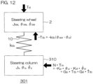
- FIG. 12 is a schematic diagram illustrating a two-inertia model 301 corresponding to the electric power steering system 1 in automatic steering mode or in cooperative steering mode.
- the two-inertia model 301 includes a steering wheel 2, a torsion bar 10, and a steering column 310.
- the steering wheel 2 has inertia of the steering wheel 2 (hereinafter referred to as steering wheel inertia J sw ).
- the steering column 310 has column inertia J p .
- the column inertia J p includes inertia of the worm wheel 21 (worm wheel inertia), inertia of the worm gear 20 (worm gear inertia), inertia of the shaft of the electric motor 18 (motor shaft inertia), inertia of the pinion shaft 13 (pinion shaft inertia), and so forth.
- ⁇ sw is a rotational angle of the steering wheel 2 (hereinafter referred to as wheel angle ⁇ sw ), and d ⁇ sw /dt is angular velocity of the steering wheel 2 (hereinafter referred to as wheel angular velocity d ⁇ sw /dt).
- ⁇ ⁇ is a rotational angle of the steering column 310 (hereinafter referred to as column angle ⁇ p ), and d ⁇ p /dt is angular velocity of the steering column 310 (hereinafter referred to as column angular velocity d ⁇ p /dt).
- T d driver torque applied to the steering wheel 2 by the driver
- k tb stiffness of the torsion bar 10 (hereinafter referred to as the torsion bar stiffness k tb )
- T tb is the steering torque (torsion bar torque)
- N is the reduction ratio of the speed reducer 19
- N ⁇ T m is a driving torque N ⁇ T m that is equivalent to the output shaft torque command value N ⁇ T m .
- driver torque T d is applied to the steering wheel 2 by the driver, and also -T tb , which is the sign-inverted value of the steering torque T tb , is applied from the torsion bar 10.
- the driving torque N ⁇ T m is applied to the steering column 310 from the electric motor 18.
- N ⁇ T m (-K p ⁇ p - K d ⁇ d ⁇ p /dt + G p ⁇ T tb + G d ⁇ dT tb /dt) holds.
- the steering torque T tb and the road load torque T rl are applied to the steering column 310 in addition to the driving torque N ⁇ T m .
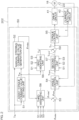
- FIG. 13 is a control block diagram of a feedback control system of the electric power steering system 1 in automatic steering mode or in cooperative steering mode, and is a block diagram representing a model of a column and a steering wheel that are objects of control.
- FIG. 13 is a block diagram corresponding to FIG. 12 and Expressions (10a) and (10b) described later.
- the feedback control torque T fb is generated by PD control with respect to deviation between the integrated angle command value ⁇ sin following low-pass filter processing and the column angle ⁇ ⁇ (actual steering angle ⁇ ).
- the proportional gain K p and the differential gain K d each include the column inertia J p , which will be described later.
- This added value (T fb + G d ⁇ dT tb /dt + G p ⁇ T tb ) is equivalent to the output shaft torque command value N ⁇ T m corresponding to a value obtained by multiplying the angular acceleration of the column angle ⁇ ⁇ (hereinafter referred to as column angular acceleration d 2 ⁇ p /dt 2 ) by the column inertia J p .
- a driving torque corresponding to this output shaft torque command value N ⁇ T m is applied from the electric motor 18 to the steering column 310.
- the sum of a value G d ⁇ dT tb /dt obtained by multiplying the differential value of this steering torque T tb by the first gain G d , and a value G p ⁇ T tb obtained by multiplying this steering torque T tb by the second gain G p is fed back as resonance control torque T res .
- the steering torque T tb and the driver torque T d are input to the steering wheel 2, having inertia that is J sw , the steering wheel 2 rotates thereby.
- K p J p ⁇ ⁇ 4 ⁇ sw 2 11 a
- K d J p ⁇ 4 ⁇ ⁇ 3 ⁇ sw 2 11 b
- G p J p ⁇ ⁇ 2 4 ⁇ 2 + 2 ⁇ ⁇ 2 ⁇ sw 2 ⁇ ⁇ sw 2 / k tb 11 c
- G d J p ⁇ 4 ⁇ ⁇ 1 ⁇ ⁇ 2 ⁇ sw 2 / k tb 11 d
- G N ⁇ T m ⁇ p s 2 + ⁇ sw 2 J p s 2 + 2 ⁇ ⁇ s + ⁇ 2 2 12 a
- G N ⁇ T m ⁇ ⁇ sw ⁇ sw 2 J p s 2 + 2 ⁇ ⁇ s + ⁇ 2 12 b
- ⁇ sw is the natural frequency (resonant frequency) of the steering wheel 2 determined by the mechanical characteristics of the steering wheel 2. Also, ⁇ is a variable that represents the resonant frequency of the system.
- the resonant frequency ⁇ and damping characteristics can be optionally set, and accordingly the responsivity can be changed. Specifically, the greater a value the resonant frequency ⁇ is set to, the faster the responsivity becomes.
- load compensation is performed, but load compensation does not necessarily have to be performed.
- switching can be performed among the cooperative steering mode in which the electric motor 18 can be controlled based on the integrated angle command value ⁇ sint , the manual steering mode in which the electric motor 18 can be controlled based only on the assist torque command value T as , and the automatic steering mode in which the electric motor 18 can be controlled based only on the automatic steering command value ⁇ adac .
- the electric motor 18 can be controlled based only on the assist torque command value T as .
- the electric motor 18 is controlled based only on the assist torque command value T as , and accordingly the driver can receive the actual road load torque (road reaction torque).
- the basic torque command value (T fb ) is computed based on the integrated angle command value ⁇ sint , and the basic torque command value (T fb ) is corrected by the disturbance torque estimation value ⁇ T lc computed by the disturbance torque estimation unit 66. That is to say, in the first embodiment described above, the nonlinear disturbance torque (torque other than the motor torque) that occurs as a disturbance in the output shaft 9 is compensated for (load compensation). Accordingly, the effects of disturbance torque on the angle control performance can be suppressed. Thus, highly precise angle control can be realized.
- an electric power steering system including an angle control unit having a function of performing load compensation and also receiving K R ⁇ T tb as feedback, as described in Patent Document 1, will be referred to as a conventional example.
- K R is vibration suppression gain
- K R ⁇ T tb is vibration suppression torque.
- the angle control unit is provided with a feedback control unit and a feedforward control unit, but an assumption will be made that the feedforward control unit is not provided, in order to simplify description.
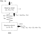
- FIG. 14 is a schematic diagram illustrating a two-inertia model 302 corresponding to the conventional example
- driver torque T d is applied to the steering wheel 2 by the driver, and also s-T tb , which is the sign-inverted value of the steering torque T tb , is applied from the torsion bar 10.
- K p is proportional gain in the conventional example
- K d is differential gain in the conventional example
- K p J p ⁇ ⁇ sw 2 14 a
- K d J p ⁇ 4 ⁇ sw 14 b
- electric power steering system according to second embodiment an electric power steering system to which a motor control device according to a second embodiment of the present invention is applied (hereinafter, referred to as "electric power steering system according to second embodiment") will be described.
- a configuration of a motor control ECU 202A is different from the configuration of the motor control ECU 202 in FIG. 2 .
- the automatic steering command value ⁇ adac and the mode setting signals S1, S2, S3 are not given from the host ECU 201 (see FIG. 1 ) to the motor control ECU 202A.
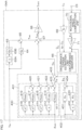
- FIG. 15 is a block diagram illustrating the configuration of the motor control ECU 202A used in the electric power steering system according to the second embodiment.
- the motor control ECU 202A includes a microcomputer 50A, the drive circuit (inverter circuit) 41 that is controlled by the microcomputer 50A and that supplies electric power to the electric motor 18, and the current detection circuit 42 that detects a current flowing through the electric motor 18 (hereinafter referred to as "motor current I").
- the microcomputer 50A includes a CPU and memory (such as ROM, RAM, non-volatile memory, and so forth), and functions as a plurality of functional processing units by executing a predetermined program.
- the plurality of functional processing units include an assist torque command value setting unit 151, a first reduction ratio multiplication unit 152, a first torque computation unit 153, a second torque computation unit 154, a first torque addition unit 155, a disturbance torque estimation unit 156, a second torque addition unit 157, a first reduction ratio division unit 158, a torque control unit 159, a second reduction ratio multiplication unit 160, a rotational angle computation unit 161, and a second reduction ratio division unit 162.
- the second reduction ratio multiplication unit 160 multiplies the motor torque command value T m computed by the first reduction ratio division unit 158 by the reduction ratio N of the speed reducer 19, to convert the motor torque command value T m into the output shaft torque command value N ⁇ T m that acts on the output shaft 9.
- the rotational angle computation unit 161 computes the rotor rotational angle ⁇ m of the electric motor 18 based on the output signal from the rotational angle sensor 23.
- the second reduction ratio division unit 162 converts the rotor rotational angle ⁇ m computed by the rotational angle computation unit 161 into the rotational angle (actual steering angle) ⁇ of the output shaft 9 by dividing the rotor rotational angle ⁇ m by the speed reduction ratio N.
- the assist torque command value setting unit 151 sets the assist torque command value T as that is a target value of the assist torque necessary for manual operations. Actions of the assist torque command value setting unit 151 are similar to those of the assist torque command value setting unit 51 in FIG. 2 , and accordingly detailed description thereof will be omitted.
- the first reduction ratio multiplication unit 152 multiplies the assist torque command value T as set by the assist torque command value setting unit 151 by the reduction ratio N, to convert the assist torque command value T as for the electric motor 18 into an assist torque command value N ⁇ T as for the output shaft 9.
- the assist torque command value T as is given to the second torque addition unit 157.
- the first torque computation unit 153 includes a differential computation unit 153A and a first gain multiplication unit 153B.
- the differential computation unit 153A computes the time differential value dT tb /dt of the steering torque T tb .
- the first gain multiplication unit 153B computes a first torque G d ⁇ dT tb /dt by multiplying the differential value dT tb /dt computed by the differential computation unit 153A by the first gain G d .
- the second torque computation unit 154 computes a second torque G p ⁇ T tb by multiplying the steering torque T tb by the second gain G p .
- the resonance control torque T res is given to the second torque addition unit 157.
- a disturbance torque estimation unit 156 estimates the disturbance torque (disturbance load) T lc , the steering angle ⁇ , and the steering angle differential value (angular velocity) d ⁇ /dt, based on the output shaft torque command value N ⁇ T m and the actual steering angle ⁇ .
- the estimated values of the disturbance torque T lc , the steering angle ⁇ , and the steering angle differential value (angular velocity) d ⁇ /dt are represented by ⁇ T lc , ⁇ , and d ⁇ /dt, respectively.
- the configuration and actions of the disturbance torque estimation unit 156 are similar to those of the disturbance torque estimation unit 66 in FIG. 5 , and accordingly detailed description thereof will be omitted.
- the disturbance torque estimation value ⁇ T lc computed by the disturbance torque estimation unit 156 is given to the second torque addition unit 157 as a disturbance torque compensation value.
- the output shaft torque command value N ⁇ T m is given to the first reduction ratio division unit 158.
- the first reduction ratio division unit 158 computes the motor torque command value T m by dividing the output shaft torque command value N ⁇ T m by the reduction ratio N. This motor torque command value T m is given to the torque control unit 159.
- the torque control unit 159 drives the drive circuit 41 such that the motor torque of the electric motor 18 is brought closer the motor torque command value T m .
- the configuration and actions of the torque control unit 159 are similar to those of the torque control unit 55 in FIG. 2 , and accordingly detailed description thereof will be omitted.
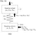
- FIG. 16 is a schematic diagram illustrating a two-inertia model 303 corresponding to the electric power steering system including the motor control ECU 202A illustrated in FIG. 15 .
- driver torque T d is applied to the steering wheel 2 by the driver, and also -T tb , which is the sign-inverted value of the steering torque T tb , is applied from the torsion bar 10.
- G p J p ⁇ ⁇ 2 ⁇ ⁇ sw 2 k tb 17 a
- G d J p ⁇ 2 ⁇ ⁇ k tb 17 b
- G N ⁇ T m ⁇ ⁇ p s 2 + ⁇ sw 2 J p s 2 s 2 + 2 ⁇ ⁇ s + ⁇ 2 2 18 a
- G N ⁇ T m ⁇ ⁇ sw ⁇ sw 2 J p s 2 s 2 + 2 ⁇ ⁇ s + ⁇ 2 18 b
- the resonant frequency ⁇ and the damping ratio ⁇ can be optionally set.
- the resonant frequency ⁇ and damping characteristics can be optionally set, and accordingly the responsivity can be changed. Specifically, the greater a value the resonant frequency ⁇ is set to, the faster the responsivity becomes.
- electric power steering system according to third embodiment an electric power steering system to which a motor control device according to a third embodiment of the present invention is applied (hereinafter, referred to as "electric power steering system according to third embodiment") will be described.
- the electric power steering system according to the third embodiment has the same overall configuration as that illustrated in FIG. 1 .
- the configuration of the motor control ECU 202 is similar to the configuration of the motor control ECU 202 in FIG. 2 , but the configuration of the angle control unit 54 in the motor control ECU 202 in FIG. 2 is different.
- the configurations 51 to 53 and 55 to 59 in FIG. 2 , other than the angle control unit 54, are the same in the electric power steering system according to the third embodiment.
- FIG. 17 is a block diagram illustrating a configuration of an angle control unit 54A used in the motor control ECU 202 in the electric power steering system according to the third embodiment.
- portions corresponding to those in FIG. 5 described above are denoted by the same signs as those in FIG. 5 .
- the angle control unit 54A in FIG. 17 computes an integrated motor torque command value T mint based on the integrated angle command value ⁇ sint , the steering torque T tb , and the output signal of the rotational angle sensor 23.
- the angle control unit 54A in FIG. 17 differs in comparison with the angle control unit 54 in FIG. 5 in that the low-pass filter (LPF) 61 in FIG. 5 is not provided, and that a configuration of a feedback control unit 400 is different from the configuration of the feedback control unit 62 in FIG. 5 .
- LPF low-pass filter
- the actions of the first torque computation unit 63, the second torque computation unit 64, the first torque addition unit 65, the disturbance torque estimation unit 66, the first reduction ratio division unit 68, the reduction ratio multiplication unit 69, the rotational angle computation unit 70, and the second reduction ratio division unit 71 in FIG. 17 are the same as the actions of the corresponding units in FIG. 5 , and accordingly description thereof will be omitted.
- the feedback control unit 400 includes a target torque computation unit 401, a feedback torque computation unit 402, and a torque deviation computation unit 403.
- the target torque computation unit 401 computes a target torque T ta by performing predetermined computation on the integrated angle command value ⁇ sint computed by the integrated angle command value computation unit 53 (see FIG. 2 ).
- the target torque computation unit 401 includes a proportional gain multiplication unit 411, a first-order differential computation unit 412, a first-order differential gain multiplication unit 413, a second-order differential computation unit 414, a second-order differential gain multiplication unit 415, a third-order differential computation unit 416, a third-order differential gain multiplication unit 417, a fourth-order differential computation unit 418, a fourth-order differential gain multiplication unit 419, and first to fourth addition units 420 to 423.
- the proportional gain multiplication unit 411 multiplies the integrated angle command value ⁇ sint by a proportional gain K 0dot .
- the first-order differential computation unit 412 computes a first-order differential value d ⁇ sint /dt of the integrated angle command value ⁇ sint .
- the first-order differential gain multiplication unit 413 multiplies the first-order differential value d ⁇ sint /dt computed by the first-order differential computation unit 412 by a first-order differential gain K 1dot .
- the second-order differential computation unit 414 computes a second-order differential value d 2 ⁇ sint /dt 2 of the integrated angle command value ⁇ sint .
- the second-order differential gain multiplication unit 415 multiplies the second-order differential value d 2 ⁇ sint /dt 2 computed by the second-order differential computation unit 414 by a second-order differential gain K 2dot .
- the third-order differential computation unit 416 computes a third-order differential value d 3 ⁇ sint /dt 3 of the integrated angle command value ⁇ sint .
- the third-order differential gain multiplication unit 417 multiplies the third-order differential value d 3 ⁇ sint /dt 3 computed by the third-order differential computation unit 416 by a third-order differential gain K 3dot .
- the fourth-order differential computation unit 418 computes a fourth-order differential value d 4 ⁇ sint /dt 4 of the integrated angle command value ⁇ sint .
- the fourth-order differential gain multiplication unit 419 multiplies the fourth-order differential value d 4 ⁇ sint /dt 4 computed by the fourth-order differential computation unit 418 by a fourth-order differential gain K 4dot .
- the first addition unit 420 adds a multiplication result K 4dot ⁇ d 4 ⁇ sint /dt 4 of the fourth-order differential gain multiplication unit 419 and a multiplication result K 3dot ⁇ d 3 ⁇ sint /dt 3 of the third-order differential gain multiplication unit 417.
- the second addition unit 421 adds the addition result of the first addition unit 420 (K 3dot ⁇ d 3 ⁇ sint /dt 3 + K 4dot ⁇ d 4 ⁇ sint /dt 4 ) and the multiplication result K 2dot ⁇ d 2 ⁇ sint /dt 2 of the second-order differential gain multiplication unit 415.
- the third addition unit 422 adds the addition result of the second addition unit 421 (K 2dot ⁇ d 2 ⁇ sint /dt 2 + K 3dot ⁇ d 3 ⁇ sint /dt 3 + K 4dot ⁇ d 4 ⁇ sint /dt 4 ) and the multiplication result K 1dot ⁇ d ⁇ sint /dt of the first-order differential gain multiplication unit 413.
- the fourth addition unit 423 adds the addition result of the third addition unit 422 (K 1dot ⁇ sint /dt + K 2dot ⁇ d 2 ⁇ sint /dt 2 + K 3dot ⁇ d 3 ⁇ sint /dt 3 + K 4dot ⁇ d 4 ⁇ sint /dt 4 ) and the multiplication result K 0dot ⁇ sint of the proportional gain multiplication unit 411, thereby computing the target torque T ta .
- the target torque T ta is expressed as (K 0dot ⁇ sint + (K 1dot ⁇ sint /dt + K 2dot ⁇ d 2 ⁇ sint /dt 2 + K 3dot ⁇ d 3 ⁇ sint /dt 3 + K 4dot ⁇ d 4 ⁇ sint /dt 4 ).
- the feedback torque computation unit 402 computes feedback torque T fe by performing predetermined computation with respect to the actual steering angle ⁇ .
- the feedback torque computation unit 402 includes a proportional gain multiplication unit 431, a differential computation unit 432, a differential gain multiplication unit 433, and an addition unit 434.
- the proportional gain multiplication unit 431 multiplies the actual steering angle ⁇ computed by the second reduction ratio division unit 71 by the proportional gain K p .
- the differential computation unit 432 computes a time differential value d ⁇ /dt of the actual steering angle ⁇ .
- the differential gain multiplication unit 433 multiplies the differential value d ⁇ /dt computed by the differential computation unit 432 by the differential gain K d .
- the addition unit 434 adds the multiplication result K p ⁇ of the proportional gain multiplication unit 431 and the multiplication result d ⁇ /dt of the differential gain multiplication unit 433, thereby computing feedback control torque T fe .
- the feedback torque T fe is (K p ⁇ + K d ⁇ d ⁇ /dt).
- the actual steering angle ⁇ computed by the second reduction ratio division unit 71 is input to the feedback torque computation unit 402.
- the steering angle estimation value ⁇ computed by the disturbance torque estimation unit 66 may be input to the feedback torque computation unit 402 instead of the actual steering angle ⁇ .
- the feedback torque T fe is (K p ⁇ + K d ⁇ d ⁇ /dt).
- the torque deviation computation unit 403 computes the feedback control torque T fb by subtracting the feedback torque T fe from the target torque T ta .
- the feedback control torque T fb is a control torque for bringing the actual steering angle ⁇ closer to the integrated angle command value ⁇ sint .
- the feedback control torque T fb is an example of "basic torque command value" according to the present invention.
- the integrated steering torque command value T sint is given to the first reduction ratio division unit 68.
- the first reduction ratio division unit 68 computes the integrated motor torque command value T mint by dividing the integrated steering torque command value T sint by the reduction ratio N.
- This integrated motor torque command value T mint is given to the second weighting unit 57 (see FIG. 2 ).
- FIG. 18 is a schematic diagram illustrating a two-inertia model 304 corresponding to the electric power steering system according to the third embodiment in automatic steering mode or in cooperative steering mode.
- the driver torque T d is applied to the steering wheel 2 by the driver, and also -T tb , which is the sign-inverted value of the steering torque T tb , is applied from the torsion bar 10.
- the driving torque N ⁇ T m is applied to the steering column 310 from the electric motor 18.
- the steering torque T tb and the road load torque T rl are applied to the steering column 310 in addition to the driving torque N ⁇ T m .
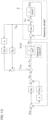
- FIG. 19 is a control block diagram of a feedback control system of the electric power steering system according to the third embodiment in automatic steering mode or in cooperative steering mode, and is a block diagram representing a model of the column and the steering wheel that are objects of control.
- FIG. 19 is a block diagram corresponding to FIG. 18 and Expressions (19a) and (19b) described later.
- the feedback torque T fe computed by the feedback torque computation unit 402 based on the first column angle ⁇ p (actual steering angle ⁇ ), is subtracted from the target torque T ta computed by the target torque computation unit 401 based on the integrated angle command value ⁇ sint , thereby generating the feedback control torque T fb ( T ta - T fe ).
- the proportional gain K p and the differential gain K d each include the column inertia J p , which will be described later.
- This added value (T fb + G d ⁇ dT tb /dt + G p ⁇ T tb ) is equivalent to the output shaft torque command value N ⁇ T m corresponding to a value obtained by multiplying the angular acceleration of the column angle ⁇ ⁇ (hereinafter referred to as column angular acceleration d 2 ⁇ p /dt 2 ) by the column inertia J p .
- a driving torque corresponding to this output shaft torque command value N ⁇ T m is applied from the electric motor 18 to the steering column 310.
- the sum of a value G d ⁇ dT tb /dt obtained by multiplying the differential value of this steering torque T tb by the first gain G d , and a value G p ⁇ T tb obtained by multiplying this steering torque T tb by the second gain G p is fed back as resonance control torque T res .
- the steering torque T tb and the driver torque T d are input to the steering wheel 2, having inertia that is J sw , the steering wheel 2 rotates thereby.
- the transfer function G( ⁇ sint ⁇ ⁇ p ) from the integrated angle command value ⁇ sint to the column angle ⁇ ⁇ is expressed by the following Expression (20a)
- the transfer function G( ⁇ sint ⁇ ⁇ sw ) from the integrated angle command value ⁇ sint to the wheel angle ⁇ sw is expressed by the following Expression (20b).
- G ⁇ sint ⁇ ⁇ p s 2 + ⁇ sw 2 K 4 dot s 4 + K 3 dot s 3 + K 2 dot s 2 + K 1 dot s + K 0 dot J p s 2 + 2 ⁇ ⁇ s + ⁇ 2 2 20 a
- G ⁇ sint ⁇ ⁇ sw ⁇ sw 2 K 4 dot s 4 + K 3 dot s 3 + K 2 dot s 2 + K 1 dot s + K 0 dot J p s 2 + 2 ⁇ ⁇ s + ⁇ 2 2 20 b
- the gain K p for the angle ⁇ sint ( ⁇ sin in FIG. 5 ) and the gain K d for the angular velocity d ⁇ sint /dt (d ⁇ sin /dt in FIG. 5 ) on the command value side are the same as the gain K p for the angle ⁇ and the gain K d for the angular velocity d ⁇ /dt on the feedback side, respectively. That is to say, a common gain is set on the command value side and the feedback side.
- different gains can be set on the command value side and the feedback side.
- different gains are preferably set on the command value side and the feedback side. In other words, it is preferable that the gain used in the computation of the target torque T ta and the gain used in the computation of the feedback torque T fe are different from each other.
- the proportional gain K 0dot , the first-order differential gain K 1dot , the second-order differential gain K 2dot , the third-order differential gain K 3dot , and the fourth-order differential gain K 4dot are set to values as in the following Expression (22).
- the transfer function G( ⁇ sint ⁇ ⁇ p ) from the integrated angle command value ⁇ sint to the column angle ⁇ p is expressed by the following Expression (23a), and the transfer function G( ⁇ sint ⁇ ⁇ sw ) from the integrated angle command value ⁇ sint to the wheel angle ⁇ sw is expressed by the following Expression (23b).
- G ⁇ sint ⁇ ⁇ p s 2 + ⁇ sw 2 ⁇ ⁇ 4 ⁇ sw 2 s 2 + 2 ⁇ ⁇ s + ⁇ 2 2 23a
- G ⁇ sint ⁇ ⁇ sw ⁇ 4 s 2 + 2 ⁇ ⁇ s + ⁇ 2 2 23b
- the wheel angle ⁇ sw responds with a fourth-order lag.
- the resonant frequency ⁇ and the damping ratio ⁇ can be optionally set, in the same way as in the first embodiment.
- the proportional gain K 0dot , the first-order differential gain K 1dot , the second-order differential gain K 2dot , the third-order differential gain K 3dot , and the fourth-order differential gain K 4dot are set to values as in the following Expression (24).
- the transfer function G( ⁇ sint ⁇ ⁇ p ) from the integrated angle command value ⁇ sint to the column angle ⁇ ⁇ is expressed by the following Expression (25a), and the transfer function G( ⁇ sint ⁇ ⁇ sw ) from the integrated angle command value ⁇ sint to the wheel angle ⁇ sw is expressed by the following Expression (25b).
- G ⁇ sint ⁇ ⁇ p s 2 + ⁇ sw 2 ⁇ ⁇ 3 ⁇ sw 2 s + ⁇ 3 25a
- G ⁇ sint ⁇ ⁇ sw ⁇ 3 s + ⁇ 3 25b
- the wheel angle ⁇ sw responds with a third-order lag.
- the resonant frequency ⁇ can be optionally set, in the same way as in the first embodiment.
- the proportional gain K 0dot , the first-order differential gain K 1dot , the second-order differential gain K 2dot , the third-order differential gain K 3dot , and the fourth-order differential gain K 4dot are set as in the following Expression (26).
- K 4dot O
- the transfer function G( ⁇ sint ⁇ ⁇ p ) from the integrated angle command value ⁇ sint to the column angle ⁇ ⁇ is expressed by the following Expression (27a), and the transfer function G( ⁇ sint ⁇ ⁇ sw ) from the integrated angle command value ⁇ sint to the wheel angle ⁇ sw is expressed by the following Expression (27b).
- G ⁇ sint ⁇ ⁇ p s 2 + ⁇ sw 2 ⁇ ⁇ 2 ⁇ sw 2 s 2 + 2 ⁇ ⁇ s + ⁇ 2 27a
- G ⁇ sint ⁇ ⁇ sw ⁇ 2 s 2 + 2 ⁇ ⁇ s + ⁇ 2 27b
- the wheel angle ⁇ sw responds with a second-order lag.
- the resonant frequency ⁇ and the damping ratio ⁇ can be optionally set, in the same way as in the first embodiment.
- the proportional gain K 0dot , the first-order differential gain K 1dot , the second-order differential gain K 2dot , the third-order differential gain K 3dot , and the fourth-order differential gain K 4dot are set as in the following Expression (28).
- the transfer function G( ⁇ sint ⁇ ⁇ p ) from the integrated angle command value ⁇ sint to the column angle ⁇ ⁇ is expressed by the following Expression (29a), and the transfer function G( ⁇ sint ⁇ ⁇ sw ) from the integrated angle command value ⁇ sint to the wheel angle ⁇ sw is expressed by the following Expression (29b).
- G ⁇ sint ⁇ ⁇ p s 2 + ⁇ sw 2 ⁇ ⁇ ⁇ sw 2 s + ⁇ 29a
- G ⁇ sint ⁇ ⁇ sw ⁇ s + ⁇ 29b
- the wheel angle ⁇ sw responds with a first-order lag.
- the resonant frequency ⁇ can be optionally set, in the same way as in the first embodiment.
- a low-pass filter of first or higher order, having a cutoff frequency no higher than ⁇ , is preferably provided between the integrated angle command value computation unit 53 (see FIG. 2 ) and the angle control unit 54A (see FIG. 17 ).
- the proportional gain K 0dot , the first-order differential gain K 1dot , the second-order differential gain K 2dot , the third-order differential gain K 3dot , and the fourth-order differential gain K 4dot are set as in the following Expression (30).
- the transfer function G( ⁇ sint ⁇ ⁇ p ) from the integrated angle command value ⁇ sint to the column angle ⁇ ⁇ is expressed by the following Expression (31a), and the transfer function G( ⁇ sint ⁇ ⁇ sw ) from the integrated angle command value ⁇ sint to the wheel angle ⁇ sw is expressed by the following Expression (31b).
- G ⁇ sint ⁇ ⁇ p s 2 + ⁇ sw 2 ⁇ sw 2 31 a
- G ⁇ sint ⁇ ⁇ sw 1 31 b
- a low-pass filter of second or higher order, having a cutoff frequency no higher than ⁇ , is preferably provided between the integrated angle command value computation unit 53 (see FIG. 2 ) and the angle control unit 54A (see FIG. 17 ).
- load compensation is performed, but load compensation does not necessarily have to be performed.
- switching can be performed among the cooperative steering mode in which the electric motor 18 can be controlled based on the integrated angle command value ⁇ sint , the manual steering mode in which the electric motor 18 can be controlled based only on the assist torque command value T as , and the automatic steering mode in which the electric motor 18 can be controlled based only on the automatic steering command value ⁇ adac .
- the electric motor 18 can be controlled based only on the assist torque command value T as .
- a dead band processing unit may be provided for at least one of the steering torque T tb input to the first torque computation units 63 and 153, and the steering torque T tb input to the second torque computation units 64 and 154. The reason for providing the dead band processing unit will be described later.
- the dead band processing unit is provided for at least one of the steering torque T tb input to the first torque computation unit 63 (see FIG. 5 and FIG. 17 ) and the steering torque T tb input to the second torque computation unit 64 (see FIG. 5 and FIG. 17 ) in the first embodiment (third embodiment).
- the dead band processing unit is provided for at least one of the steering torque T tb input to the first torque computation unit 63 (see FIG. 5 and FIG. 17 ) and the steering torque T tb input to the second torque computation unit 64 (see FIG. 5 and FIG. 17 ) in the first embodiment (third embodiment).
- FIG. 20 , FIG. 23 , and FIG. 24 only the parts of the configurations of the angle control units 54, 54A that are related to the computation of the resonance control torque T res are illustrated.
- FIG. 20 is a block diagram illustrating an example in which a dead band processing unit 501 is provided upstream of the second torque computation unit 64.
- the steering torque T tb is input to the dead band processing unit 501.
- FIG. 21 shows an example of input/output characteristics of the dead band processing unit 501.
- the dead band processing unit 501 outputs zero as a steering torque T tb,de following dead band processing in a case in which the steering torque T tb is within a range of -W/2 or greater and W/2 or smaller (dead band region).
- the dead band processing unit 501 In a region in which the steering torque T tb is smaller than -W/2, the dead band processing unit 501 outputs [T tb + (W/2)] as the steering torque T tb,de following the dead band processing. In a region in which the steering torque T tb is greater than W/2, the dead band processing unit 501 outputs [T tb - (W/2)] as the steering torque T tb,de following the dead band processing.
- the dead band width W is set in advance.
- the second torque computation unit 64 computes second torque G p ⁇ T tb,de by multiplying the steering torque T tb,de following the dead band processing by the second gain G p . Accordingly, in this case, the resonance control torque T ress is G d ⁇ dT tb /dt + G p ⁇ T tb,de .
- the dead band processing unit 501 may output a value close to zero as the steering torque T tb,de following the dead band processing.
- the input/output characteristics of the dead band processing unit 501 may be characteristics such as shown in FIG. 22 .
- the input/output characteristics of the dead band processing unit 501 may be characteristics such that, within a dead band region (a range of -W/2 or greater and W/2 or smaller) in which the absolute value of the steering torque T tb is small, the absolute value of the steering torque T tb,de following the dead band processing gradually increases quadratically as the absolute value of the steering torque T tb increases, and, in a range in which the absolute value of the steering torque T tb is greater than the dead band region, the absolute value of the steering torque T tb,de following the dead band processing increases linearly as the absolute value of the steering torque T tb increases.
- a dead band region a range of -W/2 or greater and W/2 or smaller
- the dead band processing unit 501 may be provided upstream of both the first torque computation unit 63 and the second torque computation unit 64, as illustrated in FIG. 23 .
- the first torque computation unit 63 computes the first torque Gd ⁇ dT tb,de /dt by multiplying the time differential value dT tb,de /dt of the steering torque T tb,de following the dead band processing by the first gain G d .
- the second torque computation unit 64 computes the second torque by multiplying the steering torque T tb,de following the dead band processing by the second gain G p . Accordingly, in this case, the resonance control torque T ress is G d ⁇ dT tb,de /dt + G p ⁇ T tb,de .
- the dead band processing unit 501 may be provided upstream of the first torque computation unit 63, as illustrated in FIG. 24 .
- the first torque computation unit 63 computes the first torque G d ⁇ dT tb,de /dt by multiplying the time differential value dT tb,de /dt of the steering torque T tb,de following the dead band processing by the first gain G d . Accordingly, in this case, the resonance control torque T ress is G d ⁇ dT tb,de /dt + G p ⁇ T tb .
- the steering torque T tb (primarily the sum of the driver torque T d applied to the steering wheel 2 by the driver and the force generated by steering inertia) may be offset by friction and so forth. Accordingly, even when the absolute value of the actual steering torque T tb is zero or close to zero, the absolute value of the steering torque T tb that is detected by the torque sensor 12 may be greater than the absolute value of the actual steering torque T tb .
- the dead band processing unit 501 when the dead band processing unit 501 is provided to at least one of the steering torque T tb input to the first torque computation unit 63 and the second torque computation unit 64, the following effects can be obtained. That is to say, in a range in which the resonance of the steering wheel 2 is great (a range in which the absolute value of the steering torque T tb is great), resonance control based on the resonance control torque T res can be performed. On the other hand, in a range in which the resonance of the steering wheel 2 is small and resonance control is not necessary (a range in which the absolute value of the steering torque T tb is small), steering angle deviation based on offset of the steering torque T tb can be suppressed.
- the dead band processing unit 501 described above may be provided only upstream from the second torque computation unit 154 ( FIG. 15 ) of the second embodiment, or the dead band processing unit 501 described above may be provided only upstream from the first torque computation unit 153 ( FIG. 15 ) of the second embodiment. Also, the dead band processing unit 501 described above may be provided upstream from both the first torque computation unit 153 ( FIG. 15 ) and the second torque computation unit 154 ( FIG. 15 ) of the second embodiment.
- the first weighting unit 56, the second weighting unit 57, and the third weighting unit 58 are provided, but the third weighting unit 58 may be omitted.
- the third weighting unit 58 may be omitted.
- two types of steering modes i.e., the manual steering mode and the cooperative steering mode, will be available.
- providing an angle sensor for detecting the rotational angle of the steering wheel 2 enables similar control without using the steering torque T tb by feedback of the relative angle between the steering wheel 2 and the steering column 310 and the relative speed between the steering wheel 2 and the steering column 310 (which may be detected by a speed sensor or may be the differential value of the relative angle).
- G p ' Gp ⁇ k tb
- G d ' Gd ⁇ k tb hold.
Landscapes
- Engineering & Computer Science (AREA)
- Power Engineering (AREA)
- Chemical & Material Sciences (AREA)
- Combustion & Propulsion (AREA)
- Transportation (AREA)
- Mechanical Engineering (AREA)
- Steering Control In Accordance With Driving Conditions (AREA)
Abstract
Description
- This invention relates to a motor control device that controls an electric motor that applies steering force to an output shaft linked to a steering wheel via a torsion bar.
-
Patent Document 1 discloses that a disturbance torque, which is a torque other than a motor torque that acts on a motor-driven object, is subtracted from a basic torque command value, and a vibration suppression torque obtained by multiplying steering torque (torsion bar torque) by a predetermined vibration suppression gain is added to the subtraction results, thereby computing a torque command value for an output shaft. The basic torque command value includes a feedback torque obtained by performing PD (proportional derivative) computation with respect to deviation between an automatic steering angle command value and a steering angle detection value or a steering angle estimation value. - In the invention described in
Patent Document 1, vibration is suppressed by setting a vibration suppression gain, a proportional gain used in PD computation, and a differential gain used in PD computation, to respective predetermined values. - Patent Document 1:
Japanese Unexamined Patent Application Publication No. 2018-183046 JP 2018-183046 A - In the invention described in
Patent Document 1, vibration can be suppressed, but resonant frequency of the system is fixed to mechanical natural frequency (resonant frequency) of a steering wheel, and accordingly the resonant frequency of the system cannot be optionally set. - An object of this invention is to provide a motor control device that enables the resonant frequency of the system to be optionally set.
- An embodiment of the present invention provides a motor control device that controls an electric motor that applies steering force to an output shaft linked to a steering wheel via a torsion bar, the motor control device including a steering torque detection unit that detects a steering torque applied to the steering wheel, and a motor torque command value setting unit that sets a motor torque command value that is a target value of motor torque of the electric motor, in which the motor torque command value setting unit includes a basic torque command value setting unit that sets a basic torque command value, a correction unit that corrects the basic torque command value set by the basic torque command value setting unit, using a resonance control torque, and a motor torque command value computation unit that computes the motor torque command value based on the basic torque command value following correction by the correction unit, and the resonance control torque is set using a first torque obtained by multiplying a differential value of the steering torque by a predetermined first gain, and a second torque obtained by multiplying the steering torque by a predetermined second gain.
- According to this configuration, the resonant frequency of the system can be optionally set.
- The above and other objects, features, and effects of the present invention will become apparent from the following description of an embodiment that will be given with reference to the accompanying drawings.
-
- [
FIG. 1] FIG. 1 is a schematic diagram illustrating a schematic configuration of an electric power steering system to which a motor control device according to a first embodiment of the present invention is applied. - [
FIG. 2] FIG. 2 is a block diagram for describing an electrical configuration of a motor control ECU. - [
FIG. 3] FIG. 3 is a graph showing an example of setting an assist torque command value Tas with respect to steering torque Ttb. - [
FIG. 4] FIG. 4 is a schematic diagram illustrating an example of a reference EPS model that is used in a manual steering command value generation unit. - [
FIG. 5] FIG. 5 is a block diagram illustrating a configuration of an angle control unit. - [
FIG. 6] FIG. 6 is a schematic diagram illustrating an example of a configuration of a physical model of the electric power steering system. - [
FIG. 7] FIG. 7 is a block diagram illustrating a configuration of a disturbance torque estimation unit. - [
FIG. 8] FIG. 8 is a block diagram illustrating a configuration of a torque control unit. - [
FIG. 9] FIG. 9 is a graph showing a setting example of a first weight W1 that is set when each mode setting signal S1, S2, S3 is input. - [
FIG. 10] FIG. 10 is a graph showing a setting example of a second weight W2 that is set when each mode setting signal S1, S2, S3 is input. - [
FIG. 11] FIG. 11 is a graph showing a setting example of a third weight W 3 that is set when each mode setting signal S1, S2, S3 is input. - [
FIG. 12] FIG. 12 is a schematic diagram illustrating a two-inertia model corresponding to the electric power steering system in automatic steering mode or in cooperative steering mode. - [
FIG. 13] FIG. 13 is a control block diagram of a feedback control system of the electric power steering system in automatic steering mode or cooperative steering mode, and is a block diagram representing a model of a column and a steering wheel that are objects of control. - [
FIG. 14] FIG. 14 is a schematic diagram illustrating a two-inertia model corresponding to a conventional example. - [
FIG. 15] FIG. 15 is a block diagram illustrating a configuration of a motor control ECU used in an electric power steering system according to a second embodiment. - [
FIG. 16] FIG. 16 is a schematic diagram illustrating a two-inertia model corresponding to the electric power steering system including the motor control ECU illustrated inFIG. 15 . - [
FIG. 17] FIG. 17 is a block diagram illustrating a configuration of an angle control unit used in a motor control ECU in an electric power steering system according to a third embodiment. - [
FIG. 18] FIG. 18 is a schematic diagram illustrating a two-inertia model corresponding to the electric power steering system according to the third embodiment in automatic steering mode or in cooperative steering mode. - [
FIG. 19] FIG. 19 is a control block diagram of a feedback control system of the electric power steering system according to the third embodiment in automatic steering mode or in cooperative steering mode, and is a block diagram representing a model of the column and the steering wheel that are objects of control. - [
FIG. 20] FIG. 20 is a block diagram illustrating an example in which a dead band processing unit is provided upstream of a second torque computation unit. - [
FIG. 21] FIG. 21 is a graph showing an example of input/output characteristics of the dead band processing unit. - [
FIG. 22] FIG. 22 is a graph showing another example of input/output characteristics of the dead band processing unit. - [
FIG. 23] FIG. 23 is a block diagram illustrating an example in which the dead band processing unit is provided upstream of both a first torque computation unit and the second torque computation unit. - [
FIG. 24] FIG. 24 is a block diagram illustrating an example in which the dead band processing unit is provided upstream of the first torque computation unit. - An embodiment of the present invention provides a motor control device that controls an electric motor that applies steering force to an output shaft linked to a steering wheel via a torsion bar, the motor control device including a steering torque detection unit that detects a steering torque applied to the steering wheel, and a motor torque command value setting unit that sets a motor torque command value that is a target value of motor torque of the electric motor, in which the motor torque command value setting unit includes a basic torque command value setting unit that sets a basic torque command value, a correction unit that corrects the basic torque command value set by the basic torque command value setting unit, using a resonance control torque, and a motor torque command value computation unit that computes the motor torque command value based on the basic torque command value following correction by the correction unit, and the resonance control torque is set using a first torque obtained by multiplying a differential value of the steering torque by a predetermined first gain, and a second torque obtained by multiplying the steering torque by a predetermined second gain.
- According to this configuration, the resonant frequency of the system can be optionally set.
- An embodiment of the present invention further includes a rotational angle detection unit that detects a rotational angle of the electric motor, in which the basic torque command value setting unit includes an angle deviation computation unit that computes a difference between a rotational angle command value that is a target value of a rotational angle of the output shaft and a rotational angle of the output shaft computed from the rotational angle detected by the rotational angle detection unit, and a basic torque command value computation unit that computes the basic torque command value by performing predetermined feedback computation with respect to angle deviation computed by the angle deviation computation unit.
- An embodiment of the present invention further includes a rotational angle detection unit that detects a rotational angle of the electric motor, in which the basic torque command value setting unit includes a target torque computation unit that computes a target torque based on a rotational angle command value that is a target value of a rotational angle of the output shaft, a feedback torque computation unit that computes a feedback torque based on the rotational angle detected by the rotational angle detection unit, and a basic torque command value computation unit that computes the basic torque command value by computing a deviation between the target torque and the feedback torque, and a gain used in the computation of the target torque and a gain used in the computation of the feedback torque are different from each other.
- An embodiment of the present invention further includes a manual steering command value computation unit that generates a manual steering command value and an integrated angle command value computation unit that computes an integrated angle command value by adding the manual steering command value to an automatic steering angle command value, in which the rotational angle command value is the integrated angle command value.
- An embodiment of the present invention further includes a disturbance torque estimation unit that estimates disturbance torque other than the motor torque of the electric motor acting on the output shaft, based on the motor torque command value or the motor torque generated by the electric motor, and a rotational angle of the output shaft, in which the correction unit is configured to correct the basic torque command value by using the resonance control torque and the disturbance torque.
- In an embodiment of the present invention, a dead band is set for at least one of the steering torque that is an input value for computing the first torque, and the steering torque that is an input value for computing the second torque.
- Embodiments of this invention will be described in detail below with reference to the accompanying drawings.
-
FIG. 1 is a schematic diagram illustrating a schematic configuration of an electric power steering system to which a motor control device according to a first embodiment of the present invention is applied. - An electric
power steering system 1 includes a steering wheel (handle) 2 that is a steering member for steering a vehicle, asteering operation mechanism 4 that steers steeredwheels 3 in conjunction with rotating of thesteering wheel 2, and asteering assist mechanism 5 that assists a driver in steering. Thesteering wheel 2 and thesteering operation mechanism 4 are mechanically linked via asteering shaft 6 and anintermediate shaft 7. - The
steering shaft 6 includes aninput shaft 8 linked to thesteering wheel 2 and anoutput shaft 9 linked to theintermediate shaft 7. Theinput shaft 8 and theoutput shaft 9 are linked so as to be rotatable relative to each other via atorsion bar 10. - A
torque sensor 12 is disposed near thetorsion bar 10. Thetorque sensor 12 detects steering torque (torsion bar torque) Ttb applied to thesteering wheel 2 based on an amount of relative rotational displacement between theinput shaft 8 and theoutput shaft 9. That is to say, thetorque sensor 12 detects the steering torque Ttb based on the amount of twisting of thetorsion bar 10. In the present embodiment, the steering torque Ttb that is detected by thetorque sensor 12 is such that, for example, torque for steering in a left direction is detected as a positive value, torque for steering in a right direction is detected as a negative value, and the greater the absolute value thereof is, the greater the magnitude of the steering torque Ttb becomes. - The
steering operation mechanism 4 is made up of a rack and pinion mechanism including apinion shaft 13 and arack shaft 14 that is a steered shaft. The steeredwheels 3 are linked to the end portions of therack shaft 14 viatie rods 15 and knuckle arms (omitted from illustration). Thepinion shaft 13 is linked to theintermediate shaft 7. Thepinion shaft 13 is configured to rotate in conjunction with steering by thesteering wheel 2. Apinion 16 is linked to a distal end of thepinion shaft 13. - The
rack shaft 14 extends linearly along a right-left direction of the vehicle. Arack 17 that meshes with thepinion 16 is formed on an intermediate portion of therack shaft 14 in an axial direction. Thepinion 16 and therack 17 convert rotation of thepinion shaft 13 into axial direction movement of therack shaft 14. The steeredwheels 3 can be steered by moving therack shaft 14 in the axial direction. - When the
steering wheel 2 is steered (rotated), this rotation is transmitted to thepinion shaft 13 via thesteering shaft 6 and theintermediate shaft 7. Thepinion 16 and therack 17 then convert rotation of thepinion shaft 13 into axial direction movement of therack shaft 14. The steeredwheels 3 are thus steered. - The
steering assist mechanism 5 includes anelectric motor 18 for generating a steering assist force (assist torque), and aspeed reducer 19 for amplifying output torque of theelectric motor 18 and transmitting the amplified torque to thesteering operation mechanism 4. Thespeed reducer 19 is made up of a worm gear mechanism including aworm gear 20 and aworm wheel 21 that meshes with theworm gear 20. Thespeed reducer 19 is housed in agear housing 22 serving as a transmission mechanism housing. - Hereinafter, reduction ratio (gear ratio) of the
speed reducer 19 may be represented by N in some cases. The reduction ratio N is defined as a ratio (θwg/θww) of a worm gear angle θwg that is a rotational angle of theworm gear 20 as to a worm wheel angle θww that is a rotational angle of theworm wheel 21. - The
worm gear 20 is rotationally driven by theelectric motor 18. Also, theworm wheel 21 is linked to theoutput shaft 9 so as to be integrally rotatable therewith. - When the
worm gear 20 is rotationally driven by theelectric motor 18, theworm wheel 21 is rotationally driven so that motor torque is applied to thesteering shaft 6, and also the steering shaft 6 (output shaft 9) is rotated. The rotation of thesteering shaft 6 is then transmitted to thepinion shaft 13 via theintermediate shaft 7. The rotation of thepinion shaft 13 is converted into axial direction movement of therack shaft 14. The steeredwheels 3 are thus steered. That is to say, rotationally driving theworm gear 20 by theelectric motor 18 enables steering assist by theelectric motor 18 and steering of the steeredwheels 3. Theelectric motor 18 is provided with arotational angle sensor 23 for detecting a rotational angle of a rotor of theelectric motor 18. - Torque that is applied to the output shaft 9 (example of an object to be driven by the electric motor 18) includes motor torque from the
electric motor 18 and disturbance torque Tlc other than the motor torque. The disturbance torque Tlc other than the motor torque includes steering torque Ttb, road load torque (road reaction torque) Trl, friction torque Tf, and so forth. - The steering torque Ttb is torque that is applied from the
steering wheel 2 side to theoutput shaft 9, due to force that is applied to thesteering wheel 2 by the driver (driver torque), force that is generated by steering inertia, and so forth. - Road load torque Trl is torque that is applied from the steered
wheel 3 side to theoutput shaft 9 via therack shaft 14, due to self-aligning torque that is generated by tires, force that is generated by suspension and tire wheel alignment, friction force of the rack and pinion mechanism, and so forth. - The vehicle is equipped with a CCD (Charge Coupled Device)
camera 25 that performs shooting of the road ahead in a direction of travel of the vehicle, a GPS (Global Positioning System) 26 for detecting the position of the own vehicle, aradar 27 for detecting road shape and obstructions, and mapinformation memory 28 that stores map information. The vehicle is further equipped with threemode switches - As will be described later, the steering modes include a manual steering mode in which steering is performed by manual driving, an automatic steering mode in which steering is performed by automated driving, and a cooperative steering mode in which steering can be performed based on both manual driving and automated driving. Specific definitions of these steering modes will be described later.
- The
CCD camera 25, theGPS 26, theradar 27, and themap information memory 28 are connected to a host ECU (ECU: Electronic Control Unit) 201 for performing driver assistance control and automated driving control. Thehost ECU 201 performs surrounding environment recognition, own vehicle position estimation, route planning, and so forth, based on information obtained by theCCD camera 25, theGPS 26, and theradar 27, and also the map information, and determines control target values for steering and drive actuators. - In the present embodiment, the
host ECU 201 sets an automatic steering command value θadac for automatic steering. In this embodiment, automatic steering control is, for example, control for causing the vehicle to travel along a target course. The automatic steering command value θadac is a target value of a steering angle for causing the vehicle to travel automatically along the target course. Processing of setting such an automatic steering command value θadac is well known, and accordingly detailed description will be omitted here. Note that automatic steering control (driver assistance control) may be, for example, lane keeping assist (LKA) control for keeping the vehicle within its lane. - The
host ECU 201 also generates mode setting signals S1, S2, and S3 in accordance with operations of the mode switches 31, 32, and 33. Specifically, when thefirst mode switch 31 is turned on by the driver, thehost ECU 201 outputs a manual steering setting signal S1 for setting the steering mode to the manual steering mode. When thesecond mode switch 32 is turned on by the driver, thehost ECU 201 outputs an automatic steering mode setting signal S2 for setting the steering mode to the automatic steering mode. When thethird mode switch 33 is turned on by the driver, thehost ECU 201 outputs a cooperative steering mode setting signal S3 for setting the steering mode to the cooperative steering mode. - The automatic steering command value θadac and the mode setting signals S1, S2, and S3 that are set by the
host ECU 201 are given to amotor control ECU 202 via an in-vehicle network. The steering torque Ttb detected by thetorque sensor 12 and output signals from therotational angle sensor 23 are input to themotor control ECU 202. Themotor control ECU 202 controls theelectric motor 18 based on these input signals and information given from thehost ECU 201. -
FIG. 2 is a block diagram illustrating an electrical configuration of themotor control ECU 202. - The
motor control ECU 202 includes amicrocomputer 50, a drive circuit (inverter circuit) 41 that is controlled by themicrocomputer 50 and that supplies electric power to theelectric motor 18, and acurrent detection circuit 42 for detecting a current flowing through the electric motor 18 (hereinafter referred to as "motor current I"). - The
microcomputer 50 includes a CPU and memory (such as ROM, RAM, non-volatile memory, and so forth), and functions as a plurality of functional processing units by executing a predetermined program. This plurality of functional processing units includes an assist torque commandvalue setting unit 51, a manual steering commandvalue generation unit 52, an integrated angle commandvalue computation unit 53, anangle control unit 54, a torque control unit (current control unit) 55, afirst weighting unit 56, asecond weighting unit 57, athird weighting unit 58, and anaddition unit 59. Theaddition unit 59 in the present embodiment is an example of "motor torque command value computation unit" according to the present invention. - The assist torque command
value setting unit 51 sets an assist torque command value Tas that is a target value of the assist torque necessary for manual operations. The assist torque commandvalue setting unit 51 sets the assist torque command value Tas based on the steering torque Ttb detected by thetorque sensor 12. An example of setting the assist torque command value Tas with respect to the steering torque Ttb is illustrated inFIG. 3 . - The assist torque command value Tas is set to a positive value when the
electric motor 18 should generate a steering assist force for steering in the left direction, and is set to a negative value when theelectric motor 18 should generate a steering assist force for steering in the right direction. The assist torque command value Tas is positive for a positive value of the steering torque Ttb, and is negative for a negative value of the steering torque Ttb. The assist torque command value Tas is set such that the greater an absolute value of the steering torque Ttb is, the greater an absolute value of the assist torque command value Tas becomes. - The assist torque command
value setting unit 51 may set the assist torque command value Tas also taking into consideration a vehicle speed detected by a vehicle speed sensor that is omitted from illustration. In this case, the assist torque command value Tas is set such that the greater the absolute value of the steering torque Ttb is, the greater the absolute value of the assist torque command value Tas is, and the greater the vehicle speed is, the smaller the absolute value of the assist torque command value Tas is. - Note that the assist torque command
value setting unit 51 may compute the assist torque command value Tas by multiplying the steering torque Ttb by a constant that is set in advance. - The
first weighting unit 56 performs first weighting processing with respect to the assist torque command value Tas set by the assist torque commandvalue setting unit 51, in accordance with the mode setting signal that is input. Specifically, when one of the mode setting signals S1, S2, and S3 is input, thefirst weighting unit 56 first sets a first weight W1 in accordance with the current steering mode and the mode setting signal that is input. Next, thefirst weighting unit 56 multiplies the assist torque command value Tas by the first weight W1. Thefirst weighting unit 56 then gives a multiplication value W1·Tas to theaddition unit 59 as an assist torque command value Tas' following the first weighting processing. - The manual steering command
value generation unit 52 is provided to, when the driver operates thesteering wheel 2, set the steering angle (more precisely, rotational angle θ of the output shaft 9) in accordance with this steering wheel operation, as a manual steering command value θmdac. The manual steering commandvalue generation unit 52 generates the manual steering command value θmdac using the steering torque Ttb detected by thetorque sensor 12 and the assist torque command value Tas set by the assist torque commandvalue setting unit 51. The manual steering commandvalue generation unit 52 will be described later in detail. - The
third weighting unit 58 performs third weighting processing with respect to the manual steering command value θmdac generated by the manual steering commandvalue generation unit 52, in accordance with the mode setting signal that is input. Specifically, when one of the mode setting signals S1, S2, and S3 is input, thethird weighting unit 58 first sets a third weight W3 in accordance with the current steering mode and the mode setting signal that is input. Next, thethird weighting unit 58 multiplies the manual steering command value θmdac by the third weight W3. Thethird weighting unit 58 then gives a multiplication value W3·θmdac to the integrated angle commandvalue computation unit 53, as a manual steering command value θmdac' following the third weighting processing. - The integrated angle command
value computation unit 53 computes an integrated angle command value θsint by adding the manual steering command value θmdac' following the third weighting processing to the automatic steering command value θadac set by thehost ECU 201. - The
angle control unit 54 computes an integrated motor torque command value Tmint in accordance with the integrated angle command value θsint, based on the integrated angle command value θsint. Theangle control unit 54 will be described in detail later. - The
second weighting unit 57 performs second weighting processing with respect to the integrated motor torque command value Tmint, in accordance with the mode setting signal that is input. Specifically, when one of the mode setting signals S1, S2, and S3 is input, thesecond weighting unit 57 first sets a second weight W2 in accordance with the current steering mode and the mode setting signal that is input. Next, thesecond weighting unit 57 multiplies the integrated motor torque command value Tmint by the second weight W2. Thesecond weighting unit 57 then gives a multiplication value W2·Tmint to theaddition unit 59 as the integrated motor torque command value Tmint' following the second weighting processing. - The
addition unit 59 computes a motor torque command value Tm for theelectric motor 18 by adding the assist torque command value Tas' following the first weighting processing and the integrated motor torque command value Tmint' following the second weighting processing. - The
torque control unit 55 drives thedrive circuit 41 such that the motor torque of theelectric motor 18 is brought closer to the motor torque command value Tm. Thetorque control unit 55 will be described in detail later. - In the present embodiment, the manual steering command
value generation unit 52 uses a reference EPS model to set the manual steering command value θmdac. -
FIG. 4 is a schematic diagram illustrating an example of the reference EPS model that is used by the manual steering commandvalue generation unit 52. - This reference EPS model is a single inertia model including a lower column. The lower column corresponds to the
output shaft 9 and theworm wheel 21. InFIG. 4 , Jc is inertia of the lower column, θc is rotational angle of the lower column, and Ttb is the steering torque. The steering torque Ttb, torque N·Tm acting on theoutput shaft 9 from theelectric motor 18, and the road load torque Trl, are applied to the lower column. The road load torque Trl is expressed by the following Expression (1) using spring constant k and viscous damping coefficient c.
[Math 1]
- In the present embodiment, the spring constant k and the viscous damping coefficient c are set to predetermined values obtained in advance through experiments, analysis, and so forth.
- An equation of motion of the reference EPS model is expressed by the following Expression (2).
[Math 2]
- The manual steering command
value generation unit 52 computes the rotational angle θc of the lower column by solving the differential equation represented by Expression (2) by substituting the steering torque Ttb detected by thetorque sensor 12 into Ttb and substituting the assist torque command value Tas set by the assist torque commandvalue setting unit 51 into Tm. The manual steering commandvalue generation unit 52 then generates the rotational angle θc of the lower column, which is obtained, as the manual steering command value θmdac. -
FIG. 5 is a block diagram illustrating a configuration of theangle control unit 54. - The
angle control unit 54 computes the integrated motor torque command value Tmint based on the integrated angle command value θsint, the steering torque Ttb, and the output signal of therotational angle sensor 23. Theangle control unit 54 includes a low-pass filter (LPF) 61, afeedback control unit 62, a firsttorque computation unit 63, a secondtorque computation unit 64, a firsttorque addition unit 65, a disturbancetorque estimation unit 66, a secondtorque addition unit 67, a first reductionratio division unit 68, a reductionratio multiplication unit 69, a rotationalangle computation unit 70, and a second reductionratio division unit 71. - The reduction
ratio multiplication unit 69 converts a motor torque command value Tm into an output shaft torque command value N·Tm that acts on theoutput shaft 9, by multiplying the motor torque command value Tm, which is computed by the addition unit 59 (seeFIG. 2 ), by a speed reduction ratio N of thespeed reducer 19. - The rotational
angle computation unit 70 computes a rotor rotational angle θm of theelectric motor 18 based on the output signal from therotational angle sensor 23. The second reductionratio division unit 71 converts the rotor rotational angle θm into a rotational angle (actual steering angle) θ of theoutput shaft 9 by dividing the rotor rotational angle θm, which is computed by the rotationalangle computation unit 70, by the speed reduction ratio N. - The low-
pass filter 61 performs low-pass filtering processing with respect to the integrated angle command value θsint. An integrated angle command value θsin following the low-pass filter processing is given to thefeedback control unit 62. - The
feedback control unit 62 is provided to bring the actual steering angle θ computed by the second reductionratio division unit 71 closer to the integrated angle command value θsin following the low-pass filter processing. Thefeedback control unit 62 includes an angledeviation computation unit 62A and aPD control unit 62B. The angledeviation computation unit 62A computes deviation Δθ (= θsin - θ) between the integrated angle command value θsin and the actual steering angle θ. Note that the angle deviation computation unit 62Amay compute, as the angle deviation Δθ, a deviation (θsin - ^θ) between the integrated angle command value θsin and a steering angle estimation value ^θ computed by the disturbancetorque estimation unit 66. - The
PD control unit 62B includes a proportionalgain multiplication unit 101, adifferential computation unit 102, a differentialgain multiplication unit 103, and anaddition unit 104. The proportionalgain multiplication unit 101 multiplies the angle deviation Δθ computed by the angledeviation computation unit 62A by a proportional gain Kp. - The
differential computation unit 102 computes a time differential value dΔθ/dt of the angle deviation Δθ. The differentialgain multiplication unit 103 multiplies the differential value dΔθ/dt computed by thedifferential computation unit 102 by a differential gain Kd. Theaddition unit 104 adds multiplication results Kp·Δθ of the proportionalgain multiplication unit 101 and multiplication results Kd·dΔθ/dt of the differentialgain multiplication unit 103 to compute feedback control torque Ttb. In this embodiment, the feedback control torque Tfb is an example of "basic torque command value" according to the present invention. - The first
torque computation unit 63 includes adifferential computation unit 63A and a firstgain multiplication unit 63B. Thedifferential computation unit 63A computes a time differential value dTtb/dt of the steering torque Ttb. The firstgain multiplication unit 63B computes a first torque Gd·dTtb/dt by multiplying the differential value dTtb/dt computed by thedifferential computation unit 63A by a first gain Gd. - The second
torque computation unit 64 computes a second torque Gp·Ttb by multiplying the steering torque Ttb by a second gain Gp. - The first
torque addition unit 65 adds the first torque Gd·dTtb/dt and the second torque Gp·Ttb to compute a resonance control torque Tres (= Gd·dTtb/dt + Gp·Ttb). - The disturbance
torque estimation unit 66 is provided to estimate non-linear torque (disturbance torque: torque other than the motor torque) that is generated as disturbance in the output shaft 9 (example of object to be controlled by the electric motor 18). The disturbancetorque estimation unit 66 estimates the disturbance torque (disturbance load) Tlc, the steering angle θ, and a steering angle differential value (angular velocity) dθ/dt, based on the output shaft torque command value N·Tm and the actual steering angle θ. Estimated values of the disturbance torque Tlc, the steering angle θ, and the steering angle differential value (angular velocity) dθ/dt are represented by ^Tlc, ^θ, and d^θ/dt, respectively. The disturbancetorque estimation unit 66 will be described in detail later. - The disturbance torque estimation value ^Tlc computed by the disturbance
torque estimation unit 66 is given to the secondtorque addition unit 67 as a disturbance torque compensation value. - The second
torque addition unit 67 subtracts the disturbance torque estimation value ^Tlc from a value obtained by adding the resonance control torque Tres to the feedback control torque (basic torque command value) Tfb, thereby computing an integrated steering torque command value Tsint (= Tfb + Gd·dTtb/dt + Gp·Ttb - ^Tlc). - The integrated steering torque command value Tsint is given to the first reduction
ratio division unit 68. The first reductionratio division unit 68 computes the integrated motor torque command value Tmint by dividing the integrated steering torque command value Tsint by the reduction ratio N. This integrated motor torque command value Tmint is given to the second weighting unit 57 (seeFIG. 2 ). - The disturbance
torque estimation unit 66 will be described in detail. The disturbancetorque estimation unit 66 is made up of a disturbance observer that estimates the disturbance torque Tlc, the steering angle θ, and the angular velocity dθ/dt using, for example, aphysical model 211 of the electricpower steering system 1, as illustrated inFIG. 6 . - This
physical model 211 includes theoutput shaft 9 and a steering column 212 (an example of a plant or a motor-driven object) including theworm wheel 21 fixed to theoutput shaft 9. Thesteering column 212 has inertia J. This inertia J includes inertia of the worm wheel 21 (worm wheel inertia), inertia of the worm gear 20 (worm gear inertia), inertia of the shaft of the electric motor 18 (motor shaft inertia), inertia of the pinion shaft 13 (pinion shaft inertia), and so forth. The steering torque Ttb is applied from thesteering wheel 2 to thesteering column 212 via thetorsion bar 10, and also the road load torque Trl is applied thereto from the steeredwheels 3 side. - Furthermore, a driving torque N·Tm equivalent to the output shaft torque command value N·Tm is applied to the
steering column 212 from theelectric motor 18 via theworm gear 20, and also a friction torque Tf is applied by friction between theworm wheel 21 and theworm gear 20. - An equation of motion regarding inertia of the
physical model 211 is expressed by the following Expression (3).
[Math 3]
- d2θ/dt2 is angular acceleration of the
steering column 212. N is the reduction ratio of thespeed reducer 19. Tlc indicates disturbance torque other than the motor torque that is applied to thesteering column 212. While the disturbance torque Tlc is indicated being as the sum of the steering torque Ttb, the road load torque Trl, and the friction torque Tf in the present embodiment, the disturbance torque Tlc actually includes torque other than these. - An equation of state for the
physical model 211 inFIG. 6 is expressed by the following Expression (4).
[Math 4]
- In the above Expression (4), x is a state variable vector, u1 is a known input vector, u2 is an unknown input vector, and y is an output vector (measured value). Also, in the above Expression (4), A is a system matrix, B1 is a first input matrix, B2 is a second input matrix, C is an output matrix, and D is a direct feedthrough matrix.
- The above equation of state is extended to a system including the unknown input vector u2 as one of the states. An equation of state of the extended system (extended equation of state) is expressed by the following Expression (5).
[Math 5]
- In the above Expression (5), xe is a state variable vector of the extended system, and is expressed by the following Expression (6).
[Math 6]
- In the above expression (5), Ae is a system matrix of the extended system, Be is a known input matrix of the extended system, and Ce is an output matrix of the extended system.
- A disturbance observer (extended state observer) expressed by an equation of the following Expression (7) is constructed from the extended equation of state expressed by the above Expression (5).
[Math 7]
- In Expression (7), ^xe represents an estimated value of xe. Also, L is an observer gain. Also, ^y represents an estimated value of y. ^xe is given by the following Expression (8).
[Math 8]
- In Expression (8), ^θ is an estimated value of θ, and ^Tlc is an estimated value of Tlc.
- The disturbance
torque estimation unit 66 computes the state variable vector ^xe based on the equation of the above Expression (7). -
FIG. 7 is a block diagram illustrating a configuration of the disturbancetorque estimation unit 66. - The disturbance
torque estimation unit 66 includes an inputvector input unit 81, an outputmatrix multiplication unit 82, afirst addition unit 83, again multiplication unit 84, an inputmatrix multiplication unit 85, a systemmatrix multiplication unit 86, asecond addition unit 87, anintegration unit 88, and a state variablevector output unit 89. - The output shaft torque command value N·Tm computed by the reduction ratio multiplication unit 69 (see
FIG. 5 ) is given to the inputvector input unit 81. The inputvector input unit 81 outputs an input vector u1. - Output of the
integration unit 88 is the state variable vector ^xe (see the above Expression (8)). At the start of computation, an initial value is given as the state variable vector ^xe. The initial value of the state variable vector ^xe is, for example, 0. - The system
matrix multiplication unit 86 multiplies the state variable vector ^xe by a system matrix Ae. The outputmatrix multiplication unit 82 multiplies the state variable vector ^xe by an output matrix Ce. - The
first addition unit 83 subtracts output (Ce·^xe) of the outputmatrix multiplication unit 82 from the output vector (measured value) y that is the actual steering angle θ computed by the second reduction ratio division unit 71 (seeFIG. 5 ). That is to say, thefirst addition unit 83 computes the difference (y - ^y) between the output vector y and the output vector estimation value ^y (= Ce·^xe). Thegain multiplication unit 84 multiplies output (y - ^y) of thefirst addition unit 83 by an observer gain L (see the above Expression (7)). - The input
matrix multiplication unit 85 multiplies the input vector u1 output from the inputvector input unit 81 by an input matrix Be. Thesecond addition unit 87 computes a differential value d^xe/dt of the state variable vector by adding output (Be·u1) of the inputmatrix multiplication unit 85, output (Ae·^xe) of the systemmatrix multiplication unit 86, and output (L(y - ^y)) of thegain multiplication unit 84. Theintegration unit 88 computes the state variable vector ^xe by integrating output (d^xe/dt) of thesecond addition unit 87. The state variablevector output unit 89 computes the disturbance torque estimation value ^Tlc, the steering angle estimation value ^θ, and the angular velocity estimation value d^θ/dt, based on the state variable vector ^xe. - Unlike the extended state observer described above, a typical disturbance observer is made up of an inverse model of a plant and a low-pass filter. An equation of motion of the steering column is expressed by Expression (3), as described above. Thus, the inverse model of the steering column is given by the following Expression (9).
[Math 9]
- The inputs to the typical disturbance observer are J·d 2θ/dt2 and N·Tm, and due to the second derivative of the actual steering angle θ being used, effects of noise of the
rotational angle sensor 23 are great. Conversely, the extended state observer according to the embodiment described above estimates the disturbance torque using an integral type, and accordingly, the effects of noise due to differentiation can be reduced. - Note that the typical disturbance observer made up of the inverse model of the steering column and the low-pass filter may be used as the disturbance
torque estimation unit 66. -
FIG. 8 is a schematic diagram illustrating a configuration of thetorque control unit 55. - The torque control unit 55 (see
FIG. 2 ) includes a motor current commandvalue computation unit 91, a currentdeviation computation unit 92, aPI control unit 93, and a PWM (Pulse Width Modulation)control unit 94. - The motor current command
value computation unit 91 computes a motor current command value Icmd by dividing the motor torque command value Tm computed by the addition unit 59 (seeFIG. 2 ) by a torque constant Kt of theelectric motor 18. - The current
deviation computation unit 92 computes a deviation ΔI (= Icmd - I) between the motor current command value Icmd obtained by the motor current commandvalue computation unit 91 and the motor current I detected by thecurrent detection circuit 42. - The
PI control unit 93 generates a drive command value for controlling the motor current I flowing through theelectric motor 18 to the motor current command value Icmd by performing a PI computation (proportional-integral computation) with respect to the current deviation ΔI computed by the currentdeviation computation unit 92. ThePWM control unit 94 generates a PWM control signal with a duty cycle corresponding to the drive command value, and performs supply thereof to thedrive circuit 41. Electric power corresponding to the drive command value is thus supplied to theelectric motor 18. - Next, actions of the present embodiment will be described.
- The automatic steering mode refers to a steering mode in which the
electric motor 18 is controlled based only on the automatic steering command value θadac. The manual steering mode refers to a steering mode in which theelectric motor 18 is controlled based only on the assist torque command value Tas. The cooperative steering mode refers to a steering mode in which theelectric motor 18 is controlled based on the integrated angle command value θsint obtained by taking into consideration both the automatic steering command value θadac and the manual steering command value θmdac. - When the steering mode is set to the cooperative steering mode, the first weight W1 is 0, and the second weight W2 and the third weight W3 are 1.0.
- When the steering mode is set to the automatic steering mode, the first weight W1 and the third weight W3 are zero, and the second weight W2 is 1.0.
- When the steering mode is set to the manual steering mode, the first weight W1 is 1.0, the second weight W2 is zero, and the third weight W3 is 0 or 1.0.
- That is to say, this
motor control ECU 202 can switch the steering mode among the normal steering mode, the automatic steering mode, and the manual steering mode, by operation of the mode switches 31, 32, and 33 by the driver. - Examples of setting the first weight W1, the second weight W2, and the third weight W3, in conjunction with switching of the steering mode, are shown in
FIGS. 9, 10 , and11 , respectively. - In
FIG. 9 , line L1 indicates a state of the first weight W1 gradually increasing from zero to 1.0 from as a predetermined amount of time T elapses from input time (point in time t1) of each mode setting signal S1, S2, S3 to point in time t2, and line L2 indicates a state of the first weight W1 gradually decreasing from 1.0 to zero therein. - In
FIG. 10 , line L3 indicates a state of the second weight W2 gradually increasing from zero to 1.0 from point in time t1 to point in time t2, and line L4 indicates a state of the second weight W2 gradually decreasing from 1.0 to zero therein. - In
FIG. 11 , line L5 indicates a state of the third weight W3 gradually increasing from zero to 1.0 from point in time t1 to point in time t2, and line L6 indicates a state of the third weight W3 gradually decreasing from 1.0 to zero therein. - The absolute value of the assist torque command value Tas' following the first weighting processing, the absolute value of the integrated motor torque command value Tmint' following the second weighting processing, and the absolute value of the manual steering command value θmdac' following the third weighting processing are thus gradually increased or gradually decreased, and accordingly, switching among the steering modes is smoothly performed.
- The amount of time T required to switch the first weight W1, the second weight W2, and the third weight W3 between zero and 1.0 is set to a predetermined value obtained in advance through experiments, analysis, and so forth. Also, the amount of time T required to switch the weight between zero and 1.0 may be set to be different among the first weight W1, the second weight W2, and the third weight W3. Also, the first weight W1, the second weight W2, and the third weight W3 may be set to gradually increase or gradually decrease nonlinearly rather than linearly.
- In the present embodiment, when an operation of the mode switches 31, 32, and 33 that does not involve changing of the steering mode is performed, this operation is considered to be invalid. Also, in the present embodiment, when any of the mode switches 31, 32, 33 is operated before the predetermined amount of time T has elapsed since one of the mode switches 31, 32, or 33 was operated, this operation is considered to be invalid.
- Note that while the switching of the steering mode is performed by the mode switches 31, 32, and 33, the
host ECU 201 may switch the steering mode in accordance with an ON/OFF signal of a driver assistance function or an automated driving function, an obstruction, a state of the driver, a driver operation of the accelerator, brake, or the like, and the state of the vehicle traveling. In this case, thehost ECU 201 generates a mode setting signal in accordance with the ON/OFF signal of the driver assistance function or the automated driving function, the obstruction, the state of the driver, the driver operation of the accelerator, brake, or the like, or the state of the vehicle traveling, and gives the mode setting signal to themotor control ECU 202. -
FIG. 12 is a schematic diagram illustrating a two-inertia model 301 corresponding to the electricpower steering system 1 in automatic steering mode or in cooperative steering mode. - The two-
inertia model 301 includes asteering wheel 2, atorsion bar 10, and asteering column 310. - The
steering wheel 2 has inertia of the steering wheel 2 (hereinafter referred to as steering wheel inertia Jsw). Thesteering column 310 has column inertia Jp. The column inertia Jp includes inertia of the worm wheel 21 (worm wheel inertia), inertia of the worm gear 20 (worm gear inertia), inertia of the shaft of the electric motor 18 (motor shaft inertia), inertia of the pinion shaft 13 (pinion shaft inertia), and so forth. - In
FIG. 12 , θsw is a rotational angle of the steering wheel 2 (hereinafter referred to as wheel angle θsw), and dθsw/dt is angular velocity of the steering wheel 2 (hereinafter referred to as wheel angular velocity dθsw/dt). - Also, θρ is a rotational angle of the steering column 310 (hereinafter referred to as column angle θp), and dθp/dt is angular velocity of the steering column 310 (hereinafter referred to as column angular velocity dθp/dt).
- Also, Td is driver torque applied to the
steering wheel 2 by the driver, ktb is stiffness of the torsion bar 10 (hereinafter referred to as the torsion bar stiffness ktb), Ttb is the steering torque (torsion bar torque), N is the reduction ratio of thespeed reducer 19, and N·Tm is a driving torque N·Tm that is equivalent to the output shaft torque command value N·Tm. The steering torque Ttb is Ttb = ktb (θsw - θp). - In this two-
inertia model 301, driver torque Td is applied to thesteering wheel 2 by the driver, and also -Ttb, which is the sign-inverted value of the steering torque Ttb, is applied from thetorsion bar 10. The driving torque N·Tm is applied to thesteering column 310 from theelectric motor 18. However, when the integrated angle command value θsin following low-pass filter processing is 0 degrees, then N·Tm = (-Kp·θp - Kd·dθp/dt + Gp·Ttb + Gd·dTtb/dt) holds. - Note that when load compensation is not performed, the steering torque Ttb and the road load torque Trl are applied to the
steering column 310 in addition to the driving torque N·Tm. -
FIG. 13 is a control block diagram of a feedback control system of the electricpower steering system 1 in automatic steering mode or in cooperative steering mode, and is a block diagram representing a model of a column and a steering wheel that are objects of control. Here,FIG. 13 is a block diagram corresponding toFIG. 12 and Expressions (10a) and (10b) described later. - The feedback control torque Tfb is generated by PD control with respect to deviation between the integrated angle command value θsin following low-pass filter processing and the column angle θρ (actual steering angle θ). Note that in the present embodiment, the proportional gain Kp and the differential gain Kd each include the column inertia Jp, which will be described later.
- A resonance control torque Tres (= Gd·dTtb/dt + Gp·Ttb) is added to the feedback control torque Ttb. This added value (Tfb + Gd·dTtb/dt + Gp·Ttb) is equivalent to the output shaft torque command value N·Tm corresponding to a value obtained by multiplying the angular acceleration of the column angle θρ (hereinafter referred to as column angular acceleration d2θp/dt2) by the column inertia Jp. A driving torque corresponding to this output shaft torque command value N·Tm is applied from the
electric motor 18 to thesteering column 310. When the driving torque N·Tm is input to thesteering column 310 having inertia that is Jp, thesteering column 310 rotates, and of the rotational angle (column angle θp) is measured based on therotational angle sensor 23, and feedback thereof is performed. - Here, the steering torque Ttb is equivalent to a value obtained by multiplying difference between the column angle θρ and the wheel angle θsw (θsw - θp) by the torsion bar stiffness ktb, and Ttb = ktb (θsw - θp) holds. The sum of a value Gd·dTtb/dt obtained by multiplying the differential value of this steering torque Ttb by the first gain Gd, and a value Gp·Ttb obtained by multiplying this steering torque Ttb by the second gain Gp, is fed back as resonance control torque Tres. Also, when the steering torque Ttb and the driver torque Td are input to the
steering wheel 2, having inertia that is Jsw, thesteering wheel 2 rotates thereby. - In the two-
inertia model 301 ofFIG. 12 , the equation of motion on the steering column side is expressed by the following Expression (10a), and the equation of motion on the steering wheel side is expressed as the following Expression (10b).
- In the two-
inertia model 301 inFIG. 12 , when the proportional gain Kp, the differential gain Kd, the second gain Gp, and the first gain Gd, are respectively set to values such as in the following Expressions (11a), (11b), (11c), and (11d), for example, a transfer function G (N·Tm → θp) from the driving torque N·Tm to the column angle θρ is expressed by the following Expression (12a), and a transfer function G (N·Tm → θsw) from the driving torque N·Tm to the wheel angle θsw is expressed by the following Expression (12b).

- In Expressions (11a) to (11d) and Expressions (12a) and (12b), ωsw is the natural frequency (resonant frequency) of the
steering wheel 2 determined by the mechanical characteristics of thesteering wheel 2. Also, ω is a variable that represents the resonant frequency of the system. - In the two-
inertia model 301 inFIG. 12 , i.e., in the first embodiment, respectively setting the proportional gain Kp, the differential gain Kd, the second gain Gp, and the first gain Gd, to values such as those in the above Expressions (11a), (11b), (11c), and (11d), for example, enables the resonant frequency ω and the damping ratio ζ to be optionally set. - In the first embodiment, the resonant frequency ω and damping characteristics can be optionally set, and accordingly the responsivity can be changed. Specifically, the greater a value the resonant frequency ω is set to, the faster the responsivity becomes.
- In the first embodiment, load compensation is performed, but load compensation does not necessarily have to be performed. In this case, a value (Tfb + Gd·dTtb/dt + Gp·Ttb), obtained by adding the resonance control torque Tres (= Gd·dTtb/dt + Gp·Ttb) to the feedback control torque (basic torque command value) Tfb becomes the integrated steering torque command value Tsint.
- When there is no load compensation, the steering torque Ttb is conceivably being fed back to the
steering column 310 in advance, and accordingly with the second gain when there is no load compensation as Gp', and with the second gain when there is load compensation as Gp, Gp'= (Gp - 1) is set. - Also, in the first embodiment described above, switching can be performed among the cooperative steering mode in which the
electric motor 18 can be controlled based on the integrated angle command value θsint, the manual steering mode in which theelectric motor 18 can be controlled based only on the assist torque command value Tas, and the automatic steering mode in which theelectric motor 18 can be controlled based only on the automatic steering command value θadac. - That is to say, in the electric
power steering system 1 that can control theelectric motor 18 based on the integrated angle command value θsint, theelectric motor 18 can be controlled based only on the assist torque command value Tas. - Also, in the first embodiment described above, in the manual steering mode, the
electric motor 18 is controlled based only on the assist torque command value Tas, and accordingly the driver can receive the actual road load torque (road reaction torque). - Also, in the first embodiment described above, the basic torque command value (Tfb) is computed based on the integrated angle command value θsint, and the basic torque command value (Tfb) is corrected by the disturbance torque estimation value ^Tlc computed by the disturbance
torque estimation unit 66. That is to say, in the first embodiment described above, the nonlinear disturbance torque (torque other than the motor torque) that occurs as a disturbance in theoutput shaft 9 is compensated for (load compensation). Accordingly, the effects of disturbance torque on the angle control performance can be suppressed. Thus, highly precise angle control can be realized. - In the following, an electric power steering system including an angle control unit having a function of performing load compensation and also receiving KR·Ttb as feedback, as described in
Patent Document 1, will be referred to as a conventional example. In the conventional example, KR is vibration suppression gain, and KR·Ttb is vibration suppression torque. In the conventional example, the angle control unit is provided with a feedback control unit and a feedforward control unit, but an assumption will be made that the feedforward control unit is not provided, in order to simplify description. - In the conventional example, in the angle control unit, a value obtained by subtracting the disturbance torque estimation value ^Tlc from a value obtained by adding the vibration suppression torque KR·Ttb to the feedback control torque Tfb (= Tfb + KR·Ttb - ^Tlc) becomes the output shaft torque command value N·Tm.
-
FIG. 14 is a schematic diagram illustrating a two-inertia model 302 corresponding to the conventional example, - In the two-
inertia model 302 inFIG. 14 , the equation of motion on the steering column side is expressed by the following Expression (13a), and the equation of motion on the steering wheel side is expressed by the following Expression (13b).
- In this two-
inertia model 302, driver torque Td is applied to thesteering wheel 2 by the driver, and also s-Ttb, which is the sign-inverted value of the steering torque Ttb, is applied from thetorsion bar 10. The driving torque N·Tm is applied to thesteering column 310 from theelectric motor 18. Note, however, that assuming the angle command value given to the feedback control unit to be 0 degrees, N·Tm = (-Kp·θp - Kd·dθp/dt + KR·Ttb) holds. Kp is proportional gain in the conventional example, and Kd is differential gain in the conventional example, - In the two-
inertia model 302 inFIG. 14 , when the proportional gain Kp, the differential gain Kd, and the vibration suppression gain Kp, are set to values such as in the following Expressions (14a), (14b), and (14c), a transfer function G (N·Tm → θp) from the driving torque N·Tm to the column angle θρ is expressed by the following Expression (15a), and a transfer function G (N·Tm → θsw) from the driving torque N·TmN·Tm to the wheel angle θsw is expressed by the following Expression (15b).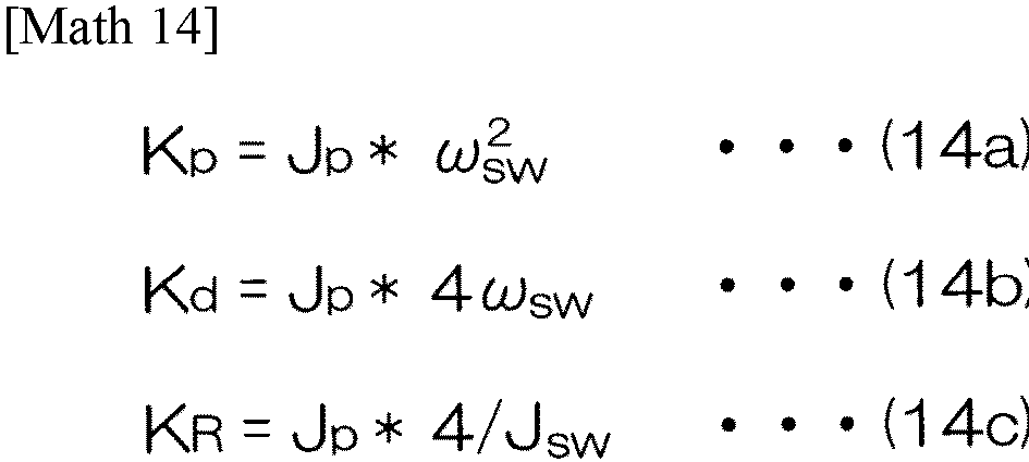

- In the two-
inertia model 302 inFIG. 14 , when the proportional gain Kp, the differential gain Kd and the vibration suppression gain KR are respectively set as in the above Expressions (14a), (14b), and (14c), the column angle θρ and the wheel angle θsw both exhibit critical damping (ζ = 1), and vibration can be suppressed. However, in the two-inertia model 302 ofFIG. 14 , the resonant frequency is fixed at ωsw. In other words, in the conventional example, the resonant frequency and damping characteristics cannot be set optionally. - Next, an electric power steering system to which a motor control device according to a second embodiment of the present invention is applied (hereinafter, referred to as "electric power steering system according to second embodiment") will be described.
- In the electric power steering system according to the second embodiment, a configuration of a
motor control ECU 202A is different from the configuration of themotor control ECU 202 inFIG. 2 . In the electric power steering system according to the second embodiment, the automatic steering command value θadac and the mode setting signals S1, S2, S3 are not given from the host ECU 201 (seeFIG. 1 ) to themotor control ECU 202A. -
FIG. 15 is a block diagram illustrating the configuration of themotor control ECU 202A used in the electric power steering system according to the second embodiment. - The
motor control ECU 202A includes amicrocomputer 50A, the drive circuit (inverter circuit) 41 that is controlled by themicrocomputer 50A and that supplies electric power to theelectric motor 18, and thecurrent detection circuit 42 that detects a current flowing through the electric motor 18 (hereinafter referred to as "motor current I"). - The
microcomputer 50A includes a CPU and memory (such as ROM, RAM, non-volatile memory, and so forth), and functions as a plurality of functional processing units by executing a predetermined program. The plurality of functional processing units include an assist torque commandvalue setting unit 151, a first reductionratio multiplication unit 152, a firsttorque computation unit 153, a secondtorque computation unit 154, a firsttorque addition unit 155, a disturbancetorque estimation unit 156, a secondtorque addition unit 157, a first reductionratio division unit 158, atorque control unit 159, a second reductionratio multiplication unit 160, a rotationalangle computation unit 161, and a second reductionratio division unit 162. - The second reduction
ratio multiplication unit 160 multiplies the motor torque command value Tm computed by the first reductionratio division unit 158 by the reduction ratio N of thespeed reducer 19, to convert the motor torque command value Tm into the output shaft torque command value N·Tm that acts on theoutput shaft 9. - The rotational
angle computation unit 161 computes the rotor rotational angle θm of theelectric motor 18 based on the output signal from therotational angle sensor 23. The second reductionratio division unit 162 converts the rotor rotational angle θm computed by the rotationalangle computation unit 161 into the rotational angle (actual steering angle) θ of theoutput shaft 9 by dividing the rotor rotational angle θm by the speed reduction ratio N. - The assist torque command
value setting unit 151 sets the assist torque command value Tas that is a target value of the assist torque necessary for manual operations. Actions of the assist torque commandvalue setting unit 151 are similar to those of the assist torque commandvalue setting unit 51 inFIG. 2 , and accordingly detailed description thereof will be omitted. - The first reduction
ratio multiplication unit 152 multiplies the assist torque command value Tas set by the assist torque commandvalue setting unit 151 by the reduction ratio N, to convert the assist torque command value Tas for theelectric motor 18 into an assist torque command value N·Tas for theoutput shaft 9. The assist torque command value Tas is given to the secondtorque addition unit 157. - The first
torque computation unit 153 includes adifferential computation unit 153A and a firstgain multiplication unit 153B. Thedifferential computation unit 153A computes the time differential value dTtb/dt of the steering torque Ttb. The firstgain multiplication unit 153B computes a first torque Gd·dTtb/dt by multiplying the differential value dTtb/dt computed by thedifferential computation unit 153A by the first gain Gd. - The second
torque computation unit 154 computes a second torque Gp·Ttb by multiplying the steering torque Ttb by the second gain Gp. - The first
torque addition unit 155 adds the first torque Gd·dTtb/dt and the second torque Gp·Ttb to compute the resonance control torque Tres (= Gd·dTtb/dt + Gp·Ttb). The resonance control torque Tres is given to the secondtorque addition unit 157. - A disturbance
torque estimation unit 156 estimates the disturbance torque (disturbance load) Tlc, the steering angle θ, and the steering angle differential value (angular velocity) dθ/dt, based on the output shaft torque command value N·Tm and the actual steering angle θ. The estimated values of the disturbance torque Tlc, the steering angle θ, and the steering angle differential value (angular velocity) dθ/dt are represented by ^Tlc, ^θ, and d^θ/dt, respectively. The configuration and actions of the disturbancetorque estimation unit 156 are similar to those of the disturbancetorque estimation unit 66 inFIG. 5 , and accordingly detailed description thereof will be omitted. - The disturbance torque estimation value ^Tlc computed by the disturbance
torque estimation unit 156 is given to the secondtorque addition unit 157 as a disturbance torque compensation value. - The second
torque addition unit 157 computes the output shaft torque command value N·Tm (= N·Tas + Gd·dTtb/dt + Gp·Ttb - ^Tlc) by subtracting the disturbance torque estimation value ^Tlc from a value obtained by adding the resonance control torque Tres to the assist torque command value N·Tas. - The output shaft torque command value N·Tm is given to the first reduction
ratio division unit 158. The first reductionratio division unit 158 computes the motor torque command value Tm by dividing the output shaft torque command value N·Tm by the reduction ratio N. This motor torque command value Tm is given to thetorque control unit 159. - The
torque control unit 159 drives thedrive circuit 41 such that the motor torque of theelectric motor 18 is brought closer the motor torque command value Tm. The configuration and actions of thetorque control unit 159 are similar to those of thetorque control unit 55 inFIG. 2 , and accordingly detailed description thereof will be omitted. -
FIG. 16 is a schematic diagram illustrating a two-inertia model 303 corresponding to the electric power steering system including themotor control ECU 202A illustrated inFIG. 15 . - In this two-
inertia model 303, driver torque Td is applied to thesteering wheel 2 by the driver, and also -Ttb, which is the sign-inverted value of the steering torque Ttb, is applied from thetorsion bar 10. Driving torque N·Tm equivalent to the output shaft torque command value N·Tm is applied from theelectric motor 18 to thesteering column 310. Note that N·Tm = (N·Tas + Gd·dTtb/dt + Gp·Ttb) holds. - In the two-
inertia model 303 inFIG. 16 , the equation of motion on the steering column side is expressed by the following Expression (16a), and the equation of motion on the steering wheel side is expressed by the following Expression (16b).
- In the two-
inertia model 303 inFIG. 16 , when the second gain Gp and the first gain Gd, are respectively set to values such as in the following Expressions (17a) and (17b), for example, a transfer function G (N·Tm → θp) from the driving torque N·Tm to the column angle θp is expressed by the following Expression (18a), and a transfer function G (N·Tm → θsw) from the driving torque N·Tm to the wheel angle θsw is expressed by the following Expression (18b).

- In the two-
inertia model 303 ofFIG. 16 , i.e., in the present modification, when the second gain Gp and the first gain Gd are respectively set as in the above Expressions (17a) and (17b), for example, the resonant frequency ω and the damping ratio ζ can be optionally set. - In the second embodiment, the resonant frequency ω and damping characteristics can be optionally set, and accordingly the responsivity can be changed. Specifically, the greater a value the resonant frequency ω is set to, the faster the responsivity becomes.
- In the second embodiment, load compensation is performed, but load compensation does not necessarily have to be performed. In this case, the second
torque addition unit 157 computes the output shaft torque command value N·Tm (= N·Tas + Gd·dTtb/dt + Gp·Ttb) by adding the resonance control torque Tres to the assist torque command value N·Tas. - When there is no load compensation, the steering torque Ttb is conceivably being fed back to the
steering column 310 in advance, and accordingly with the second gain when there is no load compensation as Gp', and with the second gain when there is load compensation as Gp, Gp' = (Gp - 1) is set. - Next, an electric power steering system to which a motor control device according to a third embodiment of the present invention is applied (hereinafter, referred to as "electric power steering system according to third embodiment") will be described.
- The electric power steering system according to the third embodiment has the same overall configuration as that illustrated in
FIG. 1 . In the electric power steering system according to the third embodiment, the configuration of themotor control ECU 202 is similar to the configuration of themotor control ECU 202 inFIG. 2 , but the configuration of theangle control unit 54 in themotor control ECU 202 inFIG. 2 is different. Theconfigurations 51 to 53 and 55 to 59 inFIG. 2 , other than theangle control unit 54, are the same in the electric power steering system according to the third embodiment. -
FIG. 17 is a block diagram illustrating a configuration of anangle control unit 54A used in themotor control ECU 202 in the electric power steering system according to the third embodiment. InFIG. 17 , portions corresponding to those inFIG. 5 described above are denoted by the same signs as those inFIG. 5 . - The
angle control unit 54A inFIG. 17 computes an integrated motor torque command value Tmint based on the integrated angle command value θsint, the steering torque Ttb, and the output signal of therotational angle sensor 23. Theangle control unit 54A inFIG. 17 differs in comparison with theangle control unit 54 inFIG. 5 in that the low-pass filter (LPF) 61 inFIG. 5 is not provided, and that a configuration of afeedback control unit 400 is different from the configuration of thefeedback control unit 62 inFIG. 5 . - The actions of the first
torque computation unit 63, the secondtorque computation unit 64, the firsttorque addition unit 65, the disturbancetorque estimation unit 66, the first reductionratio division unit 68, the reductionratio multiplication unit 69, the rotationalangle computation unit 70, and the second reductionratio division unit 71 inFIG. 17 are the same as the actions of the corresponding units inFIG. 5 , and accordingly description thereof will be omitted. - The
feedback control unit 400 includes a targettorque computation unit 401, a feedbacktorque computation unit 402, and a torquedeviation computation unit 403. - The target
torque computation unit 401 computes a target torque Tta by performing predetermined computation on the integrated angle command value θsint computed by the integrated angle command value computation unit 53 (seeFIG. 2 ). - The target
torque computation unit 401 includes a proportionalgain multiplication unit 411, a first-orderdifferential computation unit 412, a first-order differentialgain multiplication unit 413, a second-orderdifferential computation unit 414, a second-order differentialgain multiplication unit 415, a third-orderdifferential computation unit 416, a third-order differentialgain multiplication unit 417, a fourth-orderdifferential computation unit 418, a fourth-order differentialgain multiplication unit 419, and first tofourth addition units 420 to 423. - The proportional
gain multiplication unit 411 multiplies the integrated angle command value θsint by a proportional gain K0dot. - The first-order
differential computation unit 412 computes a first-order differential value dθsint/dt of the integrated angle command value θsint. The first-order differentialgain multiplication unit 413 multiplies the first-order differential value dθsint/dt computed by the first-orderdifferential computation unit 412 by a first-order differential gain K1dot. - The second-order
differential computation unit 414 computes a second-order differential value d2θsint/dt2 of the integrated angle command value θsint. The second-order differentialgain multiplication unit 415 multiplies the second-order differential value d2θsint/dt2 computed by the second-orderdifferential computation unit 414 by a second-order differential gain K2dot. - The third-order
differential computation unit 416 computes a third-order differential value d3θsint/dt3 of the integrated angle command value θsint. The third-order differentialgain multiplication unit 417 multiplies the third-order differential value d3θsint/dt3 computed by the third-orderdifferential computation unit 416 by a third-order differential gain K3dot. - The fourth-order
differential computation unit 418 computes a fourth-order differential value d4θsint/dt4 of the integrated angle command value θsint. The fourth-order differentialgain multiplication unit 419 multiplies the fourth-order differential value d4θsint/dt4 computed by the fourth-orderdifferential computation unit 418 by a fourth-order differential gain K4dot. - The
first addition unit 420 adds a multiplication result K4dot·d4θsint/dt4 of the fourth-order differentialgain multiplication unit 419 and a multiplication result K3dot·d3θsint/dt3 of the third-order differentialgain multiplication unit 417. - The
second addition unit 421 adds the addition result of the first addition unit 420 (K3dot·d3θsint/dt3 + K4dot·d4 θsint/dt4) and the multiplication result K2dot·d2θsint/dt2 of the second-order differentialgain multiplication unit 415. - The
third addition unit 422 adds the addition result of the second addition unit 421 (K2dot·d2θsint/dt2 + K3dot·d3θsint/dt3 + K4dot·d4θsint/dt4) and the multiplication result K1dot·dθsint/dt of the first-order differentialgain multiplication unit 413. - The
fourth addition unit 423 adds the addition result of the third addition unit 422 (K1dot·θsint/dt + K2dot·d2θsint/dt2 + K3dot·d3θsint/dt3 + K4dot·d4θsint/dt4) and the multiplication result K0dot·θsint of the proportionalgain multiplication unit 411, thereby computing the target torque Tta. The target torque Tta is expressed as (K0dot·θsint + (K1dot·θsint/dt + K2dot·d2θsint/dt2+ K3dot·d3θsint/dt3 + K4dot·d4θsint/dt4). - The feedback
torque computation unit 402 computes feedback torque Tfe by performing predetermined computation with respect to the actual steering angle θ. - The feedback
torque computation unit 402 includes a proportionalgain multiplication unit 431, adifferential computation unit 432, a differentialgain multiplication unit 433, and anaddition unit 434. The proportionalgain multiplication unit 431 multiplies the actual steering angle θ computed by the second reductionratio division unit 71 by the proportional gain Kp. - The
differential computation unit 432 computes a time differential value dθ/dt of the actual steering angle θ. The differentialgain multiplication unit 433 multiplies the differential value dθ/dt computed by thedifferential computation unit 432 by the differential gain Kd. Theaddition unit 434 adds the multiplication result Kp·θ of the proportionalgain multiplication unit 431 and the multiplication result dθ/dt of the differentialgain multiplication unit 433, thereby computing feedback control torque Tfe. The feedback torque Tfe is (Kp·θ + Kd·dθ/dt). - Note that in
FIG. 17 , the actual steering angle θ computed by the second reductionratio division unit 71 is input to the feedbacktorque computation unit 402. However, the steering angle estimation value ^θ computed by the disturbancetorque estimation unit 66 may be input to the feedbacktorque computation unit 402 instead of the actual steering angle θ. In this case, the feedback torque Tfe is (Kp·^θ + Kd·d^θ/dt). - The torque
deviation computation unit 403 computes the feedback control torque Tfb by subtracting the feedback torque Tfe from the target torque Tta. The feedback control torque Tfb is a control torque for bringing the actual steering angle θ closer to the integrated angle command value θsint. In this embodiment, the feedback control torque Tfb is an example of "basic torque command value" according to the present invention. - The second
torque addition unit 67 subtracts the disturbance torque estimation value ^Tlc from a value obtained by adding the resonance control torque Tres to the feedback control torque (basic torque command value) Ttb, thereby computing an integrated steering torque command value Tsint (= Tfb + Gd·dTtb/dt + Gp·Ttb - ^Tlc). - The integrated steering torque command value Tsint is given to the first reduction
ratio division unit 68. The first reductionratio division unit 68 computes the integrated motor torque command value Tmint by dividing the integrated steering torque command value Tsint by the reduction ratio N. This integrated motor torque command value Tmint is given to the second weighting unit 57 (seeFIG. 2 ). -
FIG. 18 is a schematic diagram illustrating a two-inertia model 304 corresponding to the electric power steering system according to the third embodiment in automatic steering mode or in cooperative steering mode. - In this two-
inertia model 304, the driver torque Td is applied to thesteering wheel 2 by the driver, and also -Ttb, which is the sign-inverted value of the steering torque Ttb, is applied from thetorsion bar 10. The driving torque N·Tm is applied to thesteering column 310 from theelectric motor 18. The driving torque N·Tm is N·Tm = (K0dot·θsint + K1dot·dθsint/dt + K2dot·d2θsint/d2 + K3dot·d3θsint/dt3 + K4dot·d4θsint/dt4 - Kp·θp - dθp/dt + Gp·Ttb + Gd·dTtb/dt). - Note that when load compensation is not performed, the steering torque Ttb and the road load torque Trl are applied to the
steering column 310 in addition to the driving torque N·Tm. -
FIG. 19 is a control block diagram of a feedback control system of the electric power steering system according to the third embodiment in automatic steering mode or in cooperative steering mode, and is a block diagram representing a model of the column and the steering wheel that are objects of control. Here,FIG. 19 is a block diagram corresponding toFIG. 18 and Expressions (19a) and (19b) described later. - The feedback torque Tfe computed by the feedback
torque computation unit 402 based on the first column angle θp (actual steering angle θ), is subtracted from the target torque Tta computed by the targettorque computation unit 401 based on the integrated angle command value θsint, thereby generating the feedback control torque Tfb (= Tta - Tfe). Note that in the present embodiment, the proportional gain Kp and the differential gain Kd each include the column inertia Jp, which will be described later. Also, when the proportional gain K0dot, the first-order differential gain K1dot, the second-order differential gain K2dot, the third-order differential gain K3dot, and the fourth-order differential gain K4dot are set to significant values other than zero, column inertia Jp is included. - The resonance control torque Tres (= Gd·dTtb/dt + Gp·Ttb) is added to the feedback control torque Ttb. This added value (Tfb + Gd·dTtb/dt + Gp·Ttb) is equivalent to the output shaft torque command value N·Tm corresponding to a value obtained by multiplying the angular acceleration of the column angle θρ (hereinafter referred to as column angular acceleration d2θp/dt2) by the column inertia Jp. A driving torque corresponding to this output shaft torque command value N·Tm is applied from the
electric motor 18 to thesteering column 310. When the driving torque N·Tm is input to thesteering column 310 having inertia that is Jp, thesteering column 310 rotates, and of the rotational angle (column angle θp) is measured based on therotational angle sensor 23, and feedback thereof is performed. - Here, the steering torque Ttb is equivalent to a value obtained by multiplying difference between the column angle θρ and the wheel angle θsw (θsw - θp) by the torsion bar stiffness ktb, and Ttb = ktb (θsw - θp) holds. The sum of a value Gd·dTtb/dt obtained by multiplying the differential value of this steering torque Ttb by the first gain Gd, and a value Gp·Ttb obtained by multiplying this steering torque Ttb by the second gain Gp, is fed back as resonance control torque Tres. Also, when the steering torque Ttb and the driver torque Td are input to the
steering wheel 2, having inertia that is Jsw, thesteering wheel 2 rotates thereby. - In the two-
inertia model 304 inFIG. 18 , the equation of motion on the steering column side is expressed by the following Expression (19a), and the equation of motion on the steering wheel side is expressed by the following Expression (19b).
- In the two-
inertia model 304 ofFIG. 18 , when the proportional gain Kp, the differential gain Kd, the second gain Gp, and the first gain Gd are respectively set to values such as those shown in the above Expressions (11a), (a11), (11c) and (11d), for example, the transfer function G(θsint → θp) from the integrated angle command value θsint to the column angle θρ is expressed by the following Expression (20a), and the transfer function G(θsint → θsw) from the integrated angle command value θsint to the wheel angle θsw is expressed by the following Expression (20b).
- When the proportional gain K0dot, the first-order differential gain K1dot, the second-order differential gain K2dot, the third-order differential gain K3dot, and the fourth-order differential gain K4dot are set to values as in the following Expression (21), for example, the configuration of the
feedback control unit 400 inFIG. 17 becomes equivalent to thefeedback control unit 62 inFIG. 5 . However, the angle command value θsint input to thefeedback control unit 400 inFIG. 17 is different from the angle command value θsin input to thefeedback control unit 62 inFIG. 5 .
[Math 21]
- In this case, the gain Kp for the angle θsint (θsin in
FIG. 5 ) and the gain Kd for the angular velocity dθsint/dt (dθsin/dt inFIG. 5 ) on the command value side are the same as the gain Kp for the angle θ and the gain Kd for the angular velocity dθ/dt on the feedback side, respectively. That is to say, a common gain is set on the command value side and the feedback side. - In the third embodiment, different gains can be set on the command value side and the feedback side. In the third embodiment, different gains are preferably set on the command value side and the feedback side. In other words, it is preferable that the gain used in the computation of the target torque Tta and the gain used in the computation of the feedback torque Tfe are different from each other.
- A specific example of setting the proportional gain K0dot, the first-order differential gain K1dot, the second-order differential gain K2dot, the third-order differential gain K3dot, and the fourth-order differential gain K4dot will be described below. Note that the proportional gain Kp, the differential gain Kd, the second gain Gp, and the first gain Gd are assumed to be set to the values in the above Expressions (11a), (11b), (11c) and (11d).
- In a first setting example, the proportional gain K0dot, the first-order differential gain K1dot, the second-order differential gain K2dot, the third-order differential gain K3dot, and the fourth-order differential gain K4dot are set to values as in the following Expression (22).
[Math 22]
- In this case, the transfer function G(θsint → θp) from the integrated angle command value θsint to the column angle θp is expressed by the following Expression (23a), and the transfer function G(θsint → θsw) from the integrated angle command value θsint to the wheel angle θsw is expressed by the following Expression (23b).

- In this case, the wheel angle θsw responds with a fourth-order lag. In this case, the resonant frequency ω and the damping ratio ζ can be optionally set, in the same way as in the first embodiment.
- In a second setting example, the proportional gain K0dot, the first-order differential gain K1dot, the second-order differential gain K2dot, the third-order differential gain K3dot, and the fourth-order differential gain K4dot are set to values as in the following Expression (24).
[Math 24]
- In this case, the transfer function G(θsint → θp) from the integrated angle command value θsint to the column angle θρ is expressed by the following Expression (25a), and the transfer function G(θsint → θsw) from the integrated angle command value θsint to the wheel angle θsw is expressed by the following Expression (25b).

- In this case, the wheel angle θsw responds with a third-order lag. In this case, the resonant frequency ω can be optionally set, in the same way as in the first embodiment.
- In a third setting example, the proportional gain K0dot, the first-order differential gain K1dot, the second-order differential gain K2dot, the third-order differential gain K3dot, and the fourth-order differential gain K4dot are set as in the following Expression (26).
[Math 26]
- In this case, the transfer function G(θsint → θp) from the integrated angle command value θsint to the column angle θρ is expressed by the following Expression (27a), and the transfer function G(θsint → θsw) from the integrated angle command value θsint to the wheel angle θsw is expressed by the following Expression (27b).

- In this case, the wheel angle θsw responds with a second-order lag. In the third setting example, the resonant frequency ω and the damping ratio ζ can be optionally set, in the same way as in the first embodiment.
- In a fourth setting example, the proportional gain K0dot, the first-order differential gain K1dot, the second-order differential gain K2dot, the third-order differential gain K3dot, and the fourth-order differential gain K4dot are set as in the following Expression (28).
[Math 28]
- In this case, the transfer function G(θsint → θp) from the integrated angle command value θsint to the column angle θρ is expressed by the following Expression (29a), and the transfer function G(θsint → θsw) from the integrated angle command value θsint to the wheel angle θsw is expressed by the following Expression (29b).

- In this case, the wheel angle θsw responds with a first-order lag. In this case, the resonant frequency ω can be optionally set, in the same way as in the first embodiment.
- Note that in this case, a low-pass filter (LPF) of first or higher order, having a cutoff frequency no higher than ω, is preferably provided between the integrated angle command value computation unit 53 (see
FIG. 2 ) and theangle control unit 54A (seeFIG. 17 ). - In a fifth setting example, the proportional gain K0dot, the first-order differential gain K1dot, the second-order differential gain K2dot, the third-order differential gain K3dot, and the fourth-order differential gain K4dot are set as in the following Expression (30).
[Math 30]
- In this case, the transfer function G(θsint → θp) from the integrated angle command value θsint to the column angle θρ is expressed by the following Expression (31a), and the transfer function G(θsint → θsw) from the integrated angle command value θsint to the wheel angle θsw is expressed by the following Expression (31b).

- In this case, the wheel angle θsw responds without lag.
- Note that in this case, a low-pass filter (LPF) of second or higher order, having a cutoff frequency no higher than ω, is preferably provided between the integrated angle command value computation unit 53 (see
FIG. 2 ) and theangle control unit 54A (seeFIG. 17 ). - In the third embodiment, load compensation is performed, but load compensation does not necessarily have to be performed. In this case, a value (Tfb + Gd • dTtb/dt + Gp·Ttb), obtained by adding the resonance control torque Tres (= Gd·dTtb/dt + Gp·Ttb) to the feedback control torque (basic torque command value) Tfb becomes the integrated steering torque command value Tsint.
- When there is no load compensation, the steering torque Ttb is conceivably being fed back to the
steering column 310 in advance, and accordingly with the second gain when there is no load compensation as Gp', and with the second gain when there is load compensation as Gp, Gp' = (Gp - 1) is set. - In the third embodiment, setting the proportional gain Kp, the derivative gain Kd, the second gain Gp, the first gain Gd, the proportional gain K0dot, the first-order differential gain K1dot, the second-order differential gain K2dot, the third-order differential gain K3dot, and the fourth-order differential gain K4dot, to the respective values such as described above, enables response characteristics (such as n-th order lag and so forth) to be optionally set, in addition to the resonant frequency ω and the damping ratio ζ.
- Also, in the third embodiment, switching can be performed among the cooperative steering mode in which the
electric motor 18 can be controlled based on the integrated angle command value θsint, the manual steering mode in which theelectric motor 18 can be controlled based only on the assist torque command value Tas, and the automatic steering mode in which theelectric motor 18 can be controlled based only on the automatic steering command value θadac. - That is to say, in the electric power steering system that can control the
electric motor 18 based on the integrated angle command value θsint, theelectric motor 18 can be controlled based only on the assist torque command value Tas. - While the first embodiment, the second embodiment, and the third embodiment of this invention have been described above, this invention can also be carried out in yet other forms.
- For example, in the first embodiment, the second embodiment, and the third embodiment, a dead band processing unit may be provided for at least one of the steering torque Ttb input to the first
torque computation units torque computation units - A case will be described below, with reference to
FIG. 20 ,FIG. 23 andFIG. 24 , in which the dead band processing unit is provided for at least one of the steering torque Ttb input to the first torque computation unit 63 (seeFIG. 5 andFIG. 17 ) and the steering torque Ttb input to the second torque computation unit 64 (seeFIG. 5 andFIG. 17 ) in the first embodiment (third embodiment). InFIG. 20 ,FIG. 23 , andFIG. 24 , only the parts of the configurations of theangle control units -
FIG. 20 is a block diagram illustrating an example in which a deadband processing unit 501 is provided upstream of the secondtorque computation unit 64. - The steering torque Ttb is input to the dead
band processing unit 501.FIG. 21 shows an example of input/output characteristics of the deadband processing unit 501. - With a dead band width of W, the dead
band processing unit 501 outputs zero as a steering torque Ttb,de following dead band processing in a case in which the steering torque Ttb is within a range of -W/2 or greater and W/2 or smaller (dead band region). - In a region in which the steering torque Ttb is smaller than -W/2, the dead
band processing unit 501 outputs [Ttb + (W/2)] as the steering torque Ttb,de following the dead band processing. In a region in which the steering torque Ttb is greater than W/2, the deadband processing unit 501 outputs [Ttb - (W/2)] as the steering torque Ttb,de following the dead band processing. The dead band width W is set in advance. - In this case, the second
torque computation unit 64 computes second torque Gp·Ttb,de by multiplying the steering torque Ttb,de following the dead band processing by the second gain Gp. Accordingly, in this case, the resonance control torque Tress is Gd·dTtb/dt + Gp·Ttb,de. - Note that within a dead band region in which the absolute value of the steering torque Ttb is small, the dead
band processing unit 501 may output a value close to zero as the steering torque Ttb,de following the dead band processing. For example, the input/output characteristics of the deadband processing unit 501 may be characteristics such as shown inFIG. 22 . - In other words, the input/output characteristics of the dead
band processing unit 501 may be characteristics such that, within a dead band region (a range of -W/2 or greater and W/2 or smaller) in which the absolute value of the steering torque Ttb is small, the absolute value of the steering torque Ttb,de following the dead band processing gradually increases quadratically as the absolute value of the steering torque Ttb increases, and, in a range in which the absolute value of the steering torque Ttb is greater than the dead band region, the absolute value of the steering torque Ttb,de following the dead band processing increases linearly as the absolute value of the steering torque Ttb increases. - The dead
band processing unit 501 may be provided upstream of both the firsttorque computation unit 63 and the secondtorque computation unit 64, as illustrated inFIG. 23 . - In this case, the first
torque computation unit 63 computes the first torque Gd·dTtb,de/dt by multiplying the time differential value dTtb,de/dt of the steering torque Ttb,de following the dead band processing by the first gain Gd. The secondtorque computation unit 64 computes the second torque by multiplying the steering torque Ttb,de following the dead band processing by the second gain Gp. Accordingly, in this case, the resonance control torque Tress is Gd·dTtb,de/dt + Gp·Ttb,de. - The dead
band processing unit 501 may be provided upstream of the firsttorque computation unit 63, as illustrated inFIG. 24 . - In this case, the first
torque computation unit 63 computes the first torque Gd·dTtb,de/dt by multiplying the time differential value dTtb,de/dt of the steering torque Ttb,de following the dead band processing by the first gain Gd. Accordingly, in this case, the resonance control torque Tress is Gd·dTtb,de/dt + Gp·Ttb. - The reason for providing the dead
band processing unit 501 will be described. The steering torque Ttb (primarily the sum of the driver torque Td applied to thesteering wheel 2 by the driver and the force generated by steering inertia) may be offset by friction and so forth. Accordingly, even when the absolute value of the actual steering torque Ttb is zero or close to zero, the absolute value of the steering torque Ttb that is detected by thetorque sensor 12 may be greater than the absolute value of the actual steering torque Ttb. Hence, when the absolute value of the actual steering torque Ttb is zero or close to zero, a resonance control torque Tres (= Gd·dTtb/dt + Gp·Ttb) that is greater than anticipated will be output, resulting in deviation (steering angle deviation) from the steering angle command value (integrated angle command value θsint). - As illustrated in
FIG. 20 ,FIG. 23 andFIG. 24 , when the deadband processing unit 501 is provided to at least one of the steering torque Ttb input to the firsttorque computation unit 63 and the secondtorque computation unit 64, the following effects can be obtained. That is to say, in a range in which the resonance of thesteering wheel 2 is great (a range in which the absolute value of the steering torque Ttb is great), resonance control based on the resonance control torque Tres can be performed. On the other hand, in a range in which the resonance of thesteering wheel 2 is small and resonance control is not necessary (a range in which the absolute value of the steering torque Ttb is small), steering angle deviation based on offset of the steering torque Ttb can be suppressed. - Although omitted from illustration, the dead
band processing unit 501 described above may be provided only upstream from the second torque computation unit 154 (FIG. 15 ) of the second embodiment, or the deadband processing unit 501 described above may be provided only upstream from the first torque computation unit 153 (FIG. 15 ) of the second embodiment. Also, the deadband processing unit 501 described above may be provided upstream from both the first torque computation unit 153 (FIG. 15 ) and the second torque computation unit 154 (FIG. 15 ) of the second embodiment. - In the above first, second, and third embodiments, the
first weighting unit 56, thesecond weighting unit 57, and thethird weighting unit 58 are provided, but thethird weighting unit 58 may be omitted. In this case, two types of steering modes, i.e., the manual steering mode and the cooperative steering mode, will be available. - In the first, second and third embodiments described above, assumption is made that the steering torque (torsion bar torque) Ttb is expressed as Ttb = ktb (θsw - θp), and this Ttb is fed back, but, as can be understood from the expression Ttb = ktb (θsw - θp), this is equivalent to feeding back the relative angle between the
steering wheel 2 and thesteering column 310. Accordingly, providing an angle sensor for detecting the rotational angle of thesteering wheel 2 enables similar control without using the steering torque Ttb by feedback of the relative angle between thesteering wheel 2 and thesteering column 310 and the relative speed between thesteering wheel 2 and the steering column 310 (which may be detected by a speed sensor or may be the differential value of the relative angle). - In this case, the resonance control torque Tres is expressed as Tres = [{Gp' x (relative angle)} + {Gd' x (relative speed)}]. Here, Gp' = Gp·ktb, and Gd' = Gd·ktb hold.
- Although embodiments of the present invention are described in detail above, these are merely specific examples used to clarify the technical content of the present invention, and the present invention should not be construed as being limited to these specific examples, and the scope of the present invention is limited only by the appended claims.
- This application corresponds to
Japanese Patent Application No. 2022-6684 filed with the Japan Patent Office on January 19, 2022 -
- 1 Electric power steering system
- 3 Steered wheels
- 4 Steering operation mechanism
- 18 Electric motor
- 51, 151 Assist torque command value setting unit
- 52 Manual steering command value generation unit
- 53 Integrated angle command value computation unit
- 54 Angle control unit
- 55 Torque control unit
- 59 Addition unit
- 61 Low-pass filter
- 62, 400 Feedback control unit
- 63, 153 First torque computation unit
- 63A, 153A Differential computation unit
- 63B, 153B First gain multiplication unit
- 64, 154 Second torque computation unit
- 65, 155 First torque addition unit
- 66, 156 Disturbance torque estimation unit
- 67, 157 Second torque addition unit
- 401 Target torque computation unit
- 402 Feedback torque computation unit
- 403 Torque deviation computation unit
- 501 Dead band processing unit
Claims (6)
- A motor control device that controls an electric motor that applies steering force to an output shaft linked to a steering wheel via a torsion bar, the motor control device comprising:a steering torque detection unit that detects a steering torque applied to the steering wheel; and
a motor torque command value setting unit that sets a motor torque command value that is a target value of motor torque of the electric motor, whereinthe motor torque command value setting unit includesa basic torque command value setting unit that sets a basic torque command value,a correction unit that corrects the basic torque command value set by the basic torque command value setting unit, using a resonance control torque, anda motor torque command value computation unit that computes the motor torque command value based on the basic torque command value following correction by the correction unit, andthe resonance control torque is set using a first torque obtained by multiplying a differential value of the steering torque by a predetermined first gain, and a second torque obtained by multiplying the steering torque by a predetermined second gain. - The motor control device according to claim 1, further comprising:
a rotational angle detection unit that detects a rotational angle of the electric motor, wherein the basic torque command value setting unit includesan angle deviation computation unit that computes a difference between a rotational angle command value that is a target value of a rotational angle of the output shaft and a rotational angle of the output shaft computed from the rotational angle detected by the rotational angle detection unit, anda basic torque command value computation unit that computes the basic torque command value by performing predetermined feedback computation with respect to angle deviation computed by the angle deviation computation unit. - The motor control device according to claim 1, further comprising:a rotational angle detection unit that detects a rotational angle of the electric motor, wherein the basic torque command value setting unit includesa target torque computation unit that computes a target torque based on a rotational angle command value that is a target value of a rotational angle of the output shaft,a feedback torque computation unit that computes a feedback torque based on the rotational angle detected by the rotational angle detection unit, anda basic torque command value computation unit that computes the basic torque command value by computing a deviation between the target torque and the feedback torque, anda gain used in the computation of the target torque and a gain used in the computation of the feedback torque are different from each other.
- The motor control device according to claim 2 or 3, further comprising:a manual steering command value computation unit that generates a manual steering command value; andan integrated angle command value computation unit that computes an integrated angle command value by adding the manual steering command value to an automatic steering angle command value, wherein the rotational angle command value is the integrated angle command value.
- The motor control device according to any one of claims 1 to 4, further comprising a disturbance torque estimation unit that estimates disturbance torque other than the motor torque of the electric motor acting on the output shaft, based on the motor torque command value or the motor torque generated by the electric motor, and a rotational angle of the output shaft, wherein the correction unit is configured to correct the basic torque command value by using the resonance control torque and the disturbance torque.
- The motor control device according to any one of claims 1 to 5, wherein a dead band is set for at least one of the steering torque that is an input value for computing the first torque, and the steering torque that is an input value for computing the second torque.
Applications Claiming Priority (2)
| Application Number | Priority Date | Filing Date | Title |
|---|---|---|---|
| JP2022006684 | 2022-01-19 | ||
| PCT/JP2022/015152 WO2023139808A1 (en) | 2022-01-19 | 2022-03-28 | Motor control device |
Publications (2)
| Publication Number | Publication Date |
|---|---|
| EP4468591A1 true EP4468591A1 (en) | 2024-11-27 |
| EP4468591A4 EP4468591A4 (en) | 2025-04-30 |
Family
ID=87348540
Family Applications (1)
| Application Number | Title | Priority Date | Filing Date |
|---|---|---|---|
| EP22921003.4A Pending EP4468591A4 (en) | 2022-01-19 | 2022-03-28 | ENGINE CONTROL DEVICE |
Country Status (5)
| Country | Link |
|---|---|
| US (1) | US20250083736A1 (en) |
| EP (1) | EP4468591A4 (en) |
| JP (1) | JP7818171B2 (en) |
| CN (1) | CN118633238A (en) |
| WO (1) | WO2023139808A1 (en) |
Family Cites Families (9)
| Publication number | Priority date | Publication date | Assignee | Title |
|---|---|---|---|---|
| JPS5576760A (en) * | 1978-12-06 | 1980-06-10 | Nippon Seiko Kk | Electric power steering device |
| JP2012183881A (en) * | 2011-03-04 | 2012-09-27 | Jtekt Corp | Electric power steering device |
| WO2014136515A1 (en) * | 2013-03-08 | 2014-09-12 | 日本精工株式会社 | Electric power steering device |
| JP7194326B2 (en) | 2017-04-13 | 2022-12-22 | 株式会社ジェイテクト | motor controller |
| US11685430B2 (en) * | 2018-05-21 | 2023-06-27 | Jtekt Corporation | Motor control device |
| JP7116888B2 (en) * | 2018-07-31 | 2022-08-12 | 株式会社ジェイテクト | motor controller |
| JP7256958B2 (en) * | 2019-05-27 | 2023-04-13 | 株式会社ジェイテクト | electric power steering device |
| JP2021154895A (en) * | 2020-03-27 | 2021-10-07 | 株式会社ジェイテクト | Steering control device |
| JP7212952B2 (en) | 2020-06-24 | 2023-01-26 | 株式会社サンセイアールアンドディ | game machine |
-
2022
- 2022-03-28 JP JP2023575041A patent/JP7818171B2/en active Active
- 2022-03-28 US US18/728,297 patent/US20250083736A1/en active Pending
- 2022-03-28 WO PCT/JP2022/015152 patent/WO2023139808A1/en not_active Ceased
- 2022-03-28 EP EP22921003.4A patent/EP4468591A4/en active Pending
- 2022-03-28 CN CN202280088886.2A patent/CN118633238A/en active Pending
Also Published As
| Publication number | Publication date |
|---|---|
| WO2023139808A1 (en) | 2023-07-27 |
| JP7818171B2 (en) | 2026-02-20 |
| JPWO2023139808A1 (en) | 2023-07-27 |
| CN118633238A (en) | 2024-09-10 |
| US20250083736A1 (en) | 2025-03-13 |
| EP4468591A4 (en) | 2025-04-30 |
Similar Documents
| Publication | Publication Date | Title |
|---|---|---|
| EP3798099B1 (en) | Motor control device | |
| EP3608203B1 (en) | Motor control apparatus | |
| EP3718859A1 (en) | Vehicle steering device | |
| EP3744611B1 (en) | Electric power steering system | |
| EP3572300A1 (en) | Motor control device | |
| EP4372980A1 (en) | Motor control device | |
| US12485964B2 (en) | Motor control device | |
| EP4470877A1 (en) | Motor control device | |
| EP4431368A1 (en) | Motor control device | |
| EP3939861B1 (en) | Steering device | |
| EP4417489A1 (en) | Motor control device | |
| US20250083736A1 (en) | Motor control device | |
| JP7681245B2 (en) | Steering gear | |
| JP2023069907A (en) | motor controller | |
| EP4734360A1 (en) | Motor control device | |
| EP4734353A1 (en) | Motor control device | |
| EP4729392A1 (en) | Motor control device | |
| EP4703240A1 (en) | Motor control device | |
| WO2024252630A1 (en) | Motor control device |
Legal Events
| Date | Code | Title | Description |
|---|---|---|---|
| STAA | Information on the status of an ep patent application or granted ep patent |
Free format text: STATUS: THE INTERNATIONAL PUBLICATION HAS BEEN MADE |
|
| PUAI | Public reference made under article 153(3) epc to a published international application that has entered the european phase |
Free format text: ORIGINAL CODE: 0009012 |
|
| STAA | Information on the status of an ep patent application or granted ep patent |
Free format text: STATUS: REQUEST FOR EXAMINATION WAS MADE |
|
| 17P | Request for examination filed |
Effective date: 20240806 |
|
| AK | Designated contracting states |
Kind code of ref document: A1 Designated state(s): AL AT BE BG CH CY CZ DE DK EE ES FI FR GB GR HR HU IE IS IT LI LT LU LV MC MK MT NL NO PL PT RO RS SE SI SK SM TR |
|
| DAV | Request for validation of the european patent (deleted) | ||
| DAX | Request for extension of the european patent (deleted) | ||
| A4 | Supplementary search report drawn up and despatched |
Effective date: 20250327 |
|
| RIC1 | Information provided on ipc code assigned before grant |
Ipc: H02P 21/20 20160101ALI20250324BHEP Ipc: H02P 21/05 20060101ALI20250324BHEP Ipc: H02P 6/10 20060101ALI20250324BHEP Ipc: H02P 23/12 20060101ALI20250324BHEP Ipc: B62D 6/00 20060101ALI20250324BHEP Ipc: B62D 5/04 20060101ALI20250324BHEP Ipc: H02P 23/04 20060101AFI20250324BHEP |