EP4468568A1 - Rotating electric machine - Google Patents
Rotating electric machine Download PDFInfo
- Publication number
- EP4468568A1 EP4468568A1 EP22921882.1A EP22921882A EP4468568A1 EP 4468568 A1 EP4468568 A1 EP 4468568A1 EP 22921882 A EP22921882 A EP 22921882A EP 4468568 A1 EP4468568 A1 EP 4468568A1
- Authority
- EP
- European Patent Office
- Prior art keywords
- stator coil
- stator
- coil
- crotch
- bent
- Prior art date
- Legal status (The legal status is an assumption and is not a legal conclusion. Google has not performed a legal analysis and makes no representation as to the accuracy of the status listed.)
- Pending
Links
Images


Classifications
-
- H—ELECTRICITY
- H02—GENERATION; CONVERSION OR DISTRIBUTION OF ELECTRIC POWER
- H02K—DYNAMO-ELECTRIC MACHINES
- H02K3/00—Details of windings
- H02K3/04—Windings characterised by the conductor shape, form or construction, e.g. with bar conductors
- H02K3/12—Windings characterised by the conductor shape, form or construction, e.g. with bar conductors arranged in slots
-
- H—ELECTRICITY
- H02—GENERATION; CONVERSION OR DISTRIBUTION OF ELECTRIC POWER
- H02K—DYNAMO-ELECTRIC MACHINES
- H02K3/00—Details of windings
- H02K3/04—Windings characterised by the conductor shape, form or construction, e.g. with bar conductors
- H02K3/28—Layout of windings or of connections between windings
-
- H—ELECTRICITY
- H02—GENERATION; CONVERSION OR DISTRIBUTION OF ELECTRIC POWER
- H02K—DYNAMO-ELECTRIC MACHINES
- H02K15/00—Processes or apparatus specially adapted for manufacturing, assembling, maintaining or repairing of dynamo-electric machines
- H02K15/06—Embedding prefabricated windings in the machines
- H02K15/062—Windings in slots; Salient pole windings
- H02K15/064—Windings consisting of separate segments
- H02K15/0643—Hairpin windings
-
- H—ELECTRICITY
- H02—GENERATION; CONVERSION OR DISTRIBUTION OF ELECTRIC POWER
- H02K—DYNAMO-ELECTRIC MACHINES
- H02K2213/00—Specific aspects, not otherwise provided for and not covered by codes H02K2201/00 - H02K2211/00
- H02K2213/03—Machines characterised by numerical values, ranges, mathematical expressions or similar information
-
- Y—GENERAL TAGGING OF NEW TECHNOLOGICAL DEVELOPMENTS; GENERAL TAGGING OF CROSS-SECTIONAL TECHNOLOGIES SPANNING OVER SEVERAL SECTIONS OF THE IPC; TECHNICAL SUBJECTS COVERED BY FORMER USPC CROSS-REFERENCE ART COLLECTIONS [XRACs] AND DIGESTS
- Y02—TECHNOLOGIES OR APPLICATIONS FOR MITIGATION OR ADAPTATION AGAINST CLIMATE CHANGE
- Y02T—CLIMATE CHANGE MITIGATION TECHNOLOGIES RELATED TO TRANSPORTATION
- Y02T10/00—Road transport of goods or passengers
- Y02T10/60—Other road transportation technologies with climate change mitigation effect
- Y02T10/64—Electric machine technologies in electromobility
Definitions
- the present invention relates to a rotary electric machine.
- the coil In a process of inserting a coil into a stator core in a production process of a rotary electric machine, the coil is inserted into the stator core by directly pressing the coil toward the stator core using an insertion jig.
- this has a structure in which the coil with the large crotch and the coil with the small crotch are inserted at positions overlapping in an axial direction, it is not possible to directly press all the coils from a predetermined direction. Therefore, the coil that is not able to be completely inserted is adjusted by being pressed from an oblique direction or the like, but this adjustment may cause a defect when the coil is inserted.
- PTL 1 discloses a configuration in which top portions 63A and 63B do not overlap and are displaced in the radial direction in turn portions 62A and 62B of the coil.
- an object of the present invention is to provide a coil of a rotary electric machine in which a height of a coil end is suppressed and a defect rate during assembly is improved.
- a rotary electric machine includes a stator core provided with a plurality of slots; and a plurality of stator coils arranged side by side in a radial direction of the stator core and arranged in the plurality of slots, in which the stator coil includes two linear portions that penetrate through the slots different from each other in layers different from each other in the axial direction of the stator core, and a turn portion that connects the two linear portions, the turn portion includes a top portion which is at a position farthest from the stator core in the axial direction, two inclined portions that connect the top portion and the linear portion, and a bent portion that is bent outward in the radial direction, the stator coil includes a first stator coil and a second stator coil that overlap each other in the axial direction, bent portions of the first stator coil and the second stator coil are at different positions in a circumferential direction, the bent portion of the first stator coil is formed at the inclined portion of the first stator coil, the bent portion of the second stator
- Positions, sizes, shapes, ranges, and the like of components illustrated in the drawings may not represent actual positions, actual sizes, actual shapes, actual ranges, and the like in order to facilitate understanding of the invention. Therefore, the present invention is not necessarily limited to the positions, the sizes, the shapes, the ranges, and the like disclosed in the drawings.
- the small-crotch stator coil 1d overlaps the large-crotch stator coil 1c when being inserted into the stator core 2.
- the small-crotch stator coil 1d cannot be seen from a predetermined direction (direction from the top to the bottom in FIG. 2(a) , direction from the front to the back in FIG. 2(b) ).
- the small-crotch stator coil 1d is hardly pressed by the insertion jig that pushes and inserts the coil into the stator core 2. Therefore, there is a problem that the height of the coil varies after insertion, and a defect occurs in the production process.
- the coil that cannot be pressed by the insertion jig in the related art is pressed not in an axial direction but in an oblique direction or the like for adjustment to suppress variations in the height of the coil.
- a slot liner (not illustrated) wound around each stator coil 1A is dragged to a slot wall surface of the stator core 2, and thus the position of the slot liner may be displaced or broken, which causes a defect.
- FIG. 3 A configuration of the stator coil 1 according to an embodiment of the present invention will be described. Note that, the vertical direction of the paper surface in FIG. 3(a) is the axial direction, and the vertical direction of the paper surface in FIG. 3(b) is the radial direction.
- the stator coil 1 in the present invention has a linear portion 5 and a turn portion 4.
- the turn portion 4 connects two linear portions 5, and has a top portion 6 and an inclined portion 7.
- the linear portion 5 is a portion that is inserted into the stator core 2 and penetrates different layers of the slot.
- the top portion 6 is at a position farthest from the stator core in the axial direction.
- Two inclined portions 7 connect the top portion 6 and the linear portion 5.
- the large-crotch stator coil 1a and the small-crotch stator coil 1b, which are the stator coils 1, are inserted into the stator core 2 in an overlapping manner.
- the inclined portion 7 of the large-crotch stator coil 1a is formed to be longer than the inclined portion 7 of the small-crotch stator coil 1b.
- the turn portion 4 of the small-crotch stator coil 1b is at a position closer to the stator core than the turn portion 4 of the large-crotch stator coil 1a.
- the large-crotch stator coil 1a and the small-crotch stator coil 1b are at different positions without overlapping each other, when the bent portions 8 provided in the respective stator coils 1a and 1b are viewed from a coil insertion direction (axial direction) (see FIG. 3 (b) ). That is, since the position of the bent portion 8 of the large-crotch stator coil 1a is shifted in the circumferential direction from the top portion 6, the top portion 6 and the bent portion 8 of the small-crotch stator coil 1b are exposed when viewed from the axial direction.
- the large-crotch stator coil 1a and the small-crotch stator coil 1b are pressed in a direction of an arrow 3c by an insertion jig 3, the large-crotch stator coil 1a and the small-crotch stator coil 1b can be reliably pressed by a large-crotch U-shaped coil pressing reference 3a and a small-crotch U-shaped coil pressing reference 3b of the insertion jig 3.
- a large-crotch U-shaped coil pressing reference 3a and a small-crotch U-shaped coil pressing reference 3b of the insertion jig 3 of the insertion jig 3.
- FIG. 4(a) is a separate view such that the position of the bent portion 8 illustrated in FIG. 3 (b) is different between the large-crotch stator coil 1a and the small-crotch stator coil 1b.
- axes 8a of the bent portion of the large-crotch stator coil 1a and the small-crotch stator coil 1b are shifted from each other in the axial direction.
- the bent portion 8 of the large-crotch stator coil 1a is formed at the position of the inclined portion 7 on the outer diameter side instead of the top portion 6.
- the top portion 6 and the bent portion 8 of the small-crotch stator coil 1b which are exposed due to the shift of the bent portion 8 of the large-crotch stator coil 1a in the circumferential direction, have an exposed area as large as the insertion jig 3 can directly and reliably press the top portion 6 and the bent portion 8.
- the reason why the bent portion 8 is formed on the inclined portion 7 side on the outer diameter side of the inclined portion 7 in the large-crotch stator coil 1a is that the exposed area with which the insertion jig can reliably press the small-crotch stator coil 1b is larger than that in a case where the bent portion 8 is formed at the inclined portion 7 on the inner diameter side. Since the exposed area is large, even if there is an error in design variation for each stator coil 1, the tolerance is absorbed, and the insertion jig can reliably press the small-crotch stator coil 1b. However, the bent portion 8 may be provided at the inclined portion 7 on the inner diameter side in the large-crotch stator coil 1a if the size of the exposed area with which the insertion jig can reliably perform pressing is formed.
- the present invention is not limited to the above embodiment, and various modifications and other configurations can be combined without departing from the gist of the present invention.
- the present invention is not limited to one including all the configurations described in the above embodiment, and includes one in which a portion of the configuration is deleted.
Landscapes
- Engineering & Computer Science (AREA)
- Power Engineering (AREA)
- Manufacturing & Machinery (AREA)
- Manufacture Of Motors, Generators (AREA)
Abstract
Description
- The present invention relates to a rotary electric machine.
- In a process of inserting a coil into a stator core in a production process of a rotary electric machine, the coil is inserted into the stator core by directly pressing the coil toward the stator core using an insertion jig. However, since this has a structure in which the coil with the large crotch and the coil with the small crotch are inserted at positions overlapping in an axial direction, it is not possible to directly press all the coils from a predetermined direction. Therefore, the coil that is not able to be completely inserted is adjusted by being pressed from an oblique direction or the like, but this adjustment may cause a defect when the coil is inserted.
- As a background art of the invention of the present application,
PTL 1 below discloses a configuration in which top portions 63A and 63B do not overlap and are displaced in the radial direction in turn portions 62A and 62B of the coil. - PTL 1:
JP 2021-22998 A - In the configuration of the related art, even in the configuration in which the turn portion of the coil is displaced in the radial direction, when the area of an exposed portion where the coils do not overlap each other varies due to design matters, there arises a problem that it is not possible to reliably press the coil during insertion by the insertion jig. In view of such circumstances, an object of the present invention is to provide a coil of a rotary electric machine in which a height of a coil end is suppressed and a defect rate during assembly is improved.
- According to the present invention, a rotary electric machine includes a stator core provided with a plurality of slots; and a plurality of stator coils arranged side by side in a radial direction of the stator core and arranged in the plurality of slots, in which the stator coil includes two linear portions that penetrate through the slots different from each other in layers different from each other in the axial direction of the stator core, and a turn portion that connects the two linear portions, the turn portion includes a top portion which is at a position farthest from the stator core in the axial direction, two inclined portions that connect the top portion and the linear portion, and a bent portion that is bent outward in the radial direction, the stator coil includes a first stator coil and a second stator coil that overlap each other in the axial direction, bent portions of the first stator coil and the second stator coil are at different positions in a circumferential direction, the bent portion of the first stator coil is formed at the inclined portion of the first stator coil, the bent portion of the second stator coil is formed at the top portion of the second stator coil, and a turn portion of the second stator coil is located closer to the stator core than a turn portion of the first stator coil in the axial direction.
- According to the present invention, it is possible to provide a coil of a rotary electric machine in which a height of a coil end is suppressed and a defect rate during assembly is improved.
-
- [
FIG. 1] FIG. 1 is a cross-sectional view illustrating an entire structure of a stator included in a rotary electric machine. - [
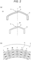
FIG. 2] FIG. 2 is a view illustrating a positional relationship between an insertion coil and a stator core in the related art. - [
FIG. 3] FIG. 3 is an explanatory view of an insertion coil and a pressing jig according to an embodiment of the present invention. - [
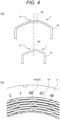
FIG. 4] FIG. 4 is a view illustrating a positional relationship between the insertion coil and a stator core according to the embodiment of the present invention. - Hereinafter, an embodiment of the present invention will be described with reference to the drawings. The following description and drawings are examples for describing the present invention, and will be omitted and simplified as appropriate for the sake of clarity of description. The present invention can be carried out in various other forms. Unless otherwise specified, each component may be singular or plural.
- Positions, sizes, shapes, ranges, and the like of components illustrated in the drawings may not represent actual positions, actual sizes, actual shapes, actual ranges, and the like in order to facilitate understanding of the invention. Therefore, the present invention is not necessarily limited to the positions, the sizes, the shapes, the ranges, and the like disclosed in the drawings.
-
- (
FIG. 1 )
Astator 100 included in a rotary electric machine includes astator coil 1 and astator core 2 on the outer periphery of a rotor (not illustrated). A plurality ofstator coils 1 arranged side by side in a radial direction are arranged in a plurality of slots (not illustrated) of thestator core 2. - (
FIG. 2 )
Astator coil 1A inserted into a stator in the related art will be described. When thestator coil 1A is inserted into astator core 2, a large-crotch stator coil 1c and a small-crotch stator coil 1d are disposed to overlap each other. Each of the large-crotch stator coil 1c and the small-crotch stator coil 1d has abent portion 8 that is bent in the radial direction at atop portion 6 which is a portion farthest from thestator core 2, in a turn portion which will be described later and is not inserted into thestator core 2. When viewed from the radial direction,bent portion axes 8a which are axes of thebent portions 8 overlaps each other. - With such a configuration, the small-
crotch stator coil 1d overlaps the large-crotch stator coil 1c when being inserted into thestator core 2. Thus, as illustrated inFIG. 2 (b) , the small-crotch stator coil 1d cannot be seen from a predetermined direction (direction from the top to the bottom inFIG. 2(a) , direction from the front to the back inFIG. 2(b) ). Thus, the small-crotch stator coil 1d is hardly pressed by the insertion jig that pushes and inserts the coil into thestator core 2. Therefore, there is a problem that the height of the coil varies after insertion, and a defect occurs in the production process. - For example, in order to solve this defect, there is a method in which all
stator coils 1A are configured to be able to be reliably pressed by thetop portion 6 is made higher to provide a margin for a space in a circumferential direction. When this configuration is applied to a large-crotchU-shaped stator coil 1a that is originally high in the axial direction, this leads to an increase in size of the entire rotary electric machine. - In addition, as a method for solving the problem without increasing the height of the
top portion 6 as described above, the coil that cannot be pressed by the insertion jig in the related art is pressed not in an axial direction but in an oblique direction or the like for adjustment to suppress variations in the height of the coil. However, when such adjustment is performed, for example, a slot liner (not illustrated) wound around eachstator coil 1A is dragged to a slot wall surface of thestator core 2, and thus the position of the slot liner may be displaced or broken, which causes a defect. - (
FIG. 3 )
A configuration of thestator coil 1 according to an embodiment of the present invention will be described. Note that, the vertical direction of the paper surface inFIG. 3(a) is the axial direction, and the vertical direction of the paper surface inFIG. 3(b) is the radial direction. - The
stator coil 1 in the present invention has alinear portion 5 and aturn portion 4. Theturn portion 4 connects twolinear portions 5, and has atop portion 6 and aninclined portion 7. Thelinear portion 5 is a portion that is inserted into thestator core 2 and penetrates different layers of the slot. Thetop portion 6 is at a position farthest from the stator core in the axial direction. Twoinclined portions 7 connect thetop portion 6 and thelinear portion 5. - The large-
crotch stator coil 1a and the small-crotch stator coil 1b, which are thestator coils 1, are inserted into thestator core 2 in an overlapping manner. Theinclined portion 7 of the large-crotch stator coil 1a is formed to be longer than theinclined portion 7 of the small-crotch stator coil 1b. Theturn portion 4 of the small-crotch stator coil 1b is at a position closer to the stator core than theturn portion 4 of the large-crotch stator coil 1a. - The large-
crotch stator coil 1a and the small-crotch stator coil 1b are at different positions without overlapping each other, when thebent portions 8 provided in therespective stator coils FIG. 3 (b) ). That is, since the position of thebent portion 8 of the large-crotch stator coil 1a is shifted in the circumferential direction from thetop portion 6, thetop portion 6 and thebent portion 8 of the small-crotch stator coil 1b are exposed when viewed from the axial direction. - As a result, when the large-
crotch stator coil 1a and the small-crotch stator coil 1b are pressed in a direction of anarrow 3c by aninsertion jig 3, the large-crotch stator coil 1a and the small-crotch stator coil 1b can be reliably pressed by a large-crotch U-shapedcoil pressing reference 3a and a small-crotch U-shapedcoil pressing reference 3b of theinsertion jig 3. Thus, it is possible to reliably insert thestator coils stator core 2, and to reduce defects in the production process. - (
FIG. 4 )
FIG. 4(a) is a separate view such that the position of thebent portion 8 illustrated inFIG. 3 (b) is different between the large-crotch stator coil 1a and the small-crotch stator coil 1b. As illustrated inFIG. 4(a) ,axes 8a of the bent portion of the large-crotch stator coil 1a and the small-crotch stator coil 1b are shifted from each other in the axial direction. Further, thebent portion 8 of the large-crotch stator coil 1a is formed at the position of theinclined portion 7 on the outer diameter side instead of thetop portion 6. - As illustrated in
FIG. 4(b) , when the large-crotch stator coil 1a and the small-crotch stator coil 1b are inserted into thestator core 2, thetop portion 6 and thebent portion 8 of the small-crotch stator coil 1b, which are exposed due to the shift of thebent portion 8 of the large-crotch stator coil 1a in the circumferential direction, have an exposed area as large as theinsertion jig 3 can directly and reliably press thetop portion 6 and thebent portion 8. - Note that the reason why the
bent portion 8 is formed on theinclined portion 7 side on the outer diameter side of theinclined portion 7 in the large-crotch stator coil 1a is that the exposed area with which the insertion jig can reliably press the small-crotch stator coil 1b is larger than that in a case where thebent portion 8 is formed at theinclined portion 7 on the inner diameter side. Since the exposed area is large, even if there is an error in design variation for eachstator coil 1, the tolerance is absorbed, and the insertion jig can reliably press the small-crotch stator coil 1b. However, thebent portion 8 may be provided at theinclined portion 7 on the inner diameter side in the large-crotch stator coil 1a if the size of the exposed area with which the insertion jig can reliably perform pressing is formed. - With such a configuration, since the
respective stator coils top portion 6 in the axial direction is not different from those of the stator coils 1c and 1d in thestator coil 1A in the related art illustrated inFIG. 2 , it is possible to contribute to size reduction in the rotary electric machine. Further, by reliably inserting the stator coils 1a and 1b, it is possible to eliminate a variation in a twisted portion of the coil (end portion of the coil). - According to the embodiment of the present invention described above, the following operational effects are obtained.
-
- (1) The rotary electric machine in the present invention includes the
stator core 2 provided with the plurality of slots, and the plurality ofstator coils 1 arranged side by side in the radial direction of thestator core 2 and arranged in the plurality of slots. Thestator coil 1 includes the twolinear portions 5 that penetrate through the slots different from each other in layers different from each other in the axial direction of thestator core 2, and theturn portion 4 that connects the twolinear portions 5. Theturn portion 4 has thetop portion 6 that is at a position farthest from thestator core 2 in the axial direction, the twoinclined portions 7 that connect thetop portion 6 and thelinear portion 5, and thebent portion 8 that is bent outward in the radial direction. Thestator coil 1 includes afirst stator coil 1a and asecond stator coil 1b that overlap each other in the axial direction. Thebent portions 8 of thefirst stator coil 1a and thesecond stator coil 1b are at different positions in the circumferential direction, thebent portion 8 of thefirst stator coil 1a is formed at theinclined portion 7 of thefirst stator coil 1a, and thebent portion 8 of thesecond stator coil 1b is formed at thetop portion 6 of thesecond stator coil 1b. Theturn portion 4 of thesecond stator coil 1b is at a position closer to thestator core 2 than theturn portion 4 of thefirst stator coil 1a in the axial direction. With such a configuration, it is possible to provide thecoil 1 of the rotary electric machine in which the height of the coil end is suppressed and a defect rate during assembly is improved. - (2) The inclined portion of the
first stator coil 1a is longer than the inclined portion of thesecond stator coil 1b. With such a configuration, it is possible to realize a configuration of thebent portion 8 in the present invention while overlapping the coils in the axial direction. - (3) The
bent portion 8 of thefirst stator coil 1a is disposed at theinclined portion 7 on the outer side of thefirst stator coil 1a in the radial direction. With such a configuration, it is possible to form a large exposed area with which theinsertion jig 3 can reliably press the small-crotch stator coil 1b. - Note that the present invention is not limited to the above embodiment, and various modifications and other configurations can be combined without departing from the gist of the present invention. In addition, the present invention is not limited to one including all the configurations described in the above embodiment, and includes one in which a portion of the configuration is deleted.
-
- 1
- stator coil
- 1a
- large-crotch stator coil
- 1b
- small-crotch stator coil
- 1c
- large-crotch stator coil in related art
- 1d
- small-crotch stator coil in related art
- 2
- stator core
- 3
- insertion jig
- 3a
- large-crotch U-shaped coil pressing reference
- 3b
- small-crotch U-shaped coil pressing reference
- 3c
- direction in which insertion jig is pressed
- 4
- turn portion
- 5
- linear portion
- 6
- top portion
- 7
- inclined portion
- 8
- bent portion
- 8a
- bent portion axis
- 100
- stator
Claims (3)
- A rotary electric machine comprising:a stator core provided with a plurality of slots; anda plurality of stator coils arranged side by side in a radial direction of the stator core and arranged in the plurality of slots,wherein the stator coil includes two linear portions that penetrate through the slots different from each other in layers different from each other in the axial direction of the stator core, and a turn portion that connects the two linear portions,the turn portion includes a top portion which is at a position farthest from the stator core in the axial direction, two inclined portions that connect the top portion and the linear portion, and a bent portion that is bent outward in the radial direction,the stator coil includes a first stator coil and a second stator coil that overlap each other in the axial direction,bent portions of the first stator coil and the second stator coil are at different positions in a circumferential direction,the bent portion of the first stator coil is formed at the inclined portion of the first stator coil,the bent portion of the second stator coil is formed at the top portion of the second stator coil, anda turn portion of the second stator coil is located closer to the stator core than a turn portion of the first stator coil in the axial direction.
- The rotary electric machine according to claim 1, wherein the inclined portion of the first stator coil is longer than the inclined portion of the second stator coil.
- The rotary electric machine according to claim 1, wherein the bent portion of the first stator coil is disposed at the inclined portion on an outer side of the first stator coil in a radial direction.
Applications Claiming Priority (1)
| Application Number | Priority Date | Filing Date | Title |
|---|---|---|---|
| PCT/JP2022/001996 WO2023139724A1 (en) | 2022-01-20 | 2022-01-20 | Rotating electric machine |
Publications (2)
| Publication Number | Publication Date |
|---|---|
| EP4468568A1 true EP4468568A1 (en) | 2024-11-27 |
| EP4468568A4 EP4468568A4 (en) | 2025-10-01 |
Family
ID=87348327
Family Applications (1)
| Application Number | Title | Priority Date | Filing Date |
|---|---|---|---|
| EP22921882.1A Pending EP4468568A4 (en) | 2022-01-20 | 2022-01-20 | ELECTRIC LATHE |
Country Status (5)
| Country | Link |
|---|---|
| US (1) | US20250112514A1 (en) |
| EP (1) | EP4468568A4 (en) |
| JP (1) | JP7830522B2 (en) |
| CN (1) | CN118633227A (en) |
| WO (1) | WO2023139724A1 (en) |
Family Cites Families (5)
| Publication number | Priority date | Publication date | Assignee | Title |
|---|---|---|---|---|
| JP6094102B2 (en) * | 2012-03-21 | 2017-03-15 | トヨタ自動車株式会社 | Segment coil, method for manufacturing the segment coil, and stator using the segment coil |
| JP5896250B2 (en) * | 2013-09-18 | 2016-03-30 | 株式会社デンソー | Rotating electric machine stator |
| WO2018003461A1 (en) * | 2016-06-30 | 2018-01-04 | 日立オートモティブシステムズ株式会社 | Dynamo-electric machine |
| EP3734804B1 (en) * | 2017-12-29 | 2023-12-06 | Odawara Engineering Co., Ltd. | Wire connection method for rotary electric machine, method for manufacturing rotary electric machine, wire connection structure for rotary electric machine, and rotary electric machine |
| JP6806194B1 (en) * | 2019-07-26 | 2021-01-06 | 株式会社明電舎 | Rotating machine winding structure |
-
2022
- 2022-01-20 WO PCT/JP2022/001996 patent/WO2023139724A1/en not_active Ceased
- 2022-01-20 US US18/728,801 patent/US20250112514A1/en active Pending
- 2022-01-20 JP JP2023574975A patent/JP7830522B2/en active Active
- 2022-01-20 CN CN202280088230.0A patent/CN118633227A/en active Pending
- 2022-01-20 EP EP22921882.1A patent/EP4468568A4/en active Pending
Also Published As
| Publication number | Publication date |
|---|---|
| WO2023139724A1 (en) | 2023-07-27 |
| US20250112514A1 (en) | 2025-04-03 |
| EP4468568A4 (en) | 2025-10-01 |
| CN118633227A (en) | 2024-09-10 |
| JPWO2023139724A1 (en) | 2023-07-27 |
| JP7830522B2 (en) | 2026-03-16 |
Similar Documents
| Publication | Publication Date | Title |
|---|---|---|
| EP3109981B1 (en) | Stator assembly method and stator assembly device | |
| KR101652564B1 (en) | Twisting device adapted to simultaneously twist a plurality of electric bar conductors for making a stator or rotor winding for an electric machine and an extractor assembly suitable for cooperating with said twisting device | |
| US10396638B2 (en) | Stator manufacturing apparatus and stator manufacturing method | |
| CN109256912B (en) | Motor manufacturing method and motor | |
| US20140215806A1 (en) | Stator manufacturing method and stator manufacturing apparatus | |
| US11489423B2 (en) | Aligning apparatus and method of manufacturing aligned coil | |
| US10411569B2 (en) | Rotor and rotor manufacturing method | |
| US20170310176A1 (en) | Rotor, method of manufacturing rotor, and rotary electric machine including rotor | |
| JP6723475B2 (en) | Armature core of rotating electric machine and method of manufacturing armature core of rotating electric machine | |
| US20210111612A1 (en) | Method And Device For Twisting A Winding Head Of A Stator And Stator For An Electrical Machine | |
| US20190296621A1 (en) | Twisting and bending device | |
| JP5177512B2 (en) | Assembly method of split core type stator of inner rotor type rotating electrical machine | |
| US9577486B2 (en) | Conductor retention member for a stator assembly | |
| JP2018074689A (en) | Insulating sheet inserting device, insulating sheet inserting method, stator manufacturing device, motor | |
| JP2012222970A (en) | Coil terminal processing structure of stator in electric motor, and coil terminal processing method of the same | |
| JP5241845B2 (en) | Winding device winding frame and coil mounting method | |
| US20250112514A1 (en) | Rotary Electric Machine | |
| JP6705789B2 (en) | Stator assembly method | |
| JP2000050581A (en) | Stator manufacturing equipment and stator | |
| JP5155782B2 (en) | Armature and motor | |
| US20240235313A1 (en) | Winding overhang guide, and associated wound rotor and winding method | |
| EP3032041A1 (en) | Rotor heat shield and method for securing the same into a rotor assembly | |
| EP4503389A1 (en) | Stator core, stator core manufacturing method, and rotary electric machine | |
| US20250119020A1 (en) | Insulator, stator, rotating electric machine, and method for manufacturing stator | |
| JP7596958B2 (en) | Armature manufacturing apparatus and armature manufacturing method |
Legal Events
| Date | Code | Title | Description |
|---|---|---|---|
| STAA | Information on the status of an ep patent application or granted ep patent |
Free format text: STATUS: THE INTERNATIONAL PUBLICATION HAS BEEN MADE |
|
| PUAI | Public reference made under article 153(3) epc to a published international application that has entered the european phase |
Free format text: ORIGINAL CODE: 0009012 |
|
| STAA | Information on the status of an ep patent application or granted ep patent |
Free format text: STATUS: REQUEST FOR EXAMINATION WAS MADE |
|
| 17P | Request for examination filed |
Effective date: 20240820 |
|
| AK | Designated contracting states |
Kind code of ref document: A1 Designated state(s): AL AT BE BG CH CY CZ DE DK EE ES FI FR GB GR HR HU IE IS IT LI LT LU LV MC MK MT NL NO PL PT RO RS SE SI SK SM TR |
|
| DAV | Request for validation of the european patent (deleted) | ||
| DAX | Request for extension of the european patent (deleted) | ||
| RAP3 | Party data changed (applicant data changed or rights of an application transferred) |
Owner name: ASTEMO, LTD. |
|
| A4 | Supplementary search report drawn up and despatched |
Effective date: 20250902 |
|
| RIC1 | Information provided on ipc code assigned before grant |
Ipc: H02K 3/04 20060101AFI20250827BHEP Ipc: H02K 15/0643 20250101ALI20250827BHEP |