EP4468564A2 - Geteilter motorstator und herstellungsverfahren dafür - Google Patents
Geteilter motorstator und herstellungsverfahren dafür Download PDFInfo
- Publication number
- EP4468564A2 EP4468564A2 EP24172636.3A EP24172636A EP4468564A2 EP 4468564 A2 EP4468564 A2 EP 4468564A2 EP 24172636 A EP24172636 A EP 24172636A EP 4468564 A2 EP4468564 A2 EP 4468564A2
- Authority
- EP
- European Patent Office
- Prior art keywords
- core
- split
- motor stator
- type motor
- partition wall
- Prior art date
- Legal status (The legal status is an assumption and is not a legal conclusion. Google has not performed a legal analysis and makes no representation as to the accuracy of the status listed.)
- Pending
Links
Images




Classifications
-
- H—ELECTRICITY
- H02—GENERATION; CONVERSION OR DISTRIBUTION OF ELECTRIC POWER
- H02K—DYNAMO-ELECTRIC MACHINES
- H02K1/00—Details of the magnetic circuit
- H02K1/06—Details of the magnetic circuit characterised by the shape, form or construction
- H02K1/12—Stationary parts of the magnetic circuit
- H02K1/16—Stator cores with slots for windings
- H02K1/165—Shape, form or location of the slots
-
- H—ELECTRICITY
- H02—GENERATION; CONVERSION OR DISTRIBUTION OF ELECTRIC POWER
- H02K—DYNAMO-ELECTRIC MACHINES
- H02K1/00—Details of the magnetic circuit
- H02K1/06—Details of the magnetic circuit characterised by the shape, form or construction
- H02K1/12—Stationary parts of the magnetic circuit
- H02K1/18—Means for mounting or fastening magnetic stationary parts on to, or to, the stator structures
-
- H—ELECTRICITY
- H02—GENERATION; CONVERSION OR DISTRIBUTION OF ELECTRIC POWER
- H02K—DYNAMO-ELECTRIC MACHINES
- H02K1/00—Details of the magnetic circuit
- H02K1/06—Details of the magnetic circuit characterised by the shape, form or construction
- H02K1/12—Stationary parts of the magnetic circuit
- H02K1/18—Means for mounting or fastening magnetic stationary parts on to, or to, the stator structures
- H02K1/185—Means for mounting or fastening magnetic stationary parts on to, or to, the stator structures to outer stators
-
- H—ELECTRICITY
- H02—GENERATION; CONVERSION OR DISTRIBUTION OF ELECTRIC POWER
- H02K—DYNAMO-ELECTRIC MACHINES
- H02K15/00—Processes or apparatus specially adapted for manufacturing, assembling, maintaining or repairing of dynamo-electric machines
- H02K15/02—Processes or apparatus specially adapted for manufacturing, assembling, maintaining or repairing of dynamo-electric machines of stator or rotor bodies
- H02K15/021—Magnetic cores
-
- H—ELECTRICITY
- H02—GENERATION; CONVERSION OR DISTRIBUTION OF ELECTRIC POWER
- H02K—DYNAMO-ELECTRIC MACHINES
- H02K15/00—Processes or apparatus specially adapted for manufacturing, assembling, maintaining or repairing of dynamo-electric machines
- H02K15/08—Forming windings by laying conductors into or around core parts
- H02K15/085—Forming windings by laying conductors into or around core parts by laying conductors into slotted stators
-
- H—ELECTRICITY
- H02—GENERATION; CONVERSION OR DISTRIBUTION OF ELECTRIC POWER
- H02K—DYNAMO-ELECTRIC MACHINES
- H02K15/00—Processes or apparatus specially adapted for manufacturing, assembling, maintaining or repairing of dynamo-electric machines
- H02K15/13—Applying slot closure means in the cores; Manufacture of slot closure means
-
- H—ELECTRICITY
- H02—GENERATION; CONVERSION OR DISTRIBUTION OF ELECTRIC POWER
- H02K—DYNAMO-ELECTRIC MACHINES
- H02K3/00—Details of windings
- H02K3/04—Windings characterised by the conductor shape, form or construction, e.g. with bar conductors
- H02K3/12—Windings characterised by the conductor shape, form or construction, e.g. with bar conductors arranged in slots
- H02K3/14—Windings characterised by the conductor shape, form or construction, e.g. with bar conductors arranged in slots with transposed conductors, e.g. twisted conductors
-
- H—ELECTRICITY
- H02—GENERATION; CONVERSION OR DISTRIBUTION OF ELECTRIC POWER
- H02K—DYNAMO-ELECTRIC MACHINES
- H02K3/00—Details of windings
- H02K3/46—Fastening of windings on the stator or rotor structure
- H02K3/48—Fastening of windings on the stator or rotor structure in slots
- H02K3/487—Slot-closing devices
-
- H—ELECTRICITY
- H02—GENERATION; CONVERSION OR DISTRIBUTION OF ELECTRIC POWER
- H02K—DYNAMO-ELECTRIC MACHINES
- H02K1/00—Details of the magnetic circuit
- H02K1/06—Details of the magnetic circuit characterised by the shape, form or construction
- H02K1/12—Stationary parts of the magnetic circuit
- H02K1/14—Stator cores with salient poles
- H02K1/146—Stator cores with salient poles consisting of a generally annular yoke with salient poles
- H02K1/148—Sectional cores
-
- H—ELECTRICITY
- H02—GENERATION; CONVERSION OR DISTRIBUTION OF ELECTRIC POWER
- H02K—DYNAMO-ELECTRIC MACHINES
- H02K15/00—Processes or apparatus specially adapted for manufacturing, assembling, maintaining or repairing of dynamo-electric machines
- H02K15/02—Processes or apparatus specially adapted for manufacturing, assembling, maintaining or repairing of dynamo-electric machines of stator or rotor bodies
Definitions
- the following disclosure relates to a stator included in an electric motor.
- a coil winding method used in a conventional motor stator is largely divided into two types: hairpin winding and continuous winding.
- the hairpin winding method is a method of sequentially inserting square copper wire coils formed into a U shape (hairpin shape) into slots of a stator core in an axial direction, and then welding and connecting ends of each coil.
- the hairpin winding method is advantageous in terms of process simplification because the process is completed by inserting the square copper wire coil between stator shoes without the need to manufacture a winding bundle in advance, but is inefficient in terms of production cost and time because it requires welding end portions of the plurality of square copper wire coils and then layering a protective coating.
- welding defects inevitably occur.
- in the case of the hairpin winding method there was a problem in that an axial length of the stator became longer as the end portion of the square copper wire coil that requires welding protruded long to the outside of the stator.
- the continuous winding method is a method of bending a square copper wire coil without breaking the square copper wire coil, performing coil welding only at limited locations to make a winding bundle, and then radially inserting the winding bundle into a slot of a stator core.
- the continuous winding method has the advantage of increasing the ease of assembly between the stator and the winding by allowing the pre-fabricated winding to be inserted into the stator at once, and has an advantage over the hairpin winding method in terms of production cost and time because there are not many welded areas by making each winding strand intertwined to support each position
- the continuous winding method has the advantage of reducing the axial length of the stator compared to the hairpin winding method since each winding strand is intertwined so that the ends thereof do not protrude outside the stator.
- the continuous winding method also has a problem.
- the continuous winding method has the problem of low NVH performance since the empty space increases and thus cogging torque ripple occurs.
- Patent Document 1 Korea Patent Laid-Open Publication No. 10-2020-0016088 "Stator Fabricating Method for Hairpin Winding Motor” February 14, 2020
- An embodiment of the present invention is directed to providing a split-type motor stator that is configured to separate a stator core into an inner core and an outer core so that an entrance of a slot into which a coil is inserted can be opened and closed to compensate for problems of a continuous winding method, thereby having advantages of a hairpin winding method, and a manufacturing method thereof.
- an embodiment of the present invention is directed to providing a split-type motor stator that is configured to separate a stator core into an inner core and an outer core so that an entrance of a slot into which a coil is inserted can be opened and closed, thereby reducing wasted scrap by using split cores instead of whole cores to save material costs, removing the welding and coating processes on a coil to improve a defect rate, connecting shoes to each other even after a winding bundle is inserted to remove cogging torque ripple and improve NVH performance, inserting the coil into the slot with the coil in close contact to increase a coil acceptance rate and secure a high loading rate, and reducing a motor size to reduce an axial coil length.
- a split-type motor stator having a coil assembly, which includes a plurality of coil strands, provided therein includes: a first core located on a first side in a direction of a rotation axis of the coil assembly and including a receiving groove into which the coil strand is inserted; and a second core located on a second side of the coil assembly and coupled to the first core to fix a position of the coil assembly.
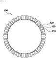
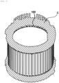
- the first core may include a first central portion shaped of a hollow cylinder, and partition walls protruding in a radial direction from an outer peripheral surface of the first central portion, the partition walls may be spaced apart from each other at regular intervals along the outer peripheral surface of the first central portion, and the receiving groove may be a space formed surrounded by the partition walls and the first central portion.
- the partition walls adjacent to each other may be formed so that opposing surfaces are in parallel.
- the second core may include: a second central portion shaped of the hollow cylinder, and a coupling protrusion formed to protrude on an inner peripheral surface of the second central portion, but formed at a position corresponding to the partition wall so that a protruding surface contacts the protruding surface of the partition wall.
- the second core may be formed by assembling a plurality of pieces divided in a circumferential direction thereof.
- the partition wall may have a protrusion or a groove formed on the protruding surface, and the protruding surface of the coupling protrusion may be formed with a protrusion or a groove to correspond to a shape of one end surface of the partition wall.
- the split-type motor stator may further include a fixing member coupled to an outer peripheral surface of the second core and compressing the second core in the radial direction.
- a method of manufacturing a split-type motor stator includes: (a) manufacturing and preparing a first core and a second core to be coupled to each other; (b) assembling the first core and a coil assembly by inserting a coil strand into a receiving groove of the first core; and (c) assembling the first core and the second core to fix a position of the coil assembly.
- the step (c) may include: (c1) assembling a plurality of pieces constituting the second core to the first core, respectively, and (c2) inserting a fixing member into an outer peripheral surface of the second core to compress the second core in a radial direction.
- the step (a) may include: (a1) forming a protrusion or a groove on a protruding surface of a partition of the first core; and (a2) forming a protrusion or a groove corresponding to a shape of one end surface of the partition wall on the protruding surface of the coupling protrusion of the second core.
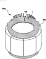
- the present invention relates to a split-type motor stator 1000 having a coil assembly C, which includes a plurality of coil strands, provided therein.
- the split-type motor stator 1000 of the present invention includes a first core 100 and a second core 100, and the first core 100 and the second core 200 may be manufactured individually and assembled when inserting the coil assembly C.
- the first core 100 may be located closer to a rotation axis or a rotor than the second core 200, that is, located on the inside, may be located closer to the rotation axis with respect to the coil assembly C, and include a receiving groove 110 into which the coil strand is inserted.
- the second core 200 may be located farther away from the rotation axis or rotor than the first core 100, that is, on the outside. More specifically, it may be located farther away from the rotation axis with respect to the coil assembly C.
- the second core 200 may be coupled to the first core 100 to fix the position of the coil assembly C.
- the first core 100 and the second core 200 may be separately formed to increase the coupling performance with the coil assembly C, and the coil assembly C is inserted into the first core 100 located on the inside, that is, the coil assembly C is inserted from the outside to the inside and only the outside of the second core 200 is compressed, so a significant portion of a gap between coil strands may be removed and a coil size may be increased by the amount of empty space.
- the related art reduction in resistance, improvement in efficiency
- the second core 200 may be formed in a shape of a hollow cylinder, and may be formed in a form in which a plurality of pieces divided along a circumferential direction are assembled. In this case, the pieces constituting the second core 200 may be equally divided into the same size and shape. In this way, the second core 200 is formed by being divided into a plurality of pieces, so even if an outermost outer diameter of the first core 100 and an innermost inner diameter of the second core 200 are designed to be the same (minimizing gaps), the first core 100 and the second core 200 may be easily coupled without the need for being fitted.
- the partition walls 130 adjacent to each other may be formed so that opposing surfaces are in parallel. That is, a cross-sectional area of the partition wall 130 may become wider as the partition wall 130 is farther away from the first central portion 120, that is, as it moves outward.
- the shape of the receiving groove 110 in which the coil assembly C is received may be formed in the shape of a rectangular parallelepiped with one side open, and when the coil strands are stacked along the radial direction in the receiving groove 110, each coil strand may be supported with uniform force regardless of its position.
- the second core 200 includes a second central portion 210 in the shape of a hollow cylinder, and a coupling protrusion 212 that protrudes from an inner peripheral surface of the second central portion 210 and formed at a position corresponding to the partition wall 130.
- the second central portion 210 and the coupling protrusion 212 may be formed integrally.
- a boundary of each piece may only be formed at a location that does not divide the coupling protrusion 212. Accordingly, it is possible to prevent the coupling force between the coupling protrusion 212 and the partition wall 130 from being reduced due to the boundary surface of the pieces.
- the coupling protrusion 212 of the second core 200 may be coupled so that an end protruding surface is in contact with an end protruding surface of the partition wall 130 of the first core 100. Since the second core 200 includes the protruding coupling protrusion 212, when the first core 100 and the second core 200 are coupled, the coupling position of the first core 100 and the second core 200 may be fixed. Furthermore, the protruding surface of the partition wall 130 may be formed with a protrusion or a groove, and the protruding surface of the coupling protrusion 212 may be formed with a protrusion or a groove to correspond to the shape of the one end surface of the partition wall 130. Accordingly, the coupling strength of the coupling protrusion 212 and the partition wall 130 increases, thereby improving the structural stability of the split-type motor stator 1000 of the present invention.
- the split-type motor stator 1000 of the present invention may further include the fixing member 300 to strengthen the coupling force of the first core 100 and the second core 200.
- the fixing member 300 may be coupled to an outer peripheral surface of the second core 200, so the second core 200 may be compressed in the radial direction.
- the fixing member 300 may be a support ring fitted in an outer surface of the second core 200, or may be carbon fiber wound around the outer surface of the second core 200.
- the present invention relates to a method of manufacturing a split-type motor stator 1000, and the method may include (a) manufacturing and preparing the first core 100 and the second core 200 to be coupled to each other; (b) assembling the first core 100 and the coil assembly C by inserting the coil strand into the receiving groove 110 of the first core 100; and (c) assembling the first core 100 and the second core 200 to fix the position of the coil assembly C.
- the first core 100 having a plurality of receiving grooves 110 and having a hollow center and the second core 200 formed to correspond to the first core 100 may be manufactured.
- the size of the receiving groove 110 of the first core 100 may be designed in consideration of the thickness of the coil strand of the coil assembly C.
- step (b) performed later as illustrated in FIG. 8 , the coil assembly C manufactured by a continuous winding method may be fitted and coupled to the receiving groove 110 of the first core 100.
- the coil assembly C may be inserted into the first core 100 from the outside to the inside, so a significant portion of the gap between the coil strands may be removed simply by compressing the outside of the second core 200 and the higher loading rate may be secured than the related art.
- step (c) may include (c1) assembling the plurality of pieces forming the second core 200 to the first core 100, respectively, and (c2) inserting the fixing member 300 into the outer peripheral surface of the second core 200 and compressing the second core 200 in the radial direction.
- the pieces constituting the second core 200 may be divided in a circumferential direction and may be equally divided into the same size and shape.
- the second core 200 is formed by being divided into a plurality of pieces, so even if an outermost outer diameter of the first core 100 and an innermost inner diameter of the second core 200 are designed to be the same (minimizing gaps), the first core 100 and the second core 200 may be easily coupled without the need for being fitted.
- the fixing member 300 may be a support ring fitted in an outer surface of the second core 200, or may be carbon fiber wound around the outer surface of the second core 200.
- step (a) preferably includes (a1) forming the protrusion or groove on the protruding surface of the partition wall 130 of the first core 100 and (a2) forming the protrusion or groove corresponding to the one end surface shape of the partition wall 130 on the protruding surface of the coupling protrusion 212 of the second core 200. Accordingly, the coupling strength of the coupling protrusion 212 and the partition wall 130 increases, thereby improving the structural stability of the split-type motor stator 1000 of the present invention.
- the stator core is separated into the inner core and outer core so that the entrance of the slot into which the coil is inserted can be opened and closed, thereby compensating for the problems of the continuous winding method and achieving the advantages of the hairpin winding method.
- stator core into the inner core and outer core so that the entrance of the slot into which a coil is inserted can be opened and closed, it is possible to reduce wasted scrap by using split cores instead of whole cores to save material costs, remove the welding and coating processes on the coil to improve a defect rate, connect shoes to each other even after a winding bundle is inserted to remove cogging torque ripple and improve NVH performance, insert the coil into the slot with the coil in close contact to increase a coil acceptance rate and secure a high loading rate, and reduce a motor size to reduce an axial coil length.
Landscapes
- Engineering & Computer Science (AREA)
- Power Engineering (AREA)
- Manufacturing & Machinery (AREA)
- Iron Core Of Rotating Electric Machines (AREA)
- Manufacture Of Motors, Generators (AREA)
Applications Claiming Priority (1)
| Application Number | Priority Date | Filing Date | Title |
|---|---|---|---|
| KR1020230066137A KR20240168595A (ko) | 2023-05-23 | 2023-05-23 | 분할형 모터 고정자 및 분할형 모터 고정자의 제작방법 |
Publications (2)
| Publication Number | Publication Date |
|---|---|
| EP4468564A2 true EP4468564A2 (de) | 2024-11-27 |
| EP4468564A3 EP4468564A3 (de) | 2025-04-02 |
Family
ID=90922670
Family Applications (1)
| Application Number | Title | Priority Date | Filing Date |
|---|---|---|---|
| EP24172636.3A Pending EP4468564A3 (de) | 2023-05-23 | 2024-04-26 | Geteilter motorstator und herstellungsverfahren dafür |
Country Status (4)
| Country | Link |
|---|---|
| US (1) | US20240396385A1 (de) |
| EP (1) | EP4468564A3 (de) |
| KR (1) | KR20240168595A (de) |
| CN (1) | CN222531385U (de) |
Citations (2)
| Publication number | Priority date | Publication date | Assignee | Title |
|---|---|---|---|---|
| EP1499000B1 (de) * | 2003-07-12 | 2006-04-26 | Grundfos a/s | Segmentierter Stator |
| KR20200016088A (ko) | 2018-08-06 | 2020-02-14 | 정진호 | 헤어핀 권선모터에서의 지그를 이용한 고정자 제조방법 |
Family Cites Families (4)
| Publication number | Priority date | Publication date | Assignee | Title |
|---|---|---|---|---|
| JP6305203B2 (ja) * | 2014-05-19 | 2018-04-04 | 三菱電機株式会社 | 回転電機の固定子及び固定子の製造方法 |
| WO2017158700A1 (ja) * | 2016-03-14 | 2017-09-21 | 株式会社安川電機 | 回転電機、回転電機の製造方法 |
| FR3082376B1 (fr) * | 2018-06-07 | 2020-07-17 | Moteurs Leroy-Somer | Stator de machine electrique tournante |
| US20240195234A1 (en) * | 2021-04-14 | 2024-06-13 | Hyperdrives Gmbh | Stator for a rotating electrical machine |
-
2023
- 2023-05-23 KR KR1020230066137A patent/KR20240168595A/ko active Pending
-
2024
- 2024-04-10 US US18/631,435 patent/US20240396385A1/en active Pending
- 2024-04-26 EP EP24172636.3A patent/EP4468564A3/de active Pending
- 2024-05-22 CN CN202421129545.8U patent/CN222531385U/zh active Active
Patent Citations (2)
| Publication number | Priority date | Publication date | Assignee | Title |
|---|---|---|---|---|
| EP1499000B1 (de) * | 2003-07-12 | 2006-04-26 | Grundfos a/s | Segmentierter Stator |
| KR20200016088A (ko) | 2018-08-06 | 2020-02-14 | 정진호 | 헤어핀 권선모터에서의 지그를 이용한 고정자 제조방법 |
Also Published As
| Publication number | Publication date |
|---|---|
| EP4468564A3 (de) | 2025-04-02 |
| KR20240168595A (ko) | 2024-12-02 |
| US20240396385A1 (en) | 2024-11-28 |
| CN222531385U (zh) | 2025-02-25 |
Similar Documents
| Publication | Publication Date | Title |
|---|---|---|
| US20210399603A1 (en) | Stator assembly of hairpin winding motor | |
| US8044551B2 (en) | Stator for electric motor and manufacturing method thereof | |
| US11799340B2 (en) | Stator assembly of hairpin winding motor and manufacturing method thereof | |
| JP6341288B2 (ja) | ステータ組立方法及びステータ | |
| JP5911018B2 (ja) | 電機子およびその電機子を備えた回転電機 | |
| US20240322630A1 (en) | Motor, stator, and manufacturing method of stator | |
| US20240195272A1 (en) | Structure and manufacturing method of axial flux electric machine stator | |
| US7449804B2 (en) | Stator of reciprocating motor | |
| US11888349B2 (en) | Stator assembly of hairpin winding motor and manufacturing method thereof | |
| KR102688105B1 (ko) | 고정자 어셈블리용 웨지부재 및 헤어핀 권선모터의 고정자 어셈블리 | |
| JPH10304608A (ja) | 電動機 | |
| JP5390869B2 (ja) | 積層鉄心及びその製造方法 | |
| EP4468564A2 (de) | Geteilter motorstator und herstellungsverfahren dafür | |
| WO2019148063A1 (en) | Stepped stator for an electric motor | |
| CN111628590A (zh) | 定子、马达、车辆以及线圈制造方法 | |
| EP1467470B1 (de) | Läufer einer elektrischen Drehmaschine sowie Verfahren zu seiner Herstellung | |
| CN108347116B (zh) | 一种绝缘框架、定子总成及电机 | |
| CN112821630B (zh) | 防止极爪变形的定子骨架组件和包括其的步进电机 | |
| JP7436764B1 (ja) | コイルユニット、コイルアセンブリ及びエネルギー変換器 | |
| CN119605056A (zh) | 分段式定子芯、电机和用于制造电机的定子组件的方法 | |
| KR102657931B1 (ko) | 베어링 전압비 저감형 스테이터 코어 | |
| EP4503388A1 (de) | Motor, stator und herstellungsverfahren für den stator | |
| CN114825687B (zh) | 一种外转子电机定子结构 | |
| US12587047B2 (en) | Segmented stator core for an electric motor | |
| US20260106499A1 (en) | Stator of an electric machine, motor vehicle |
Legal Events
| Date | Code | Title | Description |
|---|---|---|---|
| PUAI | Public reference made under article 153(3) epc to a published international application that has entered the european phase |
Free format text: ORIGINAL CODE: 0009012 |
|
| STAA | Information on the status of an ep patent application or granted ep patent |
Free format text: STATUS: THE APPLICATION HAS BEEN PUBLISHED |
|
| AK | Designated contracting states |
Kind code of ref document: A2 Designated state(s): AL AT BE BG CH CY CZ DE DK EE ES FI FR GB GR HR HU IE IS IT LI LT LU LV MC ME MK MT NL NO PL PT RO RS SE SI SK SM TR |
|
| PUAL | Search report despatched |
Free format text: ORIGINAL CODE: 0009013 |
|
| AK | Designated contracting states |
Kind code of ref document: A3 Designated state(s): AL AT BE BG CH CY CZ DE DK EE ES FI FR GB GR HR HU IE IS IT LI LT LU LV MC ME MK MT NL NO PL PT RO RS SE SI SK SM TR |
|
| RIC1 | Information provided on ipc code assigned before grant |
Ipc: H02K 15/02 20060101ALN20250227BHEP Ipc: H02K 1/14 20060101ALN20250227BHEP Ipc: H02K 1/16 20060101AFI20250227BHEP |
|
| STAA | Information on the status of an ep patent application or granted ep patent |
Free format text: STATUS: REQUEST FOR EXAMINATION WAS MADE |
|
| 17P | Request for examination filed |
Effective date: 20251001 |
|
| STAA | Information on the status of an ep patent application or granted ep patent |
Free format text: STATUS: EXAMINATION IS IN PROGRESS |
|
| 17Q | First examination report despatched |
Effective date: 20251128 |