EP4468550A1 - Power generation module management device - Google Patents
Power generation module management device Download PDFInfo
- Publication number
- EP4468550A1 EP4468550A1 EP22922117.1A EP22922117A EP4468550A1 EP 4468550 A1 EP4468550 A1 EP 4468550A1 EP 22922117 A EP22922117 A EP 22922117A EP 4468550 A1 EP4468550 A1 EP 4468550A1
- Authority
- EP
- European Patent Office
- Prior art keywords
- power generation
- generation module
- power
- management device
- fuel
- Prior art date
- Legal status (The legal status is an assumption and is not a legal conclusion. Google has not performed a legal analysis and makes no representation as to the accuracy of the status listed.)
- Pending
Links
Images






Classifications
-
- G—PHYSICS
- G06—COMPUTING OR CALCULATING; COUNTING
- G06Q—INFORMATION AND COMMUNICATION TECHNOLOGY [ICT] SPECIALLY ADAPTED FOR ADMINISTRATIVE, COMMERCIAL, FINANCIAL, MANAGERIAL OR SUPERVISORY PURPOSES; SYSTEMS OR METHODS SPECIALLY ADAPTED FOR ADMINISTRATIVE, COMMERCIAL, FINANCIAL, MANAGERIAL OR SUPERVISORY PURPOSES, NOT OTHERWISE PROVIDED FOR
- G06Q10/00—Administration; Management
- G06Q10/04—Forecasting or optimisation specially adapted for administrative or management purposes, e.g. linear programming or "cutting stock problem"
-
- G—PHYSICS
- G06—COMPUTING OR CALCULATING; COUNTING
- G06Q—INFORMATION AND COMMUNICATION TECHNOLOGY [ICT] SPECIALLY ADAPTED FOR ADMINISTRATIVE, COMMERCIAL, FINANCIAL, MANAGERIAL OR SUPERVISORY PURPOSES; SYSTEMS OR METHODS SPECIALLY ADAPTED FOR ADMINISTRATIVE, COMMERCIAL, FINANCIAL, MANAGERIAL OR SUPERVISORY PURPOSES, NOT OTHERWISE PROVIDED FOR
- G06Q10/00—Administration; Management
- G06Q10/06—Resources, workflows, human or project management; Enterprise or organisation planning; Enterprise or organisation modelling
- G06Q10/063—Operations research, analysis or management
-
- G—PHYSICS
- G06—COMPUTING OR CALCULATING; COUNTING
- G06Q—INFORMATION AND COMMUNICATION TECHNOLOGY [ICT] SPECIALLY ADAPTED FOR ADMINISTRATIVE, COMMERCIAL, FINANCIAL, MANAGERIAL OR SUPERVISORY PURPOSES; SYSTEMS OR METHODS SPECIALLY ADAPTED FOR ADMINISTRATIVE, COMMERCIAL, FINANCIAL, MANAGERIAL OR SUPERVISORY PURPOSES, NOT OTHERWISE PROVIDED FOR
- G06Q10/00—Administration; Management
- G06Q10/20—Administration of product repair or maintenance
-
- G—PHYSICS
- G06—COMPUTING OR CALCULATING; COUNTING
- G06Q—INFORMATION AND COMMUNICATION TECHNOLOGY [ICT] SPECIALLY ADAPTED FOR ADMINISTRATIVE, COMMERCIAL, FINANCIAL, MANAGERIAL OR SUPERVISORY PURPOSES; SYSTEMS OR METHODS SPECIALLY ADAPTED FOR ADMINISTRATIVE, COMMERCIAL, FINANCIAL, MANAGERIAL OR SUPERVISORY PURPOSES, NOT OTHERWISE PROVIDED FOR
- G06Q50/00—Information and communication technology [ICT] specially adapted for implementation of business processes of specific business sectors, e.g. utilities or tourism
- G06Q50/06—Energy or water supply
-
- H—ELECTRICITY
- H02—GENERATION; CONVERSION OR DISTRIBUTION OF ELECTRIC POWER
- H02J—ELECTRIC POWER NETWORKS; CIRCUIT ARRANGEMENTS OR SYSTEMS FOR SUPPLYING OR DISTRIBUTING ELECTRIC POWER; SYSTEMS FOR STORING ELECTRIC ENERGY
- H02J3/00—Circuit arrangements for AC mains or AC distribution networks
- H02J3/007—Arrangements for selectively connecting one or more loads to one or more power sources or power lines
- H02J3/0075—Arrangements for selectively connecting one or more loads to one or more power sources or power lines for providing alternative feeding paths between load and source according to economic or energy efficiency considerations, e.g. economic dispatch
-
- H—ELECTRICITY
- H02—GENERATION; CONVERSION OR DISTRIBUTION OF ELECTRIC POWER
- H02J—ELECTRIC POWER NETWORKS; CIRCUIT ARRANGEMENTS OR SYSTEMS FOR SUPPLYING OR DISTRIBUTING ELECTRIC POWER; SYSTEMS FOR STORING ELECTRIC ENERGY
- H02J3/00—Circuit arrangements for AC mains or AC distribution networks
- H02J3/38—Arrangements for feeding a single network from two or more generators or sources in parallel; Arrangements for feeding already energised networks from additional generators or sources in parallel
- H02J3/46—Controlling the sharing of generated power between the generators, sources or networks
- H02J3/466—Scheduling or selectively controlling the operation of the generators or sources, e.g. connecting or disconnecting generators to meet a demand
-
- H—ELECTRICITY
- H02—GENERATION; CONVERSION OR DISTRIBUTION OF ELECTRIC POWER
- H02J—ELECTRIC POWER NETWORKS; CIRCUIT ARRANGEMENTS OR SYSTEMS FOR SUPPLYING OR DISTRIBUTING ELECTRIC POWER; SYSTEMS FOR STORING ELECTRIC ENERGY
- H02J2101/00—Supply or distribution of decentralised, dispersed or local electric power generation
- H02J2101/20—Dispersed power generation using renewable energy sources
-
- H—ELECTRICITY
- H02—GENERATION; CONVERSION OR DISTRIBUTION OF ELECTRIC POWER
- H02J—ELECTRIC POWER NETWORKS; CIRCUIT ARRANGEMENTS OR SYSTEMS FOR SUPPLYING OR DISTRIBUTING ELECTRIC POWER; SYSTEMS FOR STORING ELECTRIC ENERGY
- H02J2101/00—Supply or distribution of decentralised, dispersed or local electric power generation
- H02J2101/20—Dispersed power generation using renewable energy sources
- H02J2101/30—Fuel cells
-
- H—ELECTRICITY
- H02—GENERATION; CONVERSION OR DISTRIBUTION OF ELECTRIC POWER
- H02J—ELECTRIC POWER NETWORKS; CIRCUIT ARRANGEMENTS OR SYSTEMS FOR SUPPLYING OR DISTRIBUTING ELECTRIC POWER; SYSTEMS FOR STORING ELECTRIC ENERGY
- H02J3/00—Circuit arrangements for AC mains or AC distribution networks
- H02J3/003—Load forecast, e.g. methods or systems for forecasting future load demand
Definitions
- the present invention relates to a technology for managing a power generation module having an engine.
- RE Renewable Energy
- RE fuel fuel derived from renewable energy such as hydrogen
- the range for handling power generation output fluctuations when using the facility is an operation range of 30 to 100%, and thus compatibility with fluctuating renewable energy is low.
- the facility installation site is fixed, an examination in combination with power line reinforcement are required, and thus additional asset costs are incurred.
- the fuel range to be used in large-scale thermal power generation is limited, it is difficult to flexibly handle existing fuels and RE fuels available in the region. Therefore, in order to shorten the facility investment recovery period, a power generation system capable of handling varying RE fuel through slight improvement of existing assets is required.
- an asset service that implements flexible power generation utilizing regional RE fuel by adapting existing mass-produced engines such as automobile engines and industrial engines to renewable energy-derived fuels and by using a low-cost engine generator capable of handling fluctuations that combines a plurality of such engines.
- PTL 1 discloses an invention related to a power generation system for which a vehicle engine is repurposed as a stationary engine generator and which combines a plurality of such engine generators.
- an engine-type power generation device includes a plurality of vehicle engine generators, a fuel supply unit, an operation controller, and a state measuring instrument that measures operation state data of each engine
- a management system includes a database unit that stores device information relating to a user and an installation site of the engine-type power generation device, operation state data, and engine information including a specification or a model of the vehicle engine, a data reception unit that receives the operation state data from the engine-type power generation device via a data communication line and stores the operation state data in the database unit, and a replacement-required engine detection unit that, on the basis of the operation state data, detects and specifies that the vehicle engine in a failed state or the like is included in the engine-type power generation device.
- PTL 1 discloses failure diagnosis after introducing an engine-type power generation device, but does not disclose an examination of the type of power generation device at the time of the introduction. In addition, there are no disclosures relating to the fuel type to be used in handling the RE fuel. For this reason, it is difficult to handle the risk of failure after introducing stationary power generation corresponding to RE fuel and the shortening of the lead times for maintenance and servicing.
- a power generation module management device is a power generation module management device that is used by a power consumer and that manages, according to an amount of power requested by the power consumer, a configuration of power generation sources including at least one power generation module, the device including: a storage unit that records power demand information relating to the amount of power requested by the power consumer and a procurable power generation module list in which procurable power generation modules are recorded, wherein the device selects the power generation module capable of outputting the amount of power requested by the power consumer, from the procurable power generation module list, on a basis of the power demand information and a type of fuel available to the power consumer.
- the present invention it is possible to reduce risk of failure, improve ease of servicing and maintenance, and shorten a lead time by selecting an engine generator that can be provided for an energy demand situation of a power consumer and the type of RE fuel that can be used, and by selecting an engine generator according to a state of health of the engine generator.
- the optimal number of devices and the optimal type of devices can be selected according to the energy consumption of the power consumer and the available fuel type, the optimal power can be supplied to the power consumer, and the effective use of the energy resources and the reduction of CO 2 can be implemented at low cost.
- FIG. 1 is a block diagram to illustrate a relationship between a power generation module management device 1 and a power consumer according to an embodiment of the present invention.
- the power generation module management device 1 includes a storage unit 100, determines the required configuration of a power generation module on the basis of, for example, power demand information 103 and operational information 102 related to an amount of power required by a power consumer such as a factory, and selects power generation modules by referring to the procurable power generation module list 101.
- the power generation module management device 1 includes a power supply information evaluation unit 16, an engine performance information calculation unit 15, an engine selection unit 14, a power generation module selection unit 13, a cost/CO 2 discharge amount calculation unit 12, and a communication unit 11.
- the power generation module management device 1 further includes the storage unit 100.
- the storage unit 100 stores power demand information 103 of a power consumer, operational information 102, and a procurable power generation module list 101.
- the power generation module management device 1 selects and determines, on the basis of the power demand information 103, a configuration of power generation modules to be provided to the power consumer from the procurable power generation module list 101.
- the configuration of power generation modules involves rated outputs of the power generation modules, available fuel types, the required numbers of power generation modules, and the like.
- the module configuration can be changed on the basis of the operational information 102 from the module configuration determined at the time of introduction. Because the power generation modules of the present embodiment are small modules, same can be easily replaced, and hence it is possible to provide an optimal power generation module configuration on the basis of the actual power demand of the power consumer. The power consumer is thus able to reduce CO 2 at low cost.
- power demand is described as an example of energy demand in the present embodiment, energy demand including heat demand is also included.
- the operational information is information on what kind of device or energy source a customer uses in operations, information on the energy use applications, and so forth.
- the power generation module management device may be, for example, hardware such as a PC that includes a CPU and a memory, or may be configured to be installed in the cloud as software.
- the power supply information evaluation unit 16 acquires the power demand information received from the power consumer and generates information on the power supply capacity required to satisfy the power demand. Because the required power supply information changes depending on the day-to-day weather and the operation status of the customer, the power demand information includes information regarding short-term and long-term change ranges, change times, maximum supplied power, minimum supplied power, and the like. Short term refers to changes in units of seconds, and long term refers to changes in units of months.
- the engine performance information calculation unit 15 calculates requested engine performance information, which is required engine performance information, from the power supply information, and calculates the requested engine performance and the number of engines which are required to constitute the power generation module.
- the engine selection unit 14 collects performance information of distributed engines, and selects an engine on the basis of the requested engine performance information.
- a criterion for selecting an engine is, for example, an engine model and health (E-SOH (Engine-State Of Health)) .
- E-SOH Engine-State Of Health
- E s is an index representing the health of the power generation module, and is calculated on the basis of the health and the deterioration state of the engine incorporated in the power generation module.
- the health can be evaluated using any one or more of the timing of the combustion centroid and the combustion stability index.
- Es at the time of engine procurement is evaluated and acquired under operating conditions such as rotation speed and torque when an engine is incorporated as a power generation module.
- a plurality of types of engines having different discharge amounts and combustion types may be selected in combination as engines installed in the power generation module.
- the power generation module selection unit 13 selects a power generation module in which an engine selected by the engine selection unit 14 is to be installed, from the procurable power generation module list 101. In a case where there is no corresponding power generation module in the list, such a power generation module may be newly manufactured, or the engine selection unit 14 may perform the engine selection again.
- the cost/CO 2 discharge amount calculation unit 12 calculates a cost to be charged to the power consumer when the selected power generation module is provided to the power consumer, and a prediction of changes in the CO 2 discharge amount due to the operation of the power generation module.
- an engine to be incorporated in the power generation module it is possible to utilize a used vehicle or a used industrial engine, or a brand-new distributed automobile engine or a brand-new distributed industrial engine, and of which the performance, price, and the like are known.
- the cost is calculated, the current price of the engine is calculated based on the E-SOH, and the price of the power generation module is determined.
- a plurality of power generation modules are combined, a total price of the power generation modules is calculated.
- the fuel cost and the maintenance cost at the time of the operation are calculated.
- OPEX running cost incurred to run a business
- CAEX investment cost and capital investment, etc.
- the communication unit 11 of the power generation module management device 1 is connected to the communication unit 33 of the power consumer 3 via the network 2, and transmits and receives information such as the power demand information 103 and the operational information 102.
- the power generation module 30 of the power consumer 3 includes an engine 31, a generator/converter 32, and a communication unit 33 for communicating with the power generation module management device 1.
- the engine 31 a used or brand-new vehicle engine or a used or brand-new industrial engine is used.
- An RE handling device 300 is incorporated in the power generation module 30 so that the engine can use the RE fuel.
- the engine 31 can also use fuel other than renewable energy. It is also possible to supply a plurality of such fuels simultaneously.
- a diesel engine, a spark-ignition engine, or an HCCI engine (HCCI: Homogeneous-Charge Compression Ignition) can be selected, the selection being made according to the type of available RE fuel.
- each engine can evaluate the health (E s ) of the power generation module via the RE handling device, and can evaluate the durability of the engine, the maintenance lead time, and the like. The health of the generator may also be included in the evaluation. E s will be described below.
- a plurality of the power generation modules 30 can be combined, and power generated by a generator is merged by direct current or alternating current and supplied to the power consumer.
- the RE handling device 300 installed in the power generation module 30 is a device for generating power by means of the power generation module using the RE fuel.
- the RE handling device 300 includes an RE fuel tank 301, an RE fuel supply device 302, an RE fuel supply control controller 303, and a storage unit 304.
- the RE handling device 300 is connected to the engine 31 by a pipe, and RE fuel is supplied to the engine 31.
- data is bidirectionally transmitted between the RE handling device 300 and the engine 31.
- the RE handling device 300 is connected to the communication unit 33 via a signal line, and can transmit data bidirectionally.
- FIG. 2 is a configuration of a system 4 in which a diesel engine-based RE handling device is installed.
- the RE fuel is, for example, hydrogen, biogas, ethanol, methanol, ammonia, or the like.
- the RE fuel supply device 302 and the RE fuel tank 301 are connected to an intake pipe 44 of an engine combustion chamber 42.
- the RE fuel supply control controller 303 is connected to the RE fuel tank 301 and the RE fuel supply device 302, a control signal is outputted from the RE fuel supply control controller 303 to the RE fuel tank 301 and the RE fuel supply device 302, and the supply amount and the supply timing of the RE fuel to be supplied to the engine are controlled.
- a supply amount of RE fuel supplied to the engine is controlled on the basis of a combustion state of the engine and engine operating conditions (rotation speed, torque).
- the supply amount of RE fuel supplied to the engine may be controlled while the air-fuel ratio is monitored by an airflow sensor 50 and an oxygen concentration sensor 51.
- the air and the RE fuel are mixed in the intake pipe 44 and supplied to the engine combustion chamber 42.
- the supplied air and the RE fuel are increased in temperature and pressure by compression of the piston 41.
- diesel fuel is supplied from a fuel tank 47 to the engine combustion chamber 42 by an injector 46, combustion is started by ignition of the diesel fuel, and the RE fuel is burned.
- a rotation signal of a rotation sensor 49 of a crankshaft 48 is taken in by the RE fuel supply control controller 303 to calculate the health E s .
- a signal of a rotation sensor 53 of the cam shaft is taken into the RE fuel supply control controller 303, and an engine cylinder determination is performed, and thus the E s of each engine cylinder in the power generation module can be calculated separately.
- a signal outputted to the RE fuel supply device 302 is controlled on the basis of E s , and the supply amount of the RE fuel to be supplied to the engine combustion chamber 42 is controlled, whereby highly efficient combustion can be performed.
- the injector 46 may control the injection amount and the injection timing of the diesel fuel on the basis of the health E s .
- the EGR rate, the turbo pressure, the engine speed, and the torque may be controlled.
- the diesel fuel light oil, heavy oil, biodiesel fuel, synthetic fuel, and the like can be used.
- the synthetic fuel is a hydrocarbon-based fuel synthesized from CO 2 and hydrogen, and is, for example, one of the polyoxymethylene dimethyl ethers.
- configurations corresponding to the RE handling device are the RE fuel supply control controller 303, the RE fuel tank 301, the RE fuel supply device 302, and the storage unit 304; reference signs 52 and 54 denote an intake valve and a discharge valve, respectively; reference sign 56 denotes various ECUs installed in the vehicle; and the storage unit 304 has a function for storing a value calculated by the RE fuel supply control controller 303.
- FIG. 3 is a diagram showing a configuration of a system 4' in which a spark-ignition engine-based RE handling device is installed.
- the same configurations as in FIG. 2 are assigned the same reference signs, and descriptions thereof will be omitted.
- FIG. 3 illustrates a configuration in a case where a plurality of fuels are each supplied to the engine combustion chamber 42 by different systems.
- the RE fuel supply device 302 and the RE fuel tank 301 are connected to the intake pipe 44 of the engine combustion chamber 42, and a flow rate of a mixed gas of air and RE fuel is controlled by a throttle 57.
- the spark ignition fuel is supplied by the injector 46.
- the spark ignition fuel is gasoline, LPG, natural gas, ethanol-mixed gasoline, ethanol, or the like.
- the configuration may be any one of the injector 46 and the RE fuel supply device 302.
- An air-fuel mixture of the supplied fuel and air is supplied to the engine combustion chamber 42, and after piston compression, combustion is started by ignition of an ignition device 58.
- FIG. 4 is an example of a configuration of the RE fuel supply device 302.
- the RE fuel supply device 302 is capable of adjusting and mixing the supply amounts of a plurality of fuels. For example, an injection amount of each of the fuels 1 and 2 is controlled by an injector, and the two injected fuels are mixed and supplied to an intake pipe of the engine. Instead of the fuels 1 and 2, one type of fuel and one type of inert medium may be supplied. Examples of the inert medium include EGR gas, water, and water vapor. By mixing the inert medium with the RE fuel and supplying the mixture to the engine, it is possible to control the combustion timing and the combustion stability, which leads to an increase in the supply width of the RE fuel.
- the RE fuel supply device 302 may use only one injector and may be used for controlling the supply amount of one type of fuel.
- FIG. 5 is a block diagram illustrating a functional configuration of the RE fuel supply control controller 303.
- input values from various sensors are acquired from a sensor input unit 3031.
- the sensors here include a crankshaft rotation sensor, a camshaft rotation sensor, the airflow sensor 50, the oxygen concentration sensor 51, a current sensor of the generator/converter 32, an engine cylinder pressure sensor, and the like.
- the input value acquired by the sensor input unit 3031 is transmitted to a health evaluation unit 3032, and the health E s is calculated using an equation described below.
- the calculated E s is further transmitted to a control unit 3033, and the RE fuel supply device 302, the injector 46, the ignition device 58, the throttle 57, the EGR valve (not illustrated in FIGS. 2 and 3 ), and the generator/converter are controlled on the basis of the health E s .
- power generation operating points power, voltage, current
- the health evaluation unit 3032 communicates data with the storage unit 304.
- FIG. 6 is a graph to illustrate the combustion timing (MFB: Mass Fraction Burnt), and shows the ratio of combustion to the engine rotation timing.
- the health E s can be evaluated by the combustion timing and the stability of combustion.
- the combustion ratio is the ratio with which heat is generated by combustion with respect to the amount of heat of the supplied fuel, and the timing with which the ratio becomes 50% is defined as combustion centroid timing (MFB50T) .
- combustion centroid timing FB50T
- the stability of combustion is represented by the variation rate of the indicated mean effective pressure (COV of IMEP), and the lower the variation rate, the higher the combustion stability.
- COV is obtained by dividing the standard deviation of the IMEP (a value obtained by dividing the work amount per cycle by the stroke volume of the engine) of each cycle by the average IMEP.
- the MFB50T and the COV of IMEP are calculated on the basis of data of 10 cycles or more of the engine.
- FIG. 7 is a graph showing the relationships between the fuel type (H 2 mixing ratio), the excess air rate and the EGR rate, the combustion timing, and the combustion fluctuation rate.
- the COV of IMEP and the MFB50T are different depending on the fuel type and conditions (engine speed, torque, excess air rate, EGR rate, and the like) supplied to the engine, a reference point for the operation is determined, and the COV of IMEP and the MFB50T under the reference conditions are periodically calculated to calculate the health E s .
- the EGR rate is an index indicating the degree of recirculation of the discharge gas, and is represented by (intake CO 2 concentration - atmospheric CO 2 concentration) / (discharge CO 2 concentration - atmospheric CO 2 concentration) ⁇ 100.
- the health E s is calculated using the health E s1 of the timing of the combustion centroid (MFB50T) and the health E s2 of the combustion variation rate (COV of IMEP) .
- E s1 and E s2 are calculated using Equation 1.
- E s E s 1 + E s 2
- E s 1 50 ⁇ a 1 M i ⁇ M t ⁇ 1
- the health E s1 of the MFB50T is calculated from the absolute value of the difference between the MFB50T (M i ) of each engine and the reference value (M t ) of the MFB50T and the standard deviation ( ⁇ 1 ) of the MFB50T of all the target engines.
- the health E s2 of the COV of IMEP is calculated from the difference between the COV of IMEP (C i ) of each engine and the average value (C a ) of the COV of IMEP of all the target engines, and the standard deviation ( ⁇ 2 ) of the COV of IMEP of all the target engines.
- the health E s1 of the MFB50T becomes larger as the value is closer to the reference timing, and thus the normality of the combustion timing can be expressed in a relative manner.
- the health E s2 of the COV of IMEP enables the combustion stability to be expressed in a relative manner.
- the degree of impact can be adjusted by the impact coefficients a 1 and a 2 , respectively, and the degree of impact is set according to the impact on the operation side or the like.
- a combustion pressure sensor installed on an engine is used to measure the COV of IMEP and the MFB50T. Furthermore, in an engine in which a pressure sensor is not installed, it is possible to perform estimation using a rotation sensor connected to a crank rotation shaft of the engine, a generated current of a generator connected to the crank rotation shaft, and the like.
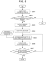
- FIG. 8 shows a flow at the time of planning the system introduction to the customer using the power generation module management device 1.
- each step may be executed by another functional unit.
- step S801 information on the power consumer who is considering introduction of the power generation module is obtained from the communication unit 33 of the power consumer via the communication unit 11 of the power generation module management device 1.
- the information on the power consumer includes the type and output of an asset owned or managed by the consumer.
- information on short-term (units of seconds) and long-term (units of months) change amounts of power demand and power generation change amounts of private power generation facilities is also included.
- the aforementioned asset is a private power generation facility system such as a solar power generation system, a wind power generation system, monogeneration system, or a cogeneration system.
- the power supply information evaluation unit 16 determines the necessity of having a power generation module utilizing RE fuel. For example, in a case where the CO 2 reduction and introduction cost targeted by the customer are satisfied by introducing energy storage equipment such as a battery, it is determined that there is no need for a power generation module utilizing RE fuel. Specifically, in many cases, the battery system can handle power fluctuations in units of seconds to several days.
- the engine performance information calculation unit 15 calculates a required output scale pertaining to the power demanded by the power consumer 3. Also in this calculation, the output scale is calculated in units of seconds to units of months.
- step S804 the engine selection unit 14 selects an available engine.
- distributed engines are divided into RE fuel engines and engines other than the RE fuel engines, a ratio of an output by an engine corresponding to the RE fuel and an output by an engine other than the RE fuel is calculated from the information acquired in step S801 regarding the renewable energy available to the power consumer in each period, and a combination of engines satisfying the respective outputs is selected. There may be a plurality of combinations.
- step S805 the power generation module selection unit 13 refers to the procurable power generation module list 101 to determine the number and types of power generation modules in which the engine selected in step S804 is installed.
- a characteristic item is the type of fuel capable of generating power (corresponding fuel type), and is, for example, the diesel fuel, the spark ignition fuel, or the RE fuel. Although handling of a plurality of compatible fuel types is desirable, a single type is no problem.
- the aged deterioration information is, for example, information regarding changes in the E-SOH at each operation time. Changes in power generation efficiency and outputs at each operation time may be included.
- step S805 of a plurality of power generation modules from the list of power generation modules and the combined provision thereof will now be considered.
- power generation modules capable of handling various types of fuels are selected. Therefore, it is possible to update the modules in accordance with an RE fuel introduction plan of the customer.
- Solar power generation and wind power generation greatly fluctuate from units of seconds to units of months. Therefore, short-period fluctuations in units of seconds or the like are handled by operation control of the modules, and long-period fluctuations such as in units of days to units of months are handled by changing the combination of modules or the number of modules.
- FIGS. 10 to 12 illustrate an example of a module usage plan from an initial introduction stage to a final introduction stage and an example of the handling of monthly fluctuations.
- FIG. 10 illustrates a configuration example in the initial introduction stage
- FIG. 11 illustrates a configuration example in a middle introduction stage
- FIG. 12 illustrates a configuration example in the final introduction stage.
- the initial introduction stage because there are many cases where the amount of renewable energy is small and the amount of available RE fuel is small, the operation is performed mainly using natural gas.
- the ratio of hydrogen in the available fuel is higher than that in other months. This is because the supply of renewable energy such as wind turbines and solar power generation becomes excessive due to the supply and demand balance of power, and the procurement of hydrogen supply utilizing surplus power becomes active.
- the amount of biofuel that can be generated from agricultural waste and plants such as wood is subject to large seasonal variations. In a case where crops and plants are harvested or grown from spring to summer, the crops and plants can then be used as biofuel in autumn. (September to November in FIG. 10 ). In addition, at the initial introduction stage, there are periods when RE power becomes insufficient due to the power demand-supply balance, but in that case, it is possible to operate using only natural gas (January to February and December in FIG. 10 ).
- FIG. 10 shows an example of the fluctuation ranges of 15 to 30 modules.
- the operation rate of the power generation module can be improved.
- the power generation module that is not in use can be deployed to another power consumer or another site of the same power consumer, the power generation module asset can be efficiently operated.
- FIG. 11 is an example of the number and types of power generation modules used in the middle stage of introduction (5 to 10 years after introduction).
- the operation shifts from natural gas being used as the main fuel to RE fuel, that is, hydrogen and biofuel being used as the main fuel. Natural gas is used in periods of insufficient renewable energy (January to March, and December).
- FIG. 12 is an example of the number and types of power generation modules used in the final introduction stage (10 or more years after introduction) .
- the RE fuel is described as hydrogen and biofuel in the present description, ammonia or eFuel, which is a synthetic fuel, may be used.
- eFuel which is a synthetic fuel
- FIGS. 13 and 14 illustrate examples of costs and CO 2 calculation results.
- the costs include the profits of CAPEX, OPEX, and power generation module providers.
- the customer side can determine whether to receive the provision of the power generation modules from the standpoint of whether costs fall within allowable costs.
- FIG. 14 shows the CO 2 discharge amounts predicted as contract years elapse.
- step S807 it is examined in step S807 whether the power consumer aims to reduce CO 2 by 50% after 5 years and to reduce CO 2 by 100% after 10 years, and clears the allowable cost (cost paid by the power consumer) at that time.
- the number and types of power generation modules to be used are selected again in step S805.
- the power generation modules are introduced to the power consumer. Because the information in step S801 is different for each power consumer, the flow of FIG. 8 is performed for each power consumer.
- step S805 the cost and the CO 2 discharge amount are calculated and presented to the power consumer, and hence the power consumer determines whether or not to introduce the power generation modules.
- step S805 the combination of engines satisfying the allowable cost of the power consumer and the target CO 2 discharge amount is selected from the combination of the plurality of engines selected in S804.
- Power can be supplied to a power consumer in a resilient manner. That is, even in periods when it is difficult for the power consumer to procure renewable energy power or in periods when it is difficult to supply RE fuel, power generation including the use of fossil fuel can be performed according to the situation, and hence power can be supplied irrespective of a situation where there are fluctuations in renewable energy. Because the power generation module supplies power by combining a plurality of modules, module replacement can be easily performed while supplying power. In addition, changes according to the situation can be made immediately.
- the power consumer can reduce the CO 2 discharge amount while minimizing the cost. That is, a renewable energy fluctuation state is changed in units of seconds to units of months. Therefore, the amount of renewable energy power generation owned by the power consumer changes, or the type of RE fuel that can be procured changes . Accordingly, the power generation modules yielding the lowest cost and the maximum CO 2 reduction can be selected and recombined.
- the engine, the generator, and the converter, which are components of a power generation module, are mass-produced components that can be used for automobiles and the like, and thus are low-cost components.
- the engine is equipped with an RE handling device, the engine is a mechanism capable of handling RE fuel, fossil fuel, and fuels utilizing a plurality of such fuels, and thus, it is possible to generate power by means of a low-cost power generation module using inexpensive RE fuel and fossil fuel which are procurable.
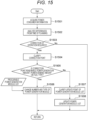
- FIG. 15 is a flowchart illustrating an operation method after the power generation modules are introduced to the power consumer.
- step S1501 the power generation amount data and the fuel consumption amount data of the power consumer, and the health (E s ) of the introduced power generation modules are acquired via the communication unit 11.
- step S1502 the power supply information evaluation unit 16 performs an analysis of the difference between the values of the data and values predicted at the time of planning. Specifically, in a case where the cost or the CO 2 discharge amount illustrated in FIGS. 13 and 14 changes by a predetermined value or more, it is determined that the operation needs to be corrected (step S1503) .
- step S1504 the correction point is clarified in step S1504, and in a case where it is necessary to correct any one of the renewable power generation amount, the power demand amount, and the fuel type of the power consumer in step S1505, the procurable power generation module list 101 is referred to, and the number and type of power generation modules are changed in step S1506. That is, the processing illustrated in FIG. 8 is performed again.
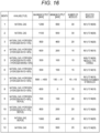
- a case such as that illustrated in FIG. 16 may be considered as the aforementioned update to the power generation module configuration in the middle of operation.
- the maximum value of the hydrogen mixing ratio decreases from 60% to 30% ( May) . Accordingly, the type of the selected modules is changed to a type with which the hydrogen supply ratio is low. Furthermore, for example, a scale may be considered with which the maximum output and the minimum output of the power generation module become smaller than the plan when the amount of renewable power generation owned or managed by the power consumer becomes higher than the plan (July). In this case, the number of modules can be changed.
- step S1507 In a case where it is determined in step S1507 that the correction point is not any of the amount of renewable energy power generation owned by the power consumer, the amount of power demand, and the fuel type, because the cause is the change in the performance of the introduced power generation modules, the updated portion of the database of the power generation module is clarified in step S1507. For example, in a case where the decrease in the E-SOH becomes significant, the maintenance period or the power generation module replacement period due to the deterioration in durability changes, and thus the value of the E-SOH in FIG. 9 is updated. In addition, the values in FIG. 9 are similarly updated in a case where the rated output or the power generation efficiency changes. The aged deterioration information for the power generation module of the same model as the updated module number is updated. Note that the above processing other than step S1506 is executed by, for example, the power supply information evaluation unit 16.
Landscapes
- Business, Economics & Management (AREA)
- Engineering & Computer Science (AREA)
- Human Resources & Organizations (AREA)
- Economics (AREA)
- Strategic Management (AREA)
- General Business, Economics & Management (AREA)
- Entrepreneurship & Innovation (AREA)
- Tourism & Hospitality (AREA)
- Physics & Mathematics (AREA)
- General Physics & Mathematics (AREA)
- Theoretical Computer Science (AREA)
- Marketing (AREA)
- Operations Research (AREA)
- Quality & Reliability (AREA)
- Health & Medical Sciences (AREA)
- Power Engineering (AREA)
- Development Economics (AREA)
- Game Theory and Decision Science (AREA)
- Educational Administration (AREA)
- Public Health (AREA)
- Water Supply & Treatment (AREA)
- General Health & Medical Sciences (AREA)
- Primary Health Care (AREA)
- Supply And Distribution Of Alternating Current (AREA)
- Remote Monitoring And Control Of Power-Distribution Networks (AREA)
- Management, Administration, Business Operations System, And Electronic Commerce (AREA)
Abstract
Description
- The present invention relates to a technology for managing a power generation module having an engine.
- In order to achieve RE (Renewable Energy) 100, which is an international initiative that has been proposed in recent years and that aims to cover 100% of the power consumption of the business operations of a company with renewable energy (hereinafter referred to as "renewable energy"), large-scale introduction of fluctuating renewable energy requires an adjustable power generation system using fuel derived from renewable energy such as hydrogen (hereinafter, RE fuel). Large-scale gas-fired power generation is one option, but the facility investment recovery period is then long.
- In addition, in a case where the output at the time of rated operation of an existing large-scale thermal power generation facility is set at 100%, the range for handling power generation output fluctuations when using the facility is an operation range of 30 to 100%, and thus compatibility with fluctuating renewable energy is low. Further, because the facility installation site is fixed, an examination in combination with power line reinforcement are required, and thus additional asset costs are incurred. Furthermore, because the fuel range to be used in large-scale thermal power generation is limited, it is difficult to flexibly handle existing fuels and RE fuels available in the region. Therefore, in order to shorten the facility investment recovery period, a power generation system capable of handling varying RE fuel through slight improvement of existing assets is required.
- In other words, the provision of an asset service is required that implements flexible power generation utilizing regional RE fuel by adapting existing mass-produced engines such as automobile engines and industrial engines to renewable energy-derived fuels and by using a low-cost engine generator capable of handling fluctuations that combines a plurality of such engines.
- PTL 1:
JP 2018-206302 A - When an automobile or industrial engine is used as a stationary power generation system compatible with RE fuel, the method for using the engine (operating points and operating time) and the method for handling the RE fuel are different, and hence there is a problem of an increase in operating costs due to adaptation at the time of failure or the maintenance cycle being shortened. Therefore, it is important to construct an operation using an appropriate combination of engine types and a replacement method at the time of failure.
- PTL 1 discloses an invention related to a power generation system for which a vehicle engine is repurposed as a stationary engine generator and which combines a plurality of such engine generators. Specifically, an invention is disclosed in which an engine-type power generation device includes a plurality of vehicle engine generators, a fuel supply unit, an operation controller, and a state measuring instrument that measures operation state data of each engine, and in which a management system includes a database unit that stores device information relating to a user and an installation site of the engine-type power generation device, operation state data, and engine information including a specification or a model of the vehicle engine, a data reception unit that receives the operation state data from the engine-type power generation device via a data communication line and stores the operation state data in the database unit, and a replacement-required engine detection unit that, on the basis of the operation state data, detects and specifies that the vehicle engine in a failed state or the like is included in the engine-type power generation device.
-
PTL 1 discloses failure diagnosis after introducing an engine-type power generation device, but does not disclose an examination of the type of power generation device at the time of the introduction. In addition, there are no disclosures relating to the fuel type to be used in handling the RE fuel. For this reason, it is difficult to handle the risk of failure after introducing stationary power generation corresponding to RE fuel and the shortening of the lead times for maintenance and servicing. - In order to solve the above problems, a power generation module management device according to the present invention is a power generation module management device that is used by a power consumer and that manages, according to an amount of power requested by the power consumer, a configuration of power generation sources including at least one power generation module, the device including: a storage unit that records power demand information relating to the amount of power requested by the power consumer and a procurable power generation module list in which procurable power generation modules are recorded, wherein the device selects the power generation module capable of outputting the amount of power requested by the power consumer, from the procurable power generation module list, on a basis of the power demand information and a type of fuel available to the power consumer.
- In the present invention, it is possible to reduce risk of failure, improve ease of servicing and maintenance, and shorten a lead time by selecting an engine generator that can be provided for an energy demand situation of a power consumer and the type of RE fuel that can be used, and by selecting an engine generator according to a state of health of the engine generator. In addition, because the optimal number of devices and the optimal type of devices can be selected according to the energy consumption of the power consumer and the available fuel type, the optimal power can be supplied to the power consumer, and the effective use of the energy resources and the reduction of CO2 can be implemented at low cost.
- Additional features relating to the present invention will become apparent from the description of the present specification and the accompanying drawings. Problems, configurations, advantageous effects, and the like other than those described above will be clarified by the descriptions of the embodiments hereinbelow.
-
- [
FIG. 1] FIG. 1 is a block diagram illustrating a relationship between a power generation module management device and a power consumer according to an embodiment of the present invention. - [
FIG. 2] FIG. 2 is a diagram showing an example of a system configuration in which a diesel engine-based RE handling device is installed. - [
FIG. 3] FIG. 3 is a diagram showing an example of a system configuration in which a spark-ignition engine-based RE handling device is installed. - [
FIG. 4] FIG. 4 is a diagram showing an example of a configuration of a fuel supply device of an RE handling device. - [
FIG. 5] FIG. 5 is a block diagram illustrating a functional configuration of an RE handling device. - [
FIG. 6] FIG. 6 is an example of a graph to illustrate processing performed by a health evaluation unit. - [
FIG. 7] FIG. 7 is another example of a graph to illustrate processing performed by a health evaluation unit. - [
FIG. 8] FIG. 8 is a flowchart showing processing performed at the time of planning introduction of a power generation module to a customer using the power generation module management device. - [
FIG. 9] FIG. 9 is a table showing an example of a procurable power generation module list. - [
FIG. 10] FIG. 10 is a table showing a power generation module configuration at an initial stage of introducing power generation modules. - [
FIG. 11] FIG. 11 is a table showing a power generation module configuration in a middle stage of introducing power generation modules. - [
FIG. 12] FIG. 12 is a table showing a power generation module configuration in a final stage of introducing power generation modules. - [
FIG. 13] FIG. 13 is a graph showing an example of a cost calculated at the time of introducing the power generation modules. - [
FIG. 14] FIG. 14 is a graph showing an example of a CO2 discharge amount calculated at the time of introducing the power generation modules. - [
FIG. 15] FIG. 15 is a flowchart showing an operation method performed by the power generation module management device after introducing the power generation modules. - [
FIG. 16] FIG. 16 is a table showing a situation in which a power generation module configuration is changed during operation. - Hereinafter, an embodiment will be described with reference to the drawings.
-
FIG. 1 is a block diagram to illustrate a relationship between a power generationmodule management device 1 and a power consumer according to an embodiment of the present invention. - The power generation
module management device 1 includes astorage unit 100, determines the required configuration of a power generation module on the basis of, for example,power demand information 103 andoperational information 102 related to an amount of power required by a power consumer such as a factory, and selects power generation modules by referring to the procurable powergeneration module list 101. - The power generation
module management device 1 includes a power supplyinformation evaluation unit 16, an engine performanceinformation calculation unit 15, anengine selection unit 14, a power generationmodule selection unit 13, a cost/CO2 dischargeamount calculation unit 12, and acommunication unit 11. The power generationmodule management device 1 further includes thestorage unit 100. Thestorage unit 100 storespower demand information 103 of a power consumer,operational information 102, and a procurable powergeneration module list 101. The power generationmodule management device 1 selects and determines, on the basis of thepower demand information 103, a configuration of power generation modules to be provided to the power consumer from the procurable powergeneration module list 101. The configuration of power generation modules involves rated outputs of the power generation modules, available fuel types, the required numbers of power generation modules, and the like. The module configuration can be changed on the basis of theoperational information 102 from the module configuration determined at the time of introduction. Because the power generation modules of the present embodiment are small modules, same can be easily replaced, and hence it is possible to provide an optimal power generation module configuration on the basis of the actual power demand of the power consumer. The power consumer is thus able to reduce CO2 at low cost. Although power demand is described as an example of energy demand in the present embodiment, energy demand including heat demand is also included. In addition, the operational information is information on what kind of device or energy source a customer uses in operations, information on the energy use applications, and so forth. - The power generation module management device may be, for example, hardware such as a PC that includes a CPU and a memory, or may be configured to be installed in the cloud as software.
- Hereinafter, each functional unit included in the power generation
module management device 1 will be described. The power supplyinformation evaluation unit 16 acquires the power demand information received from the power consumer and generates information on the power supply capacity required to satisfy the power demand. Because the required power supply information changes depending on the day-to-day weather and the operation status of the customer, the power demand information includes information regarding short-term and long-term change ranges, change times, maximum supplied power, minimum supplied power, and the like. Short term refers to changes in units of seconds, and long term refers to changes in units of months. - The engine performance
information calculation unit 15 calculates requested engine performance information, which is required engine performance information, from the power supply information, and calculates the requested engine performance and the number of engines which are required to constitute the power generation module. - The
engine selection unit 14 collects performance information of distributed engines, and selects an engine on the basis of the requested engine performance information. A criterion for selecting an engine is, for example, an engine model and health (E-SOH (Engine-State Of Health)) . Here, E-SOH (hereinafter referred to as Es) is an index representing the health of the power generation module, and is calculated on the basis of the health and the deterioration state of the engine incorporated in the power generation module. Specifically, the health can be evaluated using any one or more of the timing of the combustion centroid and the combustion stability index. Es at the time of engine procurement is evaluated and acquired under operating conditions such as rotation speed and torque when an engine is incorporated as a power generation module. A plurality of types of engines having different discharge amounts and combustion types may be selected in combination as engines installed in the power generation module. - The power generation
module selection unit 13 selects a power generation module in which an engine selected by theengine selection unit 14 is to be installed, from the procurable powergeneration module list 101. In a case where there is no corresponding power generation module in the list, such a power generation module may be newly manufactured, or theengine selection unit 14 may perform the engine selection again. - The cost/CO2 discharge
amount calculation unit 12 calculates a cost to be charged to the power consumer when the selected power generation module is provided to the power consumer, and a prediction of changes in the CO2 discharge amount due to the operation of the power generation module. As an engine to be incorporated in the power generation module, it is possible to utilize a used vehicle or a used industrial engine, or a brand-new distributed automobile engine or a brand-new distributed industrial engine, and of which the performance, price, and the like are known. When the cost is calculated, the current price of the engine is calculated based on the E-SOH, and the price of the power generation module is determined. When a plurality of power generation modules are combined, a total price of the power generation modules is calculated. In addition, the fuel cost and the maintenance cost at the time of the operation are calculated. As a result, it is possible to calculate the operating expense (OPEX: running cost incurred to run a business) and capital expenditure (CAPEX: investment cost and capital investment, etc.) during the introduction period of the power generation module to be introduced to the power consumer and present the introduction cost (sales price and lease price) to the customer. - The
communication unit 11 of the power generationmodule management device 1 is connected to thecommunication unit 33 of thepower consumer 3 via thenetwork 2, and transmits and receives information such as thepower demand information 103 and theoperational information 102. - The
power generation module 30 of thepower consumer 3 includes anengine 31, a generator/converter 32, and acommunication unit 33 for communicating with the power generationmodule management device 1. As theengine 31, a used or brand-new vehicle engine or a used or brand-new industrial engine is used. AnRE handling device 300 is incorporated in thepower generation module 30 so that the engine can use the RE fuel. Theengine 31 can also use fuel other than renewable energy. It is also possible to supply a plurality of such fuels simultaneously. - As the
engine 31, a diesel engine, a spark-ignition engine, or an HCCI engine (HCCI: Homogeneous-Charge Compression Ignition) can be selected, the selection being made according to the type of available RE fuel. Furthermore, each engine can evaluate the health (Es) of the power generation module via the RE handling device, and can evaluate the durability of the engine, the maintenance lead time, and the like. The health of the generator may also be included in the evaluation. Es will be described below. A plurality of thepower generation modules 30 can be combined, and power generated by a generator is merged by direct current or alternating current and supplied to the power consumer. - The
RE handling device 300 installed in thepower generation module 30 is a device for generating power by means of the power generation module using the RE fuel. TheRE handling device 300 includes anRE fuel tank 301, an REfuel supply device 302, an RE fuelsupply control controller 303, and astorage unit 304. TheRE handling device 300 is connected to theengine 31 by a pipe, and RE fuel is supplied to theengine 31. In addition, data is bidirectionally transmitted between theRE handling device 300 and theengine 31. Further, theRE handling device 300 is connected to thecommunication unit 33 via a signal line, and can transmit data bidirectionally. -
FIG. 2 is a configuration of asystem 4 in which a diesel engine-based RE handling device is installed. The RE fuel is, for example, hydrogen, biogas, ethanol, methanol, ammonia, or the like. In the present embodiment, the REfuel supply device 302 and theRE fuel tank 301 are connected to anintake pipe 44 of anengine combustion chamber 42. The RE fuelsupply control controller 303 is connected to theRE fuel tank 301 and the REfuel supply device 302, a control signal is outputted from the RE fuelsupply control controller 303 to theRE fuel tank 301 and the REfuel supply device 302, and the supply amount and the supply timing of the RE fuel to be supplied to the engine are controlled. A supply amount of RE fuel supplied to the engine is controlled on the basis of a combustion state of the engine and engine operating conditions (rotation speed, torque). The supply amount of RE fuel supplied to the engine may be controlled while the air-fuel ratio is monitored by anairflow sensor 50 and anoxygen concentration sensor 51. The air and the RE fuel are mixed in theintake pipe 44 and supplied to theengine combustion chamber 42. The supplied air and the RE fuel are increased in temperature and pressure by compression of thepiston 41. Thereafter, diesel fuel is supplied from afuel tank 47 to theengine combustion chamber 42 by aninjector 46, combustion is started by ignition of the diesel fuel, and the RE fuel is burned. - A rotation signal of a
rotation sensor 49 of acrankshaft 48 is taken in by the RE fuelsupply control controller 303 to calculate the health Es. In addition, a signal of arotation sensor 53 of the cam shaft is taken into the RE fuelsupply control controller 303, and an engine cylinder determination is performed, and thus the Es of each engine cylinder in the power generation module can be calculated separately. Furthermore, a signal outputted to the REfuel supply device 302 is controlled on the basis of Es, and the supply amount of the RE fuel to be supplied to theengine combustion chamber 42 is controlled, whereby highly efficient combustion can be performed. - The
injector 46 may control the injection amount and the injection timing of the diesel fuel on the basis of the health Es. In addition, the EGR rate, the turbo pressure, the engine speed, and the torque may be controlled. As the diesel fuel, light oil, heavy oil, biodiesel fuel, synthetic fuel, and the like can be used. The synthetic fuel is a hydrocarbon-based fuel synthesized from CO2 and hydrogen, and is, for example, one of the polyoxymethylene dimethyl ethers. - In the present embodiment, configurations corresponding to the RE handling device are the RE fuel
supply control controller 303, theRE fuel tank 301, the REfuel supply device 302, and thestorage unit 304;reference signs reference sign 56 denotes various ECUs installed in the vehicle; and thestorage unit 304 has a function for storing a value calculated by the RE fuelsupply control controller 303. -
FIG. 3 is a diagram showing a configuration of a system 4' in which a spark-ignition engine-based RE handling device is installed. The same configurations as inFIG. 2 are assigned the same reference signs, and descriptions thereof will be omitted. -
FIG. 3 illustrates a configuration in a case where a plurality of fuels are each supplied to theengine combustion chamber 42 by different systems. The REfuel supply device 302 and theRE fuel tank 301 are connected to theintake pipe 44 of theengine combustion chamber 42, and a flow rate of a mixed gas of air and RE fuel is controlled by athrottle 57. The spark ignition fuel is supplied by theinjector 46. The spark ignition fuel is gasoline, LPG, natural gas, ethanol-mixed gasoline, ethanol, or the like. In a case where the RE fuel and the spark ignition fuel are one type or a mixed fuel, the configuration may be any one of theinjector 46 and the REfuel supply device 302. An air-fuel mixture of the supplied fuel and air is supplied to theengine combustion chamber 42, and after piston compression, combustion is started by ignition of anignition device 58. -
FIG. 4 is an example of a configuration of the REfuel supply device 302. As illustrated inFIG. 4 , the REfuel supply device 302 is capable of adjusting and mixing the supply amounts of a plurality of fuels. For example, an injection amount of each of thefuels fuels fuel supply device 302 may use only one injector and may be used for controlling the supply amount of one type of fuel. -
FIG. 5 is a block diagram illustrating a functional configuration of the RE fuelsupply control controller 303. As illustrated inFIG. 5 , input values from various sensors are acquired from asensor input unit 3031. The sensors here include a crankshaft rotation sensor, a camshaft rotation sensor, theairflow sensor 50, theoxygen concentration sensor 51, a current sensor of the generator/converter 32, an engine cylinder pressure sensor, and the like. The input value acquired by thesensor input unit 3031 is transmitted to ahealth evaluation unit 3032, and the health Es is calculated using an equation described below. The calculated Es is further transmitted to acontrol unit 3033, and the REfuel supply device 302, theinjector 46, theignition device 58, thethrottle 57, the EGR valve (not illustrated inFIGS. 2 and3 ), and the generator/converter are controlled on the basis of the health Es. In the generator/converter, power generation operating points (power, voltage, current) are controlled. Thehealth evaluation unit 3032 communicates data with thestorage unit 304. - Processing performed by the engine
health evaluation unit 3032 installed in the RE fuelsupply control controller 303 will be described with reference toFIGS. 6 and7 .FIG. 6 is a graph to illustrate the combustion timing (MFB: Mass Fraction Burnt), and shows the ratio of combustion to the engine rotation timing. The health Es can be evaluated by the combustion timing and the stability of combustion. Here, the combustion ratio is the ratio with which heat is generated by combustion with respect to the amount of heat of the supplied fuel, and the timing with which the ratio becomes 50% is defined as combustion centroid timing (MFB50T) . For example, in a case where impurities are accumulated in the combustion chamber of an engine or when engine oil is likely to be mixed, combustion is performed at an early timing (abnormal combustion on the left side inFIG. 6 ) . On the other hand, if ignitability is poor, or if ignition or flame propagation after ignition is slow, combustion is performed with later timing (abnormal combustion on the right side inFIG. 6 ). The stability of combustion is represented by the variation rate of the indicated mean effective pressure (COV of IMEP), and the lower the variation rate, the higher the combustion stability. The COV is obtained by dividing the standard deviation of the IMEP (a value obtained by dividing the work amount per cycle by the stroke volume of the engine) of each cycle by the average IMEP. The MFB50T and the COV of IMEP are calculated on the basis of data of 10 cycles or more of the engine. -
FIG. 7 is a graph showing the relationships between the fuel type (H2 mixing ratio), the excess air rate and the EGR rate, the combustion timing, and the combustion fluctuation rate. As illustrated inFIG. 7 , because the COV of IMEP and the MFB50T are different depending on the fuel type and conditions (engine speed, torque, excess air rate, EGR rate, and the like) supplied to the engine, a reference point for the operation is determined, and the COV of IMEP and the MFB50T under the reference conditions are periodically calculated to calculate the health Es. Here, the EGR rate is an index indicating the degree of recirculation of the discharge gas, and is represented by (intake CO2 concentration - atmospheric CO2 concentration) / (discharge CO2 concentration - atmospheric CO2 concentration) × 100. - The health Es is calculated using the health Es1 of the timing of the combustion centroid (MFB50T) and the health Es2 of the combustion variation rate (COV of IMEP) . Es1 and Es2 are calculated using
Equation 1.
- a1: Influence coefficient
- Es1: E-SOH (Engine-State of Health) of MFB50T
- Mi: MFB50T of each engine
- Mt: MFB50T reference value
- σ1: Standard deviation of MFB50T of all engines

- a2: Influence coefficient
- Ca: Average value of COV of IMEP
- Ci: COV of IMEP of each engine
- Es2: E-SOH (Engine-State of Health) of COV of IMEP
- σ2: Standard deviation of COV of IMEP of all engines
- Regarding the
above Equation 1, the health Es1 of the MFB50T is calculated from the absolute value of the difference between the MFB50T (Mi) of each engine and the reference value (Mt) of the MFB50T and the standard deviation (σ1) of the MFB50T of all the target engines. Further, the health Es2 of the COV of IMEP is calculated from the difference between the COV of IMEP (Ci) of each engine and the average value (Ca) of the COV of IMEP of all the target engines, and the standard deviation (σ2) of the COV of IMEP of all the target engines. According to the above index, the health Es1 of the MFB50T becomes larger as the value is closer to the reference timing, and thus the normality of the combustion timing can be expressed in a relative manner. Further, the health Es2 of the COV of IMEP enables the combustion stability to be expressed in a relative manner. In Es1 and Es2, the degree of impact can be adjusted by the impact coefficients a1 and a2, respectively, and the degree of impact is set according to the impact on the operation side or the like. - A combustion pressure sensor installed on an engine is used to measure the COV of IMEP and the MFB50T. Furthermore, in an engine in which a pressure sensor is not installed, it is possible to perform estimation using a rotation sensor connected to a crank rotation shaft of the engine, a generated current of a generator connected to the crank rotation shaft, and the like.
-
FIG. 8 shows a flow at the time of planning the system introduction to the customer using the power generationmodule management device 1. Although an example in which each step is executed by any functional unit of power generationmodule management device 1 will be described below, each step may be executed by another functional unit. In step S801, information on the power consumer who is considering introduction of the power generation module is obtained from thecommunication unit 33 of the power consumer via thecommunication unit 11 of the power generationmodule management device 1. The information on the power consumer includes the type and output of an asset owned or managed by the consumer. In addition, information on short-term (units of seconds) and long-term (units of months) change amounts of power demand and power generation change amounts of private power generation facilities is also included. - The aforementioned asset is a private power generation facility system such as a solar power generation system, a wind power generation system, monogeneration system, or a cogeneration system. In step S802, the power supply
information evaluation unit 16 determines the necessity of having a power generation module utilizing RE fuel. For example, in a case where the CO2 reduction and introduction cost targeted by the customer are satisfied by introducing energy storage equipment such as a battery, it is determined that there is no need for a power generation module utilizing RE fuel. Specifically, in many cases, the battery system can handle power fluctuations in units of seconds to several days. In a case where it is determined that the power generation module is required, in step S803, the engine performanceinformation calculation unit 15 calculates a required output scale pertaining to the power demanded by thepower consumer 3. Also in this calculation, the output scale is calculated in units of seconds to units of months. - In step S804, the
engine selection unit 14 selects an available engine. As an example of this selection method, distributed engines are divided into RE fuel engines and engines other than the RE fuel engines, a ratio of an output by an engine corresponding to the RE fuel and an output by an engine other than the RE fuel is calculated from the information acquired in step S801 regarding the renewable energy available to the power consumer in each period, and a combination of engines satisfying the respective outputs is selected. There may be a plurality of combinations. - In step S805, the power generation
module selection unit 13 refers to the procurable powergeneration module list 101 to determine the number and types of power generation modules in which the engine selected in step S804 is installed. - Here, an example of the procurable power generation module list is shown in the table of
FIG. 9 . Characteristics of the power generation modules are listed one by one. A characteristic item is the type of fuel capable of generating power (corresponding fuel type), and is, for example, the diesel fuel, the spark ignition fuel, or the RE fuel. Although handling of a plurality of compatible fuel types is desirable, a single type is no problem. In addition, there are a rated output, a power generation efficiency at the rated time, an output change range (the power generation efficiency is a predetermined value or more), health (Es) of the power generation module, an engine model, a manufacturing year, aged deterioration information, and the like. The aged deterioration information is, for example, information regarding changes in the E-SOH at each operation time. Changes in power generation efficiency and outputs at each operation time may be included. - The selection, in step S805, of a plurality of power generation modules from the list of power generation modules and the combined provision thereof will now be considered. In the present embodiment, power generation modules capable of handling various types of fuels are selected. Therefore, it is possible to update the modules in accordance with an RE fuel introduction plan of the customer. Solar power generation and wind power generation greatly fluctuate from units of seconds to units of months. Therefore, short-period fluctuations in units of seconds or the like are handled by operation control of the modules, and long-period fluctuations such as in units of days to units of months are handled by changing the combination of modules or the number of modules.
- The aforementioned update to the power generation module configuration will be described with reference to
FIGS. 10 to 12. FIGS. 10 to 12 illustrate an example of a module usage plan from an initial introduction stage to a final introduction stage and an example of the handling of monthly fluctuations. Specifically,FIG. 10 illustrates a configuration example in the initial introduction stage,FIG. 11 illustrates a configuration example in a middle introduction stage, andFIG. 12 illustrates a configuration example in the final introduction stage. For example, in the initial introduction stage, because there are many cases where the amount of renewable energy is small and the amount of available RE fuel is small, the operation is performed mainly using natural gas. Further, in May to August inFIG. 10 , the ratio of hydrogen in the available fuel is higher than that in other months. This is because the supply of renewable energy such as wind turbines and solar power generation becomes excessive due to the supply and demand balance of power, and the procurement of hydrogen supply utilizing surplus power becomes active. - Furthermore, the amount of biofuel that can be generated from agricultural waste and plants such as wood is subject to large seasonal variations. In a case where crops and plants are harvested or grown from spring to summer, the crops and plants can then be used as biofuel in autumn. (September to November in
FIG. 10 ). In addition, at the initial introduction stage, there are periods when RE power becomes insufficient due to the power demand-supply balance, but in that case, it is possible to operate using only natural gas (January to February and December inFIG. 10 ). - In addition, customer power demand changes throughout the year. Therefore, the number of modules is adjusted every month. (
FIG. 10 shows an example of the fluctuation ranges of 15 to 30 modules). As a result, the operation rate of the power generation module can be improved. In addition, because the power generation module that is not in use can be deployed to another power consumer or another site of the same power consumer, the power generation module asset can be efficiently operated. - Thereafter, because the amount of RE fuel procured increases from the middle stage to the final stage of introduction, there is a change in the type and amount of available fuel.
FIG. 11 is an example of the number and types of power generation modules used in the middle stage of introduction (5 to 10 years after introduction). In contrast to the initial stage of introduction inFIG. 10 , the operation shifts from natural gas being used as the main fuel to RE fuel, that is, hydrogen and biofuel being used as the main fuel. Natural gas is used in periods of insufficient renewable energy (January to March, and December). -
FIG. 12 is an example of the number and types of power generation modules used in the final introduction stage (10 or more years after introduction) . In this case, only the RE fuel is operated. Although the RE fuel is described as hydrogen and biofuel in the present description, ammonia or eFuel, which is a synthetic fuel, may be used. As described above, by operating the power generation modules while changing the power generation modules in stages in accordance with situations where RE fuel can be introduced, it is possible to seamlessly transition to carbon neutral, and an RE100 implementation can be achieved without difficulty. - The process flow returns to the flowchart of
FIG. 8 again. After determining the number and types of power generation modules to be used in step S805, the cost/CO2 dischargeamount calculation unit 12 performs a calculation of the cost and the CO2 discharge amount in step S806.FIGS. 13 and 14 illustrate examples of costs and CO2 calculation results. As illustrated inFIG. 13 , the costs include the profits of CAPEX, OPEX, and power generation module providers. The customer side can determine whether to receive the provision of the power generation modules from the standpoint of whether costs fall within allowable costs. - In addition,
FIG. 14 shows the CO2 discharge amounts predicted as contract years elapse. For example, it is examined in step S807 whether the power consumer aims to reduce CO2 by 50% after 5 years and to reduce CO2 by 100% after 10 years, and clears the allowable cost (cost paid by the power consumer) at that time. When not cleared, the number and types of power generation modules to be used are selected again in step S805. When the allowable cost and the target CO2 discharge amount are cleared, the power generation modules are introduced to the power consumer. Because the information in step S801 is different for each power consumer, the flow ofFIG. 8 is performed for each power consumer. - As described above, the planning of the power generation module introduction plan illustrated in
FIG. 8 follows a flow in which, after the power generation module configuration is determined in step S805, the cost and the CO2 discharge amount are calculated and presented to the power consumer, and hence the power consumer determines whether or not to introduce the power generation modules. In other words, in step S805, the combination of engines satisfying the allowable cost of the power consumer and the target CO2 discharge amount is selected from the combination of the plurality of engines selected in S804. - The following advantageous effects can be obtained by utilizing the power generation module management device having the above-described functions.
- Power can be supplied to a power consumer in a resilient manner. That is, even in periods when it is difficult for the power consumer to procure renewable energy power or in periods when it is difficult to supply RE fuel, power generation including the use of fossil fuel can be performed according to the situation, and hence power can be supplied irrespective of a situation where there are fluctuations in renewable energy. Because the power generation module supplies power by combining a plurality of modules, module replacement can be easily performed while supplying power. In addition, changes according to the situation can be made immediately.
- It is also possible for the power consumer to reduce the CO2 discharge amount while minimizing the cost. That is, a renewable energy fluctuation state is changed in units of seconds to units of months. Therefore, the amount of renewable energy power generation owned by the power consumer changes, or the type of RE fuel that can be procured changes . Accordingly, the power generation modules yielding the lowest cost and the maximum CO2 reduction can be selected and recombined. The engine, the generator, and the converter, which are components of a power generation module, are mass-produced components that can be used for automobiles and the like, and thus are low-cost components. In addition, because the engine is equipped with an RE handling device, the engine is a mechanism capable of handling RE fuel, fossil fuel, and fuels utilizing a plurality of such fuels, and thus, it is possible to generate power by means of a low-cost power generation module using inexpensive RE fuel and fossil fuel which are procurable.
-
FIG. 15 is a flowchart illustrating an operation method after the power generation modules are introduced to the power consumer. After the power generation module is introduced, in step S1501, the power generation amount data and the fuel consumption amount data of the power consumer, and the health (Es) of the introduced power generation modules are acquired via thecommunication unit 11. In step S1502, the power supplyinformation evaluation unit 16 performs an analysis of the difference between the values of the data and values predicted at the time of planning. Specifically, in a case where the cost or the CO2 discharge amount illustrated inFIGS. 13 and 14 changes by a predetermined value or more, it is determined that the operation needs to be corrected (step S1503) . - In a case where it is necessary to correct the operation, the correction point is clarified in step S1504, and in a case where it is necessary to correct any one of the renewable power generation amount, the power demand amount, and the fuel type of the power consumer in step S1505, the procurable power
generation module list 101 is referred to, and the number and type of power generation modules are changed in step S1506. That is, the processing illustrated inFIG. 8 is performed again. For example, a case such as that illustrated inFIG. 16 may be considered as the aforementioned update to the power generation module configuration in the middle of operation. - For example, in a case where the procurement of hydrogen as RE fuel is less than planned, the maximum value of the hydrogen mixing ratio decreases from 60% to 30% (May) . Accordingly, the type of the selected modules is changed to a type with which the hydrogen supply ratio is low. Furthermore, for example, a scale may be considered with which the maximum output and the minimum output of the power generation module become smaller than the plan when the amount of renewable power generation owned or managed by the power consumer becomes higher than the plan (July). In this case, the number of modules can be changed.
- In a case where it is determined in step S1507 that the correction point is not any of the amount of renewable energy power generation owned by the power consumer, the amount of power demand, and the fuel type, because the cause is the change in the performance of the introduced power generation modules, the updated portion of the database of the power generation module is clarified in step S1507. For example, in a case where the decrease in the E-SOH becomes significant, the maintenance period or the power generation module replacement period due to the deterioration in durability changes, and thus the value of the E-SOH in
FIG. 9 is updated. In addition, the values inFIG. 9 are similarly updated in a case where the rated output or the power generation efficiency changes. The aged deterioration information for the power generation module of the same model as the updated module number is updated. Note that the above processing other than step S1506 is executed by, for example, the power supplyinformation evaluation unit 16. - According to the embodiment of the present invention described above, the following actions and effects are obtained.
- (1) A power generation module management device according to the present invention is a power generation module management device that is used by a power consumer and that manages, according to an amount of power requested by the power consumer, a configuration of power generation sources including at least one power generation module, the device including a storage unit that records power demand information relating to the amount of power requested by the power consumer and a procurable power generation module list in which procurable power generation modules are recorded, wherein the device selects the power generation module capable of outputting the amount of power requested by the power consumer, from the procurable power generation module list, on the basis of the power demand information and a type of fuel available to the power consumer.
According to the above configuration, it is possible to reduce risk of failure, improve ease of servicing and maintenance, and shorten a lead time by selecting an engine generator that can be provided for an energy demand situation of a power consumer and the type of RE fuel that can be used, and by selecting an engine generator (power generation module) according to a health state thereof. In addition, because the optimal number of devices and the optimal type of devices can be selected according to the energy consumption of the power consumer and the type of the available fuel, the optimal power can be supplied to the power consumer, and the effective use of the energy resources and the reduction of CO2 can be implemented at low cost. - (2) The power demand information is information that varies in predetermined periods, and the power generation module management device selects the power generation module in conjunction with the power demand information that varies in the predetermined periods. Accordingly, it is possible to form a power generation module configuration that corresponds to the fuel supply and demand situation which changes every season, thus enabling the power generation modules to be used effectively.
- (3) When the power generation module is to be selected, the power generation module management device calculates a cost to be charged to the power consumer which is generated by introducing the power generation module, and a carbon dioxide discharge amount which is reduced by continuously operating the power generation module. Accordingly, the cost required for implementing the reduction of carbon dioxide discharge amount desired by the consumer can be presented to the power consumer, and it is possible to determine whether or not to introduce the power generation module depending on whether or not the cost falls within the allowable cost for the power consumer.
- (4) Operational information relating to operation of the power generation module is also recorded in the storage unit and, in a case where at least one of the incurred cost and the reduced carbon dioxide discharge amount is dissociated by a predetermined value from the calculated cost or the carbon dioxide discharge amount, the power generation module management device determines whether or not the dissociation is based on a change in the operational information. Accordingly, it is possible to update the power generation module configuration even after the power generation module is introduced, and it is possible to appropriately handle power generation module deterioration or the like caused by operation.
- (5) In a case where the dissociation is based on the change in the operational information, the power generation module is selected again according to the change and, in a case where the dissociation is not based on the change in the operational information, it is determined that the dissociation is based on the change in performance of the power generation module, and the power generation module list is updated on a basis of the change. Accordingly, it is possible to determine whether the power generation module configuration is to be updated in the middle of operation or can be handled only by updating the list.
- (6) The change in performance of the power generation module is a change in any one of health, rated output, and power generation efficiency of the power generation module. Accordingly, the power generation module can be efficiently managed by accumulating, in the list, various pieces of information on the power generation module.
- (7) The health is calculated using either combustion timing or combustion stability when at least one of a power generation output of the power generation module, a type of supply fuel supplied to an engine included in the power generation module, an EGR rate of the engine, and an excess air rate is taken as a criterion. Accordingly, it is possible to appropriately determine the state of the engine by using data that can be easily acquired using a sensor or the like.
- (8) The power generation source includes a plurality of the power generation modules, the plurality of power generation modules being capable of combining generated power by using either a direct current or an alternating current and supplying the combined power, and both a renewable energy-derived fuel and a fossil fuel are suppliable to each of the engines included in the plurality of power generation modules. Accordingly, because various power generation modules and engines can be used, it is possible to provide various options for the power generation module configuration.
- The technical scope of the present invention is not limited to the scope disclosed in the above embodiment, and various modifications are included without departing from the main features of the present invention. Therefore, the above-described embodiment is merely illustrative and should not be interpreted in a limited manner. Moreover, it is possible to add, delete, and replace other configurations with respect to part of the configuration of each embodiment, and all configurations are within the scope of the present invention.
-
- 1 power generation module management device
- 3 power consumer
- 30 power generation module
- 100 storage unit
- 101 procurable power generation module list
- 102 operational information
- 103 power demand information
Claims (8)
- A power generation module management device that is used by a power consumer and that manages, according to an amount of power requested by the power consumer, a configuration of power generation sources including at least one power generation module, the power generation module management device comprisinga storage unit that records power demand information relating to the amount of power requested by the power consumer and a procurable power generation module list in which procurable power generation modules are recorded,wherein the power generation module management device selects the power generation module capable of outputting the amount of power requested by the power consumer, from the procurable power generation module list, on a basis of the power demand information and a type of fuel available to the power consumer.
- The power generation module management device according to claim 1, whereinthe power demand information is information that varies in predetermined periods, andthe power generation module management device selects the power generation module in conjunction with the power demand information that varies in the predetermined periods.
- The power generation module management device according to claim 1, wherein when the power generation module is to be selected, the power generation module management device calculates a cost to be charged to the power consumer which is generated by introducing the power generation module, and a carbon dioxide discharge amount which is reduced by continuously operating the power generation module.
- The power generation module management device according to claim 3, whereinoperational information relating to operation of the power generation module is also recorded in the storage unit, andin a case where at least one of the incurred cost and the reduced carbon dioxide discharge amount is dissociated by a predetermined value from the calculated cost or the carbon dioxide discharge amount, the power generation module management device determines whether or not the dissociation is based on a change in the operational information.
- The power generation module management device according to claim 4, whereinin a case where the dissociation is based on the change in the operational information, the power generation module is selected again according to the change, andin a case where the dissociation is not based on the change in the operational information, it is determined that the dissociation is based on a change in performance of the power generation module, and the procurable power generation module list is updated on a basis of the change.
- The power generation module management device according to claim 5, wherein the change in performance of the power generation module is a change in any one of health, rated output, and power generation efficiency of the power generation module.
- The power generation module management device according to claim 6, wherein the health is calculated using either combustion timing or combustion stability when at least one of a power generation output of the power generation module, a type of supply fuel supplied to an engine included in the power generation module, an EGR rate of the engine, and an excess air rate is taken as a criterion.
- The power generation module management device according to claim 1, whereinthe power generation source includes a plurality of the power generation modules, the plurality of power generation modules being capable of combining generated power by using either a direct current or an alternating current and supplying the combined power, andboth a renewable energy-derived fuel and a fossil fuel are suppliable to each of the engines included in the plurality of power generation modules.
Applications Claiming Priority (2)
| Application Number | Priority Date | Filing Date | Title |
|---|---|---|---|
| JP2022008232A JP7774453B2 (en) | 2022-01-21 | 2022-01-21 | Power generation module management device |
| PCT/JP2022/045677 WO2023139966A1 (en) | 2022-01-21 | 2022-12-12 | Power generation module management device |
Publications (2)
| Publication Number | Publication Date |
|---|---|
| EP4468550A1 true EP4468550A1 (en) | 2024-11-27 |
| EP4468550A4 EP4468550A4 (en) | 2026-01-07 |
Family
ID=87348075
Family Applications (1)
| Application Number | Title | Priority Date | Filing Date |
|---|---|---|---|
| EP22922117.1A Pending EP4468550A4 (en) | 2022-01-21 | 2022-12-12 | DEVICE FOR MANAGING A POWER GENERATION MODULE |
Country Status (3)
| Country | Link |
|---|---|
| EP (1) | EP4468550A4 (en) |
| JP (1) | JP7774453B2 (en) |
| WO (1) | WO2023139966A1 (en) |
Families Citing this family (1)
| Publication number | Priority date | Publication date | Assignee | Title |
|---|---|---|---|---|
| JP2025183055A (en) * | 2024-06-04 | 2025-12-16 | 株式会社日立製作所 | Power generation system |
Family Cites Families (14)
| Publication number | Priority date | Publication date | Assignee | Title |
|---|---|---|---|---|
| JP3787761B2 (en) * | 2001-09-27 | 2006-06-21 | 株式会社日立製作所 | Power generation facility operation planning system and power selling system |
| JP2003193863A (en) | 2001-12-21 | 2003-07-09 | Mitsubishi Heavy Ind Ltd | Evaluation system for gas turbine economic property |
| JP2004085509A (en) * | 2002-08-29 | 2004-03-18 | Mitsubishi Heavy Ind Ltd | Energy cost evaluation system and energy cost evaluation method |
| JP2005085509A (en) | 2003-09-04 | 2005-03-31 | Nec Corp | Fuel cell system and its driving method |
| JP2006004080A (en) | 2004-06-16 | 2006-01-05 | Toshiba Corp | Energy system evaluation system and power generation operation simulator |
| JP4553961B2 (en) * | 2008-01-11 | 2010-09-29 | 中国電力株式会社 | Energy supply system, energy type selection server, and energy supply method |
| JP2011035952A (en) * | 2009-07-29 | 2011-02-17 | Toshiba Corp | Information processor, program, and storage medium |
| JP5992870B2 (en) * | 2013-06-20 | 2016-09-14 | ヤフー株式会社 | Electric power retail management apparatus and electric power retail management method |
| JP2015158750A (en) * | 2014-02-21 | 2015-09-03 | 株式会社東芝 | Power supply operation plan development device, method and program |
| JP6403905B2 (en) * | 2015-12-02 | 2018-10-10 | 三菱電機株式会社 | Power management apparatus, power management system, evaluation method, and program |
| WO2017221411A1 (en) | 2016-06-24 | 2017-12-28 | 三菱電機株式会社 | Control device, power management system, charge/discharge control method, and program |
| JP6923128B2 (en) | 2017-06-09 | 2021-08-18 | 株式会社ルネッサンス・エナジー・リサーチ | A management system that manages the replacement of parts for engine-powered generators |
| JP7089900B2 (en) * | 2018-02-26 | 2022-06-23 | 日立Astemo株式会社 | Internal combustion engine control device and internal combustion engine control method |
| WO2021221847A1 (en) * | 2020-04-28 | 2021-11-04 | Cohn Daniel R | Dispatchable flexible electricity generation for reliable decarbonized grids using multiplexed low-cost engines |
-
2022
- 2022-01-21 JP JP2022008232A patent/JP7774453B2/en active Active
- 2022-12-12 WO PCT/JP2022/045677 patent/WO2023139966A1/en not_active Ceased
- 2022-12-12 EP EP22922117.1A patent/EP4468550A4/en active Pending
Also Published As
| Publication number | Publication date |
|---|---|
| JP7774453B2 (en) | 2025-11-21 |
| WO2023139966A1 (en) | 2023-07-27 |
| EP4468550A4 (en) | 2026-01-07 |
| JP2023107113A (en) | 2023-08-02 |
Similar Documents
| Publication | Publication Date | Title |
|---|---|---|
| US12066850B2 (en) | Energy control and generation method and system | |
| Guandalini et al. | Power-to-gas plants and gas turbines for improved wind energy dispatchability: Energy and economic assessment | |
| Goldstein et al. | Gas-fired distributed energy resource technology characterizations | |
| Strachan et al. | Emissions from distributed vs. centralized generation: The importance of system performance | |
| Kadurek et al. | Electric vehicles and their impact to the electric grid in isolated systems | |
| US11949279B2 (en) | Dispatchable flexible electricity generation for reliable decarbonized grids using multiplexed low-cost engines | |
| Levene et al. | Wind Energy and Production of Hydrogen and Electricity--Opportunities for Renewable Hydrogen | |
| Tappen et al. | Lifetime development and load response of the electrical efficiency of biogas-driven cogeneration units | |
| EP4468550A1 (en) | Power generation module management device | |
| US11339730B2 (en) | Systems and methods for improving fuel economy of internal combustion engines | |
| Wulff et al. | Energy system implications of demand scenarios and supply strategies for renewable transportation fuels | |
| Vasylyev et al. | Best Practices for Electricity Generators and Energy Storage Optimal Dispatch Problems | |
| CN110689188A (en) | Method and device for intelligently optimizing fire coal | |
| Firestone et al. | The value of distributed generation under different tariff structures | |
| Scholz et al. | Increasing flexibility of combined heat and power plants with power-to-heat | |
| Hadley | Emissions benefits of distributed generation in the Texas market | |
| Sachajdak et al. | Performance assessment of using ammonia-fired internal combustion engine cogeneration modules in district heating | |
| KR101871778B1 (en) | Parallel engine generator system and method for controlling the same | |
| Adamowicz et al. | Minimizing Gas-Fired Power Plant Operating Cost and CO2 Emissions With Optimized Scheduling of Gas Turbines and Batteries via Mixed Integer Programming | |
| Counsell et al. | Comparative performance modelling of heat pump based heating systems using dynamic carbon intensity | |
| Wipke et al. | DOE’s National Fuel Cell Vehicle Learning Demonstration Project—NREL’s Data Analysis Results | |
| Hack et al. | Development of rotary engine based Micro-DG/CHP system | |
| Sanvito et al. | Coordinated planning of European charging infrastructure and energy system for optimal V1G and V2G deployment | |
| Galli et al. | An experimentally validated curve-fit model of a hydrogen-fueled internal combustion engine for use in techno-economic analyses | |
| Greff | Comprehensive analysis and improvement of efficiency, emissions and electrical power quality of a small, portable, gasoline-fueled generator system |
Legal Events
| Date | Code | Title | Description |
|---|---|---|---|
| STAA | Information on the status of an ep patent application or granted ep patent |
Free format text: STATUS: THE INTERNATIONAL PUBLICATION HAS BEEN MADE |
|
| PUAI | Public reference made under article 153(3) epc to a published international application that has entered the european phase |
Free format text: ORIGINAL CODE: 0009012 |
|
| STAA | Information on the status of an ep patent application or granted ep patent |
Free format text: STATUS: REQUEST FOR EXAMINATION WAS MADE |
|
| 17P | Request for examination filed |
Effective date: 20240821 |
|
| AK | Designated contracting states |
Kind code of ref document: A1 Designated state(s): AL AT BE BG CH CY CZ DE DK EE ES FI FR GB GR HR HU IE IS IT LI LT LU LV MC ME MK MT NL NO PL PT RO RS SE SI SK SM TR |
|
| DAV | Request for validation of the european patent (deleted) | ||
| DAX | Request for extension of the european patent (deleted) | ||
| A4 | Supplementary search report drawn up and despatched |
Effective date: 20251209 |
|
| RIC1 | Information provided on ipc code assigned before grant |
Ipc: H02J 3/46 20060101AFI20251203BHEP Ipc: G06Q 50/06 20240101ALI20251203BHEP Ipc: H02J 3/38 20060101ALI20251203BHEP Ipc: H02J 13/00 20060101ALI20251203BHEP |