EP4468530A1 - Sealed connector with a retainer integrated to the housing - Google Patents
Sealed connector with a retainer integrated to the housing Download PDFInfo
- Publication number
- EP4468530A1 EP4468530A1 EP23175555.4A EP23175555A EP4468530A1 EP 4468530 A1 EP4468530 A1 EP 4468530A1 EP 23175555 A EP23175555 A EP 23175555A EP 4468530 A1 EP4468530 A1 EP 4468530A1
- Authority
- EP
- European Patent Office
- Prior art keywords
- retainer
- housing
- cable
- retainer parts
- parts
- Prior art date
- Legal status (The legal status is an assumption and is not a legal conclusion. Google has not performed a legal analysis and makes no representation as to the accuracy of the status listed.)
- Pending
Links
Images


Classifications
-
- H—ELECTRICITY
- H01—ELECTRIC ELEMENTS
- H01R—ELECTRICALLY-CONDUCTIVE CONNECTIONS; STRUCTURAL ASSOCIATIONS OF A PLURALITY OF MUTUALLY-INSULATED ELECTRICAL CONNECTING ELEMENTS; COUPLING DEVICES; CURRENT COLLECTORS
- H01R13/00—Details of coupling devices of the kinds covered by groups H01R12/70 or H01R24/00 - H01R33/00
- H01R13/58—Means for relieving strain on wire connection, e.g. cord grip, for avoiding loosening of connections between wires and terminals within a coupling device terminating a cable
- H01R13/582—Means for relieving strain on wire connection, e.g. cord grip, for avoiding loosening of connections between wires and terminals within a coupling device terminating a cable the cable being clamped between assembled parts of the housing
-
- H—ELECTRICITY
- H01—ELECTRIC ELEMENTS
- H01R—ELECTRICALLY-CONDUCTIVE CONNECTIONS; STRUCTURAL ASSOCIATIONS OF A PLURALITY OF MUTUALLY-INSULATED ELECTRICAL CONNECTING ELEMENTS; COUPLING DEVICES; CURRENT COLLECTORS
- H01R13/00—Details of coupling devices of the kinds covered by groups H01R12/70 or H01R24/00 - H01R33/00
- H01R13/58—Means for relieving strain on wire connection, e.g. cord grip, for avoiding loosening of connections between wires and terminals within a coupling device terminating a cable
- H01R13/5804—Means for relieving strain on wire connection, e.g. cord grip, for avoiding loosening of connections between wires and terminals within a coupling device terminating a cable comprising a separate cable clamping part
-
- H—ELECTRICITY
- H01—ELECTRIC ELEMENTS
- H01R—ELECTRICALLY-CONDUCTIVE CONNECTIONS; STRUCTURAL ASSOCIATIONS OF A PLURALITY OF MUTUALLY-INSULATED ELECTRICAL CONNECTING ELEMENTS; COUPLING DEVICES; CURRENT COLLECTORS
- H01R13/00—Details of coupling devices of the kinds covered by groups H01R12/70 or H01R24/00 - H01R33/00
- H01R13/46—Bases; Cases
- H01R13/514—Bases; Cases composed as a modular blocks or assembly, i.e. composed of co-operating parts provided with contact members or holding contact members between them
Definitions
- This disclosure generally relates to the field of automotive interconnections and, for example, to the field of power connectivity for motor vehicles.
- this disclosure relates to a cable connector such as those implemented in power circuits interconnecting inverters, batteries or electrical motors of electric vehicles or plug-in hybrid vehicles.
- Such connectors In power circuits, there are cable connectors electrically linked to cables having a rather large cross section for passing high-intensity-current through.
- Such connectors have a housing with cavities, each configured to accommodate a power terminal.
- Such connectors are usually equipped with seals providing a sealing function between the housing and each cable, to protect the electrical elements from water, moisture, and dust.
- a retainer is usually mounted to the housing to hold each seal into the housing.
- such a retainer may have a strain relief function.
- such a retainer has a passage configured to guide the cable so as to limit adverse deformations of the seal and stress on the terminal.
- such cables may have a relatively high stiffness.
- the cables When there is not much room in the connector environment, the cables must be very curved or bent, which may cause seal deformation and stress on the terminals accommodated in the housing. Such deformation and stress may be detrimental to the connector watertightness and the electrical contact quality between the terminals and those of a counter-connector to which the connector is mated.
- the retainer must be securely attached to the housing.
- Locking means are therefore required on both the retainer and the housing, which are configured to engage with each other to fasten the retainer on the housing.
- each individual retainer 4 may be in the form of a generally cylindrical sleeve with a longitudinal slot 4A.
- Each individual retainer 4 is pre-mounted on each one of the cables 5 intended to be individually electrically connected to a terminal 6, which is itself intended to be accommodated in a cavity 8 of the housing 2.
- the corresponding retainer 4 is moved along the corresponding cable 5 to be clipped onto the housing 2.
- the retainer 4 has wedging means to reduce its internal diameter when inserted into the housing 2. The retainer 4 thus clamps the cable 5 and thus provides a strain-relief function, in addition to its function of holding a seal 7.
- connectors comprising a two-part retainer, configured to retain two cable seals and to provide a cable strain-relief function for two cables at once (see the patent application with the publication number EP 3 662 544 A2 ).
- the two parts of the retainer allows the retainer to be mounted on the housing after the terminals connected to their respective cables have been inserted into the cavities of the housing.
- This disclosure aims at contributing to mitigate at least partially at least one of the above-mentioned drawbacks.
- the retainer parts are integral with the housing, when the retainer is in the open position and in closed position. In other words, they are not supplied as one or several pieces separated from the housing, even if the terminals are not already accommodated in their respective cavities.
- the housing and any part of the retainer are assembled together before being delivered to the harness maker.
- seals and terminals are prepared at the free end of respective cables. For example, the terminals are crimped onto a portion of each seal, as well as, onto a portion of the free end of each cable.
- each terminal connected to a cable is inserted in a cavity.
- the cable is tightened between the retainer parts.
- the retainer has two retainer parts or jaws.
- One of the retainer parts may be made in one piece with the housing, while the other one is slidably mounted on the housing. Alternatively, both parts are slidably mounted on the housing.
- the assembly process of the retainer on the housing is simplified, as is the automation of this process.
- the disclosure below also relates to a method for manufacturing a cable connector, as defined by claim 10.
- Figures. 1 to 6 illustrate an exemplary embodiment of a connector 1.
- the connector 1 comprises a housing 2, a front cover 3, a retainer 4, five cables 5, five terminals 6 and five single wire seals 7.
- the retainer 4 comprises an upper retainer part 41 and a lower retainer part 42.
- the housing 2, the front cover 3 and the upper 41 and lower 42 retainer parts are made of molded plastics.
- the housing 2 comprises five cavities 8.
- the connector 1 comprises more or less than five cavities 8.
- the five cavities 8 are essentially aligned along a transverse direction TD.
- Each cavity 8 is configured to accommodate one terminal 6 mechanically and electrically connected to a cable 5.
- each terminal 6 comprises a crimping portion crimped onto a stripped portion of a cable 5.
- Each terminal 6 is inserted in a respective cavity 8 along an insertion direction ID up to a final position.
- the connector 1 is a straight connector and the housing 2 extends between a rear side 201 and a front side 202 (i.e., mating side), in a longitudinal direction parallel to the insertion direction ID.
- the connector 1 is a right-angle connector.
- Each cable 5 exits from the rear side 201 of the housing, 2 parallel to the insertion direction ID.
- the connector 1 is a female connector accommodating female electrical terminals 6. But this disclosure can be transposed to a male connector (not shown) accommodating male terminals.
- each terminal 6 is an electrical power terminal. But this disclosure can be transposed to an optical connector accommodating optical ferules, each connected to an optical fibre. In such a case, the ferules are the terminals 6 and the optical fibres are the cables 5.
- the terminals 6 are made of a conductive material (e.g., copper or aluminium alloy).
- the housing 2 comprises five sealing portions 9 (See Figure 3 ), each configured to accommodate a seal 7, thereby providing a sealing function between the housing 2 and a cable 5.
- each seal 7 comprises a sealing portion and a fixation portion crimped with a respective terminal 6.
- the terminals 6 are not crimped onto a portion of a seal 7.
- the upper 41 and lower 42 retainer parts are not the same parts. They respectively have a fastening portion 10.
- each fastening portion 10 is essentially centred with respect to the transverse dimension of the retainer part bearing it (this transverse dimension being considered along the transverse direction TD).
- the fastening portion 10 of the upper 41 and lower 42 retainer parts respectively comprises complementary stacking means 10a, 10b which enable a plurality of connectors 1 to be stacked and fastened in a stacking direction SD essentially perpendicular to the insertion ID and the transverse direction TD.
- These complementary stacking means 10a, 10b are not the same. Therefore, the upper 41 and lower 42 retainer parts are different from each other.
- the upper 41 and lower 42 retainer parts may be devoid of the stacking means 10a, 10b and the upper 41 and lower 42 retainer parts may be designed and manufactured as identical parts.
- the upper 41 and lower 42 retainer parts each comprise half strain-relief channels 40 (see Figure 3 ).
- Each half stain-relief channel 40 has an essentially semi-cylindrical inner surface 401 from which protrude two retention teeth 402 see Figure 1 ).
- each essentially semi-cylindrical inner surface 401 of the upper retainer part 41 forms an essentially cylindrical passage with each essentially semi-cylindrical inner surface 401 of the lower retainer part 42.
- Each essentially cylindrical passage guides a cable 5 and the retention teeth 402 protruding in such a passage contributes to a strain-relief function.
- the upper 41 and lower 42 retainer parts each comprise fastening means 11 configured to secure them to the housing 2 (See Figure 3 ).
- these fastening means 11 comprises a guiding leg 12 and a locking leg 13.
- the guiding leg 12 and the locking leg 13 are both flexible.
- the guiding leg 12 and the locking leg 13 extend longitudinally in an actuating direction AD which is essentially parallel to the stacking direction SD.
- the guiding leg 12 and the locking leg 13 extend from a retainer main body 43 to a free end 14.
- the free end 14 of each locking leg 13 is provided with a hook 15. They are both maintained in a guiding slot 16 provided in the housing 2. In the open position of the retainer part which support them, each hook 15 engage a respective notch 17.
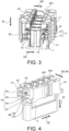
- Each hook 15 and corresponding notch 17 are configured so as to maintain the corresponding retainer part in open position ( Figures 3 and 4 ).
- the open position is also a pre-locked position.
- this retainer part 41 or 42 is pushed towards the housing 2, parallel to the actuating direction AD, up to its closed position. Then, due to slanted surfaces on hooks 15 and/or on the housing 2, the guiding legs 12 flex and the hooks 15 are released from the notches 17.
- the hooks 15 snap back and engage behind a respective slot 16 (Alternatively, the retainer part 41 or 42 is slightly pressed in the insertion direction ID (downwards in Figure 3 ). Then, the guiding legs 12 flex and the hooks 15 are released from the notches 17).
- Each retainer part 41 or 42 also comprises end latching means 18 and intermediate latching means 19.
- the end latching means 18 are respectively provided on a lateral face of the retainer parts 41 or 42, as complementary snap fitting features.
- the end latching means 18 comprises a buckle 44.
- the end latching means 18 comprises a protrusion 45 on the retainer main body 43 and a locking lance 46 with a tooth 47 at the free end of the locking lance 46.
- the buckle 44 co-operates with the protrusion 45, to enhance the retention of the retainer parts 41, 42 together and on the housing 2, but also to enhance the strain relief function.
- the retainer parts 41, 42 are moved from the open position to the closed position, the flexibility of the locking lance 46 helps the tooth 47 to be released from the buckle 44.
- a flange 51 prevents the buckle 44 from coming loose from the protrusion 45.
- the intermediate latching means 19 are located between the end latching means 18.
- they are located on a fastening portion 10.
- the fastening part 10 is strengthened in particular by the presence of the stacking means 10a, 10b, especially when other connectors 1 are attached to it.
- Another advantage of locating the intermediate latching means 19 on a fastening portion 10, is that it allows for more compact stacking of the connectors 1. Indeed, the stacking means 10a or 10b take up space in the stacking direction SD, but as the intermediate latching means 19 are in an operative position only when the retainer 4 is closed, they can be relatively short in the stacking direction SD.
- the intermediate latching means 19 are each provided as two flexible legs 20 extending from an internal surface of each retainer part 41 or 42. This internal surface faces the housing 2.
- a hook 21 extends at the free end of each flexible leg 20.
- the hooks 21 of two adjacent flexible legs 20 of a same intermediate latching means 19 are directed in opposite direction so as to snap fit into an opening 22 made in the housing 2 (see Figure 6 ).
- Advantage is taken from the fact that the cavities 8 have a rear portion with a cylindrical shape to use the room left between these cavities 8 to receive the fastening means 11 and intermediate latching means 19 (see figure 6 ).
- Each retainer part 41 or 42 also comprises guiding means 48 (See Figure 4 ).
- the guiding means 48 are provided as beams 49, each sliding in a respective tunnel 50.
- the guiding means 48 contribute to enhance the rigidity and the reliability of the assembly comprising the housing 2 and the retainer parts 41, 42.
- each terminal 6 is crimped onto a stripped portion of the free end of a cable 5, together with the fixation portion of a single wire seal 7.
- Each terminal 6 thus connected to a cable 5 is inserted in a respective cavity 8, from the rear side 201 of the housing 2. While the retainer parts 41, 42 are in open position, each terminal 6 is inserted in its respective cavity 8 through the rear side 201. Thus, each cable 5 exits the rear side 201 of the housing 2 parallel to the insertion direction ID.
- the retainer parts 41, 42 are in open position, a gap is provided around the cables 5, between each cable 5 and at least one of said retainer parts 41, 42. More precisely, when the retainer parts 41, 42 are in open position, the retention teeth 402 are not clamped onto each cable 5, so that each cable 5 is relatively free to move between said retainer parts 41, 42.
- the retainer parts 41, 42 are moved towards each other from their open position to their closed position.
- the upper retainer part 41 and the lower retainer part 42 are configured so as to be guided by the guiding means 48 and to slide onto the housing 2 from the open position, to the closed position (and vice versa) along an actuating direction AD or closing direction which is parallel to the stacking direction SD and essentially perpendicular to both the insertion direction ID and the transverse direction TD.
- the end latching means 18 are locked together and the intermediate latching means 19 are locked into a respective opening 22 in the housing 2.
- the upper retainer part 41 and the lower retainer part 42 are hold in the closed position, onto the housing, in a final locked position.
- the retainer parts 41, 42 are clamped onto each cable 5.
- the retainer 4 comprising the retainer parts 41, 42, has a strain relief function, in addition to its function of holding the seals 7.
Landscapes
- Connector Housings Or Holding Contact Members (AREA)
Abstract
Cable connector (1) comprising a housing (2), at least one cable (5) exiting from the housing (2), parallel to an insertion direction (ID), at least one terminal (6) accommodated in a cavity (8) of the housing (2), and at least one retainer (4) comprising at least two retainer parts (41, 42). At least one retainer part (41, 42) is movable relative to the other between an open position in which each cable (5) is free to move between said retainer parts (41, 42), and a closed position in which the retainer parts (41, 42) are clamped onto each cable (5). The two retainer parts (41, 42) are integral with the housing (2). At least one of the two retainer parts (41, 42) is configured to slide towards the other retainer part a direction substantially perpendicular to the insertion direction (ID), from the open position to the closed position.
Description
- This disclosure generally relates to the field of automotive interconnections and, for example, to the field of power connectivity for motor vehicles. For example, this disclosure relates to a cable connector such as those implemented in power circuits interconnecting inverters, batteries or electrical motors of electric vehicles or plug-in hybrid vehicles.
- In power circuits, there are cable connectors electrically linked to cables having a rather large cross section for passing high-intensity-current through. Such connectors have a housing with cavities, each configured to accommodate a power terminal. Further, such connectors are usually equipped with seals providing a sealing function between the housing and each cable, to protect the electrical elements from water, moisture, and dust. In addition, a retainer is usually mounted to the housing to hold each seal into the housing. Further, such a retainer may have a strain relief function. For example, such a retainer has a passage configured to guide the cable so as to limit adverse deformations of the seal and stress on the terminal. Indeed, such cables may have a relatively high stiffness. When there is not much room in the connector environment, the cables must be very curved or bent, which may cause seal deformation and stress on the terminals accommodated in the housing. Such deformation and stress may be detrimental to the connector watertightness and the electrical contact quality between the terminals and those of a counter-connector to which the connector is mated.
- In this case, the retainer must be securely attached to the housing. Locking means are therefore required on both the retainer and the housing, which are configured to engage with each other to fasten the retainer on the housing.
- In the prior art, there are
connectors 1 having oneretainer 4 per cable 5 (seeFigure 7 ). In this case, eachindividual retainer 4 may be in the form of a generally cylindrical sleeve with alongitudinal slot 4A. Eachindividual retainer 4 is pre-mounted on each one of thecables 5 intended to be individually electrically connected to aterminal 6, which is itself intended to be accommodated in acavity 8 of thehousing 2. Once theterminal 6 and itsindividual seal 7 are accommodated in thehousing 2, thecorresponding retainer 4 is moved along thecorresponding cable 5 to be clipped onto thehousing 2. Theretainer 4 has wedging means to reduce its internal diameter when inserted into thehousing 2. Theretainer 4 thus clamps thecable 5 and thus provides a strain-relief function, in addition to its function of holding aseal 7. - Such a prior art solution has several drawbacks. For example, the wedging means can damage the outer insulating sheath of the
cables 5. In addition, the individual mounting of eachretainer 4 on a cable and then on thehousing 2 is very time consuming, and does not allow an easy automation. - Also known in the prior art are connectors comprising a two-part retainer, configured to retain two cable seals and to provide a cable strain-relief function for two cables at once (see the patent application with the
publication number EP 3 662 544 A2 ). The two parts of the retainer allows the retainer to be mounted on the housing after the terminals connected to their respective cables have been inserted into the cavities of the housing. - It is common for the assembly of cables, seals and contacts to be carried out by a manufacturer (a so-called "harness maker") different from the one that manufactures the connectors. This often creates a problem in managing the various components (connector housing, retainer, seals, contacts, cables, etc.) in terms of their supply and supply logistics. The more parts there are, the greater the risk of losing or forgetting one.
- This disclosure aims at contributing to mitigate at least partially at least one of the above-mentioned drawbacks.
- To this aim, it is disclosed below a connector according to
claim 1. In the connectors corresponding to the definition ofclaim 1, the retainer parts are integral with the housing, when the retainer is in the open position and in closed position. In other words, they are not supplied as one or several pieces separated from the housing, even if the terminals are not already accommodated in their respective cavities. For example, the housing and any part of the retainer are assembled together before being delivered to the harness maker. Then, at the harness maker facilities, seals and terminals are prepared at the free end of respective cables. For example, the terminals are crimped onto a portion of each seal, as well as, onto a portion of the free end of each cable. In a next step, each terminal connected to a cable is inserted in a cavity. In a further step, the cable is tightened between the retainer parts. In fact, the retainer has two retainer parts or jaws. Advantageously, there are no more than two retainer parts, regardless the number of terminals and cables. Therefore, the number of parts is limited, compared to some prior art retainers. One of the retainer parts may be made in one piece with the housing, while the other one is slidably mounted on the housing. Alternatively, both parts are slidably mounted on the housing. In any case, one can define an open position, in which a gap is provided around the cables between each cable and at least one of said retainer parts, so that each cable can relatively freely be moved between said retainer parts. In any case, the assembly process of the retainer on the housing is simplified, as is the automation of this process. - Other features of this connector are mentioned in the
dependent claims 2 to 9, considered separately from one another, or each one considered in combination to one or several other claims. - The disclosure below also relates to a method for manufacturing a cable connector, as defined by
claim 10. - A connector is disclosed below, by way of one example with reference to the accompanying drawings, in which:
-
FIG. 1 is a schematic perspective view of a connector in accordance with one embodiment, with the retainer in open position; -
FIG. 2 is a schematic perspective view of the connector ofFigure 1 , with a transverse cross-section of its rear portion; -
FIG. 3 is a schematic perspective view, of the rear portion of the connector ofFigures 1 and 2 , with a longitudinal cross-section, -
FIG. 4 is a schematic perspective view of the connector ofFigure 1 to 3 , the retainer being in open position; -
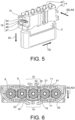
FIG. 5 is a schematic perspective view similar toFigure 4 , the retainer, being in closed position; and -
FIG. 6 is a schematic transversal cross section of the rear portion of the connector ofFigures 1 to 6 ; -
FIG. 7 is a schematic perspective view of a prior art connector. - In this document, the terms "front", "rear", "upper", "lower", "vertical", etc. and derivatives thereof refer to arbitrary orientations as shown on the drawings. However, it is to be understood that various alternative orientations may be used for illustrating this disclosure.
- In the drawings and in the description, same reference numbers are used for the same or similar elements.
-
Figures. 1 to 6 illustrate an exemplary embodiment of aconnector 1. As shown onFigure 1 , theconnector 1 comprises ahousing 2, afront cover 3, aretainer 4, fivecables 5, fiveterminals 6 and fivesingle wire seals 7. - The
retainer 4 comprises anupper retainer part 41 and alower retainer part 42. - The
housing 2, thefront cover 3 and the upper 41 and lower 42 retainer parts are made of molded plastics. - In the illustrated example, the
housing 2 comprises fivecavities 8. In examples of alternative embodiments (not shown), theconnector 1 comprises more or less than fivecavities 8. In this illustrated example, the fivecavities 8 are essentially aligned along a transverse direction TD. Eachcavity 8 is configured to accommodate oneterminal 6 mechanically and electrically connected to acable 5. For example, eachterminal 6 comprises a crimping portion crimped onto a stripped portion of acable 5. Eachterminal 6 is inserted in arespective cavity 8 along an insertion direction ID up to a final position. In the illustrated example, theconnector 1 is a straight connector and thehousing 2 extends between arear side 201 and a front side 202 (i.e., mating side), in a longitudinal direction parallel to the insertion direction ID. In an example of alternative embodiment (not shown), theconnector 1 is a right-angle connector. Eachcable 5 exits from therear side 201 of the housing, 2 parallel to the insertion direction ID. - In the illustrated example, the
connector 1 is a female connector accommodating femaleelectrical terminals 6. But this disclosure can be transposed to a male connector (not shown) accommodating male terminals. - In the illustrated example, each
terminal 6 is an electrical power terminal. But this disclosure can be transposed to an optical connector accommodating optical ferules, each connected to an optical fibre. In such a case, the ferules are theterminals 6 and the optical fibres are thecables 5. - The
terminals 6 are made of a conductive material (e.g., copper or aluminium alloy). - The
housing 2 comprises five sealing portions 9 (SeeFigure 3 ), each configured to accommodate aseal 7, thereby providing a sealing function between thehousing 2 and acable 5. In the example shown (seeFigure 1 ), eachseal 7 comprises a sealing portion and a fixation portion crimped with arespective terminal 6. In an example of alternative embodiment (not shown), theterminals 6 are not crimped onto a portion of aseal 7. - In the illustrated example, the upper 41 and lower 42 retainer parts are not the same parts. They respectively have a
fastening portion 10. For example, eachfastening portion 10 is essentially centred with respect to the transverse dimension of the retainer part bearing it (this transverse dimension being considered along the transverse direction TD). Thefastening portion 10 of the upper 41 and lower 42 retainer parts respectively comprises complementary stackingmeans connectors 1 to be stacked and fastened in a stacking direction SD essentially perpendicular to the insertion ID and the transverse direction TD. These complementary stackingmeans means - The upper 41 and lower 42 retainer parts each comprise half strain-relief channels 40 (see
Figure 3 ). Each half stain-relief channel 40 has an essentially semi-cylindricalinner surface 401 from which protrude tworetention teeth 402 seeFigure 1 ). When the upper 41 and lower 42 retainer parts are in close position, each essentially semi-cylindricalinner surface 401 of theupper retainer part 41 forms an essentially cylindrical passage with each essentially semi-cylindricalinner surface 401 of thelower retainer part 42. Each essentially cylindrical passage guides acable 5 and theretention teeth 402 protruding in such a passage contributes to a strain-relief function. - The upper 41 and lower 42 retainer parts each comprise fastening means 11 configured to secure them to the housing 2 (See
Figure 3 ). For example, these fastening means 11 comprises a guidingleg 12 and a lockingleg 13. The guidingleg 12 and the lockingleg 13 are both flexible. The guidingleg 12 and the lockingleg 13 extend longitudinally in an actuating direction AD which is essentially parallel to the stacking direction SD. The guidingleg 12 and the lockingleg 13 extend from a retainermain body 43 to afree end 14. Thefree end 14 of each lockingleg 13 is provided with ahook 15. They are both maintained in a guidingslot 16 provided in thehousing 2. In the open position of the retainer part which support them, eachhook 15 engage arespective notch 17. Eachhook 15 and correspondingnotch 17 are configured so as to maintain the corresponding retainer part in open position (Figures 3 and 4 ). In other words, the open position is also a pre-locked position. For moving aretainer part retainer part housing 2, parallel to the actuating direction AD, up to its closed position. Then, due to slanted surfaces onhooks 15 and/or on thehousing 2, the guidinglegs 12 flex and thehooks 15 are released from thenotches 17. When theretainer part hooks 15 snap back and engage behind a respective slot 16 (Alternatively, theretainer part Figure 3 ). Then, the guidinglegs 12 flex and thehooks 15 are released from the notches 17). - Each
retainer part retainer parts retainer parts buckle 44. While, on the other one of theretainer parts protrusion 45 on the retainermain body 43 and alocking lance 46 with atooth 47 at the free end of the lockinglance 46. When theretainer parts Figure 4 ), thebuckle 44 co-operates with thetooth 47, to enhance the retention of theretainer parts housing 2. When theretainer parts Figure 4 ), thebuckle 44 co-operates with theprotrusion 45, to enhance the retention of theretainer parts housing 2, but also to enhance the strain relief function. When theretainer parts lance 46 helps thetooth 47 to be released from thebuckle 44. In the closed position of theretainer parts flange 51 prevents thebuckle 44 from coming loose from theprotrusion 45. - The intermediate latching means 19 are located between the end latching means 18. Advantageously, they are located on a
fastening portion 10. In fact, thefastening part 10 is strengthened in particular by the presence of the stackingmeans other connectors 1 are attached to it. Another advantage of locating the intermediate latching means 19 on afastening portion 10, is that it allows for more compact stacking of theconnectors 1. Indeed, the stackingmeans retainer 4 is closed, they can be relatively short in the stacking direction SD. - The intermediate latching means 19 are each provided as two
flexible legs 20 extending from an internal surface of eachretainer part housing 2. Ahook 21 extends at the free end of eachflexible leg 20. Thehooks 21 of two adjacentflexible legs 20 of a same intermediate latching means 19 are directed in opposite direction so as to snap fit into anopening 22 made in the housing 2 (seeFigure 6 ). Advantage is taken from the fact that thecavities 8 have a rear portion with a cylindrical shape to use the room left between thesecavities 8 to receive the fastening means 11 and intermediate latching means 19 (seefigure 6 ). - Each
retainer part Figure 4 ). For example, the guiding means 48 are provided asbeams 49, each sliding in arespective tunnel 50. The guiding means 48 contribute to enhance the rigidity and the reliability of the assembly comprising thehousing 2 and theretainer parts - For assembling the
cable connector 1, the respective free ends ofcables 5 are inserted through a longitudinal central passage of asingle wire seal 7. Then, eachterminal 6 is crimped onto a stripped portion of the free end of acable 5, together with the fixation portion of asingle wire seal 7. Eachterminal 6 thus connected to acable 5 is inserted in arespective cavity 8, from therear side 201 of thehousing 2. While theretainer parts terminal 6 is inserted in itsrespective cavity 8 through therear side 201. Thus, eachcable 5 exits therear side 201 of thehousing 2 parallel to the insertion direction ID. As theretainer parts cables 5, between eachcable 5 and at least one of saidretainer parts retainer parts retention teeth 402 are not clamped onto eachcable 5, so that eachcable 5 is relatively free to move between saidretainer parts - Then the
retainer parts upper retainer part 41 and thelower retainer part 42 are configured so as to be guided by the guiding means 48 and to slide onto thehousing 2 from the open position, to the closed position (and vice versa) along an actuating direction AD or closing direction which is parallel to the stacking direction SD and essentially perpendicular to both the insertion direction ID and the transverse direction TD. - In the closed position, the end latching means 18 are locked together and the intermediate latching means 19 are locked into a
respective opening 22 in thehousing 2. In other words, in the closed position, theupper retainer part 41 and thelower retainer part 42 are hold in the closed position, onto the housing, in a final locked position. In the closed position, or final locked position, theretainer parts cable 5. Thus, theretainer 4, comprising theretainer parts seals 7. - The disclosed solution has several advantages including:
- a reduced assembly time for the harness maker (fewer parts to assemble together),
- simplified operations for the harness maker (only one operation to close the retainer 4),
- an easier automatic assembly,
- less risks of losing parts delivered to the harness maker,
- no risk of forgetting the
retainer 4 during assembly process (as it is already mounted on thehousing 2 delivered to the harness maker), - no risk of damaging the
cables 5 during retainer assembly process (there is no sliding movement of theretainer parts - rework and service operations of the
connector 1 are simplified (for example to replace terminals 6).
Claims (10)
- Cable connector (1) comprising- at least one housing (2) with a rear side (201),- at least one cable (5) exiting from the rear side (201) of the housing (2), parallel to an insertion direction (ID),- at least one terminal (6) which is accommodated in a cavity (8) of the housing (2) and which is mechanically connected to said at least one cable (5),- at least one retainer (4) comprising at least two retainer parts (41, 42), at least one of these two retainer parts (41, 42) being movable relative to the other between an open position in which said at least one cable (5) is free to move between said retainer parts (41, 42), and a closed position in which the retainer parts (41, 42) are clamped onto said at least one cable (5),characterised in that the two retainer parts (41, 42) are integral with the housing (2) when in the open and closed positions, and in that at least one of the two retainer parts (41, 42) is configured to slide towards the other retainer part in an actuating direction (AD), substantially perpendicular to the insertion direction (ID), from the open position to the closed position.
- Cable connector (1) according to claim 1, wherein both retainer parts (41, 42) are slidably mounted on the housing (2) and are respectively configured to slide between the open position and the closed position.
- Cable connector (1) according to claim 1 or 2, wherein each retainer part (41 or 42) comprises at least one half strain-relief channel (40) having an essentially semi-cylindrical inner surface (401) from which protrudes at least one retention tooth (402).
- Cable connector (1) according to claim 3, wherein each retainer part (41 or 42) comprises at least two half strain-relief channels (40).
- Cable connector (1) according to any one of the preceding claims, wherein the two retainer parts (41, 42) each comprises fastening means (11) configured to secure them to the housing (2).
- Cable connector (1) according to claim 5, wherein the fastening means (11) are configured to hold the two retainer parts (41, 42) in a pre-locked position in which each said at least one terminal (6) can be inserted in a cavity (8).
- Cable connector (1) according to any one of the preceding claims, wherein the two retainer parts (41, 42) each comprises end latching means (18) configured to lock the two retainer parts (41, 42) together in closed position.
- Cable connector (1) according to any one of the preceding claims, wherein the two retainer parts (41, 42) each comprises intermediate latching means (19) configured to lock respectively each one of the two retainer parts (41, 42), in locked position, on the housing (2).
- Cable connector (1) according to claim 8, wherein the two retainer parts (41, 42) each comprises a fastening portion (10) comprising stacking means (10a or 10b) configured to fastened another connector (1) in a stacking direction (SD) essentially parallel to the actuating direction (AD), and wherein the intermediate latching means (19) are located on the fastening portion (10).
- A method for assembling a cable connector (1) comprising the following steps:(a) providing a housing (2) having a rear side (201), at least one cavity (8) open on the rear side (201), and a retainer (4) comprising two retainer parts (41, 42) integral with the housing (2),(b) connecting a terminal (6) to a free end of a cable (5),(c) inserting the terminal (6) in the cavity (7), as the two retainer parts (41, 42) are in an open position,(d) moving at least one of the two retainer parts (41, 42) to close the retainer (4) and clamp the cable (5).
Priority Applications (1)
| Application Number | Priority Date | Filing Date | Title |
|---|---|---|---|
| EP23175555.4A EP4468530A1 (en) | 2023-05-26 | 2023-05-26 | Sealed connector with a retainer integrated to the housing |
Applications Claiming Priority (1)
| Application Number | Priority Date | Filing Date | Title |
|---|---|---|---|
| EP23175555.4A EP4468530A1 (en) | 2023-05-26 | 2023-05-26 | Sealed connector with a retainer integrated to the housing |
Publications (1)
| Publication Number | Publication Date |
|---|---|
| EP4468530A1 true EP4468530A1 (en) | 2024-11-27 |
Family
ID=86605244
Family Applications (1)
| Application Number | Title | Priority Date | Filing Date |
|---|---|---|---|
| EP23175555.4A Pending EP4468530A1 (en) | 2023-05-26 | 2023-05-26 | Sealed connector with a retainer integrated to the housing |
Country Status (1)
| Country | Link |
|---|---|
| EP (1) | EP4468530A1 (en) |
Citations (4)
| Publication number | Priority date | Publication date | Assignee | Title |
|---|---|---|---|---|
| US6068522A (en) * | 1997-07-14 | 2000-05-30 | Sumitomo Wiring Systems, Ltd. | Block connector |
| US20170358888A1 (en) * | 2015-04-24 | 2017-12-14 | Kostal Kontakt Systeme Gmbh | Electrical Plug-Type Connector Part |
| EP3662544A1 (en) | 2017-08-01 | 2020-06-10 | Delphi Technologies, LLC | Cable assembly with strain relief |
| EP3849025A1 (en) * | 2020-01-07 | 2021-07-14 | Aptiv Technologies Limited | Hv connector having a rear grid with strain relief means and method for assembling thereof |
-
2023
- 2023-05-26 EP EP23175555.4A patent/EP4468530A1/en active Pending
Patent Citations (4)
| Publication number | Priority date | Publication date | Assignee | Title |
|---|---|---|---|---|
| US6068522A (en) * | 1997-07-14 | 2000-05-30 | Sumitomo Wiring Systems, Ltd. | Block connector |
| US20170358888A1 (en) * | 2015-04-24 | 2017-12-14 | Kostal Kontakt Systeme Gmbh | Electrical Plug-Type Connector Part |
| EP3662544A1 (en) | 2017-08-01 | 2020-06-10 | Delphi Technologies, LLC | Cable assembly with strain relief |
| EP3849025A1 (en) * | 2020-01-07 | 2021-07-14 | Aptiv Technologies Limited | Hv connector having a rear grid with strain relief means and method for assembling thereof |
Similar Documents
| Publication | Publication Date | Title |
|---|---|---|
| EP2686919B1 (en) | High voltage connector assembly | |
| US5411421A (en) | Micropin connector system | |
| KR100624582B1 (en) | Cable interconnection | |
| US9455523B1 (en) | Right angle connection assembly | |
| KR100382174B1 (en) | Electrical connector assembly having a terminal retention system | |
| US5211589A (en) | Micropin connector system | |
| EP1962390B1 (en) | A connector and a connector assembly | |
| JPH08250216A (en) | Electric connector and electric connector assembly including the same | |
| US11749933B2 (en) | Connector | |
| US6129574A (en) | Connector having a construction for preventing an erroneous assembling of a connector housing and a cover | |
| US12046848B2 (en) | Connector having a housing and a mounting member | |
| US5151052A (en) | Micropin connector system | |
| EP0667654B1 (en) | Electrical connector having improved latching/unlatching feature | |
| EP3021423A1 (en) | Electrical connector | |
| EP3849025A1 (en) | Hv connector having a rear grid with strain relief means and method for assembling thereof | |
| EP4468530A1 (en) | Sealed connector with a retainer integrated to the housing | |
| US20240204426A1 (en) | Connector | |
| EP1115191B1 (en) | Connection assembly particularly for the windings of a stator of an electric motor | |
| CN112242626B (en) | Plug connection with tension release | |
| US20250219321A1 (en) | High voltage electrical connector | |
| US12500366B2 (en) | Electrical plug connector and method for assembling an electrical plug connector | |
| US11450985B2 (en) | Connector with integrated seal retainer and secondary terminal lock | |
| EP3866277A1 (en) | Angled connector with a module sliding along a curved path | |
| EP4468528A1 (en) | Sealed connector having a retainer with strain relief means | |
| US11557853B2 (en) | Connector assembly with strain relief device in two parts |
Legal Events
| Date | Code | Title | Description |
|---|---|---|---|
| PUAI | Public reference made under article 153(3) epc to a published international application that has entered the european phase |
Free format text: ORIGINAL CODE: 0009012 |
|
| STAA | Information on the status of an ep patent application or granted ep patent |
Free format text: STATUS: THE APPLICATION HAS BEEN PUBLISHED |
|
| AK | Designated contracting states |
Kind code of ref document: A1 Designated state(s): AL AT BE BG CH CY CZ DE DK EE ES FI FR GB GR HR HU IE IS IT LI LT LU LV MC ME MK MT NL NO PL PT RO RS SE SI SK SM TR |
|
| STAA | Information on the status of an ep patent application or granted ep patent |
Free format text: STATUS: REQUEST FOR EXAMINATION WAS MADE |
|
| 17P | Request for examination filed |
Effective date: 20250523 |