EP4468529A1 - Connector assembly - Google Patents
Connector assembly Download PDFInfo
- Publication number
- EP4468529A1 EP4468529A1 EP22919292.7A EP22919292A EP4468529A1 EP 4468529 A1 EP4468529 A1 EP 4468529A1 EP 22919292 A EP22919292 A EP 22919292A EP 4468529 A1 EP4468529 A1 EP 4468529A1
- Authority
- EP
- European Patent Office
- Prior art keywords
- tubular
- boot
- attachment portion
- wire
- shield shell
- Prior art date
- Legal status (The legal status is an assumption and is not a legal conclusion. Google has not performed a legal analysis and makes no representation as to the accuracy of the status listed.)
- Withdrawn
Links
Images




Classifications
-
- H—ELECTRICITY
- H01—ELECTRIC ELEMENTS
- H01R—ELECTRICALLY-CONDUCTIVE CONNECTIONS; STRUCTURAL ASSOCIATIONS OF A PLURALITY OF MUTUALLY-INSULATED ELECTRICAL CONNECTING ELEMENTS; COUPLING DEVICES; CURRENT COLLECTORS
- H01R13/00—Details of coupling devices of the kinds covered by groups H01R12/70 or H01R24/00 - H01R33/00
- H01R13/58—Means for relieving strain on wire connection, e.g. cord grip, for avoiding loosening of connections between wires and terminals within a coupling device terminating a cable
- H01R13/5804—Means for relieving strain on wire connection, e.g. cord grip, for avoiding loosening of connections between wires and terminals within a coupling device terminating a cable comprising a separate cable clamping part
- H01R13/5812—Means for relieving strain on wire connection, e.g. cord grip, for avoiding loosening of connections between wires and terminals within a coupling device terminating a cable comprising a separate cable clamping part the cable clamping being achieved by mounting the separate part on the housing of the coupling device
-
- H—ELECTRICITY
- H01—ELECTRIC ELEMENTS
- H01R—ELECTRICALLY-CONDUCTIVE CONNECTIONS; STRUCTURAL ASSOCIATIONS OF A PLURALITY OF MUTUALLY-INSULATED ELECTRICAL CONNECTING ELEMENTS; COUPLING DEVICES; CURRENT COLLECTORS
- H01R13/00—Details of coupling devices of the kinds covered by groups H01R12/70 or H01R24/00 - H01R33/00
- H01R13/46—Bases; Cases
- H01R13/52—Dustproof, splashproof, drip-proof, waterproof, or flameproof cases
- H01R13/5205—Sealing means between cable and housing, e.g. grommet
-
- H—ELECTRICITY
- H01—ELECTRIC ELEMENTS
- H01R—ELECTRICALLY-CONDUCTIVE CONNECTIONS; STRUCTURAL ASSOCIATIONS OF A PLURALITY OF MUTUALLY-INSULATED ELECTRICAL CONNECTING ELEMENTS; COUPLING DEVICES; CURRENT COLLECTORS
- H01R13/00—Details of coupling devices of the kinds covered by groups H01R12/70 or H01R24/00 - H01R33/00
- H01R13/648—Protective earth or shield arrangements on coupling devices, e.g. anti-static shielding
- H01R13/658—High frequency shielding arrangements, e.g. against EMI [Electro-Magnetic Interference] or EMP [Electro-Magnetic Pulse]
- H01R13/6591—Specific features or arrangements of connection of shield to conductive members
- H01R13/6592—Specific features or arrangements of connection of shield to conductive members the conductive member being a shielded cable
-
- B—PERFORMING OPERATIONS; TRANSPORTING
- B60—VEHICLES IN GENERAL
- B60R—VEHICLES, VEHICLE FITTINGS, OR VEHICLE PARTS, NOT OTHERWISE PROVIDED FOR
- B60R16/00—Electric or fluid circuits specially adapted for vehicles and not otherwise provided for; Arrangement of elements of electric or fluid circuits specially adapted for vehicles and not otherwise provided for
- B60R16/02—Electric or fluid circuits specially adapted for vehicles and not otherwise provided for; Arrangement of elements of electric or fluid circuits specially adapted for vehicles and not otherwise provided for electric constitutive elements
- B60R16/0207—Wire harnesses
- B60R16/0215—Protecting, fastening and routing means therefor
-
- H—ELECTRICITY
- H01—ELECTRIC ELEMENTS
- H01R—ELECTRICALLY-CONDUCTIVE CONNECTIONS; STRUCTURAL ASSOCIATIONS OF A PLURALITY OF MUTUALLY-INSULATED ELECTRICAL CONNECTING ELEMENTS; COUPLING DEVICES; CURRENT COLLECTORS
- H01R13/00—Details of coupling devices of the kinds covered by groups H01R12/70 or H01R24/00 - H01R33/00
- H01R13/40—Securing contact members in or to a base or case; Insulating of contact members
- H01R13/42—Securing in a demountable manner
- H01R13/422—Securing in resilient one-piece base or case, e.g. by friction; One-piece base or case formed with resilient locking means
- H01R13/4223—Securing in resilient one-piece base or case, e.g. by friction; One-piece base or case formed with resilient locking means comprising integral flexible contact retaining fingers
-
- H—ELECTRICITY
- H01—ELECTRIC ELEMENTS
- H01R—ELECTRICALLY-CONDUCTIVE CONNECTIONS; STRUCTURAL ASSOCIATIONS OF A PLURALITY OF MUTUALLY-INSULATED ELECTRICAL CONNECTING ELEMENTS; COUPLING DEVICES; CURRENT COLLECTORS
- H01R13/00—Details of coupling devices of the kinds covered by groups H01R12/70 or H01R24/00 - H01R33/00
- H01R13/46—Bases; Cases
- H01R13/52—Dustproof, splashproof, drip-proof, waterproof, or flameproof cases
- H01R13/5202—Sealing means between parts of housing or between housing part and a wall, e.g. sealing rings
-
- H—ELECTRICITY
- H01—ELECTRIC ELEMENTS
- H01R—ELECTRICALLY-CONDUCTIVE CONNECTIONS; STRUCTURAL ASSOCIATIONS OF A PLURALITY OF MUTUALLY-INSULATED ELECTRICAL CONNECTING ELEMENTS; COUPLING DEVICES; CURRENT COLLECTORS
- H01R13/00—Details of coupling devices of the kinds covered by groups H01R12/70 or H01R24/00 - H01R33/00
- H01R13/648—Protective earth or shield arrangements on coupling devices, e.g. anti-static shielding
- H01R13/658—High frequency shielding arrangements, e.g. against EMI [Electro-Magnetic Interference] or EMP [Electro-Magnetic Pulse]
- H01R13/6591—Specific features or arrangements of connection of shield to conductive members
- H01R13/65912—Specific features or arrangements of connection of shield to conductive members for shielded multiconductor cable
- H01R13/65914—Connection of shield to additional grounding conductors
-
- H—ELECTRICITY
- H01—ELECTRIC ELEMENTS
- H01R—ELECTRICALLY-CONDUCTIVE CONNECTIONS; STRUCTURAL ASSOCIATIONS OF A PLURALITY OF MUTUALLY-INSULATED ELECTRICAL CONNECTING ELEMENTS; COUPLING DEVICES; CURRENT COLLECTORS
- H01R43/00—Apparatus or processes specially adapted for manufacturing, assembling, maintaining, or repairing of line connectors or current collectors or for joining electric conductors
- H01R43/18—Apparatus or processes specially adapted for manufacturing, assembling, maintaining, or repairing of line connectors or current collectors or for joining electric conductors for manufacturing bases or cases for contact members
Definitions
- the present disclosure relates to a connector assembly.
- a wire harness is used to connect multiple in-vehicle devices.
- the wire harness is electrically connected to the in-vehicle devices via connectors.
- PATENT LITERATURE 1 discloses a connector.
- PATENT LITERATURE 1 Japanese Laid-Open Patent Publication No. 2021-12847
- a connector assembly includes: a connector housing holding a terminal connected to an end portion of an electric wire; a tubular shield shell surrounding the connector housing; a tubular braided wire attached to the shield shell and surrounding the electric wire extending in a first direction from the connector housing; a tubular rubber boot attached to the shield shell and surrounding the braided wire; a first tightening member tightening the rubber boot to the shield shell; and a second tightening member tightening the braided wire to the shield shell, wherein the shield shell has a tubular boot attachment portion for attaching the rubber boot, and a tubular wire attachment portion for attaching the braided wire, the wire attachment portion is provided on the first direction side with respect to the boot attachment portion, the rubber boot has a tubular boot body and an annular sealing portion provided so as to protrude inward in a radial direction from the boot body, and the tubular boot attachment portion has, on an outer peripheral side thereof, a tubular sealing surface with which the sealing portion comes into contact, and
- a connector includes a braided wire surrounding an electric wire extending from a body of the connector and a tubular rubber boot surrounding the braided wire, and can also be referred to as connector assembly.
- FIG. 10 is a cross-sectional view of a conventional connector assembly 100.
- the connector assembly 100 includes a connector housing 101, a tubular shield shell 102 surrounding the connector housing 101, a braided wire 103 attached to the shield shell 102, and a rubber boot 104 attached to the shield shell 102 and surrounding the braided wire 103.
- the connector housing 101 holds a terminal 106 connected to an end portion 105a of an electric wire 105.
- the electric wire 105 is provided so as to extend in a first direction (direction from left to right in FIG. 10 ) from the connector housing 101.
- the braided wire 103 has a tubular shape to surround the electric wire 105.
- the braided wire 103 is fixed to a portion 102a of the shield shell 102 by a caulking ring 110.
- the rubber boot 104 has a tubular boot body 107 and an annular sealing portion 108.
- the shield shell 102 has, on an outer peripheral side thereof, a tubular sealing surface 109 with which the sealing portion 108 comes into contact.
- the caulking ring 110 is composed of a metal member that deforms plastically.
- the caulking ring 110 is provided with a plate portion 111 for retaining the rubber boot 104.
- the sealing portion 108 comes into contact with the plate portion 111 of the caulking ring 110.
- the caulking ring 110 is a member for tightening and fixing the braided wire 103 to the shield shell 102. Therefore, during assembly of the connector assembly 100, the caulking ring 110 is plastically deformed in a direction in which the caulking ring 110 is reduced in diameter.
- FIG. 11 illustrates the caulking ring 110, showing a state after diameter reduction by a solid line and showing a state before diameter reduction by an alternate long and two short dashes line. When the caulking ring 110 is reduced in diameter, an excess length portion is generated at two locations in the circumferential direction as protrusions 113 accordingly.
- the protrusions 113 enlarge outward in the radial direction.
- the sizes of the protrusions 113 are substantially constant, but may vary.
- the rubber boot 104 (see FIG. 10 ) is designed in advance to be larger as a whole, including an allowance, such that the rubber boot 104 does not come into contact with the protrusions 113. Therefore, there is a problem that the connector assembly 101 enlarges in the radial direction.
- the connector assembly can be downsized in the radial direction.
- a connector assembly 10 of the present embodiment shown in FIG. 1 is used in a conductive path for electrically connecting multiple electrical devices.
- electrical devices such as inverters and batteries are installed in a vehicle, such as an electric or hybrid vehicle, for example.
- the electrical devices (in-vehicle devices) are connected via a conductive path for power supply.
- the conductive path includes a wire harness (electric wire) and a connector connected to an end portion of the wire harness.
- the connector assembly 10 of the present embodiment is used as the connector.
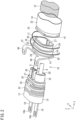
- FIG. 1 is a perspective view showing the connector assembly 10 of the present embodiment.
- FIG. 2 is an exploded perspective view of the connector assembly 10 shown in FIG. 1 .
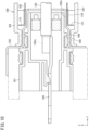
- FIG. 3 is a cross-sectional view of the connector assembly 10 shown in FIG. 1 .
- the connector assembly 10 is attached to a portion of a case 7 (see FIG. 3 ) of the electrical device. Two electric wires 8 are connected to the connector assembly 10. Power is supplied to the electrical device through the electric wires 8 and the connector assembly 10.
- the connector assembly 10 includes a connector housing 11, a shield shell 12, a braided wire 13, a rubber boot 14, a first tightening member 16, and a second tightening member 17.
- the connector assembly 10 (see FIG. 3 ) further includes a retainer 28, an annular sealing member 29, a first rubber ring 33, a second rubber ring 34, and a third rubber ring 35.
- the connector housing 11 holds terminals 18 connected to end portions 21 of the electric wires 8.
- Each terminal 18 is a member that is long in one direction and is made of metal.
- One end portion 18a of the terminal 18 is electrically connected to a mating connector (not shown) of the electrical device.
- Another end portion 18b of the terminal 18 is electrically connected to the electric wire 8.
- Each electric wire 8 is provided so as to extend in a first direction (direction from left to right in FIG. 3 ) from the connector housing 11.
- the direction in which the electric wires 8 are provided so as to extend from the connector housing 11 is defined as “front-rear direction”.
- the one end portion 18a side of the terminals 18 is “front”, and the direction side where the electric wires 8 are provided so as to extend (the right side in FIG. 3 ) is “rear”.
- the two electric wires 8 are provided so as to be aligned (see FIG. 1 and FIG. 2 ).
- the direction in which the two electric wires 8 are aligned is defined as "right-left direction”.
- the direction orthogonal to both the front-rear direction and the right-left direction is defined as "up-down direction”.
- an XYZ rectangular coordinate system is shown.
- the X direction is the right-left direction
- the Y direction is the front-rear direction (direction from front toward rear)
- the Z direction is the up-down direction (direction from bottom toward top).
- One terminal 18 is connected to one electric wire 8.
- the two terminals 18 are provided so as to be aligned in the right-left direction.
- the connector housing 11 and the shield shell 12 each have an oval columnar or tubular shape as a whole. Therefore, the front-rear direction can be referred to as "axial direction”, whereas the right-left direction and the up-down direction orthogonal thereto can be collectively referred to as "radial direction”.
- the connector housing 11 is made of resin.
- the connector housing 11 has a holding portion 31 and a shell attachment portion 32.
- the holding portion 31 has an oval columnar shape having the right-left direction as a major axis direction.
- a space 31a for housing the terminals 18 is provided inside the holding portion 31 (see FIG. 3 ).
- the shell attachment portion 32 has a substantially oval tubular shape having the right-left direction as a major axis direction.
- the holding portion 31 is a portion in which the terminals 18 are housed and held.
- the terminals 18 are fixed to the holding portion 31.
- the shell attachment portion 32 is provided so as to extend rearward (in the Y direction) from the holding portion 31, and is shaped so as to be smaller in the up-down direction and the right-left direction (radial direction) than the holding portion 31.
- the shell attachment portion 32 has a first tubular portion 37 on the front side and a second tubular portion 38 on the rear side.
- the outer periphery of the first tubular portion 37 is provided with an attachment groove 39 to which the third rubber ring 35 is attached.
- the second tubular portion 38 is shaped so as to be smaller in the up-down direction and the right-left direction (radial direction) than the first tubular portion 37.
- the sealing member 29 is an annular member made of rubber, comes into close contact with the outer peripheral surfaces of the electric wires 8, and comes into close contact with the inner peripheral surface of the shell attachment portion 32 (second tubular portion 38). The sealing member 29 prevents foreign matter such as water from entering from between the electric wires 8 and the connector housing 11.
- the retainer 28 is a member made of resin and having holes through which the two electric wires 8 extend.
- the retainer 28 is attached to a rear portion of the shell attachment portion 32 (second tubular portion 38) and prevents the sealing member 29 from falling off rearward.
- the first rubber ring 33 and the second rubber ring 34 are each an annular member made of rubber.
- the first rubber ring 33 and the second rubber ring 34 are attached to the outer peripheral surface of the holding portion 31 so as to be aligned in the front-rear direction.
- the first rubber ring 33 and the second rubber ring 34 come into close contact with attachment holes 7a of the case 7 of the electrical device.
- the first rubber ring 33 and the second rubber ring 34 prevent foreign matter such as water from entering from between the connector housing 11 and the case 7.
- the third rubber ring 35 is an annular member made of rubber.
- the third rubber ring 35 is attached to the outer peripheral surface of the shell attachment portion 32 (first tubular portion 37).
- the third rubber ring 35 comes into close contact with the inner peripheral surface of the shield shell 12 (boot attachment portion 19 described later).
- the third rubber ring 35 prevents foreign matter such as water from entering from between the connector housing 11 and the shield shell 12.
- the shield shell 12 has a tubular body 30 and surrounds the shell attachment portion 32 of the connector housing 11. In addition to the tubular body 30, the shield shell 12 has a flange portion 40 which is attached to the case 7.
- the shield shell 12 is made of metal.
- the shield shell 12 is a cast product.
- the case 7 is made of aluminum, and the shield shell 12 is also made of the same aluminum to prevent electric corrosion caused by dissimilar metal contact.
- FIG. 4 is a cross-sectional view showing a part of the shield shell 12.
- the shield shell 12 has the tubular boot attachment portion 19 for attaching the rubber boot 14, and a tubular wire attachment portion 20 for attaching the braided wire 13.
- the wire attachment portion 20 is provided on the first direction side where the electric wires 8 extend from the connector housing 11, with respect to the boot attachment portion 19. That is, the wire attachment portion 20 is provided on the rear side with respect to the boot attachment portion 19.
- the flange portion 40 is provided on the front side of the boot attachment portion 19.
- the boot attachment portion 19 and the wire attachment portion 20 each have an oval tubular shape having the right-left direction as a major axis direction (see FIG. 2 ).
- the outer periphery and the inner periphery of the wire attachment portion 20 are both shaped so as to be smaller in the up-down direction and the right-left direction than those of the boot attachment portion 19.
- the third rubber ring 35 comes into contact with the inner peripheral surface of the boot attachment portion 19.
- the shield shell 12 is a cast product, and the boot attachment portion 19, the wire attachment portion 20, and the flange portion 40 are integrally molded.
- the braided wire 13 is an electrical conductor formed by braiding wires made of metal (e.g., copper).
- the braided wire 13 is provided along the electric wires 8, has a long tubular shape, and surrounds the electric wires 8.
- the braided wire 13 is attached to the wire attachment portion 20 of the shield shell 12 and is electrically connected to the shield shell 12.
- the braided wire 13 covers the outer peripheral surface of the wire attachment portion 20.
- the braided wire 13 is tightened and fixed to the wire attachment portion 20 by the second tightening member 17 described later. As described above, the braided wire 13 is attached to the shield shell 12 and surrounds the electric wires 8 extending in the first direction from the connector housing 11.
- the braided wire 13, together with the shield shell 12, serves as a shield for the electric wires 8.
- the rubber boot 14 is made of rubber.
- the rubber boot 14 is provided along the braided wire 13, has a long tubular shape, and surrounds the braided wire 13.
- FIG. 1 and FIG. 2 show a state where the rubber boot 14 is cut in the middle.
- the rubber boot 14 is attached to the boot attachment portion 19 of the shield shell 12.
- the rubber boot 14 covers the outer peripheral surface of the boot attachment portion 19.
- the rubber boot 14 is tightened and fixed to the boot attachment portion 19 by the first tightening member 16 described later.
- the rubber boot 14 is attached to the shield shell 12 and surrounds the braided wire 13.
- the rubber boot 14 is provided along the longitudinal direction of the electric wires 8.
- the rubber boot 14 has a tubular boot body 22 surrounding the braided wire 13, and an annular sealing portion 23 (see FIG. 4 ).
- the sealing portion 23 is provided so as to protrude inward in the radial direction of the boot body 22 from an end portion 22a on the front side of the boot body 22.
- the sealing portion 23 has a plurality of annular protrusion-like lip portions 42, and the lip portions 42 come into contact with a sealing surface 24.
- An annular recessed groove 41 is formed on the outer periphery of the end portion 22a of the boot body 22.
- the first tightening member 16 described later is attached to the recessed groove 41.
- the rubber boot 14 is tightened and fixed to the boot attachment portion 19 by the first tightening member 16.
- the first tightening member 16 is a member that tightens the rubber boot 14 to the shield shell 12.
- FIG. 5 is a perspective view of the first tightening member 16.
- the first tightening member 16 has an elongated band-like portion 44 and a tightening portion 45 provided at one end 44a of the band-like portion 44.
- the tightening portion 45 has a locking portion 46.
- the locking portion 46 allows another end 44b of the band-like portion 44 to be inserted therethrough, and prevents the inserted band-like portion 44 from moving in a direction opposite to the insertion direction.
- the locking portion 46 has a claw, and this claw engages a portion of the band-like portion 44, thereby preventing the looped band-like portion 44 from being enlarged in diameter.
- the band-like portion 44 is provided along the outer periphery of the rubber boot 14 fitted externally to the boot attachment portion 19 (see FIG. 4 ).
- the other end 44b of the band-like portion 44 is inserted through the locking portion 46.
- the rubber boot 14 is tightened to the boot attachment portion 19 by the band-like portion 44.
- the first tightening member 16 becomes annular in shape in a state where the rubber boot 14 is tightened.
- the first tightening member 16 may be made of metal such as stainless steel, but in the present embodiment, the first tightening member 16 is made of resin.
- the second tightening member 17 is a member that tightens the braided wire 13 to the shield shell 12.
- FIG. 6 is a perspective view of the second tightening member 17.
- the second tightening member 17 has an elongated band-like portion 47 and a tightening portion 48 provided at one end 47a of the band-like portion 47.
- the tightening portion 48 has a locking portion 49.
- the locking portion 49 allows another end 47b of the band-like portion 47 to be inserted therethrough, and prevents the inserted band-like portion 47 from moving in a direction opposite to the insertion direction.
- the locking portion 49 has a claw, and this claw engages a portion of the band-like portion 47, thereby preventing the looped band-like portion 47 from being enlarged in diameter.
- the band-like portion 47 is provided along the outer periphery of the tubular braided wire 13 provided on the outer periphery of the wire attachment portion 20 (see FIG. 4 ).
- the other end 47b of the band-like portion 47 is inserted through the locking portion 49.
- the braided wire 13 is tightened to the wire attachment portion 20 by the band-like portion 47.
- the second tightening member 17 becomes annular in shape in a state where the braided wire 13 is tightened.
- the second tightening member 17 may be made of resin, but is made of metal such as stainless steel. Since the second tightening member 17 is made of metal, the second tightening member 17 is less likely to be deformed by heat and the tightening force thereof is less likely to be released.
- the boot attachment portion 19 will be further described with reference to FIG. 2 and FIG. 4 .
- the boot attachment portion 19 has a tubular shape, and has the sealing surface 24 and a first protrusion portion 25 on the outer peripheral side thereof.
- the sealing surface 24 is a tubular surface, and the sealing portion 23 of the rubber boot 14 comes into contact therewith.
- the sealing portion 23 is brought into contact with the sealing surface 24 while being pressed against the sealing surface 24 by the first tightening member 16.
- the first protrusion portion 25 protrudes outward in the radial direction of the boot attachment portion 19 from a portion (end portion) on the rear side of the sealing surface 24.
- a distal end 25a of the first protrusion portion 25 is located outward of the sealing surface 24 in the radial direction.
- the first protrusion portion 25 is provided over the entire circumference of the boot attachment portion 19.
- the boot attachment portion 19 further has an annular portion 51.
- the annular portion 51 is provided so as to protrude outward in the radial direction of the boot attachment portion 19 from a portion (end portion) on the front side of the sealing surface 24.
- the flange portion 40 is connected to both side portions in the right-left direction of the annular portion 51.
- the boot attachment portion 19 has, on the inner peripheral side thereof, a contact surface with which the third rubber ring 35 comes into contact.
- the sealing surface 24 has a linear shape parallel to a straight line in the front-rear direction.
- an inner peripheral surface 55 of the boot attachment portion 19 has a linear shape inclined with respect to a straight line in the front-rear direction. That is, the boot attachment portion 19 has, in the inner peripheral surface 55 thereof, a first inclined surface 53 reduced in diameter from the front toward the rear. Therefore, the boot attachment portion 19 is formed such that a thickness dimension in the radial direction thereof decreases from the rear toward the front.
- the first inclined surface 53 is a contact surface for the third rubber ring 35.
- the wire attachment portion 20 will be further described with reference to FIG. 2 and FIG. 4 .
- the wire attachment portion 20 has a tubular shape, and has an electrical connection surface 26 on the outer peripheral side thereof.
- the electrical connection surface 26 is a tubular surface and is electrically connected to the braided wire 13. A portion of the braided wire 13 is brought into contact with the electrical connection surface 26 while being tightened to the electrical connection surface 26 by the second tightening member 17.
- the wire attachment portion 20 is shaped so as to be smaller in the up-down direction and the right-left direction than the boot attachment portion 19. Therefore, the electrical connection surface 26 is provided inward of the sealing surface 24 in the radial direction.
- the wire attachment portion 20 has a second protrusion portion 27 on the outer peripheral side thereof.
- the second protrusion portion 27 protrudes outward in the radial direction of the wire attachment portion 20 from a portion (end portion) on the rear side of the electrical connection surface 26.
- a distal end 27a of the second protrusion portion 27 is located outward of the electrical connection surface 26 in the radial direction.
- the second protrusion portion 27 is provided over the entire circumference of the wire attachment portion 20. As shown in FIG. 4 , the distal end 27a of the second protrusion portion 27 is located inward of the distal end 25a of the first protrusion portion 25 in the radial direction. Furthermore, in the present embodiment, the distal end 27a of the second protrusion portion 27 is located inward of the sealing surface 24 in the radial direction.
- the inner peripheral surface (first inner peripheral surface 54) of the wire attachment portion 20 is shaped so as to be smaller in the up-down direction and the right-left direction (radial direction) than the inner peripheral surface (second inner peripheral surface 55) of the boot attachment portion 19. Therefore, an annular wall surface 56 is provided between the first inner peripheral surface 54 and the second inner peripheral surface 55 (see FIG. 4 ).
- the wall surface 56 is an annular surface that faces frontward.
- the electrical connection surface 26 has a linear shape parallel to a straight line in the front-rear direction.
- the inner peripheral surface 54 of the wire attachment portion 20 has a linear shape inclined with respect to a straight line in the front-rear direction. That is, the wire attachment portion 20 has, in the inner peripheral surface 54 thereof, a second inclined surface 58 enlarged in diameter from the front toward the rear. Therefore, the wire attachment portion 20 is formed such that a thickness dimension in the radial direction thereof decreases from the front toward the rear.
- FIG. 7 shows schematic diagrams of the boot attachment portion 19 and the wire attachment portion 20.
- the boot attachment portion 19 has, on the inner peripheral side thereof, the first inclined surface 53 reduced in diameter toward the rear direction.
- the wire attachment portion 20 has, on the inner peripheral side thereof, the second inclined surface 58 enlarged in diameter toward the rear direction.
- the inclination angles of the wire attachment portion 20 and the boot attachment portion 19 on the inner peripheral side are shown larger than actual ones.
- the shield shell 12 is produced by casting.
- a split mold for forming the inner peripheral surface of the shield shell 12 moves in the axial direction. Since the shield shell 12 has the first inclined surface 53 and the second inclined surface 58, demolding is facilitated.
- the diagram (B) shown on the right side of FIG. 7 shows a modification.
- the boot attachment portion 19 has, on the inner peripheral side thereof, the first inclined surface 53 reduced in diameter toward the rear direction.
- the modification is the same as the present embodiment shown in the diagram (A) on the left side of FIG. 7 .
- the wire attachment portion 20 has, on the inner peripheral side thereof, the second inclined surface 58 reduced in diameter toward the rear direction. That is, the direction of inclination of the inner peripheral side of the wire attachment portion 20 is opposite between the present embodiment and the modification.
- the dimension in the radial direction (inner diameter) of the first tubular portion 37 is the same in the present embodiment shown in the diagram (A) of FIG. 7 and in the modification shown in the diagram (B) of FIG. 7 .
- the inner peripheral surface of the shield shell 12 as a whole becomes larger in the radial direction from the rear side toward the front side. That is, with a rear end 12e of the shield shell 12 as a starting point, the inner peripheral surface of the shield shell 12 becomes larger in the radial direction from the rear end 12e toward a front end 12f. Therefore, the dimension in the radial direction from the rear end 12e to the front end 12f becomes larger. As a result, the shield shell 12 becomes thicker in the radial direction.
- the shield shell 12 becomes thinner in the radial direction, and the connector assembly 10 including the rubber boot 14 can be made smaller in the radial direction.
- the dimension difference in the radial direction of an outer surface 14a of the rubber boot 14 between the modification and the present embodiment is indicated as "Q" in FIG. 7 .
- the size is smaller in the radial direction than in the modification by the dimension Q.
- the connector assembly 10 of the present embodiment includes the connector housing 11, the tubular shield shell 12 surrounding the connector housing 11, the tubular braided wire 13 attached to the shield shell 12, the tubular rubber boot 14 attached to the shield shell 12, the first tightening member 16 tightening the rubber boot 14 to the shield shell 12, and the second tightening member 17 tightening the braided wire 13 to the shield shell 12.
- the connector housing 11 holds the terminals 18 connected to the end portions 21 of the electric wires 8.
- the braided wire 13 surrounds the electric wires 8 extending rearward from the connector housing 11.
- the rubber boot 14 surrounds the braided wire 13.
- the shield shell 12 has the tubular boot attachment portion 19 for attaching the rubber boot 14, and the tubular wire attachment portion 20 for attaching the braided wire 13.
- the wire attachment portion 20 is provided on the rear side with respect to the boot attachment portion 19.
- the rubber boot 14 has the tubular boot body 22 and the annular sealing portion 23.
- the sealing portion 23 is provided so as to protrude inward in the radial direction from the boot body 22.
- the tubular boot attachment portion 19 has, on the outer peripheral side thereof, the tubular sealing surface 24 with which the sealing portion 23 comes into contact, and the first protrusion portion 25.
- the first protrusion portion 25 protrudes outward in the radial direction from the portion on the rear side of the sealing surface 24.
- the first protrusion portion 25 can prevent the rubber boot 14 from falling off rearward.
- the first protrusion portion 25 is provided on the shield shell 12, and can be designed such that the rubber boot 14 does not interfere with the first protrusion portion 25. That is, the rubber boot 14 no longer needs to be designed to be large, including an allowance, as in the conventional art.
- the connector assembly 10 can be downsized in the radial direction.
- the shield shell 12 has the tubular wire attachment portion 20.
- the tubular wire attachment portion 20 has, on the outer peripheral side thereof, the tubular electrical connection surface 26 electrically connected to the braided wire 13.
- the electrical connection surface 26 is provided inward of the sealing surface 24 in the radial direction.
- the wire attachment portion 20 is smaller in the radial direction than the boot attachment portion 19. Therefore, the boot body 22 surrounding the braided wire 13 attached to the wire attachment portion 20 can be smaller in the radial direction. As a result, the connector assembly 10 can be downsized in the radial direction.
- FIG. 8 shows cross-sectional views each showing a part of the connector assembly 10.
- (A) on the left side and (B) at the center show Modification 2 and Modification 3, respectively, and (C) on the right side shows the present embodiment.
- no third rubber ring 35 is provided in Modification 2 shown in (A).
- a sealing function to prevent entry of water is low.
- the sealing function is enhanced by the provision of the third rubber ring 35, but the dimension in the radial direction is larger than in Modification 2 shown in (A). Therefore, in the present embodiment shown in (C), even though the third rubber ring 35 is provided, the wire attachment portion 20 is smaller in the radial direction than the boot attachment portion 19. Therefore, in the present embodiment, the connector assembly 10 can be downsized in the radial direction.
- the wire attachment portion 20 further has the second protrusion portion 27 protruding outward in the radial direction from the portion on the rear side of the electrical connection surface 26.
- the second protrusion portion 27 can prevent the braided wire 13 from falling off rearward.
- the distal end 27a of the second protrusion portion 27 is located inward of the distal end 25a of the first protrusion portion 25 in the radial direction. Therefore, the wire attachment portion 20 as a whole is smaller in the radial direction than the boot attachment portion 19.
- the distal end 27a of the second protrusion portion 27 is located inward of the sealing surface 24 in the radial direction. Therefore, the wire attachment portion 20 becomes even smaller in the radial direction.
- the boot body 22 can be made smaller in the radial direction, contributing to downsizing the connector assembly 10.
- the first protrusion portion 25 is provided over the entire circumference of the boot attachment portion 19. Therefore, the function of preventing the rubber boot 14 from falling off is enhanced.
- the second protrusion portion 27 is provided over the entire circumference of the wire attachment portion 20. Therefore, the function of preventing the braided wire 13 from falling off is enhanced.
- FIG. 9 is a cross-sectional view of a portion where the braided wire 13 is attached by the second tightening member 17.
- FIG. 9 shows a cross-section orthogonal to the front-rear direction.
- the second tightening member 17 has the elongated band-like portion 47 and the tightening portion 48 provided at the one end 47a of the band-like portion 47.
- the tightening portion 48 protrudes outward in the radial direction from the band-like portion 47. Therefore, in the present embodiment, a housing portion 63 for housing the tightening portion 48 is provided at a portion in the circumferential direction of the boot body 22 such that the tightening portion 48 does not interfere with the inner peripheral surface of the rubber boot 14.
- the boot body 22 has a tubular portion 61 having a smooth inner surface 62, and the housing portion 63 provided at the portion in the circumferential direction of the boot body 22.
- the smooth inner surface 62 has an oval tubular shape having the right-left direction as a major axis direction.
- an inner surface 64 thereof is located outward of the inner surface 62 of the tubular portion 61 in the radial direction. That is, at the portion (housing portion 63) of the boot body 42, the inner surface thereof bulges outward in the radial direction.
- the entire housing portion 63 bulges outward in the radial direction.
- the tightening portion 48 of the second tightening member 17 is housed at the housing portion 63. Therefore, it is only necessary to provide the housing portion 63 for housing the tightening portion 48 of the second tightening member 17, at the portion in the circumferential direction of the boot body 22, and the entire size of the boot body 22 does not need to be unnecessarily increased.
- the connector assembly 10 can be downsized in the radial direction.
- first protrusion portion 25 and the second protrusion portion 27 are provided over the entire circumference, but portions in the circumferential direction of the first protrusion portion 25 and the second protrusion portion 27 may be omitted.
- the first tightening member 16 and the second tightening member 17 may be made of materials other than those described above, and may be in forms other than those illustrated.
Landscapes
- Connector Housings Or Holding Contact Members (AREA)
- Details Of Connecting Devices For Male And Female Coupling (AREA)
Abstract
Description
- The present disclosure relates to a connector assembly.
- This application claims priority on
Japanese Patent Application No. 2022-004967 filed on January 17, 2022 - For example, in a vehicle such as an electric or hybrid vehicle, a wire harness is used to connect multiple in-vehicle devices. The wire harness is electrically connected to the in-vehicle devices via connectors. PATENT LITERATURE 1 discloses a connector.
- PATENT LITERATURE 1:
Japanese Laid-Open Patent Publication No. 2021-12847 - A connector assembly according to an aspect of the present disclosure includes: a connector housing holding a terminal connected to an end portion of an electric wire; a tubular shield shell surrounding the connector housing; a tubular braided wire attached to the shield shell and surrounding the electric wire extending in a first direction from the connector housing; a tubular rubber boot attached to the shield shell and surrounding the braided wire; a first tightening member tightening the rubber boot to the shield shell; and a second tightening member tightening the braided wire to the shield shell, wherein the shield shell has a tubular boot attachment portion for attaching the rubber boot, and a tubular wire attachment portion for attaching the braided wire, the wire attachment portion is provided on the first direction side with respect to the boot attachment portion, the rubber boot has a tubular boot body and an annular sealing portion provided so as to protrude inward in a radial direction from the boot body, and the tubular boot attachment portion has, on an outer peripheral side thereof, a tubular sealing surface with which the sealing portion comes into contact, and a first protrusion portion protruding outward in the radial direction from a portion on the first direction side of the sealing surface.
-
-
FIG. 1 is a perspective view showing a connector assembly of an embodiment. -
FIG. 2 is an exploded perspective view of the connector assembly shown inFIG. 1 . -
FIG. 3 is a cross-sectional view of the connector assembly shown inFIG. 1 . -
FIG. 4 is a cross-sectional view showing a part of a shield shell. -
FIG. 5 is a perspective view of a first tightening member. -
FIG. 6 is a perspective view of a second tightening member. -
FIG. 7 shows schematic diagrams of a boot attachment portion and a wire attachment portion. -
FIG. 8 shows cross-sectional views each showing a part of the connector assembly. -
FIG. 9 is a cross-sectional view of a portion where a braided wire is attached by the second tightening member. -
FIG. 10 is a cross-sectional view of a conventional connector assembly. -
FIG. 11 illustrates a conventional caulking ring. - A connector includes a braided wire surrounding an electric wire extending from a body of the connector and a tubular rubber boot surrounding the braided wire, and can also be referred to as connector assembly.
FIG. 10 is a cross-sectional view of aconventional connector assembly 100. Theconnector assembly 100 includes aconnector housing 101, atubular shield shell 102 surrounding theconnector housing 101, a braidedwire 103 attached to theshield shell 102, and arubber boot 104 attached to theshield shell 102 and surrounding the braidedwire 103. Theconnector housing 101 holds aterminal 106 connected to anend portion 105a of anelectric wire 105. - The
electric wire 105 is provided so as to extend in a first direction (direction from left to right inFIG. 10 ) from theconnector housing 101. The braidedwire 103 has a tubular shape to surround theelectric wire 105. The braidedwire 103 is fixed to aportion 102a of theshield shell 102 by acaulking ring 110. Therubber boot 104 has atubular boot body 107 and anannular sealing portion 108. Theshield shell 102 has, on an outer peripheral side thereof, atubular sealing surface 109 with which the sealingportion 108 comes into contact. - The
caulking ring 110 is composed of a metal member that deforms plastically. In theconnector assembly 100 shown inFIG. 10 , thecaulking ring 110 is provided with aplate portion 111 for retaining therubber boot 104. When therubber boot 104 tries to come out in the first direction, thesealing portion 108 comes into contact with theplate portion 111 of thecaulking ring 110. - The
caulking ring 110 is a member for tightening and fixing the braidedwire 103 to theshield shell 102. Therefore, during assembly of theconnector assembly 100, thecaulking ring 110 is plastically deformed in a direction in which thecaulking ring 110 is reduced in diameter.FIG. 11 illustrates thecaulking ring 110, showing a state after diameter reduction by a solid line and showing a state before diameter reduction by an alternate long and two short dashes line. When thecaulking ring 110 is reduced in diameter, an excess length portion is generated at two locations in the circumferential direction asprotrusions 113 accordingly. - The
protrusions 113 enlarge outward in the radial direction. The sizes of theprotrusions 113 are substantially constant, but may vary. In consideration of this variation, the rubber boot 104 (seeFIG. 10 ) is designed in advance to be larger as a whole, including an allowance, such that therubber boot 104 does not come into contact with theprotrusions 113. Therefore, there is a problem that theconnector assembly 101 enlarges in the radial direction. - According to the present disclosure, the connector assembly can be downsized in the radial direction.
- <Outline of embodiment of the present disclosure>
- Hereinafter, the outline of an embodiment of the present disclosure will be listed and described.
- (1) A connector assembly of the present embodiment includes: a connector housing holding a terminal connected to an end portion of an electric wire; a tubular shield shell surrounding the connector housing; a tubular braided wire attached to the shield shell and surrounding the electric wire extending in a first direction from the connector housing; a tubular rubber boot attached to the shield shell and surrounding the braided wire; a first tightening member tightening the rubber boot to the shield shell; and a second tightening member tightening the braided wire to the shield shell, wherein the shield shell has a tubular boot attachment portion for attaching the rubber boot, and a tubular wire attachment portion for attaching the braided wire, the wire attachment portion is provided on the first direction side with respect to the boot attachment portion, the rubber boot has a tubular boot body and an annular sealing portion provided so as to protrude inward in a radial direction from the boot body, and the tubular boot attachment portion has, on an outer peripheral side thereof, a tubular sealing surface with which the sealing portion comes into contact, and a first protrusion portion protruding outward in the radial direction from a portion on the first direction side of the sealing surface.
In the connector assembly of the present embodiment, the first protrusion portion can prevent the rubber boot from falling off in the first direction. The first protrusion portion is provided on the shield shell, and can be designed such that the rubber boot does not interfere with the first protrusion portion. That is, the rubber boot no longer needs to be designed to be large, including an allowance, as in the conventional art, so that the connector assembly can be downsized in the radial direction. - (2) Preferably, the tubular wire attachment portion has, on an outer peripheral side thereof, a tubular electrical connection surface electrically connected to the braided wire, the wire attachment portion has a second protrusion portion protruding outward in the radial direction from a portion on the first direction side of the electrical connection surface, and a distal end of the second protrusion portion is located inward of a distal end of the first protrusion portion in the radial direction. In this case, the second protrusion portion can prevent the braided wire from falling off in the first direction. The wire attachment portion as a whole is smaller in the radial direction than the boot attachment portion. As a result, the boot body can be made smaller in the radial direction, contributing to downsizing the connector assembly.
- (3) In the connector assembly of (2) above, further preferably, the distal end of the second protrusion portion is located inward of the sealing surface in the radial direction. In this case, the wire attachment portion becomes even smaller in the radial direction.
- (4) Preferably, the second protrusion portion is provided over an entire circumference of the wire attachment portion. In this case, the function of preventing the braided wire from falling off is enhanced.
- (5) Preferably, the first protrusion portion is provided over an entire circumference of the boot attachment portion. In this case, the function of preventing the rubber boot from falling off is enhanced.
- (6) Preferably, the second tightening member has a band-like portion provided along an outer periphery of the tubular braided wire, and a tightening portion provided at one end of the band-like portion, and the tightening portion has a locking portion allowing another end of the band-like portion to be inserted therethrough and preventing the inserted band-like portion from moving in a direction opposite to an insertion direction.
- (7) In the connector assembly of (6) above, preferably, the boot body has a tubular portion having a smooth inner surface, and a housing portion provided at a portion in a circumferential direction of the boot body and having an inner surface located outward of the tubular portion in the radial direction, and the tightening portion is housed at the housing portion. In this case, it is only necessary to provide the housing portion for housing the tightening portion of the second tightening member, at the portion in the circumferential direction of the boot body, and the entire size of the boot body does not need to be unnecessarily increased.
- (8) Preferably, the boot attachment portion has, on an inner peripheral side thereof, a first inclined surface reduced in diameter toward the first direction, and the wire attachment portion has, on an inner peripheral side thereof, a second inclined surface enlarged in diameter toward the first direction. In this case, the overall dimensions in the radial direction of the boot attachment portion and the wire attachment portion can be made smaller than in the case where the second inclined surface of the wire attachment portion is reduced in diameter toward the first direction.
- Hereinafter, the details of an embodiment of the present disclosure will be described with reference to the drawings. At least parts of the embodiment described below may be combined as desired.
- A
connector assembly 10 of the present embodiment shown inFIG. 1 is used in a conductive path for electrically connecting multiple electrical devices. Specifically, electrical devices such as inverters and batteries are installed in a vehicle, such as an electric or hybrid vehicle, for example. The electrical devices (in-vehicle devices) are connected via a conductive path for power supply. The conductive path includes a wire harness (electric wire) and a connector connected to an end portion of the wire harness. Theconnector assembly 10 of the present embodiment is used as the connector. -
FIG. 1 is a perspective view showing theconnector assembly 10 of the present embodiment.FIG. 2 is an exploded perspective view of theconnector assembly 10 shown inFIG. 1 .FIG. 3 is a cross-sectional view of theconnector assembly 10 shown inFIG. 1 . Theconnector assembly 10 is attached to a portion of a case 7 (seeFIG. 3 ) of the electrical device. Twoelectric wires 8 are connected to theconnector assembly 10. Power is supplied to the electrical device through theelectric wires 8 and theconnector assembly 10. - The
connector assembly 10 includes aconnector housing 11, ashield shell 12, abraided wire 13, arubber boot 14, a first tighteningmember 16, and asecond tightening member 17. The connector assembly 10 (seeFIG. 3 ) further includes aretainer 28, anannular sealing member 29, afirst rubber ring 33, asecond rubber ring 34, and athird rubber ring 35. - The
connector housing 11 holdsterminals 18 connected to endportions 21 of theelectric wires 8. Each terminal 18 is a member that is long in one direction and is made of metal. Oneend portion 18a of the terminal 18 is electrically connected to a mating connector (not shown) of the electrical device. Anotherend portion 18b of the terminal 18 is electrically connected to theelectric wire 8. Eachelectric wire 8 is provided so as to extend in a first direction (direction from left to right inFIG. 3 ) from theconnector housing 11. - Here, directions in the
connector assembly 10 of the present disclosure are defined. The direction in which theelectric wires 8 are provided so as to extend from the connector housing 11 (the first direction) is defined as "front-rear direction". The oneend portion 18a side of theterminals 18 is "front", and the direction side where theelectric wires 8 are provided so as to extend (the right side inFIG. 3 ) is "rear". The twoelectric wires 8 are provided so as to be aligned (seeFIG. 1 andFIG. 2 ). The direction in which the twoelectric wires 8 are aligned is defined as "right-left direction". The direction orthogonal to both the front-rear direction and the right-left direction is defined as "up-down direction". In each drawing, an XYZ rectangular coordinate system is shown. The X direction is the right-left direction, the Y direction is the front-rear direction (direction from front toward rear), and the Z direction is the up-down direction (direction from bottom toward top). - One
terminal 18 is connected to oneelectric wire 8. In theconnector housing 11, the twoterminals 18 are provided so as to be aligned in the right-left direction. - The
connector housing 11 and theshield shell 12 each have an oval columnar or tubular shape as a whole. Therefore, the front-rear direction can be referred to as "axial direction", whereas the right-left direction and the up-down direction orthogonal thereto can be collectively referred to as "radial direction". - The
connector housing 11 is made of resin. Theconnector housing 11 has a holdingportion 31 and ashell attachment portion 32. The holdingportion 31 has an oval columnar shape having the right-left direction as a major axis direction. Aspace 31a for housing theterminals 18 is provided inside the holding portion 31 (seeFIG. 3 ). Theshell attachment portion 32 has a substantially oval tubular shape having the right-left direction as a major axis direction. The holdingportion 31 is a portion in which theterminals 18 are housed and held. Theterminals 18 are fixed to the holdingportion 31. Theshell attachment portion 32 is provided so as to extend rearward (in the Y direction) from the holdingportion 31, and is shaped so as to be smaller in the up-down direction and the right-left direction (radial direction) than the holdingportion 31. - The
shell attachment portion 32 has a firsttubular portion 37 on the front side and a secondtubular portion 38 on the rear side. The outer periphery of the firsttubular portion 37 is provided with anattachment groove 39 to which thethird rubber ring 35 is attached. The secondtubular portion 38 is shaped so as to be smaller in the up-down direction and the right-left direction (radial direction) than the firsttubular portion 37. - The sealing
member 29 is an annular member made of rubber, comes into close contact with the outer peripheral surfaces of theelectric wires 8, and comes into close contact with the inner peripheral surface of the shell attachment portion 32 (second tubular portion 38). The sealingmember 29 prevents foreign matter such as water from entering from between theelectric wires 8 and theconnector housing 11. - The
retainer 28 is a member made of resin and having holes through which the twoelectric wires 8 extend. Theretainer 28 is attached to a rear portion of the shell attachment portion 32 (second tubular portion 38) and prevents the sealingmember 29 from falling off rearward. - The
first rubber ring 33 and thesecond rubber ring 34 are each an annular member made of rubber. Thefirst rubber ring 33 and thesecond rubber ring 34 are attached to the outer peripheral surface of the holdingportion 31 so as to be aligned in the front-rear direction. Thefirst rubber ring 33 and thesecond rubber ring 34 come into close contact withattachment holes 7a of thecase 7 of the electrical device. Thefirst rubber ring 33 and thesecond rubber ring 34 prevent foreign matter such as water from entering from between theconnector housing 11 and thecase 7. - The
third rubber ring 35 is an annular member made of rubber. Thethird rubber ring 35 is attached to the outer peripheral surface of the shell attachment portion 32 (first tubular portion 37). Thethird rubber ring 35 comes into close contact with the inner peripheral surface of the shield shell 12 (boot attachment portion 19 described later). Thethird rubber ring 35 prevents foreign matter such as water from entering from between theconnector housing 11 and theshield shell 12. - The
shield shell 12 has atubular body 30 and surrounds theshell attachment portion 32 of theconnector housing 11. In addition to thetubular body 30, theshield shell 12 has aflange portion 40 which is attached to thecase 7. Theshield shell 12 is made of metal. Theshield shell 12 is a cast product. In the present embodiment, thecase 7 is made of aluminum, and theshield shell 12 is also made of the same aluminum to prevent electric corrosion caused by dissimilar metal contact.FIG. 4 is a cross-sectional view showing a part of theshield shell 12. - The
shield shell 12 has the tubularboot attachment portion 19 for attaching therubber boot 14, and a tubularwire attachment portion 20 for attaching thebraided wire 13. Thewire attachment portion 20 is provided on the first direction side where theelectric wires 8 extend from theconnector housing 11, with respect to theboot attachment portion 19. That is, thewire attachment portion 20 is provided on the rear side with respect to theboot attachment portion 19. Theflange portion 40 is provided on the front side of theboot attachment portion 19. - The
boot attachment portion 19 and thewire attachment portion 20 each have an oval tubular shape having the right-left direction as a major axis direction (seeFIG. 2 ). The outer periphery and the inner periphery of thewire attachment portion 20 are both shaped so as to be smaller in the up-down direction and the right-left direction than those of theboot attachment portion 19. Thethird rubber ring 35 comes into contact with the inner peripheral surface of theboot attachment portion 19. Theshield shell 12 is a cast product, and theboot attachment portion 19, thewire attachment portion 20, and theflange portion 40 are integrally molded. - The
braided wire 13 is an electrical conductor formed by braiding wires made of metal (e.g., copper). Thebraided wire 13 is provided along theelectric wires 8, has a long tubular shape, and surrounds theelectric wires 8. Thebraided wire 13 is attached to thewire attachment portion 20 of theshield shell 12 and is electrically connected to theshield shell 12. Thebraided wire 13 covers the outer peripheral surface of thewire attachment portion 20. Thebraided wire 13 is tightened and fixed to thewire attachment portion 20 by the second tighteningmember 17 described later. As described above, thebraided wire 13 is attached to theshield shell 12 and surrounds theelectric wires 8 extending in the first direction from theconnector housing 11. Thebraided wire 13, together with theshield shell 12, serves as a shield for theelectric wires 8. - The
rubber boot 14 is made of rubber. Therubber boot 14 is provided along thebraided wire 13, has a long tubular shape, and surrounds thebraided wire 13.FIG. 1 andFIG. 2 show a state where therubber boot 14 is cut in the middle. Therubber boot 14 is attached to theboot attachment portion 19 of theshield shell 12. Therubber boot 14 covers the outer peripheral surface of theboot attachment portion 19. Therubber boot 14 is tightened and fixed to theboot attachment portion 19 by the first tighteningmember 16 described later. As described above, therubber boot 14 is attached to theshield shell 12 and surrounds thebraided wire 13. Therubber boot 14 is provided along the longitudinal direction of theelectric wires 8. - The
rubber boot 14 has atubular boot body 22 surrounding thebraided wire 13, and an annular sealing portion 23 (seeFIG. 4 ). The sealingportion 23 is provided so as to protrude inward in the radial direction of theboot body 22 from anend portion 22a on the front side of theboot body 22. The sealingportion 23 has a plurality of annular protrusion-like lip portions 42, and thelip portions 42 come into contact with a sealingsurface 24. An annular recessedgroove 41 is formed on the outer periphery of theend portion 22a of theboot body 22. Thefirst tightening member 16 described later is attached to the recessedgroove 41. Therubber boot 14 is tightened and fixed to theboot attachment portion 19 by the first tighteningmember 16. - The
first tightening member 16 is a member that tightens therubber boot 14 to theshield shell 12.FIG. 5 is a perspective view of the first tighteningmember 16. Thefirst tightening member 16 has an elongated band-like portion 44 and a tighteningportion 45 provided at oneend 44a of the band-like portion 44. The tighteningportion 45 has a lockingportion 46. The lockingportion 46 allows anotherend 44b of the band-like portion 44 to be inserted therethrough, and prevents the inserted band-like portion 44 from moving in a direction opposite to the insertion direction. The lockingportion 46 has a claw, and this claw engages a portion of the band-like portion 44, thereby preventing the looped band-like portion 44 from being enlarged in diameter. - The band-
like portion 44 is provided along the outer periphery of therubber boot 14 fitted externally to the boot attachment portion 19 (seeFIG. 4 ). Theother end 44b of the band-like portion 44 is inserted through the lockingportion 46. Therubber boot 14 is tightened to theboot attachment portion 19 by the band-like portion 44. Thefirst tightening member 16 becomes annular in shape in a state where therubber boot 14 is tightened. Thefirst tightening member 16 may be made of metal such as stainless steel, but in the present embodiment, the first tighteningmember 16 is made of resin. - The
second tightening member 17 is a member that tightens thebraided wire 13 to theshield shell 12.FIG. 6 is a perspective view of the second tighteningmember 17. Thesecond tightening member 17 has an elongated band-like portion 47 and a tighteningportion 48 provided at oneend 47a of the band-like portion 47. The tighteningportion 48 has a locking portion 49. The locking portion 49 allows anotherend 47b of the band-like portion 47 to be inserted therethrough, and prevents the inserted band-like portion 47 from moving in a direction opposite to the insertion direction. The locking portion 49 has a claw, and this claw engages a portion of the band-like portion 47, thereby preventing the looped band-like portion 47 from being enlarged in diameter. - The band-
like portion 47 is provided along the outer periphery of thetubular braided wire 13 provided on the outer periphery of the wire attachment portion 20 (seeFIG. 4 ). Theother end 47b of the band-like portion 47 is inserted through the locking portion 49. Thebraided wire 13 is tightened to thewire attachment portion 20 by the band-like portion 47. Thesecond tightening member 17 becomes annular in shape in a state where thebraided wire 13 is tightened. Thesecond tightening member 17 may be made of resin, but is made of metal such as stainless steel. Since the second tighteningmember 17 is made of metal, the second tighteningmember 17 is less likely to be deformed by heat and the tightening force thereof is less likely to be released. - In a state where the
braided wire 13 provided on the outer peripheral side of thewire attachment portion 20 is tightened by the second tighteningmember 17, as shown inFIG. 4 , an end portion, of thebraided wire 13, which protrudes from the second tighteningmember 17 toward the front side is folded back toward the rear side and overlaid on the second tighteningmember 17. Although not shown, the end portion of thebraided wire 13 may be further fixed by adhesive tape from above. - The
boot attachment portion 19 will be further described with reference toFIG. 2 andFIG. 4 . Theboot attachment portion 19 has a tubular shape, and has the sealingsurface 24 and afirst protrusion portion 25 on the outer peripheral side thereof. The sealingsurface 24 is a tubular surface, and the sealingportion 23 of therubber boot 14 comes into contact therewith. The sealingportion 23 is brought into contact with the sealingsurface 24 while being pressed against the sealingsurface 24 by the first tighteningmember 16. Thefirst protrusion portion 25 protrudes outward in the radial direction of theboot attachment portion 19 from a portion (end portion) on the rear side of the sealingsurface 24. Adistal end 25a of thefirst protrusion portion 25 is located outward of the sealingsurface 24 in the radial direction. Thefirst protrusion portion 25 is provided over the entire circumference of theboot attachment portion 19. - The
boot attachment portion 19 further has anannular portion 51. Theannular portion 51 is provided so as to protrude outward in the radial direction of theboot attachment portion 19 from a portion (end portion) on the front side of the sealingsurface 24. Theflange portion 40 is connected to both side portions in the right-left direction of theannular portion 51. Theboot attachment portion 19 has, on the inner peripheral side thereof, a contact surface with which thethird rubber ring 35 comes into contact. - In a cross-section orthogonal to the right-left direction and shown in
FIG. 4 , the sealingsurface 24 has a linear shape parallel to a straight line in the front-rear direction. In the cross-section, an innerperipheral surface 55 of theboot attachment portion 19 has a linear shape inclined with respect to a straight line in the front-rear direction. That is, theboot attachment portion 19 has, in the innerperipheral surface 55 thereof, a firstinclined surface 53 reduced in diameter from the front toward the rear. Therefore, theboot attachment portion 19 is formed such that a thickness dimension in the radial direction thereof decreases from the rear toward the front. The firstinclined surface 53 is a contact surface for thethird rubber ring 35. - The
wire attachment portion 20 will be further described with reference toFIG. 2 andFIG. 4 . Thewire attachment portion 20 has a tubular shape, and has anelectrical connection surface 26 on the outer peripheral side thereof. Theelectrical connection surface 26 is a tubular surface and is electrically connected to thebraided wire 13. A portion of thebraided wire 13 is brought into contact with theelectrical connection surface 26 while being tightened to theelectrical connection surface 26 by the second tighteningmember 17. As described above, thewire attachment portion 20 is shaped so as to be smaller in the up-down direction and the right-left direction than theboot attachment portion 19. Therefore, theelectrical connection surface 26 is provided inward of the sealingsurface 24 in the radial direction. - The
wire attachment portion 20 has asecond protrusion portion 27 on the outer peripheral side thereof. Thesecond protrusion portion 27 protrudes outward in the radial direction of thewire attachment portion 20 from a portion (end portion) on the rear side of theelectrical connection surface 26. A distal end 27a of thesecond protrusion portion 27 is located outward of theelectrical connection surface 26 in the radial direction. Thesecond protrusion portion 27 is provided over the entire circumference of thewire attachment portion 20. As shown inFIG. 4 , the distal end 27a of thesecond protrusion portion 27 is located inward of thedistal end 25a of thefirst protrusion portion 25 in the radial direction. Furthermore, in the present embodiment, the distal end 27a of thesecond protrusion portion 27 is located inward of the sealingsurface 24 in the radial direction. - The inner peripheral surface (first inner peripheral surface 54) of the
wire attachment portion 20 is shaped so as to be smaller in the up-down direction and the right-left direction (radial direction) than the inner peripheral surface (second inner peripheral surface 55) of theboot attachment portion 19. Therefore, anannular wall surface 56 is provided between the first innerperipheral surface 54 and the second inner peripheral surface 55 (seeFIG. 4 ). Thewall surface 56 is an annular surface that faces frontward. - In the cross-section orthogonal to the right-left direction and shown in
FIG. 4 , theelectrical connection surface 26 has a linear shape parallel to a straight line in the front-rear direction. In the cross-section, the innerperipheral surface 54 of thewire attachment portion 20 has a linear shape inclined with respect to a straight line in the front-rear direction. That is, thewire attachment portion 20 has, in the innerperipheral surface 54 thereof, a secondinclined surface 58 enlarged in diameter from the front toward the rear. Therefore, thewire attachment portion 20 is formed such that a thickness dimension in the radial direction thereof decreases from the front toward the rear. -
FIG. 7 shows schematic diagrams of theboot attachment portion 19 and thewire attachment portion 20. In the present embodiment shown in the diagram (A) on the left side ofFIG. 7 , as described above, theboot attachment portion 19 has, on the inner peripheral side thereof, the firstinclined surface 53 reduced in diameter toward the rear direction. Thewire attachment portion 20 has, on the inner peripheral side thereof, the secondinclined surface 58 enlarged in diameter toward the rear direction. InFIG. 7 , for the sake of clarity of description, the inclination angles of thewire attachment portion 20 and theboot attachment portion 19 on the inner peripheral side are shown larger than actual ones. - As described above, the
shield shell 12 is produced by casting. When theshield shell 12 which is a cast product is demolded from a casting mold, a split mold for forming the inner peripheral surface of theshield shell 12 moves in the axial direction. Since theshield shell 12 has the firstinclined surface 53 and the secondinclined surface 58, demolding is facilitated. - The diagram (B) shown on the right side of
FIG. 7 shows a modification. In this modification, theboot attachment portion 19 has, on the inner peripheral side thereof, the firstinclined surface 53 reduced in diameter toward the rear direction. In this respect, the modification is the same as the present embodiment shown in the diagram (A) on the left side ofFIG. 7 . However, in the modification, thewire attachment portion 20 has, on the inner peripheral side thereof, the secondinclined surface 58 reduced in diameter toward the rear direction. That is, the direction of inclination of the inner peripheral side of thewire attachment portion 20 is opposite between the present embodiment and the modification. - The dimension in the radial direction (inner diameter) of the first
tubular portion 37 is the same in the present embodiment shown in the diagram (A) ofFIG. 7 and in the modification shown in the diagram (B) ofFIG. 7 . - In the case of the modification (
FIG. 7(B) ), the inner peripheral surface of theshield shell 12 as a whole becomes larger in the radial direction from the rear side toward the front side. That is, with arear end 12e of theshield shell 12 as a starting point, the inner peripheral surface of theshield shell 12 becomes larger in the radial direction from therear end 12e toward afront end 12f. Therefore, the dimension in the radial direction from therear end 12e to thefront end 12f becomes larger. As a result, theshield shell 12 becomes thicker in the radial direction. - In contrast, in the case of the present embodiment (
FIG. 7(A) ), with acenter portion 12c in the front-rear direction as a starting point, the inner peripheral surface of theshield shell 12 becomes larger in the radial direction from thecenter portion 12c toward the front, and also becomes larger in the radial direction from thecenter portion 12c toward the rear. Therefore, the dimension in the radial direction from thecenter portion 12c, which is the starting point, to thefront end 12f becomes smaller. - As a result, in the case of the present embodiment (
FIG. 7(A) ), theshield shell 12 becomes thinner in the radial direction, and theconnector assembly 10 including therubber boot 14 can be made smaller in the radial direction. The dimension difference in the radial direction of anouter surface 14a of therubber boot 14 between the modification and the present embodiment is indicated as "Q" inFIG. 7 . In the present embodiment, the size is smaller in the radial direction than in the modification by the dimension Q. - As described above, as shown in
FIG. 1 ,FIG. 2 , andFIG. 3 , theconnector assembly 10 of the present embodiment includes theconnector housing 11, thetubular shield shell 12 surrounding theconnector housing 11, thetubular braided wire 13 attached to theshield shell 12, thetubular rubber boot 14 attached to theshield shell 12, the first tighteningmember 16 tightening therubber boot 14 to theshield shell 12, and the second tighteningmember 17 tightening thebraided wire 13 to theshield shell 12. Theconnector housing 11 holds theterminals 18 connected to theend portions 21 of theelectric wires 8. Thebraided wire 13 surrounds theelectric wires 8 extending rearward from theconnector housing 11. Therubber boot 14 surrounds thebraided wire 13. - The
shield shell 12 has the tubularboot attachment portion 19 for attaching therubber boot 14, and the tubularwire attachment portion 20 for attaching thebraided wire 13. Thewire attachment portion 20 is provided on the rear side with respect to theboot attachment portion 19. Therubber boot 14 has thetubular boot body 22 and theannular sealing portion 23. The sealingportion 23 is provided so as to protrude inward in the radial direction from theboot body 22. - The tubular
boot attachment portion 19 has, on the outer peripheral side thereof, thetubular sealing surface 24 with which the sealingportion 23 comes into contact, and thefirst protrusion portion 25. Thefirst protrusion portion 25 protrudes outward in the radial direction from the portion on the rear side of the sealingsurface 24. - In the
connector assembly 10 of the present embodiment, thefirst protrusion portion 25 can prevent therubber boot 14 from falling off rearward. Thefirst protrusion portion 25 is provided on theshield shell 12, and can be designed such that therubber boot 14 does not interfere with thefirst protrusion portion 25. That is, therubber boot 14 no longer needs to be designed to be large, including an allowance, as in the conventional art. As a result, theconnector assembly 10 can be downsized in the radial direction. - The
shield shell 12 has the tubularwire attachment portion 20. In the present embodiment, the tubularwire attachment portion 20 has, on the outer peripheral side thereof, the tubularelectrical connection surface 26 electrically connected to thebraided wire 13. Theelectrical connection surface 26 is provided inward of the sealingsurface 24 in the radial direction. Thewire attachment portion 20 is smaller in the radial direction than theboot attachment portion 19. Therefore, theboot body 22 surrounding thebraided wire 13 attached to thewire attachment portion 20 can be smaller in the radial direction. As a result, theconnector assembly 10 can be downsized in the radial direction. -
FIG. 8 shows cross-sectional views each showing a part of theconnector assembly 10. InFIG. 8, (A) on the left side and (B) at the center show Modification 2 and Modification 3, respectively, and (C) on the right side shows the present embodiment. Compared to the present embodiment shown in (C) and Modification 3 shown in (B), nothird rubber ring 35 is provided in Modification 2 shown in (A). In Modification 2, a sealing function to prevent entry of water is low. In Modification 3 shown in (B), the sealing function is enhanced by the provision of thethird rubber ring 35, but the dimension in the radial direction is larger than in Modification 2 shown in (A). Therefore, in the present embodiment shown in (C), even though thethird rubber ring 35 is provided, thewire attachment portion 20 is smaller in the radial direction than theboot attachment portion 19. Therefore, in the present embodiment, theconnector assembly 10 can be downsized in the radial direction. - As shown in
FIG. 2 andFIG. 3 , in the present embodiment, thewire attachment portion 20 further has thesecond protrusion portion 27 protruding outward in the radial direction from the portion on the rear side of theelectrical connection surface 26. Thesecond protrusion portion 27 can prevent thebraided wire 13 from falling off rearward. As shown inFIG. 4 , the distal end 27a of thesecond protrusion portion 27 is located inward of thedistal end 25a of thefirst protrusion portion 25 in the radial direction. Therefore, thewire attachment portion 20 as a whole is smaller in the radial direction than theboot attachment portion 19. Furthermore, the distal end 27a of thesecond protrusion portion 27 is located inward of the sealingsurface 24 in the radial direction. Therefore, thewire attachment portion 20 becomes even smaller in the radial direction. As a result, theboot body 22 can be made smaller in the radial direction, contributing to downsizing theconnector assembly 10. - As shown in
FIG. 2 , thefirst protrusion portion 25 is provided over the entire circumference of theboot attachment portion 19. Therefore, the function of preventing therubber boot 14 from falling off is enhanced. Thesecond protrusion portion 27 is provided over the entire circumference of thewire attachment portion 20. Therefore, the function of preventing thebraided wire 13 from falling off is enhanced. -
FIG. 9 is a cross-sectional view of a portion where thebraided wire 13 is attached by the second tighteningmember 17.FIG. 9 shows a cross-section orthogonal to the front-rear direction. As described above (seeFIG. 6 ), the second tighteningmember 17 has the elongated band-like portion 47 and the tighteningportion 48 provided at the oneend 47a of the band-like portion 47. The tighteningportion 48 protrudes outward in the radial direction from the band-like portion 47. Therefore, in the present embodiment, ahousing portion 63 for housing the tighteningportion 48 is provided at a portion in the circumferential direction of theboot body 22 such that the tighteningportion 48 does not interfere with the inner peripheral surface of therubber boot 14. - That is, in
FIG. 9 , theboot body 22 has atubular portion 61 having a smoothinner surface 62, and thehousing portion 63 provided at the portion in the circumferential direction of theboot body 22. The smoothinner surface 62 has an oval tubular shape having the right-left direction as a major axis direction. In thehousing portion 63, aninner surface 64 thereof is located outward of theinner surface 62 of thetubular portion 61 in the radial direction. That is, at the portion (housing portion 63) of theboot body 42, the inner surface thereof bulges outward in the radial direction. - In the present embodiment, since the
boot body 22 is thin, theentire housing portion 63 bulges outward in the radial direction. The tighteningportion 48 of the second tighteningmember 17 is housed at thehousing portion 63. Therefore, it is only necessary to provide thehousing portion 63 for housing the tighteningportion 48 of the second tighteningmember 17, at the portion in the circumferential direction of theboot body 22, and the entire size of theboot body 22 does not need to be unnecessarily increased. - Thus, the
connector assembly 10 can be downsized in the radial direction. - In the present embodiment (see
FIG. 2 ), the case where thefirst protrusion portion 25 and thesecond protrusion portion 27 are provided over the entire circumference, has been described, but portions in the circumferential direction of thefirst protrusion portion 25 and thesecond protrusion portion 27 may be omitted. - The
first tightening member 16 and the second tighteningmember 17 may be made of materials other than those described above, and may be in forms other than those illustrated. - The above embodiment is merely illustrative and not restrictive in all aspects. The scope of the present invention is defined by the claims, not the embodiment, and includes all changes that come within the range of equivalency of the configurations recited in the claims.
-
- 7
- case
- 7a
- hole
- 8
- electric wire
- 10
- connector assembly
- 11
- connector housing
- 12
- shield shell
- 12c
- center portion
- 12e
- rear end
- 12f
- front end
- 13
- braided wire
- 14
- rubber boot
- 14a
- outer surface
- 16
- first tightening member
- 17
- second tightening member
- 18
- terminal
- 18a
- one end portion
- 18b
- other end portion
- 19
- boot attachment portion
- 20
- wire attachment portion
- 21
- end portion
- 22
- boot body
- 22a
- end portion
- 23
- sealing portion
- 24
- sealing surface
- 25
- first protrusion portion
- 25a
- distal end
- 26
- electrical connection surface
- 27
- second protrusion portion
- 27a
- distal end
- 28
- retainer
- 29
- sealing member
- 30
- body
- 31
- holding portion
- 31a
- space
- 32
- shell attachment portion
- 33
- first rubber ring
- 34
- second rubber ring
- 35
- third rubber ring
- 37
- first tubular portion
- 38
- second tubular portion
- 39
- attachment groove
- 40
- flange portion
- 41
- recessed groove
- 42
- lip portion
- 44
- band-like portion
- 44a
- one end
- 44b
- other end
- 45
- tightening portion
- 46
- locking portion
- 47
- band-like portion
- 47a
- one end
- 47b
- other end
- 48
- tightening portion
- 49
- locking portion
- 51
- annular portion
- 53
- first inclined surface
- 54
- first inner peripheral surface
- 55
- second inner peripheral surface
- 56
- wall surface
- 58
- second inclined surface
- 61
- tubular portion
- 62
- inner surface
- 63
- housing portion
- 64
- inner surface
Claims (8)
- A connector assembly comprising:a connector housing holding a terminal connected to an end portion of an electric wire;a tubular shield shell surrounding the connector housing;a tubular braided wire attached to the shield shell and surrounding the electric wire extending in a first direction from the connector housing;a tubular rubber boot attached to the shield shell and surrounding the braided wire;a first tightening member tightening the rubber boot to the shield shell; anda second tightening member tightening the braided wire to the shield shell,whereinthe shield shell hasa tubular boot attachment portion for attaching the rubber boot, anda tubular wire attachment portion for attaching the braided wire,the wire attachment portion is provided on the first direction side with respect to the boot attachment portion,the rubber boot hasa tubular boot body, andan annular sealing portion provided so as to protrude inward in a radial direction from the boot body, andthe tubular boot attachment portion has, on an outer peripheral side thereof,a tubular sealing surface with which the sealing portion comes into contact, anda first protrusion portion protruding outward in the radial direction from a portion on the first direction side of the sealing surface.
- The connector assembly according to claim 1, whereinthe tubular wire attachment portion has, on an outer peripheral side thereof, a tubular electrical connection surface electrically connected to the braided wire,the wire attachment portion has a second protrusion portion protruding outward in the radial direction from a portion on the first direction side of the electrical connection surface, anda distal end of the second protrusion portion is located inward of a distal end of the first protrusion portion in the radial direction.
- The connector assembly according to claim 2, wherein the distal end of the second protrusion portion is located inward of the sealing surface in the radial direction.
- The connector assembly according to claim 2 or 3, wherein the second protrusion portion is provided over an entire circumference of the wire attachment portion.
- The connector assembly according to any one of claims 1 to 4, wherein the first protrusion portion is provided over an entire circumference of the boot attachment portion.
- The connector assembly according to any one of claims 1 to 5, whereinthe second tightening member has a band-like portion provided along an outer periphery of the tubular braided wire, and a tightening portion provided at one end of the band-like portion, andthe tightening portion has a locking portion allowing another end of the band-like portion to be inserted therethrough and preventing the inserted band-like portion from moving in a direction opposite to an insertion direction.
- The connector assembly according to claim 6, whereinthe boot body has a tubular portion having a smooth inner surface, and a housing portion provided at a portion in a circumferential direction of the boot body and having an inner surface located outward of the tubular portion in the radial direction, andthe tightening portion is housed at the housing portion.
- The connector assembly according to any one of claims 1 to 7, whereinthe boot attachment portion has, on an inner peripheral side thereof, a first inclined surface reduced in diameter toward the first direction, andthe wire attachment portion has, on an inner peripheral side thereof, a second inclined surface enlarged in diameter toward the first direction.
Applications Claiming Priority (2)
| Application Number | Priority Date | Filing Date | Title |
|---|---|---|---|
| JP2022004967 | 2022-01-17 | ||
| PCT/JP2022/045555 WO2023136007A1 (en) | 2022-01-17 | 2022-12-09 | Connector assembly |
Publications (2)
| Publication Number | Publication Date |
|---|---|
| EP4468529A1 true EP4468529A1 (en) | 2024-11-27 |
| EP4468529A4 EP4468529A4 (en) | 2025-04-16 |
Family
ID=87278859
Family Applications (1)
| Application Number | Title | Priority Date | Filing Date |
|---|---|---|---|
| EP22919292.7A Withdrawn EP4468529A4 (en) | 2022-01-17 | 2022-12-09 | CONNECTOR ARRANGEMENT |
Country Status (5)
| Country | Link |
|---|---|
| US (1) | US20250167484A1 (en) |
| EP (1) | EP4468529A4 (en) |
| JP (1) | JP7757430B2 (en) |
| CN (1) | CN118591947A (en) |
| WO (1) | WO2023136007A1 (en) |
Family Cites Families (5)
| Publication number | Priority date | Publication date | Assignee | Title |
|---|---|---|---|---|
| JP5338562B2 (en) * | 2009-08-21 | 2013-11-13 | 住友電装株式会社 | Shield connector and wire harness |
| JP2011086396A (en) * | 2009-10-13 | 2011-04-28 | Autonetworks Technologies Ltd | Rubber boot for connector and connector |
| JP5917013B2 (en) * | 2011-04-19 | 2016-05-11 | 住友電装株式会社 | Shield connector |
| JP5874977B2 (en) * | 2012-09-18 | 2016-03-02 | 住友電装株式会社 | Grommet and mounting member with grommet |
| JP2021012847A (en) | 2019-07-09 | 2021-02-04 | 住友電装株式会社 | connector |
-
2022
- 2022-12-09 EP EP22919292.7A patent/EP4468529A4/en not_active Withdrawn
- 2022-12-09 US US18/729,808 patent/US20250167484A1/en active Pending
- 2022-12-09 JP JP2023573910A patent/JP7757430B2/en active Active
- 2022-12-09 CN CN202280088409.6A patent/CN118591947A/en active Pending
- 2022-12-09 WO PCT/JP2022/045555 patent/WO2023136007A1/en not_active Ceased
Also Published As
| Publication number | Publication date |
|---|---|
| US20250167484A1 (en) | 2025-05-22 |
| JPWO2023136007A1 (en) | 2023-07-20 |
| EP4468529A4 (en) | 2025-04-16 |
| CN118591947A (en) | 2024-09-03 |
| JP7757430B2 (en) | 2025-10-21 |
| WO2023136007A1 (en) | 2023-07-20 |
Similar Documents
| Publication | Publication Date | Title |
|---|---|---|
| JP3947122B2 (en) | Wire connection structure to equipment shield case | |
| US9929491B2 (en) | Live portion protection structure and connector | |
| EP2667458B1 (en) | Connector | |
| US9455525B2 (en) | Connector with flexible conductive member to isolate terminal from vibrations in a wire | |
| US12166318B2 (en) | Electromagnetic shield connector | |
| US12456838B2 (en) | Connector with bracket holding wires drawn out from connector housing | |
| JP2016192317A (en) | Connection structure for braided shield electric wire | |
| US12512652B2 (en) | Wire harness | |
| US11682866B2 (en) | Electrical connector with a conductive interposing member to be mounted on a shielded cable | |
| US20250167484A1 (en) | Connector assembly | |
| JP5056574B2 (en) | connector | |
| US10199779B2 (en) | Shield connector | |
| US20220255260A1 (en) | Connector | |
| US12355181B2 (en) | Fitting device | |
| JP7690348B2 (en) | Waterproof Connector | |
| JP7399792B2 (en) | shield connector | |
| CN110226273B (en) | wiring harness | |
| JP2007087874A (en) | Shield connector | |
| CN104577518B (en) | Shielding structure | |
| JP4317483B2 (en) | Connector for equipment | |
| US20260018838A1 (en) | Connector and connector fixing structure | |
| JP7399793B2 (en) | shield connector | |
| US20250357701A1 (en) | Connector | |
| JP7563122B2 (en) | connector | |
| JP7473513B2 (en) | connector |
Legal Events
| Date | Code | Title | Description |
|---|---|---|---|
| STAA | Information on the status of an ep patent application or granted ep patent |
Free format text: STATUS: THE INTERNATIONAL PUBLICATION HAS BEEN MADE |
|
| PUAI | Public reference made under article 153(3) epc to a published international application that has entered the european phase |
Free format text: ORIGINAL CODE: 0009012 |
|
| STAA | Information on the status of an ep patent application or granted ep patent |
Free format text: STATUS: REQUEST FOR EXAMINATION WAS MADE |
|
| 17P | Request for examination filed |
Effective date: 20240718 |
|
| AK | Designated contracting states |
Kind code of ref document: A1 Designated state(s): AL AT BE BG CH CY CZ DE DK EE ES FI FR GB GR HR HU IE IS IT LI LT LU LV MC ME MK MT NL NO PL PT RO RS SE SI SK SM TR |
|
| REG | Reference to a national code |
Ref country code: DE Ref legal event code: R079 Free format text: PREVIOUS MAIN CLASS: H01R0013520000 Ipc: H01R0013659200 |
|
| A4 | Supplementary search report drawn up and despatched |
Effective date: 20250318 |
|
| RIC1 | Information provided on ipc code assigned before grant |
Ipc: B60R 16/02 20060101ALN20250312BHEP Ipc: H01R 13/422 20060101ALN20250312BHEP Ipc: H01R 13/52 20060101ALN20250312BHEP Ipc: H01R 43/18 20060101ALN20250312BHEP Ipc: B22D 17/00 20060101ALI20250312BHEP Ipc: H01R 13/6592 20110101AFI20250312BHEP |
|
| DAV | Request for validation of the european patent (deleted) | ||
| DAX | Request for extension of the european patent (deleted) | ||
| STAA | Information on the status of an ep patent application or granted ep patent |
Free format text: STATUS: THE APPLICATION IS DEEMED TO BE WITHDRAWN |
|
| 18D | Application deemed to be withdrawn |
Effective date: 20251007 |