EP4468526A1 - Sealed connector with a plr having terminal unlocking means - Google Patents
Sealed connector with a plr having terminal unlocking means Download PDFInfo
- Publication number
- EP4468526A1 EP4468526A1 EP23174976.3A EP23174976A EP4468526A1 EP 4468526 A1 EP4468526 A1 EP 4468526A1 EP 23174976 A EP23174976 A EP 23174976A EP 4468526 A1 EP4468526 A1 EP 4468526A1
- Authority
- EP
- European Patent Office
- Prior art keywords
- plr
- inner housing
- unlocking
- connector
- sealing portion
- Prior art date
- Legal status (The legal status is an assumption and is not a legal conclusion. Google has not performed a legal analysis and makes no representation as to the accuracy of the status listed.)
- Pending
Links
Images



Classifications
-
- H—ELECTRICITY
- H01—ELECTRIC ELEMENTS
- H01R—ELECTRICALLY-CONDUCTIVE CONNECTIONS; STRUCTURAL ASSOCIATIONS OF A PLURALITY OF MUTUALLY-INSULATED ELECTRICAL CONNECTING ELEMENTS; COUPLING DEVICES; CURRENT COLLECTORS
- H01R13/00—Details of coupling devices of the kinds covered by groups H01R12/70 or H01R24/00 - H01R33/00
- H01R13/46—Bases; Cases
- H01R13/502—Bases; Cases composed of different pieces
- H01R13/506—Bases; Cases composed of different pieces assembled by snap action of the parts
-
- H—ELECTRICITY
- H01—ELECTRIC ELEMENTS
- H01R—ELECTRICALLY-CONDUCTIVE CONNECTIONS; STRUCTURAL ASSOCIATIONS OF A PLURALITY OF MUTUALLY-INSULATED ELECTRICAL CONNECTING ELEMENTS; COUPLING DEVICES; CURRENT COLLECTORS
- H01R13/00—Details of coupling devices of the kinds covered by groups H01R12/70 or H01R24/00 - H01R33/00
- H01R13/40—Securing contact members in or to a base or case; Insulating of contact members
- H01R13/42—Securing in a demountable manner
- H01R13/436—Securing a plurality of contact members by one locking piece or operation
- H01R13/4364—Insertion of locking piece from the front
- H01R13/4365—Insertion of locking piece from the front comprising a temporary and a final locking position
-
- H—ELECTRICITY
- H01—ELECTRIC ELEMENTS
- H01R—ELECTRICALLY-CONDUCTIVE CONNECTIONS; STRUCTURAL ASSOCIATIONS OF A PLURALITY OF MUTUALLY-INSULATED ELECTRICAL CONNECTING ELEMENTS; COUPLING DEVICES; CURRENT COLLECTORS
- H01R13/00—Details of coupling devices of the kinds covered by groups H01R12/70 or H01R24/00 - H01R33/00
- H01R13/46—Bases; Cases
- H01R13/502—Bases; Cases composed of different pieces
-
- H—ELECTRICITY
- H01—ELECTRIC ELEMENTS
- H01R—ELECTRICALLY-CONDUCTIVE CONNECTIONS; STRUCTURAL ASSOCIATIONS OF A PLURALITY OF MUTUALLY-INSULATED ELECTRICAL CONNECTING ELEMENTS; COUPLING DEVICES; CURRENT COLLECTORS
- H01R13/00—Details of coupling devices of the kinds covered by groups H01R12/70 or H01R24/00 - H01R33/00
- H01R13/46—Bases; Cases
- H01R13/52—Dustproof, splashproof, drip-proof, waterproof, or flameproof cases
- H01R13/5202—Sealing means between parts of housing or between housing part and a wall, e.g. sealing rings
-
- H—ELECTRICITY
- H01—ELECTRIC ELEMENTS
- H01R—ELECTRICALLY-CONDUCTIVE CONNECTIONS; STRUCTURAL ASSOCIATIONS OF A PLURALITY OF MUTUALLY-INSULATED ELECTRICAL CONNECTING ELEMENTS; COUPLING DEVICES; CURRENT COLLECTORS
- H01R43/00—Apparatus or processes specially adapted for manufacturing, assembling, maintaining, or repairing of line connectors or current collectors or for joining electric conductors
- H01R43/20—Apparatus or processes specially adapted for manufacturing, assembling, maintaining, or repairing of line connectors or current collectors or for joining electric conductors for assembling or disassembling contact members with insulating base, case or sleeve
-
- H—ELECTRICITY
- H01—ELECTRIC ELEMENTS
- H01R—ELECTRICALLY-CONDUCTIVE CONNECTIONS; STRUCTURAL ASSOCIATIONS OF A PLURALITY OF MUTUALLY-INSULATED ELECTRICAL CONNECTING ELEMENTS; COUPLING DEVICES; CURRENT COLLECTORS
- H01R13/00—Details of coupling devices of the kinds covered by groups H01R12/70 or H01R24/00 - H01R33/00
- H01R13/40—Securing contact members in or to a base or case; Insulating of contact members
- H01R13/42—Securing in a demountable manner
- H01R13/422—Securing in resilient one-piece base or case, e.g. by friction; One-piece base or case formed with resilient locking means
- H01R13/4223—Securing in resilient one-piece base or case, e.g. by friction; One-piece base or case formed with resilient locking means comprising integral flexible contact retaining fingers
-
- H—ELECTRICITY
- H01—ELECTRIC ELEMENTS
- H01R—ELECTRICALLY-CONDUCTIVE CONNECTIONS; STRUCTURAL ASSOCIATIONS OF A PLURALITY OF MUTUALLY-INSULATED ELECTRICAL CONNECTING ELEMENTS; COUPLING DEVICES; CURRENT COLLECTORS
- H01R13/00—Details of coupling devices of the kinds covered by groups H01R12/70 or H01R24/00 - H01R33/00
- H01R13/46—Bases; Cases
- H01R13/52—Dustproof, splashproof, drip-proof, waterproof, or flameproof cases
- H01R13/5205—Sealing means between cable and housing, e.g. grommet
-
- H—ELECTRICITY
- H01—ELECTRIC ELEMENTS
- H01R—ELECTRICALLY-CONDUCTIVE CONNECTIONS; STRUCTURAL ASSOCIATIONS OF A PLURALITY OF MUTUALLY-INSULATED ELECTRICAL CONNECTING ELEMENTS; COUPLING DEVICES; CURRENT COLLECTORS
- H01R13/00—Details of coupling devices of the kinds covered by groups H01R12/70 or H01R24/00 - H01R33/00
- H01R13/46—Bases; Cases
- H01R13/52—Dustproof, splashproof, drip-proof, waterproof, or flameproof cases
- H01R13/5219—Sealing means between coupling parts, e.g. interfacial seal
Definitions
- This disclosure generally relates to the field of automotive interconnections. More particularly, this disclosure relates to a sealed connector. For example, this disclosure relates to a sealed cable connector for high-speed signal transmission.
- PLR Primary lock reinforcement devices are commonly used in connectors.
- PLR Primary Lock Reinforcement
- TPA Terminal position assurance devices
- This disclosure aims at providing a sealed connector with a PLR. To this aim, it is disclosed below a connector according to claim 1.
- the PLR is mounted between the inner housing and the outer housing. There is no need to have a window, an aperture, etc, in the outer wall of the outer housing. Further, in the locking position of the PLR, a front sealing portion open on the mating face of the outer housing is cleared from the inner housing and the PLR. A sealed connection with a counter-connector is thus possible.
- the disclosure below also relates to a method for manufacturing a cable connector, as defined by claims 9 and 10, and a method of removing a terminal from a connector as defined by claim 11.
- Figure 1 shows an embodiment example of an electrical sealed connector 1.
- the connector 1 is a H-MTD ® connector ("H-MTD" stands for High-Speed Modular Twisted-Pair Data). More particularly, according to this example, the connector 1 is a two-ways cable connector. In this example, it is a male connector.
- the connector 1 is configured and intended to be connected in a mating direction MD to a counter-connector (in this example, a female connector which is not shown).
- FIG 2 is an exploded view of the connector illustrated in Figure 1 .
- This electrical connector 1 comprises an inner housing 2, an outer housing 3, a pair of male terminals 4, a pair of single-wire seals 5, a retainer 6 and a PLR 7.
- the male terminals 4 of H-MTD ® connectors are particularly long. It is therefore difficult to use conventional PLR designs. Further, conventional PLRs are not much automation friendly. The PLR 7 disclosed here-below mitigates these drawbacks.
- the inner housing 2, the outer housing 3, the retainer 6 and the PLR 7 are made of molded plastics.
- Each terminal 4 is crimped at the free end of a respective electrical cable 8.
- Each terminal 4 is made of an electrically conductive material.
- the inner housing 2 comprises two cavities 9 extending parallel to a longitudinal direction LD.
- the connector 1 is a straight connector and this longitudinal direction LD is parallel to a mating direction MD (See Figures 6 and 7 ).
- the mating direction MD is the direction in which the connector 1 is mated and connected to a counter-connector.
- Each terminal 4 is respectively accommodated in one of the two cavities 9.
- the inner housing 2 comprises an external surface 10 within which a channel 11 is formed (See Figures 2 and 3 ).
- the inner housing 2 further comprises a first stop 12, a second stop 13, primary locking means 14, spring means 15, the functions of which are disclosed below (See Figures 2 and 3 ).
- the outer housing 3 comprises a mating face 16 (See Figures 1 , 4 to 7 , 12 and 13 ).
- the outer housing 3 accommodates the inner housing 2.
- the inner housing 2 is completely inserted in the outer housing 3 (See Figure 5 ).
- the inner housing 2 is inserted in the outer housing 3 from its mating face 16 (i.e. its front face).
- a front sealing portion 17, open on the mating face 16 of the outer housing 3 is cleared from the inner housing 2.
- the front sealing portion 17 is configured to form a sealing barrier with a counter-connector mated to the connector 1.
- the outer housing 3 has a rear sealing portion 18 configured to accommodate the single-wire seals 5.
- the rear sealing portion 18 is configured to form a sealing barrier with each cable 8. Therefore, when the inner housing 2 is accommodated in the outer housing 3, when the connector 1 is mated to a counter-connector and when the cables 8 and the seals 5 are mounted in the connector 1, the connector 1 is sealed (in particular against water and dust).
- the outer housing 3 has a resilient locking lance 19 configured to lock the inner housing 2 in the outer housing 3, when the inner housing 2 is fully inserted in the outer housing 3 (See Figure 5 ).
- the PLR 7 is mounted on the inner housing 2.
- the PLR 7 is movable, between the inner housing 2 and outer housing 3, parallel to the longitudinal direction LD.
- three positions can be identified along the corresponding path of PLR 7: a locking position (See Figures 3 , 8 , 10 and 12 ), an unlocking position (See Figures 15 and 17 ) and an intermediate position (See Figures 4 to 7 , 9 , 13 , 14 and 16 ).
- the locking position and unlocking position correspond to the two ends of this path.
- the intermediate position is between the locking position and unlocking position.
- the front sealing portion 17 is cleared from the inner housing 2 and from the PLR 7, so that the connector 1 can be mated to the counter-connector.
- the inner housing 2 and the PLR 7 are both located behind the front sealing portion 17, with respect to the direction from the front sealing portion 17 to the rear sealing portion 18 (See Figure 12 ).
- the PLR 7 partially protrudes in the front sealing portion 17 and thereby prevents the connector 1 from being connected to the counter-connector (See Figure 13 for example).
- the primary locking means 14 comprises two latches 20, two lugs 21 and two flexible branches 22 (See Figure 10 ).
- each flexible branch 22 extends backwards from the inner housing 2 towards one latch 20 and one lug 21.
- each flexible branch 22 is located on one side of a cavity 9 (See Figures 6 and 7 ).
- Each latch 20 extends inwardly relatively to the corresponding cavity 9, protrudes inside this cavity 9 and is configured so as to lock one terminal 4 accommodated in this cavity 9. More particularly, a latch 20 locks a terminal 4, only when this terminal 4 is fully inserted in its cavity 9 in a final and functional position. If a terminal 4 is not properly inserted in its cavity 9, the latch 20 rests on the corresponding terminal 4.
- Each lug 21 extends from a flexible branch 22, outwardly relatively to the corresponding cavity 9. Each lug 21 extends and protrudes in the pathway of the PLR 7. Therefore, when the latch 20 rests on the corresponding terminal 4, the corresponding lug 21 prevents the PLR 7 from being moved to the locking position. But, when a latch 20 locks a terminal 4, the corresponding lug 21 is retracted enough to allow the PLR 7 to move from the unlocking position, or intermediate position, to the locking position. In the intermediate position of the PLR 7, each terminal 4 in a final position is locked, in its respective cavity 4, by the primary locking means comprising the latch 20. When the PLR 7 is in the locking position, it plays the role of a secondary locking means.
- a locking section 23 of the PLR 7 covers the latch 20 and the lug 21, and prevents the flexible branches 22 from lifting (See Figures 3 , 8 and 10 ).
- the PLR 7 blocks the outward movement of each lug 21 (See Figure 10 ).
- the locking section 23 has two locking wings 24, each one of which covering a latch 20 and a lug 21.
- the PLR 7 also has an unlocking section comprising two unlocking wings 26. Each one of these two unlocking wings 26 bears one unlocking surfaces 27.
- Each lug 21 has a first slanted surface 28 and a second slanted surface 29 (See Figure 10 ).
- the first slanted surface 28 of each lug 21 is configured to engage the unlocking surface 27 of the PLR 7, when the PLR 7 is moved from the locking position to the unlocking position.
- each unlocking surface 27 lifts the corresponding branch 22, thereby releasing the corresponding terminal 4 from the corresponding latch 20.
- each second slanted surface 29 is configured so as not to block the movement of the PLR 7 towards the locking position. In other words, if the PLR were to touch this second slanted surface 29, the latter is oriented so that the PLR 7 slides over it.
- the PLR 7 has an actuating leg 30 (See Figures 8 and 9 ).
- the actuating leg 30 extends longitudinally from the locking section 23 toward the mating face 16 (i.e. in the mating direction MD).
- This actuating leg 30 is configured to be accessible from the mating face 16 (See Figure 12 ).
- the actuating leg 30 comprises a first hooking portion 31 configured to actuate the PLR 7 from the intermediate position to the locking position and vice-versa.
- the inner housing 2 has a window 32 and the first hooking portion 31 has a slot 33.
- a tool 100 can be used to penetrate both the window 32 and the slot 33.
- an operator can pull the tool 100, thereby moving the PLR 7 from the locking position toward the unlocking position, to place the PLR 7 in the intermediate position.
- the tool 100 In the intermediate position, the tool 100 is blocked by an edge of the window 32 (See Figure 13 ). Then, the tool 100 is removed from the slot 33 and is possibly inserted in a notch 34 of a second hooking portion 35 of the actuating leg 30. Once the tool 100 engages the notch 34, an operator can pull the tool 100, thereby moving the PLR 7 from the intermediate position toward the unlocking position, to place the PLR 7 in the unlocking position.
- the locking section 23 presses the spring means 15 and the unlocking surfaces 27 engage the first slanted surfaces 28 to lift the branches 22 (See Figures 15 and 17 ). As a result to lift the latches 20, the terminals 4 are released.
- the spring means 15 returns the PLR 7 to the intermediate position.
- Indexing means 35 may be used to help an operator to position the PLR 7 (see Figure 3 ).
- the indexing means 35 comprise a rib 36 on both lateral sides of the actuating leg 30 and two grooves 37 in the channel 11.
- the grooves 37 are positioned along the PLR path so as to index the locking position and the intermediate position.
- Each rib 36 is born by a flexible bridge 38.
- the PLR 7 is moved from the locking position to the unlocking position, with a tool 100. Possibly the PLR 7 is moved from the locking position to the unlocking position in two steps: a) from the locking position to the intermediate position, with the tool 100 inserted in the first hooking section 23 (i.e. the slot 33) , and b) from the intermediate position to the unlocking position, with the tool 100 inserted in the second hooking section (i.e. the notch 34). Thereby, the unlocking surfaces 27 lift the lugs 21 and release the terminals 4 from the latches 20.
- the connector 1 and the assembling method have several advantages. For example,
Landscapes
- Engineering & Computer Science (AREA)
- Manufacturing & Machinery (AREA)
- Connector Housings Or Holding Contact Members (AREA)
Abstract
Electrical connector comprising- an inner housing (2) comprising cavities parallel to a longitudinal direction (MD),- an outer housing (3) accommodating the inner housing (2),- terminals (4), each one of which being accommodated in one of said cavities,- a PLR (7) mounted on the inner housing (2), to be moved, between the inner (2) and outer (3) housings, parallel to the longitudinal direction (MD), between:- a locking position where the PLR (7) provides a secondary locking means blocking primary locking means (14) that locks the terminals (4), in a final position in its cavity,- an intermediate position in which each terminal (4) is locked by the primary locking means (14) in the final position in its cavity, and- an unlocking position where each terminal (4) is released from the primary locking means (14).
Description
- This disclosure generally relates to the field of automotive interconnections. More particularly, this disclosure relates to a sealed connector. For example, this disclosure relates to a sealed cable connector for high-speed signal transmission.
- Primary lock reinforcement devices are commonly used in connectors. "Primary Lock Reinforcement" devices are commonly named "PLR". In this document, we use this acronym. PLR may also be used as terminal position assurance devices. Terminal position assurance devices are used in connectors to ensure that terminals are properly, completely and functionally accommodated in their respective housing cavities. Terminal position assurance devices are commonly named "TPA". One knows connectors having a housing with an outer wall and a PLR inserted through a window formed in the outer wall. However, such a configuration may not be compatible with certain sealing requirements.
- This disclosure aims at providing a sealed connector with a PLR. To this aim, it is disclosed below a connector according to
claim 1. In the connectors corresponding to the definition ofclaim 1, the PLR is mounted between the inner housing and the outer housing. There is no need to have a window, an aperture, etc, in the outer wall of the outer housing. Further, in the locking position of the PLR, a front sealing portion open on the mating face of the outer housing is cleared from the inner housing and the PLR. A sealed connection with a counter-connector is thus possible. - Other features of this connector are mentioned in the dependent claims, considered separately from each other, or each considered in combination with one or more other claims.
- The disclosure below also relates to a method for manufacturing a cable connector, as defined by
claims claim 11. - A connector is disclosed below, by way of an example with reference to the accompanying drawings, in which:
-
FIG. 1 is a schematic perspective view of a connector in accordance with one example embodiment; -
FIG. 2 is a schematic exploded view of the connector illustrated inFigure 1 ; -
FIG. 3 is a schematic perspective view of the connector illustrated inFigures 1 and 2 without its outer housing, its cables and its terminals; -
FIG. 4 is a schematic longitudinal and vertical cross-sectional view of the outer housing, PLR and inner housing of the connector illustrated inFigures 1 and 2 , the inner housing being partially inserted in the outer housing; -
FIG. 5 is a schematic cross-sectional view similar toFigure 4 , the inner housing being fully inserted and locked in the outer housing; -
FIG. 6 is a schematic longitudinal and horizontal cross-sectional view of the outer housing, PLR and inner housing of the connector illustrated inFigures 1 and 2 , with the terminals partially inserted in a rear sealing portion of the outer housing, and with the PLR in the intermediate position; -
FIG. 7 is a schematic cross-sectional view similar toFigure 6 , with each terminal fully inserted in its respective cavity; -
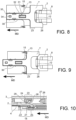
FIG. 8 is a schematic elevation view from above of the connector illustrated inFigures 1 and 2 , without its outer housing, and with the PLR in locking position; -
FIG. 9 is a schematic elevation view similar toFigure 8 , with the PLR in intermediate position; -
FIG. 10 is a schematic longitudinal and vertical cross-sectional view of a detail showing more particularly the primary and secondary locking means of the connector illustrated inFigures 1 and 2 ; -
FIG. 11 is a schematic perspective view of an example embodiment of a tool configured to actuate the PLR of the connector illustrated inFigures 1 and 2 ; -
FIG. 12 is a schematic partial cross-sectional view similar toFigures 4 and 5 , showing the PLR in locking position; -
FIG. 13 is a schematic partial cross-sectional view similar toFigure 12 , showing the PLR in intermediate position; -
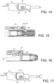
FIG. 14 is a schematic lateral elevation view of the connector illustrated inFigures 1 and 2 , without its outer housing, and showing the PLR in intermediate position; -
FIG. 15 is a schematic partial, longitudinal and vertical cross-sectional view of the connector illustrated inFigures 1 and 2 , without its outer housing, showing the PLR in unlocking position; -
FIG. 16 is a schematic cross-sectional view similar toFigure 15 , showing the PLR in intermediate position and a terminal partially removed from its cavity; and -
FIG. 17 is a lateral elevation view similar toFigure 14 , showing the PLR in unlocking position and a terminal completely removed from its cavity. - In this document, the terms "front", "rear", "above", "lateral", etc. and derivatives thereof refer to arbitrary orientations as shown on the drawings. However, it is to be understood that various alternative orientations may be used for illustrating this disclosure.
- In the drawings and in the description, same reference numbers are used for the same or similar elements.
-
Figure 1 shows an embodiment example of an electrical sealedconnector 1. This example ofconnector 1 is disclosed below. According to this example, theconnector 1 is a H-MTD® connector ("H-MTD" stands for High-Speed Modular Twisted-Pair Data). More particularly, according to this example, theconnector 1 is a two-ways cable connector. In this example, it is a male connector. Theconnector 1 is configured and intended to be connected in a mating direction MD to a counter-connector (in this example, a female connector which is not shown). -
Figure 2 is an exploded view of the connector illustrated inFigure 1 . Thiselectrical connector 1 comprises aninner housing 2, anouter housing 3, a pair ofmale terminals 4, a pair of single-wire seals 5, aretainer 6 and aPLR 7. Themale terminals 4 of H-MTD® connectors are particularly long. It is therefore difficult to use conventional PLR designs. Further, conventional PLRs are not much automation friendly. The PLR 7 disclosed here-below mitigates these drawbacks. - The
inner housing 2, theouter housing 3, theretainer 6 and thePLR 7 are made of molded plastics. Eachterminal 4 is crimped at the free end of a respectiveelectrical cable 8. Eachterminal 4 is made of an electrically conductive material. - The
inner housing 2 comprises twocavities 9 extending parallel to a longitudinal direction LD. In the illustrated example, theconnector 1 is a straight connector and this longitudinal direction LD is parallel to a mating direction MD (SeeFigures 6 and 7 ). The mating direction MD is the direction in which theconnector 1 is mated and connected to a counter-connector. Eachterminal 4 is respectively accommodated in one of the twocavities 9. Theinner housing 2 comprises anexternal surface 10 within which achannel 11 is formed (SeeFigures 2 and3 ). Theinner housing 2 further comprises afirst stop 12, asecond stop 13, primary locking means 14, spring means 15, the functions of which are disclosed below (SeeFigures 2 and3 ). - The
outer housing 3 comprises a mating face 16 (SeeFigures 1 ,4 to 7 ,12 and 13 ). Theouter housing 3 accommodates theinner housing 2. For example, theinner housing 2 is completely inserted in the outer housing 3 (SeeFigure 5 ). For example, theinner housing 2 is inserted in theouter housing 3 from its mating face 16 (i.e. its front face). When theinner housing 2 is fully (completely) inserted in theouter housing 3, afront sealing portion 17, open on themating face 16 of theouter housing 3, is cleared from theinner housing 2. In other words, thefront sealing portion 17 is configured to form a sealing barrier with a counter-connector mated to theconnector 1. Theouter housing 3 has arear sealing portion 18 configured to accommodate the single-wire seals 5. Therear sealing portion 18 is configured to form a sealing barrier with eachcable 8. Therefore, when theinner housing 2 is accommodated in theouter housing 3, when theconnector 1 is mated to a counter-connector and when thecables 8 and theseals 5 are mounted in theconnector 1, theconnector 1 is sealed (in particular against water and dust). - The
outer housing 3 has aresilient locking lance 19 configured to lock theinner housing 2 in theouter housing 3, when theinner housing 2 is fully inserted in the outer housing 3 (SeeFigure 5 ). - The
PLR 7 is mounted on theinner housing 2. ThePLR 7 is movable, between theinner housing 2 andouter housing 3, parallel to the longitudinal direction LD. In particular, when moving thePLR 7 parallel to the longitudinal direction LD, three positions can be identified along the corresponding path of PLR 7: a locking position (SeeFigures 3 ,8 ,10 and12 ), an unlocking position (SeeFigures 15 and 17 ) and an intermediate position (SeeFigures 4 to 7 ,9 ,13 ,14 and 16 ). The locking position and unlocking position correspond to the two ends of this path. The intermediate position is between the locking position and unlocking position. When thePLR 7 is pushed in a direction from thefront sealing portion 17 towards the rear sealing portion 18 (i.e. backwards), it is blocked by thefirst stop 12, in the locking position (SeeFigure 8 ). When thePLR 7 is pushed in a direction from therear sealing portion 18 towards the front sealing portion 17 (i.e. frontwards), it presses the spring means 15, until it abuts against thesecond stop 13, in the unlocking position (SeeFigure 17 ). ThePLR 7 is placed in the intermediate position for inserting theterminals 4 in their respective cavities 9 (SeeFigures 6 and 7 ). - In the locking position, the
front sealing portion 17 is cleared from theinner housing 2 and from thePLR 7, so that theconnector 1 can be mated to the counter-connector. In the locking position, theinner housing 2 and thePLR 7 are both located behind thefront sealing portion 17, with respect to the direction from thefront sealing portion 17 to the rear sealing portion 18 (SeeFigure 12 ). On the contrary, in the unlocking position and in the intermediate position, thePLR 7 partially protrudes in thefront sealing portion 17 and thereby prevents theconnector 1 from being connected to the counter-connector (SeeFigure 13 for example). - The primary locking means 14 comprises two
latches 20, twolugs 21 and two flexible branches 22 (SeeFigure 10 ). For example, eachflexible branch 22 extends backwards from theinner housing 2 towards onelatch 20 and onelug 21. For example, eachflexible branch 22 is located on one side of a cavity 9 (SeeFigures 6 and 7 ). Eachlatch 20 extends inwardly relatively to thecorresponding cavity 9, protrudes inside thiscavity 9 and is configured so as to lock oneterminal 4 accommodated in thiscavity 9. More particularly, alatch 20 locks aterminal 4, only when thisterminal 4 is fully inserted in itscavity 9 in a final and functional position. If aterminal 4 is not properly inserted in itscavity 9, thelatch 20 rests on thecorresponding terminal 4. - Each
lug 21 extends from aflexible branch 22, outwardly relatively to thecorresponding cavity 9. Eachlug 21 extends and protrudes in the pathway of thePLR 7. Therefore, when thelatch 20 rests on thecorresponding terminal 4, the correspondinglug 21 prevents thePLR 7 from being moved to the locking position. But, when alatch 20 locks aterminal 4, the correspondinglug 21 is retracted enough to allow thePLR 7 to move from the unlocking position, or intermediate position, to the locking position. In the intermediate position of thePLR 7, each terminal 4 in a final position is locked, in itsrespective cavity 4, by the primary locking means comprising thelatch 20. When thePLR 7 is in the locking position, it plays the role of a secondary locking means. Indeed, in the locking position, alocking section 23 of thePLR 7 covers thelatch 20 and thelug 21, and prevents theflexible branches 22 from lifting (SeeFigures 3 ,8 and 10 ). In other words, in the locking position, thePLR 7 blocks the outward movement of each lug 21 (SeeFigure 10 ). For example, the lockingsection 23 has two lockingwings 24, each one of which covering alatch 20 and alug 21. - The
PLR 7 also has an unlocking section comprising two unlockingwings 26. Each one of these two unlockingwings 26 bears one unlocking surfaces 27. - Each
lug 21 has a first slantedsurface 28 and a second slanted surface 29 (SeeFigure 10 ). The first slantedsurface 28 of eachlug 21 is configured to engage the unlockingsurface 27 of thePLR 7, when thePLR 7 is moved from the locking position to the unlocking position. In particular, when thePLR 7 is moved from the intermediate position and the unlocking position, each unlockingsurface 27 lifts thecorresponding branch 22, thereby releasing the corresponding terminal 4 from the correspondinglatch 20. In other words, in the unlocking position of thePLR 7, eachterminal 4 is released from the primary locking means. On the contrary, each second slantedsurface 29 is configured so as not to block the movement of thePLR 7 towards the locking position. In other words, if the PLR were to touch this second slantedsurface 29, the latter is oriented so that thePLR 7 slides over it. - The
PLR 7 has an actuating leg 30 (SeeFigures 8 and 9 ). When thePLR 7 is mounted in theconnector 1, theactuating leg 30 extends longitudinally from the lockingsection 23 toward the mating face 16 (i.e. in the mating direction MD). Thisactuating leg 30 is configured to be accessible from the mating face 16 (SeeFigure 12 ). Theactuating leg 30 comprises a first hookingportion 31 configured to actuate thePLR 7 from the intermediate position to the locking position and vice-versa. Indeed, theinner housing 2 has awindow 32 and the first hookingportion 31 has aslot 33. Atool 100 can be used to penetrate both thewindow 32 and theslot 33. Once thetool 100 engages theslot 33, an operator can pull thetool 100, thereby moving thePLR 7 from the locking position toward the unlocking position, to place thePLR 7 in the intermediate position. In the intermediate position, thetool 100 is blocked by an edge of the window 32 (SeeFigure 13 ). Then, thetool 100 is removed from theslot 33 and is possibly inserted in anotch 34 of a second hookingportion 35 of theactuating leg 30. Once thetool 100 engages thenotch 34, an operator can pull thetool 100, thereby moving thePLR 7 from the intermediate position toward the unlocking position, to place thePLR 7 in the unlocking position. From the intermediate position to the unlocking position, the lockingsection 23 presses the spring means 15 and the unlockingsurfaces 27 engage the firstslanted surfaces 28 to lift the branches 22 (SeeFigures 15 and 17 ). As a result to lift thelatches 20, theterminals 4 are released. When thetool 100 is removed from thenotch 34, the spring means 15 returns thePLR 7 to the intermediate position. - Indexing means 35 may be used to help an operator to position the PLR 7 (see
Figure 3 ). For example, the indexing means 35 comprise arib 36 on both lateral sides of theactuating leg 30 and twogrooves 37 in thechannel 11. Thegrooves 37 are positioned along the PLR path so as to index the locking position and the intermediate position. Eachrib 36 is born by aflexible bridge 38. - For assembling the
connector 1, at least the following steps are performed: - positioning the
PLR 7 onto theinner housing 2,- inserting in the
outer housing 3, theinner housing 2 with thePLR 7 positioned onto it, up to a locked position where theinner housing 2 is locked to the outer housing 3 (for example with the locking lance 19), - inserting each terminal 4 in a
respective cavity 9 of theinner housing 2, up to a final position, where it is locked in theinner housing 2 by primary locking means 14 formed on the inner housing 2 (i.e. the latches 20), - moving the
PLR 7 from an unlocking position or an intermediate position, where it does not block the primary locking means 14, to a locking position, where each lockingwing 24 prevents therespective lug 21 to lift, prevents therespective latch 20 to escape from thecorresponding cavity 9 and consequently prevents therespective terminal 4 from being removed from itscavity 9 if pulled back towards therear sealing portion 18.
- inserting in the
- For removing the
terminals 4 from theconnector 1, thePLR 7 is moved from the locking position to the unlocking position, with atool 100. Possibly thePLR 7 is moved from the locking position to the unlocking position in two steps: a) from the locking position to the intermediate position, with thetool 100 inserted in the first hooking section 23 (i.e. the slot 33) , and b) from the intermediate position to the unlocking position, with thetool 100 inserted in the second hooking section (i.e. the notch 34). Thereby, the unlockingsurfaces 27 lift thelugs 21 and release theterminals 4 from thelatches 20. - The
connector 1 and the assembling method have several advantages. For example, - the use of a
tool 100 inserted in the inner 2 and outer 3 housings allows for a reduced length of theconnector 1; - the
actuating leg 30 partially protruding in thefront sealing portion 17 prevents a counter-connector to be mated to theconnector 1 if theterminals 4 are not well positioned in theirrespective cavities 9; an incorrect insertion of theterminals 4 can be easily detected by an automation actuator due to the low drive load and the possibility to predict the resistive force; - the self-locking of the
PLR 7 thanks to thelocking lance 19 makes theconnector 1 automation friendly (no separate PLR actuator is required); - the
PLR 7 can easily be opened and closed without moving thehousing parts terminals 4.
Claims (11)
- Electrical connector (1) comprising- an inner housing (2) comprising at least two cavities (9) extending parallel to a longitudinal direction (LD),- an outer housing (3) comprising a mating face (16) and being configured to at least partially accommodate the inner housing (2),- at least two terminals (4), each one of which being accommodated in one of said at least two cavities (9),- a PLR (7),characterized in that the PLR (7) is mounted on the inner housing (2) and is configured to be moved, between the inner (2) and outer (3) housings, parallel to the longitudinal direction (LD), between at least three positions,- a locking position where the PLR (7) is completely covered by the outer housing (3), where a front sealing portion (17) open on the mating face (16) of the outer housing (3) is cleared from the inner housing (2) and the PLR (7), and where the PLR (7) provides a secondary locking means blocking primary locking means (14) that locks each one of said at least two terminals (4), in a final position in its respective cavity (9),- an intermediate position in which each one of said at least two terminals (4) is locked by the primary locking means (14) in the final position in its respective cavity (9), and- an unlocking position where each one of said at least two terminals (4) is released from the primary locking means (14).
- Electrical connector (1) according to claim 1, wherein the inner housing (2) has at least two latches (20), each one of these two latches (20) being configured to form the primary locking means (14).
- Electrical connector (1) according to claim 2, wherein the PLR (7) comprises at least two unlocking surfaces (27), each one of these two unlocking surfaces (27) being configured to lift one of said at least two latches (20), when the PLR (7) is moved from its locking position and to its unlocking position.
- Electrical connector (1) according to claim 3, wherein the PLR (7) has an unlocking section (25) comprising at least two unlocking wings (26), each one of these two unlocking wings (26) bearing one of said at least two unlocking surfaces (27).
- Electrical connector (1) according to claim 3 or 4, wherein the PLR (7) has an actuating leg extending longitudinally from the locking section toward the mating face (16), this actuating leg (30) being configured to be accessible from the mating face (16).
- Electrical connector (1) according to any of the preceding claims, wherein the outer housing (3) comprises the front sealing portion (17) and a rear sealing portion (18), the outer housing (3) being completely closed between the front sealing portion (17) and the rear sealing portion (18), the inner housing (2) and the PLR (7) being both located behind the front sealing portion (17), with respect to the direction from the front sealing portion (17) to the rear sealing portion (18), when the PLR (7) is in its locking position.
- A connector (1) according to any one of the preceding claims, wherein the PLR (7) comprises a first hooking portion (31) configured for actuating the PLR (7) from the intermediate position to the locking position and vice-versa.
- A connector (1) according to any one of the preceding claims, wherein the PLR (7) comprises a second hooking portion configured for actuating the PLR (7) from an intermediate position to its unlocking position and vice-versa.
- A method of assembling an electrical connector (1), comprising the step of providing an inner housing (2), an outer housing (3), at least two terminals (4), and a PLR (7), characterized in that the method further comprises the steps of- positioning the PLR (7) onto the inner housing (2),- inserting in the outer housing (3), the inner housing (2) with the PLR (7) positioned onto it, up to a locked position where the inner housing (2) is locked to the outer housing (3),- inserting each terminal (4) in the inner housing (2), up to a final position, where it is locked in the inner housing (2) by primary locking means (14) formed on the inner housing (2),- moving the PLR (7) from a position, where it does not block the primary locking means (14), to a locking position, where it blocks the primary locking means (14) and where a front sealing portion (17) open on a mating side (16) of the outer housing (3) is cleared from the inner housing (2) and the PLR (7).
- A method of assembling an electrical connector (1) according to claim 9, wherein the step of moving the PLR (7) from the unlocking position to the locking position, is performed with a tool (100) engaging the PLR (7).
- A method of removing a terminal (4) from a connector (1) according to any one of claims 1 to 8, comprising hooking the PLR (7) with a tool (100) and pulling the tool (100) so as to move the PLR (7) from its locking position and its unlocking position, thereby releasing each terminal (4).
Priority Applications (2)
| Application Number | Priority Date | Filing Date | Title |
|---|---|---|---|
| EP23174976.3A EP4468526A1 (en) | 2023-05-23 | 2023-05-23 | Sealed connector with a plr having terminal unlocking means |
| US18/672,451 US20240396249A1 (en) | 2023-05-23 | 2024-05-23 | Sealed connector with a primary lock reinforcement device having terminal unlocking means |
Applications Claiming Priority (1)
| Application Number | Priority Date | Filing Date | Title |
|---|---|---|---|
| EP23174976.3A EP4468526A1 (en) | 2023-05-23 | 2023-05-23 | Sealed connector with a plr having terminal unlocking means |
Publications (1)
| Publication Number | Publication Date |
|---|---|
| EP4468526A1 true EP4468526A1 (en) | 2024-11-27 |
Family
ID=86497582
Family Applications (1)
| Application Number | Title | Priority Date | Filing Date |
|---|---|---|---|
| EP23174976.3A Pending EP4468526A1 (en) | 2023-05-23 | 2023-05-23 | Sealed connector with a plr having terminal unlocking means |
Country Status (2)
| Country | Link |
|---|---|
| US (1) | US20240396249A1 (en) |
| EP (1) | EP4468526A1 (en) |
Citations (2)
| Publication number | Priority date | Publication date | Assignee | Title |
|---|---|---|---|---|
| EP3713018A1 (en) * | 2019-03-20 | 2020-09-23 | Rosenberger Hochfrequenztechnik GmbH & Co. KG | Electric connector, secondary fuse and method for mounting of an electric connector |
| US10826220B1 (en) * | 2019-09-25 | 2020-11-03 | Lear Corporation | Electrical connector having electrical terminal servicing feature |
-
2023
- 2023-05-23 EP EP23174976.3A patent/EP4468526A1/en active Pending
-
2024
- 2024-05-23 US US18/672,451 patent/US20240396249A1/en active Pending
Patent Citations (2)
| Publication number | Priority date | Publication date | Assignee | Title |
|---|---|---|---|---|
| EP3713018A1 (en) * | 2019-03-20 | 2020-09-23 | Rosenberger Hochfrequenztechnik GmbH & Co. KG | Electric connector, secondary fuse and method for mounting of an electric connector |
| US10826220B1 (en) * | 2019-09-25 | 2020-11-03 | Lear Corporation | Electrical connector having electrical terminal servicing feature |
Also Published As
| Publication number | Publication date |
|---|---|
| US20240396249A1 (en) | 2024-11-28 |
Similar Documents
| Publication | Publication Date | Title |
|---|---|---|
| US11342708B2 (en) | Set of connectors having a locking device | |
| US7438570B2 (en) | Lever fitting-type connector | |
| KR200465368Y1 (en) | Electrical connector assembly having connector position assurance device | |
| CN107465030B (en) | The method of electric connector assembling part and assembling electric connector assembling part | |
| US6244880B1 (en) | Low-insertion force connector | |
| EP3591769B1 (en) | Connector device | |
| US6241542B1 (en) | Connector with shorting terminal | |
| EP3392979B1 (en) | Electrical connector with lever and methods of assembling thereof | |
| US7867042B2 (en) | Connector assembly with a low profile terminal position assurance member | |
| EP1571734B1 (en) | Connector apparatus with a mating detecting member called connector position assurance | |
| JP2002305052A (en) | Connector | |
| WO2009120283A2 (en) | Connector assembly having primary and secondary locking features | |
| US6109965A (en) | Connector provided with a retainer | |
| EP0976175B1 (en) | Connector with secondary locking and coupling mechanism | |
| EP1162704B1 (en) | A connector and a method for detaching housings thereof | |
| US11888254B2 (en) | Connector assembly comprising module with integrated terminal position assurance means | |
| CN1332479C (en) | A breakaway connector and a method of disengaging an auxiliary connector housing therefrom | |
| CN101218716B (en) | electrical connector | |
| US20250219321A1 (en) | High voltage electrical connector | |
| US20240396249A1 (en) | Sealed connector with a primary lock reinforcement device having terminal unlocking means | |
| EP4468525A1 (en) | Sealed connector with self locking tpa | |
| EP4054018A1 (en) | Electrical connector system with miniaturized connector position assurance member | |
| JP3125850B2 (en) | Connector with terminal locking member, molding apparatus and manufacturing method thereof | |
| EP4485708A1 (en) | Electrical power connector with locking cpa and method for using it in a connection | |
| EP1085612A1 (en) | A connector |
Legal Events
| Date | Code | Title | Description |
|---|---|---|---|
| PUAI | Public reference made under article 153(3) epc to a published international application that has entered the european phase |
Free format text: ORIGINAL CODE: 0009012 |
|
| STAA | Information on the status of an ep patent application or granted ep patent |
Free format text: STATUS: THE APPLICATION HAS BEEN PUBLISHED |
|
| AK | Designated contracting states |
Kind code of ref document: A1 Designated state(s): AL AT BE BG CH CY CZ DE DK EE ES FI FR GB GR HR HU IE IS IT LI LT LU LV MC ME MK MT NL NO PL PT RO RS SE SI SK SM TR |
|
| STAA | Information on the status of an ep patent application or granted ep patent |
Free format text: STATUS: REQUEST FOR EXAMINATION WAS MADE |
|
| 17P | Request for examination filed |
Effective date: 20250526 |