EP4468037A1 - Detection method, detection program, and work vehicle - Google Patents
Detection method, detection program, and work vehicle Download PDFInfo
- Publication number
- EP4468037A1 EP4468037A1 EP24175729.3A EP24175729A EP4468037A1 EP 4468037 A1 EP4468037 A1 EP 4468037A1 EP 24175729 A EP24175729 A EP 24175729A EP 4468037 A1 EP4468037 A1 EP 4468037A1
- Authority
- EP
- European Patent Office
- Prior art keywords
- detection
- work
- route
- unit
- target
- Prior art date
- Legal status (The legal status is an assumption and is not a legal conclusion. Google has not performed a legal analysis and makes no representation as to the accuracy of the status listed.)
- Pending
Links
Images







Classifications
-
- G—PHYSICS
- G05—CONTROLLING; REGULATING
- G05D—SYSTEMS FOR CONTROLLING OR REGULATING NON-ELECTRIC VARIABLES
- G05D1/00—Control of position, course, altitude or attitude of land, water, air or space vehicles, e.g. using automatic pilots
- G05D1/60—Intended control result
- G05D1/648—Performing a task within a working area or space, e.g. cleaning
- G05D1/6484—Performing a task within a working area or space, e.g. cleaning by taking into account parameters or characteristics of the working area or space, e.g. size or shape
- G05D1/6486—Performing a task within a working area or space, e.g. cleaning by taking into account parameters or characteristics of the working area or space, e.g. size or shape by taking into account surface condition, e.g. soiled
-
- A—HUMAN NECESSITIES
- A01—AGRICULTURE; FORESTRY; ANIMAL HUSBANDRY; HUNTING; TRAPPING; FISHING
- A01D—HARVESTING; MOWING
- A01D41/00—Combines, i.e. harvesters or mowers combined with threshing devices
- A01D41/12—Details of combines
- A01D41/127—Control or measuring arrangements specially adapted for combines
- A01D41/1278—Control or measuring arrangements specially adapted for combines for automatic steering
-
- G—PHYSICS
- G05—CONTROLLING; REGULATING
- G05D—SYSTEMS FOR CONTROLLING OR REGULATING NON-ELECTRIC VARIABLES
- G05D1/00—Control of position, course, altitude or attitude of land, water, air or space vehicles, e.g. using automatic pilots
- G05D1/60—Intended control result
- G05D1/644—Optimisation of travel parameters, e.g. of energy consumption, journey time or distance
-
- A—HUMAN NECESSITIES
- A01—AGRICULTURE; FORESTRY; ANIMAL HUSBANDRY; HUNTING; TRAPPING; FISHING
- A01B—SOIL WORKING IN AGRICULTURE OR FORESTRY; PARTS, DETAILS, OR ACCESSORIES OF AGRICULTURAL MACHINES OR IMPLEMENTS, IN GENERAL
- A01B69/00—Steering of agricultural machines or implements; Guiding agricultural machines or implements on a desired track
-
- A—HUMAN NECESSITIES
- A01—AGRICULTURE; FORESTRY; ANIMAL HUSBANDRY; HUNTING; TRAPPING; FISHING
- A01D—HARVESTING; MOWING
- A01D41/00—Combines, i.e. harvesters or mowers combined with threshing devices
- A01D41/02—Self-propelled combines
-
- G—PHYSICS
- G01—MEASURING; TESTING
- G01S—RADIO DIRECTION-FINDING; RADIO NAVIGATION; DETERMINING DISTANCE OR VELOCITY BY USE OF RADIO WAVES; LOCATING OR PRESENCE-DETECTING BY USE OF THE REFLECTION OR RERADIATION OF RADIO WAVES; ANALOGOUS ARRANGEMENTS USING OTHER WAVES
- G01S17/00—Systems using the reflection or reradiation of electromagnetic waves other than radio waves, e.g. lidar systems
- G01S17/88—Lidar systems specially adapted for specific applications
- G01S17/93—Lidar systems specially adapted for specific applications for anti-collision purposes
- G01S17/931—Lidar systems specially adapted for specific applications for anti-collision purposes of land vehicles
-
- G—PHYSICS
- G05—CONTROLLING; REGULATING
- G05D—SYSTEMS FOR CONTROLLING OR REGULATING NON-ELECTRIC VARIABLES
- G05D1/00—Control of position, course, altitude or attitude of land, water, air or space vehicles, e.g. using automatic pilots
- G05D1/20—Control system inputs
- G05D1/24—Arrangements for determining position or orientation
- G05D1/242—Means based on the reflection of waves generated by the vehicle
- G05D1/2424—Means based on the reflection of waves generated by the vehicle for monitoring a plurality of zones
-
- G—PHYSICS
- G05—CONTROLLING; REGULATING
- G05D—SYSTEMS FOR CONTROLLING OR REGULATING NON-ELECTRIC VARIABLES
- G05D1/00—Control of position, course, altitude or attitude of land, water, air or space vehicles, e.g. using automatic pilots
- G05D1/20—Control system inputs
- G05D1/24—Arrangements for determining position or orientation
- G05D1/242—Means based on the reflection of waves generated by the vehicle
- G05D1/2427—Means based on the reflection of waves generated by the vehicle for monitoring a zone of adjustable size or form
-
- G—PHYSICS
- G05—CONTROLLING; REGULATING
- G05D—SYSTEMS FOR CONTROLLING OR REGULATING NON-ELECTRIC VARIABLES
- G05D1/00—Control of position, course, altitude or attitude of land, water, air or space vehicles, e.g. using automatic pilots
- G05D1/40—Control within particular dimensions
- G05D1/43—Control of position or course in two dimensions [2D]
-
- G—PHYSICS
- G05—CONTROLLING; REGULATING
- G05D—SYSTEMS FOR CONTROLLING OR REGULATING NON-ELECTRIC VARIABLES
- G05D1/00—Control of position, course, altitude or attitude of land, water, air or space vehicles, e.g. using automatic pilots
- G05D1/60—Intended control result
- G05D1/617—Safety or protection, e.g. defining protection zones around obstacles or avoiding hazards
-
- G—PHYSICS
- G05—CONTROLLING; REGULATING
- G05D—SYSTEMS FOR CONTROLLING OR REGULATING NON-ELECTRIC VARIABLES
- G05D1/00—Control of position, course, altitude or attitude of land, water, air or space vehicles, e.g. using automatic pilots
- G05D1/60—Intended control result
- G05D1/648—Performing a task within a working area or space, e.g. cleaning
-
- G—PHYSICS
- G05—CONTROLLING; REGULATING
- G05D—SYSTEMS FOR CONTROLLING OR REGULATING NON-ELECTRIC VARIABLES
- G05D1/00—Control of position, course, altitude or attitude of land, water, air or space vehicles, e.g. using automatic pilots
- G05D1/60—Intended control result
- G05D1/648—Performing a task within a working area or space, e.g. cleaning
- G05D1/6484—Performing a task within a working area or space, e.g. cleaning by taking into account parameters or characteristics of the working area or space, e.g. size or shape
-
- G—PHYSICS
- G05—CONTROLLING; REGULATING
- G05D—SYSTEMS FOR CONTROLLING OR REGULATING NON-ELECTRIC VARIABLES
- G05D2105/00—Specific applications of the controlled vehicles
- G05D2105/15—Specific applications of the controlled vehicles for harvesting, sowing or mowing in agriculture or forestry
-
- G—PHYSICS
- G05—CONTROLLING; REGULATING
- G05D—SYSTEMS FOR CONTROLLING OR REGULATING NON-ELECTRIC VARIABLES
- G05D2107/00—Specific environments of the controlled vehicles
- G05D2107/20—Land use
- G05D2107/21—Farming, e.g. fields, pastures or barns
-
- G—PHYSICS
- G05—CONTROLLING; REGULATING
- G05D—SYSTEMS FOR CONTROLLING OR REGULATING NON-ELECTRIC VARIABLES
- G05D2109/00—Types of controlled vehicles
- G05D2109/10—Land vehicles
Definitions
- the present invention relates to a detection method, a detection program, and a work vehicle for detecting a detection target around an automatically traveling work vehicle.
- a known work vehicle for example, a combine harvester automatically travels in a field in accordance with a target route set in advance (for example, see Patent Document 1).
- a combine harvester includes a reaping unit that reaps grain culms and a detection unit that detects an obstacle, and performs a reaping work by the reaping unit while determining the presence or absence of an obstacle ahead in the traveling direction.
- Patent Document 1 Japanese Unexamined Patent Application Publication No. 2021-185852
- a conventional work vehicle When traveling in the work area, a conventional work vehicle performs, for example, a process of excluding a predetermined range from the detection target so that a work object (for example, grain culms) is not recognized as the obstacle.
- a work object for example, grain culms
- applying this process causes an inconvenience in that the detection target (persons, objects, or the like) within the predetermined range cannot appropriately be detected as the obstacle when the work vehicle travels in a non-work area or a work-completed area.
- An object of the present invention is to provide a detection method, a detection program, and a work vehicle capable of appropriately detecting a detection target as an obstacle.
- a detection method detects a detection target around a work vehicle by a detection unit provided in the work vehicle that automatically travels along a target route, and sets a detection function for the detection target to be enabled or disabled based on the target route.
- a detection program is a detection program for detecting a detection target around a work vehicle by a detection unit provided in the work vehicle that automatically travels along a target route, the detection program causing one or more processors to execute setting of a detection function for the detection target to be enabled or disabled based on the target route.
- a work vehicle includes a detection unit capable of detecting a surrounding detection target, travels automatically along a target route, and includes a setting processing unit that sets a detection function for the detection target to be enabled or disabled based on the target route, and a detection processing unit that causes the work vehicle to execute predetermined processing for the detection target in accordance with a setting state of the detection function.
- a detection method, a detection program, and a work vehicle capable of appropriately detecting a detection target as an obstacle.
- a combine harvester 1 is described as an example of the work vehicle of the present invention.
- a traveling system 10 includes a combine harvester 1 and an operation terminal 30.
- the combine harvester 1 and the operation terminal 30 can communicate with each other via a communication network N1.
- the combine harvester 1 and the operation terminal 30 can communicate via a mobile phone network, a packet network, or a wireless local area network (LAN).
- LAN wireless local area network
- the combine harvester 1 is a work vehicle that performs agricultural work (an example of a predetermined work of the present invention) such as reaping in a field.
- the combine harvester 1 works while traveling, and transmits global navigation satellite system (GNSS) information of a GNSS antenna mounted on the combine harvester 1, that is, the own position of the combine harvester 1 as measurement point data to the operation terminal 30.
- GNSS global navigation satellite system
- the combine harvester 1 can automatically travel along a preset target route.
- the combine harvester 1 may be configured to automatically travel in a partial area of the field (for example, a straight route) and to manually travel in other areas of the field (for example, a turning route).
- the combine harvester 1 receives various kinds of setting information from the operation terminal 30, and automatically travels in accordance with the setting information.
- the operation terminal 30 is a portable terminal capable of remotely operating the combine harvester 1, and is composed of, for example, a tablet terminal, a notebook personal computer, a smart phone, or the like. An operation device similar to the operation terminal 30 may be provided in the combine harvester 1.
- a worker can perform the setting operation for various setting items on the operation terminal 30.
- the operation terminal 30 also displays the information such as a work state, a traveling state, or the like of the combine harvester 1 during autonomous traveling. The operator can recognize the work state and traveling state at the operation terminal 30.
- the operation terminal 30 may be omitted in the present invention.
- Fig. 4 illustrates an example of a target route R set for a field F.
- the combine harvester 1 performs a reaping work ("round reaping", "reciprocating reaping") in the field F from a start position S to an end position G along the target route R while traveling from the outer peripheral side to the inner peripheral side.
- a reaping work (“round reaping", "reciprocating reaping"
- the combine harvester 1 performs the reaping work while traveling along the edge (outer periphery) of the field.
- an inner peripheral area F2 on the inner peripheral side of the field F the combine harvester 1 performs the reaping work while traveling straight on each work route in the vertical direction of Fig. 4 , while moving between the work routes by turning and straight traveling without doing the reaping work in the left-right direction.
- the combine harvester 1 starts the automatic travel from the start position S and travels along the outer periphery of the field F while reaping grain culms.
- the combine harvester 1 threshes the reaped grain culms and externally discharges waste straws such as straw debris from the rear of the machine body to the outside. Accordingly, the waste straws B1 are accumulated in the traveling track of the combine harvester 1, and a waste straw row is formed on the route where the combine harvester 1 has finished the reaping work.
- the combine harvester 1 is set to discharge the waste straws of the reaped grain culms at the positions of the grain culms to be reaped, and is configured to grasp positions, a width (a lateral width in the left-right direction of the waste straw row), a length, and the like of the waste straws B 1.
- the waste straws B1 are discharged in a width narrower than the lateral width of the machine body with reference to the center in the left-right direction of the combine harvester 1.
- the combine harvester 1 goes around the outer peripheral area F1 twice. In this case, a waste straw row for two rounds is formed.
- the number of turns of the outer peripheral area F1 is not limited to two, and may be one or three or more.
- the combine harvester 1 After finishing the reaping work of the outer peripheral area F1, the combine harvester 1 enters the inner peripheral area F2 and starts the reaping work of the inner peripheral area F2.
- the combine harvester 1 performs the reaping work in the vertical direction of Fig. 5 while traveling straight on each work route, and moves between the work routes by turning and traveling straight in the outer peripheral area F1 (a work-completed area, a reaped area) without performing the reaping work in the left-right direction.
- the combine harvester 1 performs the reaping work in the inner peripheral area F2, and finishes the automatic traveling and the reaping work when reaching the end position G.
- the combine harvester 1 performs the reaping operation while automatically traveling along the target route R in the field F as described above.
- the combine harvester 1 may be configured to automatically travel without the operator on board, may be configured to automatically travel with the operator on board while receiving an operation from the operator, or may be configured to travel in response to manual steering by the operator (manual travel).
- the combine harvester 1 may also be switchable between the automatic travel mode and the manual travel mode in accordance with a setting operation by the operator.
- the operation terminal 30 is an information processing device including an operation control unit 31, a storage unit 32, an operation display unit 33, a communication unit 34, and the like.
- the operation terminal 30 is composed of, for example, a tablet terminal.
- the storage unit 32 includes a dedicated application installed for enabling the automatic travel of the combine harvester 1.
- the operation control unit 31 activates the dedicated application to execute setting processing of various types setting information about the combine harvester 1, issue an automatic travel instruction to the combine harvester 1, and the like.
- Fig. 2 is an external view of the combine harvester 1 when viewed from the side
- Fig. 3 is an external view of the combine harvester 1 when viewed from above.
- the combine harvester 1 includes a traveling unit 2, a reaping unit 3, a threshing unit 4, a sorting unit 5, a reservoir unit 6, a waste straw processing unit 7, a power unit 8, a steering unit 9, a control device 11, a storage unit 51, a positioning unit 52, a detection unit 53, a communication unit 54, and the like.
- the combine harvester 1 While traveling by the traveling unit 2, the combine harvester 1 reaps grain culms by the reaping unit 3, threshes the reaped grain culms by the threshing unit 4, sorts grains by the sorting unit 5, and accumulates the grains in the reservoir unit 6.
- the combine harvester 1 also processes the waste straws after threshing by the waste straw processing unit 7.
- the combine harvester 1 uses the power supplied from the power unit 8 to drive the traveling unit 2, the reaping unit 3, the threshing unit 4, the sorting unit 5, the reservoir unit 6, and the waste straw processing unit 7.
- the traveling unit 2 is provided under a machine body frame 12, and includes a pair of left and right crawler-type traveling device 23 and a transmission (not illustrated).
- the traveling unit 2 uses the power (for example, the rotational power) transmitted from the engine 20 of the power unit 8 to rotate the crawlers of the crawler-type traveling device 23, thus traveling the combine harvester 1 in the front-rear direction or turn in the left-right direction.
- the transmission transmits the power (rotational power) of the power unit 8 to the crawler-type traveling device 23 and can also change the speed of the rotational power.
- the reaping unit 3 is a work machine that performs work on the field F to be worked and is provided in front of the traveling unit 2, reaping the grain culms over a predetermined reaping width in an area in which nonreaped grain culms are present, which is an unworked area of the field F (hereinafter referred to as an unreaped area).
- the reaping unit 3 is an example of a work unit of the present invention.
- the reaping unit 3 includes a divider 13, a raking reel 14, a reaping blade 15, a raking auger 16, a feeder house 17, and a transport conveyor 18.
- the reaping unit 3 includes a rotation detection unit (not illustrated) that detects a rotation speed (work speed) of a rotation work for performing the reaping work.
- the rotation detection unit is composed of, for example, a rotation sensor that detects the rotation speed of the raking reel 14, the rotation speed of the raking auger 16, and the rotation speed of the transport conveyor 18.
- the divider 13 is provided to protrude forward from the left front end and the right front end of the reaping unit 3, and guides the grain culms in the unreaped area to put them within the reaping width.
- the raking reel 14 is located behind the divider 13 to be rotatable around a rotation axis extending in the left-right direction. In order to assist reaping of the grain culms guided by the divider 13, the raking reel 14 is rotationally driven to rake the ear tip side of the grain culms while raising the grain culms.
- the reaping blade 15 is disposed under the raking reel 14 and reaps the grain culms by cutting the culm base side of the grain culms having been raked by the raking reel 14.
- the raking auger 16 is disposed behind the raking reel 14 and the reaping blade 15 and is provided rotatably around a rotation axis extending in the left-right direction.
- the raking auger 16 is rotationally driven to rake the grain culms having been reaped by the reaping blade 15 and transports the grain culms rearward.
- the feeder house 17 extends forward from the machine body frame 12 to be located behind the raking auger 16, and is supported by the machine body frame 12 in a manner capable of lifting and lowering. Lifting and lowering the feeder house 17 causes lifting and lowering of the divider 13, the raking reel 14, the reaping blade 15, and the raking auger 16, that is, the reaping unit 3.
- the combine harvester 1 includes, in the machine body frame 12, a lifting and lowering device 19 that causes lifting and lowering of the feeder house 17 to lift and lower the reaping unit 3, thus lifting and lowering the reaping unit 3 between a working position (see Fig. 2 ) and a non-working position (not illustrated).
- the lifting and lowering device 19 is composed of a hydraulic cylinder or the like that operates upon receipt of power from the engine 20.
- the transport conveyor 18 is provided in a rotatable manner in the feeder house 17 and moves along with the lifting and lowering of the feeder house 17.
- the transport conveyor 18 is rotationally driven to transport the grain culms conveyed into the feeder house 17 by the raking auger 16 further rearward to the threshing unit 4.
- the threshing unit 4 is provided behind the feeder house 17 of the reaping unit 3, and threshes the grain culms transported from the feeder house 17.
- the threshing unit 4 includes a threshing cylinder 21 and a receiving net 22.
- the threshing cylinder 21 threshes grains from grain culms transported from the feeder house 17, and transports the threshed grain culms, that is, waste straws to the waste straw processing unit 7.
- the receiving net 22 supports the grain culms transported by the threshing cylinder 21, and sieves the grains to let them fall.
- the sorting unit 5 is provided under the threshing unit 4.
- the sorting unit 5 includes a swing sorting device 24, a blower sorting device 25, a grain transport device (not illustrated), and a straw debris discharging device (not illustrated).
- the swing sorting device 24 sieves the threshed grains fallen from the threshing unit 4 and sorts them into grains, straw debris, and the like.
- the blower sorting device 25 further sorts the threshed grains fallen from the threshing unit 4 or the threshed grains sorted by the swing sorting device 24 into grains, straw debris, and the like by blowing air.
- the grain transport device transports the grains sorted by the swing sorting device 24 and the blower sorting device 25 to the reservoir unit 6.
- the waste straw discharging device discharges the straw debris and the like other than the grains sorted by the swing sorting device 24 and the blower sorting device 25 to the outside of the machine.
- the reservoir unit 6 is provided on the right side of the threshing unit 4.
- the reservoir unit 6 includes a reservoir tank (grain tank) 27 and a grain discharging device 28.
- the reservoir tank 27 accumulates the grains transported from the sorting unit 5.
- the grain discharging device 28 includes a discharging auger or the like to perform a discharging work of the grains to discharge the grains accumulated in the reservoir tank 27 to the transport vehicle at a predetermined discharge position.
- the waste straw processing unit 7 is provided behind the threshing unit 4.
- the waste straw processing unit 7 includes a waste straw transport device (not illustrated) and a waste straw cutting device (not illustrated).
- the waste straw processing unit 7 uses the waste straw transport device to transport the waste straws transported from the threshing unit 4 to the waste straw cutting device, and, after cutting the waste straws by the waste straw cutting device, discharges the cut waste straws to the rear of the combine harvester 1 (see Fig. 5 ).
- the power unit 8 is provided above the traveling unit 2 and below the reservoir unit 6.
- the power unit 8 includes the engine 20 which generates rotational power.
- the power unit 8 transmits the rotational power generated by the engine 20 to the traveling unit 2, the reaping unit 3, the threshing unit 4, the sorting unit 5, the reservoir unit 6, and the waste straw processing unit 7.
- the combine harvester 1 also includes a fuel tank that stores a fuel to be supplied to the engine 20 of the power unit 8.
- the steering unit 9 is provided above the power unit 8.
- the steering unit 9 includes operation devices to steer the travel of the combine harvester 1 around the driver's seat which is a seat 40 on which the operator sits, such as a steering wheel to provide a turn instruction of the machine body of the combine harvester 1, and main and auxiliary speed levers to provide a speed change instruction of the forward and rearward travel of the combine harvester 1.
- Manual traveling of the combine harvester 1 is executed by the traveling unit 2 when it accepts operations of the steering wheel and the main and auxiliary speed change levers of the steering unit 9.
- the steering unit 9 also includes a mechanism for operating the reaping work by the reaping unit 3, the threshing work by the threshing unit 4, the discharging work by the grain discharging device 28 from the reservoir unit 6, and the like.
- the positioning unit 52 acquires the own position of the combine harvester 1 using a satellite positioning system such as a global positioning system (GPS) or the like.
- a satellite positioning system such as a global positioning system (GPS) or the like.
- the positioning unit 52 receives a positioning signal from a positioning satellite via a positioning antenna, and acquires position information of the positioning unit 52, that is, the own position of the combine harvester 1 (measurement point data), based on the positioning signal.
- the positioning unit 52 may be composed of a quantum compass instead of the positioning antenna.
- the communication unit 54 is a communication interface for connecting the combine harvester 1 to the communication network N1 by wire or wirelessly and performing data transmission with external devices such as the operation terminal 30 via the communication network N1 in accordance with a predetermined communication protocol.
- the storage unit 51 is a non-volatile storage unit such as an HDD, an SSD, or a flash memory that stores various kinds of information.
- the storage unit 51 stores a control program such as a travel program for causing the control device 11 to execute traveling processing (see Fig. 13 ) which will be described later.
- the travel program is non-transitorily recorded in a computer-readable recording medium such as a flash ROM, an EEPROM, a CD, or a DVD, read by a predetermined reading device (not illustrated), and stored in the storage unit 51.
- the travel program may be downloaded from a server (not illustrated) to the combine harvester 1 via the communication network N1 and stored in the storage unit 51.
- the storage unit 51 also stores various types of setting information acquired from the operation terminal 30.
- the detection unit 53 is a sensor that detects a detection target in a predetermined detection range using infrared rays, ultrasonic waves, and the like.
- the detection unit 53 may be a lidar sensor (distance sensor) capable of three dimensionally measuring a distance to a measurement target (detection target) using lasers, or may be a sonar sensor including a plurality of sonars capable of measuring a distance to a measurement target using ultrasonic waves. Further, the sonar sensor may not have a function of measuring a distance. As illustrated in Figs.
- the detection unit 53 includes a front detection unit 53F provided at the front portion of the machine body of the combine harvester 1, a rear detection unit 53B provided at the rear portion of the machine body, a left side detection unit 53L provided on the left side portion of the machine body, and a right side detection unit 53R provided on the right side portion of the machine body.
- the work vehicle 1 of the present invention may include one detection unit, or may be configured to include a plurality of detection units.
- the front detection unit 53F and the rear detection unit 53B are composed of the lidar sensors
- the left side detection unit 53L and the right side detection unit 53R are composed of the sonar sensors.
- all of the front detection unit 53F, the rear detection unit 53B, the left side detection unit 53L, and the right side detection unit 53R may be composed of the lidar sensors or sonar sensors.
- the detection unit 53 is configured to be capable of detecting the detection target (for example, a person, an object, a structure, or the like) in a predetermined detection range set in advance.
- a detection range for controlling the travel of the combine harvester 1 can be set for the detection unit 53.
- Fig. 6 schematically illustrates an example of the detection range of each detection unit 53.
- a detection range AF1 of the front detection unit 53F and a detection range AB1 of the rear detection unit 53B include a stop area closest to the combine harvester 1, a deceleration area farther from the stop area, and a notification area farther from the deceleration area.
- the stop area is set in a range of about two meters from the combine harvester 1
- the deceleration area is set in a range of about six meters from the stop area
- the notification area is set in a range of about two meters from the deceleration area.
- a stop area is set in a range of two meters from the combine harvester 1.
- the deceleration area and a notification area may be set in the detection range of the left side detection unit 53L and the right side detection unit 53R.
- the range of each area may be set according to the vehicle speed of the combine harvester 1.
- the detection unit 53 transmits the measurement information (detection information) to the control device 11.
- the control device 11 determines whether the detection target is an obstacle, while identifying the position of the detection target (obstacle) based on the measurement information acquired from the detection unit 53. When it is determined that the detection target detected in the notification area during the automatic traveling of the combine harvester 1 is the obstacle, the control device 11 notifies an alarm externally. When it is determined that the detection target detected in the deceleration area during the automatic traveling of the combine harvester 1 is the obstacle, the control device 11 decelerates the combine harvester 1. When it is determined that the detection target detected in the stop area during the automatic traveling of the combine harvester 1 is the obstacle, the control device 11 stops the combine harvester 1. The control device 11 may output position information indicating the identified position of the obstacle to the operation terminal 30.
- the detection unit 53 may be composed of a camera.
- the detection unit 53 analyzes a captured image obtained by imaging the surroundings of the combine harvester 1 to detect the detection target.
- the detection unit 53 may determine a person, an object, or a work object (grain culms or the like), and the control device 11 may perform notification processing, deceleration processing, stop processing, or the like according to the determination result.
- the detection unit 53 may be composed of a lidar sensor and a camera. In this case, the detection unit 53 detects the detection target based on the captured image and the distance measured by the lidar sensor.
- the detection unit 53 is an example of the detection unit of the present invention.
- the control device 11 includes control devices such as a CPU, a ROM, and a RAM.
- the CPU is a processor that executes various types of arithmetic processing.
- the ROM is a non-volatile storage unit that stores in advance control programs such as a BIOS and an OS for causing the CPU to execute various types of arithmetic processing.
- the RAM is a volatile or non-volatile storage unit that stores various pieces of information and is used as a temporary storage memory for the various processing executed by the CPU.
- the control device 11 controls the combine harvester 1 by causing the CPU to execute various types of control programs stored in advance in the ROM or the storage unit 51.
- a predetermined range is removed from the detection target so that the combine harvester does not recognize a work object (for example, grain culms) as the obstacle when traveling in the work area.
- a work object for example, grain culms
- the detection target a person, an object, or the like
- the work vehicle 1 is configured to appropriately detect the detection target as the obstacle as described below.
- the control device 11 includes various processing units such as a travel processing unit 111, a setting processing unit 112, and a detection processing unit 113.
- the control device 11 functions as the various processing units by causing the CPU to execute various processing according to the travel program.
- Some or all of the processing units may be composed of an electronic circuit.
- the travel program may be a program that causes a plurality of processors to function as the processing units.
Landscapes
- Engineering & Computer Science (AREA)
- Physics & Mathematics (AREA)
- General Physics & Mathematics (AREA)
- Radar, Positioning & Navigation (AREA)
- Remote Sensing (AREA)
- Automation & Control Theory (AREA)
- Aviation & Aerospace Engineering (AREA)
- Life Sciences & Earth Sciences (AREA)
- Environmental Sciences (AREA)
- Soil Sciences (AREA)
- Mechanical Engineering (AREA)
- Computer Networks & Wireless Communication (AREA)
- Electromagnetism (AREA)
- Guiding Agricultural Machines (AREA)
- Control Of Position, Course, Altitude, Or Attitude Of Moving Bodies (AREA)
- Harvester Elements (AREA)
Abstract
Description
- The present invention relates to a detection method, a detection program, and a work vehicle for detecting a detection target around an automatically traveling work vehicle.
- In the related art, a known work vehicle (for example, a combine harvester) automatically travels in a field in accordance with a target route set in advance (for example, see Patent Document 1). For example, a combine harvester includes a reaping unit that reaps grain culms and a detection unit that detects an obstacle, and performs a reaping work by the reaping unit while determining the presence or absence of an obstacle ahead in the traveling direction.
- Patent Document 1:
Japanese Unexamined Patent Application Publication No. 2021-185852 - When traveling in the work area, a conventional work vehicle performs, for example, a process of excluding a predetermined range from the detection target so that a work object (for example, grain culms) is not recognized as the obstacle. However, applying this process causes an inconvenience in that the detection target (persons, objects, or the like) within the predetermined range cannot appropriately be detected as the obstacle when the work vehicle travels in a non-work area or a work-completed area.
- An object of the present invention is to provide a detection method, a detection program, and a work vehicle capable of appropriately detecting a detection target as an obstacle.
- A detection method according to the present invention detects a detection target around a work vehicle by a detection unit provided in the work vehicle that automatically travels along a target route, and sets a detection function for the detection target to be enabled or disabled based on the target route.
- A detection program according to the present invention is a detection program for detecting a detection target around a work vehicle by a detection unit provided in the work vehicle that automatically travels along a target route, the detection program causing one or more processors to execute setting of a detection function for the detection target to be enabled or disabled based on the target route.
- A work vehicle according to the present invention includes a detection unit capable of detecting a surrounding detection target, travels automatically along a target route, and includes a setting processing unit that sets a detection function for the detection target to be enabled or disabled based on the target route, and a detection processing unit that causes the work vehicle to execute predetermined processing for the detection target in accordance with a setting state of the detection function.
- According to the present invention, a detection method, a detection program, and a work vehicle capable of appropriately detecting a detection target as an obstacle.
-
-
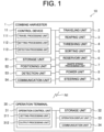
Fig. 1 is a functional block diagram illustrating a configuration of a traveling system according to an embodiment of the present invention. -
Fig. 2 is an external side view illustrating a configuration of a combine harvester according to the embodiment of the present invention. -
Fig. 3 is an external top view illustrating the configuration of the combine harvester according to the embodiment of the present invention. -
Fig. 4 illustrates an example of a target route set in a field according to the embodiment of the present invention. -
Fig. 5 illustrates an example of a work procedure of the combine harvester according to the embodiment of the present invention. -
Fig. 6 illustrates an example of a detection range of each detection unit provided in the combine harvester according to the embodiment of the present invention. -
Fig. 7 illustrates an example of detection information stored in a storage unit of the combine harvester according to the embodiment of the present invention. -
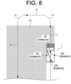
Fig. 8 illustrates an example of a traveling method of the combine harvester according to the embodiment of the present invention. -
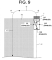
Fig. 9 illustrates an example of the traveling method of the combine harvester according to the embodiment of the present invention. -
Fig. 10 illustrates an example of the traveling method of the combine harvester according to the embodiment of the present invention. -
Fig. 11 illustrates an example of the traveling method of the combine harvester according to the embodiment of the present invention. -
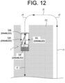
Fig. 12 illustrates an example of the traveling method of the combine harvester according to the embodiment of the present invention. -
Fig. 13 is a flowchart illustrating an example of a procedure of traveling processing executed by a traveling system according to the embodiment of the present invention. -
Fig. 14 illustrates an example of a traveling method of a combine harvester according to another embodiment of the present invention. -
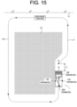
Fig. 15 illustrates an example of a traveling method of a combine harvester according to another embodiment of the present invention. - An embodiment described below is an example embodying the present invention, and does not intend to limit the technical scope of the present invention.
- A
combine harvester 1 is described as an example of the work vehicle of the present invention. As illustrated inFig. 1 , atraveling system 10 according to the embodiment of the present invention includes acombine harvester 1 and anoperation terminal 30. Thecombine harvester 1 and theoperation terminal 30 can communicate with each other via a communication network N1. For example, thecombine harvester 1 and theoperation terminal 30 can communicate via a mobile phone network, a packet network, or a wireless local area network (LAN). - The
combine harvester 1 is a work vehicle that performs agricultural work (an example of a predetermined work of the present invention) such as reaping in a field. The combine harvester 1 works while traveling, and transmits global navigation satellite system (GNSS) information of a GNSS antenna mounted on thecombine harvester 1, that is, the own position of thecombine harvester 1 as measurement point data to theoperation terminal 30. - In addition, the
combine harvester 1 can automatically travel along a preset target route. Thecombine harvester 1 may be configured to automatically travel in a partial area of the field (for example, a straight route) and to manually travel in other areas of the field (for example, a turning route). Thecombine harvester 1 receives various kinds of setting information from theoperation terminal 30, and automatically travels in accordance with the setting information. - The
operation terminal 30 is a portable terminal capable of remotely operating thecombine harvester 1, and is composed of, for example, a tablet terminal, a notebook personal computer, a smart phone, or the like. An operation device similar to theoperation terminal 30 may be provided in thecombine harvester 1. - A worker (operator) can perform the setting operation for various setting items on the
operation terminal 30. Theoperation terminal 30 also displays the information such as a work state, a traveling state, or the like of thecombine harvester 1 during autonomous traveling. The operator can recognize the work state and traveling state at theoperation terminal 30. Theoperation terminal 30 may be omitted in the present invention. -
Fig. 4 illustrates an example of a target route R set for a field F. For example, thecombine harvester 1 performs a reaping work ("round reaping", "reciprocating reaping") in the field F from a start position S to an end position G along the target route R while traveling from the outer peripheral side to the inner peripheral side. Specifically, in an outer peripheral area F1 on the outer peripheral side of the field F, thecombine harvester 1 performs the reaping work while traveling along the edge (outer periphery) of the field. In an inner peripheral area F2 on the inner peripheral side of the field F, thecombine harvester 1 performs the reaping work while traveling straight on each work route in the vertical direction ofFig. 4 , while moving between the work routes by turning and straight traveling without doing the reaping work in the left-right direction. - An example of a work procedure of the
combine harvester 1 is described with reference toFig. 5 . Thecombine harvester 1 starts the automatic travel from the start position S and travels along the outer periphery of the field F while reaping grain culms. The combine harvester 1 threshes the reaped grain culms and externally discharges waste straws such as straw debris from the rear of the machine body to the outside. Accordingly, the waste straws B1 are accumulated in the traveling track of thecombine harvester 1, and a waste straw row is formed on the route where thecombine harvester 1 has finished the reaping work. Thecombine harvester 1 is set to discharge the waste straws of the reaped grain culms at the positions of the grain culms to be reaped, and is configured to grasp positions, a width (a lateral width in the left-right direction of the waste straw row), a length, and the like of thewaste straws B 1. For example, the waste straws B1 are discharged in a width narrower than the lateral width of the machine body with reference to the center in the left-right direction of thecombine harvester 1. - For example, the
combine harvester 1 goes around the outer peripheral area F1 twice. In this case, a waste straw row for two rounds is formed. The number of turns of the outer peripheral area F1 is not limited to two, and may be one or three or more. - After finishing the reaping work of the outer peripheral area F1, the
combine harvester 1 enters the inner peripheral area F2 and starts the reaping work of the inner peripheral area F2. In the inner peripheral area F2, thecombine harvester 1 performs the reaping work in the vertical direction ofFig. 5 while traveling straight on each work route, and moves between the work routes by turning and traveling straight in the outer peripheral area F1 (a work-completed area, a reaped area) without performing the reaping work in the left-right direction. Thecombine harvester 1 performs the reaping work in the inner peripheral area F2, and finishes the automatic traveling and the reaping work when reaching the end position G. - The
combine harvester 1 performs the reaping operation while automatically traveling along the target route R in the field F as described above. Thecombine harvester 1 may be configured to automatically travel without the operator on board, may be configured to automatically travel with the operator on board while receiving an operation from the operator, or may be configured to travel in response to manual steering by the operator (manual travel). Thecombine harvester 1 may also be switchable between the automatic travel mode and the manual travel mode in accordance with a setting operation by the operator. - As illustrated in
Fig. 1 , theoperation terminal 30 is an information processing device including anoperation control unit 31, astorage unit 32, anoperation display unit 33, acommunication unit 34, and the like. Theoperation terminal 30 is composed of, for example, a tablet terminal. - The
communication unit 34 is a communication interface that connects theoperation terminal 30 to the communication network N1 by wire or wirelessly so as to execute data communication in accordance with a predetermined communication protocol with external devices such as one ormore combine harvesters 1 via the communication network N1. - The
operation display unit 33 is a user interface including a display unit, such as a liquid crystal display or an organic electroluminescence (EL) display, that displays various types of information, and an operation unit, such as a touch panel, a mouse, or a keyboard, that accepts operations. On the operation screen displayed on the display unit, the operator can operate the operation unit to perform a registration operation of various types of setting information. The operator can operate the operation unit to provide an automatic travel instruction for thecombine harvester 1. Furthermore, the operator can grasp, at a place distant from thecombine harvester 1, the traveling state of thecombine harvester 1 that automatically travels in the field F, according to the traveling trajectory displayed on theoperation terminal 30. - The
storage unit 32 is a non-volatile storage unit such as a hard disk drive (HDD), a solid state drive (SSD), or a flash memory that stores various types of information. Thestorage unit 32 stores a control program for causing theoperation control unit 31 to execute predetermined control processing. For example, the control program is non-temporarily recorded in a computer-readable recording medium, such as a flash read-only memory (ROM), an electrically erasable programmable read-only memory (EEPROM), a compact disc (CD), or a digital versatile disc (DVD), which is read by a predetermined reading device (not illustrated) provided in theoperation terminal 30 and stored in thestorage unit 32. The control program may be downloaded from a server (not illustrated) to theoperation terminal 30 via the communication network N1 and stored in thestorage unit 32. Thestorage unit 32 may also store the work information transmitted from thecombine harvester 1. - In addition, the
storage unit 32 includes a dedicated application installed for enabling the automatic travel of thecombine harvester 1. Theoperation control unit 31 activates the dedicated application to execute setting processing of various types setting information about thecombine harvester 1, issue an automatic travel instruction to thecombine harvester 1, and the like. - The
operation control unit 31 includes control devices such as a central processing unit (CPU), a read-only memory (ROM), and a random access memory (RAM). The CPU is a processor that executes various types of arithmetic processing. The ROM is a non-volatile storage unit that stores in advance control programs such as a basic input/output system (BIOS) and an operating system (OS) for causing the CPU to execute various types of arithmetic processing. The RAM is a volatile or non-volatile storage unit that stores various pieces of information and is used as a temporary storage memory for the various processing executed by the CPU. Theoperation control unit 31 controls theoperation terminal 30 with the CPU executing various kinds of control programs stored in advance in the ROM or thestorage unit 32. - As illustrated in
Fig. 1 , theoperation control unit 31 includes various types of processing units such as asetting processing unit 311, anoutput processing unit 312, and the like. Theoperation control unit 31 functions as the various processing units by causing the CPU to execute various processing according to the control program. Some or all of the processing units may be composed of an electronic circuit. The control program may be a program that causes a plurality of processors to function as the processing units. - The setting
processing unit 311 sets various kinds of setting information for thecombine harvester 1 to perform automatic traveling. Specifically, the settingprocessing unit 311 sets field information about the field. The field information includes, for example, the shape, size, and position information (coordinates and the like) of the outermost periphery of the field, measurement point data constituting the outermost periphery of the field, and the shape, size, and position information (coordinates and the like) of a work area in the field for performing the work in the field. The field information includes an address of the field, the registered name and date of the field information, the registered name and date of the work area in the field, and the like. The settingprocessing unit 311 accepts the registration operation of the field information by the operator and sets the field information. - The setting
processing unit 311 creates the target route R including the work route and the turning route. For example, the operator selects a route pattern, a turning type, and the like on a setting screen (not illustrated). The route pattern includes the "reciprocating reaping" for reaping a plurality of routes in a reciprocating manner, and the "round reaping" for repeating the reaping of the route along the inner periphery of the work area in the field while shifting the round route toward the center side. On the setting screen, the operator can also correct the turning radius when turning on the work route during the reciprocating reaping and the round reaping. - In addition, the setting
processing unit 311 creates a work route based on the information such as the field information, the route pattern, the turning type, and the turning radius. The settingprocessing unit 311 registers the created work route (target route R) by associating it with the field F. - The setting
processing unit 311 also sets work information regarding work to be performed by thecombine harvester 1. The work information includes information on a reaping work, information on an intermediate work performed by thecombine harvester 1 at a predetermined position during the reaping work, and the like. For example, when the accumulated amount of a reservoir tank 27 (seeFig. 2 ) reaches a predetermined amount (upper limit value) during the reaping work, thecombine harvester 1 moves to a discharge position in the field F and discharges the grain stored in thereservoir tank 27 to a transport vehicle (seeFigs. 14 and15 ). In addition, for example, when the fuel reaches a predetermined amount (lower limit value) during the reaping work, thecombine harvester 1 moves to a refuel position in the field F for refueling. The settingprocessing unit 311 sets the discharge position and the resupply position at any positions in the field F in accordance with the setting operation performed by the operator. The work information includes information such as the upper limit value of the accumulated amount, the discharge position, the lower limit value of the fuel, the refuel position, and the like. - The setting
processing unit 311 sets the traveling speed (vehicle speed) of thecombine harvester 1. For example, the operator can set the straight traveling vehicle speed, the turning vehicle speed, and the rearward vehicle speed for working and non-working conditions on the setting screen. - In addition to the above-described information, the setting
processing unit 311 sets known information such as the type of the combine harvester 1 (the maximum number of rows to be reaped), the vehicle width, the vehicle length, and the like. - The
output processing unit 312 outputs various kinds of setting information set by the settingprocessing unit 311 to thecombine harvester 1. Based on operation by the operator, theoutput processing unit 312 outputs a work start instruction and a work end instruction to thecombine harvester 1. - When the
operation control unit 31 receives the work start instruction operation from the operator, theoutput processing unit 312 outputs the work start instruction to thecombine harvester 1. Accordingly, thecontrol device 11 of thecombine harvester 1 acquires the work start instruction from theoperation terminal 30. Upon acquisition of the work start instruction, thecontrol device 11 starts working and traveling of thecombine harvester 1. When theoperation control unit 31 accepts the operation stop instruction from the operator, theoutput processing unit 312 outputs the work stop instruction to thecombine harvester 1. Accordingly, thecontrol device 11 of thecombine harvester 1 acquires the work stop instruction from theoperation terminal 30. Upon acquisition of the work stop instruction, thecontrol device 11 stops the work and travel of thecombine harvester 1. - The
operation terminal 30 may be accessible to a website of an agricultural support service (agricultural support site) provided by a server (not illustrated) via the communication network N1. In this case, theoperation control unit 31 executes a browser program, allowing theoperation terminal 30 to function as an operating terminal of the server. The server is equipped with the above-described processing units and executes respective processing. -
Fig. 2 is an external view of thecombine harvester 1 when viewed from the side, andFig. 3 is an external view of thecombine harvester 1 when viewed from above. As illustrated inFigs. 1 to 3 , thecombine harvester 1 includes a travelingunit 2, a reapingunit 3, a threshingunit 4, asorting unit 5, areservoir unit 6, a wastestraw processing unit 7, apower unit 8, asteering unit 9, acontrol device 11, astorage unit 51, apositioning unit 52, adetection unit 53, acommunication unit 54, and the like. While traveling by the travelingunit 2, thecombine harvester 1 reaps grain culms by the reapingunit 3, threshes the reaped grain culms by the threshingunit 4, sorts grains by thesorting unit 5, and accumulates the grains in thereservoir unit 6. Thecombine harvester 1 also processes the waste straws after threshing by the wastestraw processing unit 7. Thecombine harvester 1 uses the power supplied from thepower unit 8 to drive the travelingunit 2, the reapingunit 3, the threshingunit 4, thesorting unit 5, thereservoir unit 6, and the wastestraw processing unit 7. - The traveling
unit 2 is provided under amachine body frame 12, and includes a pair of left and right crawler-type traveling device 23 and a transmission (not illustrated). The travelingunit 2 uses the power (for example, the rotational power) transmitted from theengine 20 of thepower unit 8 to rotate the crawlers of the crawler-type traveling device 23, thus traveling thecombine harvester 1 in the front-rear direction or turn in the left-right direction. The transmission transmits the power (rotational power) of thepower unit 8 to the crawler-type traveling device 23 and can also change the speed of the rotational power. - The reaping
unit 3 is a work machine that performs work on the field F to be worked and is provided in front of the travelingunit 2, reaping the grain culms over a predetermined reaping width in an area in which nonreaped grain culms are present, which is an unworked area of the field F (hereinafter referred to as an unreaped area). The reapingunit 3 is an example of a work unit of the present invention. The reapingunit 3 includes adivider 13, a rakingreel 14, a reapingblade 15, a rakingauger 16, afeeder house 17, and atransport conveyor 18. The reapingunit 3 includes a rotation detection unit (not illustrated) that detects a rotation speed (work speed) of a rotation work for performing the reaping work. The rotation detection unit is composed of, for example, a rotation sensor that detects the rotation speed of the rakingreel 14, the rotation speed of the rakingauger 16, and the rotation speed of thetransport conveyor 18. - The
divider 13 is provided to protrude forward from the left front end and the right front end of the reapingunit 3, and guides the grain culms in the unreaped area to put them within the reaping width. The rakingreel 14 is located behind thedivider 13 to be rotatable around a rotation axis extending in the left-right direction. In order to assist reaping of the grain culms guided by thedivider 13, the rakingreel 14 is rotationally driven to rake the ear tip side of the grain culms while raising the grain culms. The reapingblade 15 is disposed under the rakingreel 14 and reaps the grain culms by cutting the culm base side of the grain culms having been raked by the rakingreel 14. - The raking
auger 16 is disposed behind the rakingreel 14 and the reapingblade 15 and is provided rotatably around a rotation axis extending in the left-right direction. The rakingauger 16 is rotationally driven to rake the grain culms having been reaped by the reapingblade 15 and transports the grain culms rearward. - The
feeder house 17 extends forward from themachine body frame 12 to be located behind the rakingauger 16, and is supported by themachine body frame 12 in a manner capable of lifting and lowering. Lifting and lowering thefeeder house 17 causes lifting and lowering of thedivider 13, the rakingreel 14, the reapingblade 15, and the rakingauger 16, that is, the reapingunit 3. - The
combine harvester 1 includes, in themachine body frame 12, a lifting and loweringdevice 19 that causes lifting and lowering of thefeeder house 17 to lift and lower the reapingunit 3, thus lifting and lowering the reapingunit 3 between a working position (seeFig. 2 ) and a non-working position (not illustrated). The lifting and loweringdevice 19 is composed of a hydraulic cylinder or the like that operates upon receipt of power from theengine 20. - The
transport conveyor 18 is provided in a rotatable manner in thefeeder house 17 and moves along with the lifting and lowering of thefeeder house 17. Thetransport conveyor 18 is rotationally driven to transport the grain culms conveyed into thefeeder house 17 by the rakingauger 16 further rearward to the threshingunit 4. - The threshing
unit 4 is provided behind thefeeder house 17 of the reapingunit 3, and threshes the grain culms transported from thefeeder house 17. The threshingunit 4 includes a threshingcylinder 21 and a receivingnet 22. The threshingcylinder 21 threshes grains from grain culms transported from thefeeder house 17, and transports the threshed grain culms, that is, waste straws to the wastestraw processing unit 7. The receivingnet 22 supports the grain culms transported by the threshingcylinder 21, and sieves the grains to let them fall. - The
sorting unit 5 is provided under the threshingunit 4. Thesorting unit 5 includes aswing sorting device 24, ablower sorting device 25, a grain transport device (not illustrated), and a straw debris discharging device (not illustrated). Theswing sorting device 24 sieves the threshed grains fallen from the threshingunit 4 and sorts them into grains, straw debris, and the like. Theblower sorting device 25 further sorts the threshed grains fallen from the threshingunit 4 or the threshed grains sorted by theswing sorting device 24 into grains, straw debris, and the like by blowing air. The grain transport device transports the grains sorted by theswing sorting device 24 and theblower sorting device 25 to thereservoir unit 6. The waste straw discharging device discharges the straw debris and the like other than the grains sorted by theswing sorting device 24 and theblower sorting device 25 to the outside of the machine. - The
reservoir unit 6 is provided on the right side of the threshingunit 4. Thereservoir unit 6 includes a reservoir tank (grain tank) 27 and agrain discharging device 28. Thereservoir tank 27 accumulates the grains transported from thesorting unit 5. Thegrain discharging device 28 includes a discharging auger or the like to perform a discharging work of the grains to discharge the grains accumulated in thereservoir tank 27 to the transport vehicle at a predetermined discharge position. - The waste
straw processing unit 7 is provided behind the threshingunit 4. The wastestraw processing unit 7 includes a waste straw transport device (not illustrated) and a waste straw cutting device (not illustrated). The wastestraw processing unit 7 uses the waste straw transport device to transport the waste straws transported from the threshingunit 4 to the waste straw cutting device, and, after cutting the waste straws by the waste straw cutting device, discharges the cut waste straws to the rear of the combine harvester 1 (seeFig. 5 ). - The
power unit 8 is provided above the travelingunit 2 and below thereservoir unit 6. Thepower unit 8 includes theengine 20 which generates rotational power. Thepower unit 8 transmits the rotational power generated by theengine 20 to the travelingunit 2, the reapingunit 3, the threshingunit 4, thesorting unit 5, thereservoir unit 6, and the wastestraw processing unit 7. Thecombine harvester 1 also includes a fuel tank that stores a fuel to be supplied to theengine 20 of thepower unit 8. - The
steering unit 9 is provided above thepower unit 8. Thesteering unit 9 includes operation devices to steer the travel of thecombine harvester 1 around the driver's seat which is aseat 40 on which the operator sits, such as a steering wheel to provide a turn instruction of the machine body of thecombine harvester 1, and main and auxiliary speed levers to provide a speed change instruction of the forward and rearward travel of thecombine harvester 1. Manual traveling of thecombine harvester 1 is executed by the travelingunit 2 when it accepts operations of the steering wheel and the main and auxiliary speed change levers of thesteering unit 9. Thesteering unit 9 also includes a mechanism for operating the reaping work by the reapingunit 3, the threshing work by the threshingunit 4, the discharging work by thegrain discharging device 28 from thereservoir unit 6, and the like. - The
positioning unit 52 acquires the own position of thecombine harvester 1 using a satellite positioning system such as a global positioning system (GPS) or the like. For example, thepositioning unit 52 receives a positioning signal from a positioning satellite via a positioning antenna, and acquires position information of thepositioning unit 52, that is, the own position of the combine harvester 1 (measurement point data), based on the positioning signal. Thepositioning unit 52 may be composed of a quantum compass instead of the positioning antenna. - The
communication unit 54 is a communication interface for connecting thecombine harvester 1 to the communication network N1 by wire or wirelessly and performing data transmission with external devices such as theoperation terminal 30 via the communication network N1 in accordance with a predetermined communication protocol. - The
storage unit 51 is a non-volatile storage unit such as an HDD, an SSD, or a flash memory that stores various kinds of information. Thestorage unit 51 stores a control program such as a travel program for causing thecontrol device 11 to execute traveling processing (seeFig. 13 ) which will be described later. For example, the travel program is non-transitorily recorded in a computer-readable recording medium such as a flash ROM, an EEPROM, a CD, or a DVD, read by a predetermined reading device (not illustrated), and stored in thestorage unit 51. The travel program may be downloaded from a server (not illustrated) to thecombine harvester 1 via the communication network N1 and stored in thestorage unit 51. Thestorage unit 51 also stores various types of setting information acquired from theoperation terminal 30. - The
detection unit 53 is a sensor that detects a detection target in a predetermined detection range using infrared rays, ultrasonic waves, and the like. For example, thedetection unit 53 may be a lidar sensor (distance sensor) capable of three dimensionally measuring a distance to a measurement target (detection target) using lasers, or may be a sonar sensor including a plurality of sonars capable of measuring a distance to a measurement target using ultrasonic waves. Further, the sonar sensor may not have a function of measuring a distance. As illustrated inFigs. 2 and 3 , thedetection unit 53 includes afront detection unit 53F provided at the front portion of the machine body of thecombine harvester 1, arear detection unit 53B provided at the rear portion of the machine body, a leftside detection unit 53L provided on the left side portion of the machine body, and a rightside detection unit 53R provided on the right side portion of the machine body. Thework vehicle 1 of the present invention may include one detection unit, or may be configured to include a plurality of detection units. In thecombine harvester 1 of the present embodiment, thefront detection unit 53F and therear detection unit 53B are composed of the lidar sensors, and the leftside detection unit 53L and the rightside detection unit 53R are composed of the sonar sensors. Alternatively, however, all of thefront detection unit 53F, therear detection unit 53B, the leftside detection unit 53L, and the rightside detection unit 53R may be composed of the lidar sensors or sonar sensors. - In addition, the
detection unit 53 is configured to be capable of detecting the detection target (for example, a person, an object, a structure, or the like) in a predetermined detection range set in advance. For example, an area to be monitored (a detection range) for controlling the travel of thecombine harvester 1 can be set for thedetection unit 53.Fig. 6 schematically illustrates an example of the detection range of eachdetection unit 53. For example, a detection range AF1 of thefront detection unit 53F and a detection range AB1 of therear detection unit 53B include a stop area closest to thecombine harvester 1, a deceleration area farther from the stop area, and a notification area farther from the deceleration area. For example, the stop area is set in a range of about two meters from thecombine harvester 1, the deceleration area is set in a range of about six meters from the stop area, and the notification area is set in a range of about two meters from the deceleration area. For example, in a detection range AL1 of the leftside detection unit 53L and a detection range AR1 of the rightside detection unit 53R, a stop area is set in a range of two meters from thecombine harvester 1. The deceleration area and a notification area may be set in the detection range of the leftside detection unit 53L and the rightside detection unit 53R. The range of each area may be set according to the vehicle speed of thecombine harvester 1. - The
detection unit 53 transmits the measurement information (detection information) to thecontrol device 11. Thecontrol device 11 determines whether the detection target is an obstacle, while identifying the position of the detection target (obstacle) based on the measurement information acquired from thedetection unit 53. When it is determined that the detection target detected in the notification area during the automatic traveling of thecombine harvester 1 is the obstacle, thecontrol device 11 notifies an alarm externally. When it is determined that the detection target detected in the deceleration area during the automatic traveling of thecombine harvester 1 is the obstacle, thecontrol device 11 decelerates thecombine harvester 1. When it is determined that the detection target detected in the stop area during the automatic traveling of thecombine harvester 1 is the obstacle, thecontrol device 11 stops thecombine harvester 1. Thecontrol device 11 may output position information indicating the identified position of the obstacle to theoperation terminal 30. - Alternatively, the
detection unit 53 may be composed of a camera. For example, thedetection unit 53 analyzes a captured image obtained by imaging the surroundings of thecombine harvester 1 to detect the detection target. Thedetection unit 53 may determine a person, an object, or a work object (grain culms or the like), and thecontrol device 11 may perform notification processing, deceleration processing, stop processing, or the like according to the determination result. Alternatively, thedetection unit 53 may be composed of a lidar sensor and a camera. In this case, thedetection unit 53 detects the detection target based on the captured image and the distance measured by the lidar sensor. Thedetection unit 53 is an example of the detection unit of the present invention. - The
control device 11 includes control devices such as a CPU, a ROM, and a RAM. The CPU is a processor that executes various types of arithmetic processing. The ROM is a non-volatile storage unit that stores in advance control programs such as a BIOS and an OS for causing the CPU to execute various types of arithmetic processing. The RAM is a volatile or non-volatile storage unit that stores various pieces of information and is used as a temporary storage memory for the various processing executed by the CPU. Thecontrol device 11 controls thecombine harvester 1 by causing the CPU to execute various types of control programs stored in advance in the ROM or thestorage unit 51. - In a conventional combine harvester, for example, a predetermined range is removed from the detection target so that the combine harvester does not recognize a work object (for example, grain culms) as the obstacle when traveling in the work area. However, once this processing is applied, the detection target (a person, an object, or the like) included in the predetermined range cannot be appropriately detected as the obstacle when the combine harvester travels in the non-work area or the work-completed area. In contrast, the
work vehicle 1 according to the present embodiment is configured to appropriately detect the detection target as the obstacle as described below. - Specifically, as illustrated in
Fig. 1 , thecontrol device 11 includes various processing units such as atravel processing unit 111, asetting processing unit 112, and adetection processing unit 113. Thecontrol device 11 functions as the various processing units by causing the CPU to execute various processing according to the travel program. Some or all of the processing units may be composed of an electronic circuit. The travel program may be a program that causes a plurality of processors to function as the processing units. - The
travel processing unit 111 executes travel processing for causing thecombine harvester 1 to travel. Specifically, thetravel processing unit 111 causes thecombine harvester 1 to automatically travel along the target route R set for the field F. Thetravel processing unit 111 causes thecombine harvester 1 to travel in accordance with a plurality of work routes on which thecombine harvester 1 is made to perform a predetermined work (reaping work) and transfer routes (for example, turning routes) connecting the plurality of the work routes, both routes included in the target route R. Thetravel processing unit 111 acquires various setting information set for the field F from theoperation terminal 30. In the reaping work, thetravel processing unit 111 acquires the own position of thecombine harvester 1 from thepositioning unit 52, and controls the travelingunit 2, the reapingunit 3, and thepower unit 8 so as to make thecombine harvester 1 perform the automatic travel and the reaping work along the work route based on the own vehicle position and the work route included in the target route R. - For example, as illustrated in
Fig. 5 , thetravel processing unit 111 causes thecombine harvester 1 to automatically travel from the start position S and perform the reaping operation along the outer periphery in the outer peripheral area F1, and then causes thecombine harvester 1 to automatically travel and perform the reaping operation in the inner peripheral area F2 until the end position G. - The setting
processing unit 112 sets the detection function for the detection target to be enabled or disabled based on the target route R (travel route). Here, "enabling the detection function" means using a detection result of detection of the detection target by the detection unit 53 (for example, information of an identification signal indicating that the detection target is detected, or information of a distance to the detection target), that is, using, for example processing of determining whether the detection target is the obstacle, or processing of determining whether to cause thecombine harvester 1 to execute a predetermined countermeasure processing (for example, the notification processing, the deceleration processing, the stop processing, or work interruption). In contrast, "disabling the detection function" means not to use the detection result of detecting the detection target by thedetection unit 53. Specifically, in disabling the detection function, the settingprocessing unit 112 sets, for example, the detection result of thedetection unit 53 to be not used by each processing unit (thetravel processing unit 111, thedetection processing unit 113, and the like). Alternatively, in disabling the detection function, the settingprocessing unit 112 may stop, for example, the operation of the detection unit 53 (for example, the operation of outputting a detection signal such as a laser or an ultrasonic wave), may set the power of thedetection unit 53 to the OFF state, or may not cause thedetection unit 53 to output the detection result of the detection target detected by thedetection unit 53 to thecontrol device 11. - In the present embodiment, for example, the
detection unit 53 transmits the detection result to thecontrol device 11 at a predetermined cycle. Thecontrol device 11 registers the detection result in detection information D1 (seeFig. 7 ). The detection information D1 registers data transmitted from each of the detection units 53 (thefront detection unit 53F, therear detection unit 53B, the leftside detection unit 53L, and the rightside detection unit 53R) at a predetermined cycle (time interval). For example, upon acquisition of the information indicating that the detection target has been detected from thedetection unit 53, thecontrol device 11 registers predetermined identification information (flag "1"). In a case where no information indicating detection of the detection target from thedetection unit 53 or indicating no detection of the detection target from thedetection unit 53 is acquired, thecontrol device 11 registers predetermined identification information ("0"). Thecontrol device 11 registers the identification information ("1", "0") in the detection information D1 from the start to the end of the automatic traveling of thecombine harvester 1. - The
detection processing unit 113 executes predetermined processing based on the detection result of thedetection unit 53. Specifically, when thedetection unit 53 detects a detection target in a case where the detection function is set to be enabled, thedetection processing unit 113 determines that the detection target is an obstacle, and performs a countermeasure processing (notification processing, deceleration processing, stop processing, work interruption, or the like) for the obstacle. Based on the detection information D1 (seeFig. 7 ), thedetection processing unit 113 identifies the time and location (the detection unit that has detected the detection target among thefront detection unit 53F, therear detection unit 53B, the leftside detection unit 53 L, and the rightside detection unit 53R, and the position coordinates of the detection target with respect to the field F) at which the detection target has been detected. - For example, when the
detection unit 53 detects the detection target in the notification area in a state in which the detection function is set to be enabled, thedetection processing unit 113 notifies an alarm externally. When thedetection unit 53 detects the detection target in the deceleration area in a state in which the detection function is set to be enabled, thedetection processing unit 113 decelerates thecombine harvester 1. When thedetection unit 53 detects the detection target in the stop area in a state in which the detection function is set to be enabled, thedetection processing unit 113 stops thecombine harvester 1. Thedetection processing unit 113 may execute different countermeasure processing according to the detection unit 53 (thefront detection unit 53F, therear detection unit 53B, the leftside detection unit 53 L, or the rightside detection unit 53R) that has detected the obstacle. - In contrast, when the
detection unit 53 detects the detection target in a state in which the detection function is set to be disabled, thedetection processing unit 113 does not determine that the detection target is the obstacle and does not perform the countermeasure processing. Specifically, even when the identification information (flag "1") indicating the detection of detection target is registered in the detection information D1, thedetection processing unit 113 ignores this and omits the countermeasure processing. In this case, thetravel processing unit 111 keeps the automatic travel of thecombine harvester 1. - Thus, the
detection processing unit 113 executes processing on the detection target based on the setting state ("enabled" or "disabled") of the detection function and the detection result of thedetection unit 53. - A specific example of a method of setting the detection function is described. For example, when the target route R includes the work route for performing a predetermined work (for example, the reaping work) on the work object (for example, the grain culms), the setting
processing unit 112 sets the detection function to be disabled when thecombine harvester 1 travels on an unworked work route on which the work has not been performed, while setting the detection function to be enabled when thecombine harvester 1 travels on a work-completed work route on which the work has been performed.Fig. 8 illustrates an example of the reaping operation by thecombine harvester 1. As illustrated inFig. 8 , thecombine harvester 1 travels straight in the inner peripheral area F2 while performing the reaping work on the unworked work route r1, lifts the reapingunit 3 and stops the reaping work when leaving the inner peripheral area F2. Then, thecombine harvester 1 travels through the turning route r2, the straight traveling route r3, and the turning route r4, and enters the inner peripheral area F2 where it restarts the reaping work by lowering the reapingunit 3 and travels straight on the work route r5. - On the travel routes described above, as illustrated in
Fig. 8 , when thecombine harvester 1 travels on the unworked work route r1 in a state in which the work objects (grain culms) are present on the front side and the left side of the machine body, and the grain culms are not present on the rear side and the right side of the machine body, the settingprocessing unit 112 sets the detection function corresponding to thefront detection unit 53F and the leftside detection unit 53L to be disabled, while setting the detection function corresponding to therear detection unit 53B and the rightside detection unit 53R to be enabled. Accordingly, for example, when thefront detection unit 53F detects the detection target, thedetection processing unit 113 does not execute the countermeasure processing (the notification processing, the deceleration processing, the stop processing, the work interruption, or the like) for the detection target, allowing thetravel processing unit 111 to keep the automatic travel and the reaping work. This prevents determining the grain culms to be the obstacle and stopping the automatic travel or the like when, for example, thefront detection unit 53F detects the grain culms. On the other hand, for example, when the rightside detection unit 53R detects the detection target, thedetection processing unit 113 determines the detection target to be the obstacle and executes the predetermined countermeasure processing (the notification processing, the deceleration processing, the stop processing, the reaping operation interruption, or the like). This allows appropriately detecting a person, when the person enters, for example, the work-completed area (reaped area) and approaches thecombine harvester 1. - As illustrated in
Fig. 9 , when thecombine harvester 1 finishes the reaping work on the work route r1 and no grain culms are present in front of the machine body, the settingprocessing unit 112 switches the detection function corresponding to thefront detection unit 53F from the disabled state to the enabled state. This allows appropriate detection of the obstacle that is present in front of thecombine harvester 1 immediately after it exits the inner peripheral area F2. When the target route R on which thecombine harvester 1 is traveling is switched from the work route to the non-work route, the settingprocessing unit 112 may switch the detection function from the disabled state to the enabled state before the start position of the non-work route (inFig. 9 , the end of the work route r1). This makes it possible to appropriately detect the obstacle is present near the boundary of the inner peripheral area F2. - As illustrated in
Fig. 10 , when thecombine harvester 1 exits the inner peripheral area F2 and travels on the turning route r2, the grain culms are no longer present on the left side of the machine body, and therefore thesetting processing unit 112 switches the detection function corresponding to the leftside detection unit 53L from the disabled state to the enabled state. This allows appropriate detection of the obstacle that is present on the left side immediately after thecombine harvester 1 exits from the inner peripheral area F2. Thecombine harvester 1 travels in the reaped area (the work-completed area) of the inner peripheral area F2 (the outer peripheral area F1) in a state in which all the detection units 53 (thefront detection unit 53F, therear detection unit 53B, the leftside detection unit 53L, and the rightside detection unit 53R) are set to be enabled. - As illustrated in
Fig. 11 , when thecombine harvester 1 enters the inner peripheral area F2 from the outer peripheral area F1 and the grain culms are present in front of the machine body, the settingprocessing unit 112 switches the detection function corresponding to thefront detection unit 53F from the enabled state to the disabled state. This prevents unintended execution of the countermeasure processing (the notification processing, the deceleration processing, the stopping process, the reaping work interruption, or the like) when thecombine harvester 1 travels and performs the reaping work on the work route r5 and determines the grain culms that are present in front as the obstacle. - As illustrated in
Fig. 12 , when thecombine harvester 1 travels straight on the work route r5 in the inner peripheral area F2 and the grain culms are further present on the left side and the right side of the machine body, the settingprocessing unit 112 switches the detection function corresponding to the leftside detection unit 53L and the rightside detection unit 53R from the enabled state to the disabled state. This prevents unintended execution of the countermeasure processing (the notification processing, the deceleration processing, the stop processing, the reaping work interruption, or the like) when thecombine harvester 1 travels on the work route r5 and performs the reaping work and determines the grain culms that are present on the left side and the right side as the obstacles. - As described above, the
control device 11 sets the detection function for the detection target to be enabled or disabled according to the travel route. Thecontrol device 11 also determines whether to cause thecombine harvester 1 to execute the predetermined countermeasure processing according to the setting state of the detection function. - The
combine harvester 1 according to the present embodiment includes thedetection unit 53 having a detection range in front of thecombine harvester 1 and thedetection unit 53 having a detection range on the side of thecombine harvester 1, and the detection function is set to be enabled or disabled for eachdetection unit 53 based on the target route R. Thecontrol device 11 sets the detection function corresponding to thedetection unit 53 having a detection range covering the unworked work route (unreaped area) adjacent to the work route on which thecombine harvester 1 travels to be disabled, while setting the detection function corresponding to thedetection unit 53 having a detection range covering the work-completed work route (reaped area) adjacent to the work route on which thecombine harvester 1 travels to be disabled. - In the
combine harvester 1 according to the present embodiment, thecontrol device 11 is configured to cause thecombine harvester 1 to execute the predetermined countermeasure processing on the detection target (obstacle) when the detection target is detected in a state in which the detection function is set to be enabled, and not cause thecombine harvester 1 to execute the countermeasure processing when the detection target is detected in a state in which the detection function is set to be disabled. For example, when thedetection unit 53 detects the detection target in a state in which the detection function is set to be enabled, thecontrol device 11 determines the detection target as the obstacle and executes the countermeasure processing (the notification processing, the deceleration processing, the stop processing, the work interruption, or the like) for the obstacle. When thedetection unit 53 detects, for example, the detection target in a state in which the detection function is set to be disabled, thecontrol device 11 does not determine the detection target as the obstacle and omits the countermeasure processing. - Alternatively, for the detection function corresponding to a
certain detection unit 53, when thecombine harvester 1 travels on the unworked work route, the control device 11 (the setting processing unit 112) may set the detection function corresponding to a first predetermined range including the work object to be disabled, and set the detection function corresponding to a second predetermined range not including the work object to be enabled. For example, when thecombine harvester 1 travels on the work route r1 (seeFig. 8 ), the settingprocessing unit 112 sets the detection function to be disabled for a lower region including the grain culms in the detection area of thefront detection unit 53F, and sets the detection function to be enabled for an upper region above the grain culms in the detection area. For example, the settingprocessing unit 112 masks the lower region to omit the detection processing of the lower region. This prevents execution of the countermeasure processing of, for example, the front lower side even when the grain culms are detected there, while allowing execution of the countermeasure processing in the upper side when a person or the like is detected there. In this way, the settingprocessing unit 112 may be able to set the detection function of eachdetection unit 53 to be enabled or disabled for each region within the detection area. - An example of the travel processing executed by the traveling
system 10 is described with reference toFig. 13 . - The present invention can be considered as an invention of a traveling method for executing one or more steps included in the travel processing. One or more steps included in the travel processing described herein may be appropriately omitted. The steps of the travel processing may be executed in a different order to the extent that they produce similar effects and advantages. Although a case where the
control device 11 of thecombine harvester 1 executes the travel processing steps is described herein as an example, a traveling method in which one or more processors execute the travel processing steps in a distributed manner can be considered alternatively. The traveling method corresponding to the travel processing is an example of the detection method of the present invention. - In step S1, the
control device 11 determines whether a work start instruction is acquired. Once the work start instruction is acquired from theoperation terminal 30 or the operation device (the operation lever or the like) of the combine harvester 1 (S1:Yes), thecontrol device 11 shifts the process to step S2. Thecontrol device 11 waits until the work start instruction is acquired (Sl:No). - In step S2, the
control device 11 starts the automatic travel processing. Specifically, thecontrol device 11 causes thecombine harvester 1 to automatically travel along the target route R included in the setting information acquired from theoperation terminal 30. For example, thecontrol device 11 causes thecombine harvester 1 to perform the work (the reaping work) in the field F (seeFig. 4 ) while traveling it automatically along the target route R. Thecontrol device 11 may be able to accept the operation of the main shift lever by the operator who is riding on thecombine harvester 1. In this case, thecontrol device 11 changes the vehicle speed of the automatically travelingcombine harvester 1 according to the operation of the operator. - In step S3, the
control device 11 determines the travel route. For example, thecontrol device 11 determines whether the route on which thecombine harvester 1 travels is the work route in the unworked area (unreaped area), the work route in the work-completed area (reaped area), or the transfer route in a non-work area. The travel route includes a travel route (work route) in which the work is performed and a travel route (transfer route) in which the work is not performed. In addition, thecontrol device 11 determines whether the left route (area) and the right route (area) adjacent to the route on which thecombine harvester 1 travels are the work route of the unworked area (unreaped area), the work route of the work-completed area (reaped area), or the work route of the non-work area. Thecontrol device 11 also identifies the position of thecombine harvester 1 on the route on which thecombine harvester 1 is traveling. - Subsequently, in step S4, the
control device 11 sets the detection function to be enabled or disabled. Specifically, thecontrol device 11 sets the detection function corresponding to each of the detection units 53 (thefront detection unit 53F, therear detection unit 53B, the leftside detection unit 53L, and the rightside detection unit 53R) to be enabled or disabled based on the travel route determined in step S3. - For example, when the
combine harvester 1 travels on the unworked work route r1 (seeFig. 8 ), thecontrol device 11 sets the detection function corresponding to thefront detection unit 53F to be disabled. For example, when thecombine harvester 1 travels on the unworked work route r1 and the travel route adjacent to the left side of the work route r1 is the work route in the unworked area (unreaped area), thecontrol device 11 sets the detection function corresponding to the leftside detection unit 53L to be disabled. - For example, when the
combine harvester 1 travels on the unworked work route r1 and the travel route adjacent to the right side of the work route r1 is the work route in the work-completed area (reaped area) or the transfer route of the non-work area, thecontrol device 11 sets the detection function corresponding to the rightside detection unit 53R to be enabled. For example, when the rear side of thecombine harvester 1 is the work-completed area (reaped area) or the non-work area, thecontrol device 11 sets the detection function corresponding to therear detection unit 53B to be enabled. - In this way, the
control device 11 sets the detection function to be enabled or disabled using the information on the travel route. Thecontrol device 11 switches the detection function from the enabled state to the disabled state or from the disabled state to the enabled state using the information on the travel route (seeFigs. 8 to 12 ). - The
control device 11 executes the travel processing according to the setting state of the detection function. Specifically, when thedetection unit 53 in which the detection function is set to be enabled detects the detection target, thecontrol device 11 determines the detection target to be the obstacle and executes the countermeasure processing (the notification processing, the deceleration processing, the stop processing, the work interruption, or the like) for the obstacle. On the other hand, when thedetection unit 53 with the detection function set to be disabled detects the detection target, thecontrol device 11 does not execute the countermeasure processing. - For example, in the example illustrated in
Fig. 8 , when the rightside detection unit 53R or therear detection unit 53B with its function set to be enabled detects the detection target, thecontrol device 11 determines the detection target to be the obstacle and executes the countermeasure processing (the notification processing, the deceleration processing, the stop processing, the work interruption, or the like) with respect to the obstacle. On the other hand, when thefront detection unit 53F or the leftside detection unit 53L with its detection function set to be disabled detects the detection target, thecontrol device 11 does not determine the detection target as the obstacle, omits the countermeasure processing, and continues the automatic traveling. - In step S5, the
control device 11 determines whether thecombine harvester 1 has reached the end position G (seeFig. 5 ). When it is determined that thecombine harvester 1 has reached the end position G (S5:Yes), thecontrol device 11 ends the travel processing. When it is not determined that thecombine harvester 1 has reached the end position G (S5:No), thecontrol device 11 shifts the processing to step S3. Thecontrol device 11 repeatedly executes the above-described processing until the vehicle reaches the end position G (S5:No). - In this way, the
control device 11 repeatedly executes the above-described processing from the start position S to the end position G to cause thecombine harvester 1 to automatically travel along the target route R, while setting the detection function to be enabled or disabled in accordance with the travel route. - As described above, the
combine harvester 1 according to the present embodiment is configured to detect the detection target around thecombine harvester 1 by thedetection units 53 provided in thecombine harvester 1 that automatically travels along the target route R. Thecombine harvester 1 sets the detection function for the detection target to be enabled or disabled based on the target route R. Specifically, the target route R includes the work route for performing the predetermined work (for example, the reaping work) on the work object (for example, the grain culms). Thecombine harvester 1 sets the detection function to be disabled when traveling on the unworked work route, and sets the detection function to be enabled when traveling on the work-completed work route. - The above configuration prevents, for example, stopping the
combine harvester 1 when thedetection unit 53 detects the grain culms while thecombine harvester 1 is traveling on the unworked work route (during the reaping work) and determines the grain culms to be the obstacle. For example, when thedetection unit 53 detects the detection target in the work-completed work route and determines it to be the obstacle, the predetermined countermeasure processing (the notification processing, the deceleration processing, the stop processing, the work interruption, or the like) is executed. This allows appropriate detection of, for example, a person when the person enters the work-completed area (reaped region) and approaches thecombine harvester 1. This configuration that sets the detection function to be enabled or disabled according to the travel route allows appropriate detection of the detection target as the obstacle. - The present invention is not limited to the embodiment described above. Other embodiments of the present invention are described below.
- The
combine harvester 1 may perform an intermediate work at a predetermined position in the middle of a predetermined work (for example, the reaping operation). For example, the intermediate work includes a discharging work in which thecombine harvester 1 is moved to the discharge position during the reaping work to discharge the grains accumulated in thereservoir tank 27 to the transport vehicle, the refueling work in which thecombine harvester 1 is moved to the refuel position during the reaping work for fueling, and the like.Figs. 14 and15 illustrate an example of the discharge operation. - For example, when the accumulated amount of the
reservoir tank 27 reaches a predetermined amount (upper limit value) during the reaping operation, thetravel processing unit 111 lifts the reapingunit 3 to stop the reaping operation, and causes thecombine harvester 1 to travel on the transfer route r11 from the current position (a work interruption position P1) to the discharge position. In addition, the settingprocessing unit 112 sets the detection function corresponding to eachdetection unit 53 when thecombine harvester 1 travels on the transfer route r11. For example, when thecombine harvester 1 travels in the vicinity of the inner peripheral area F2 in the transfer route r11, the settingprocessing unit 112 sets the detection function corresponding to the leftside detection unit 53L to be disabled, and sets the detection function corresponding to thefront detection unit 53F, therear detection unit 53B, and the rightside detection unit 53R to be enabled. - In many cases, the discharging work, the refueling work, and the like are performed near the outer periphery of the field F. For example, the operator registers the discharge position and the refuel position at predetermined positions near the outer periphery of the field F in advance. Here, when the obstacle (for example, a ridge X1 (see
Fig. 14 )) having a predetermined height from the ground is present in the vicinity of the outer periphery, and thecombine harvester 1 approaches the vicinity of the outer periphery while moving to the discharge position along the transfer route r11, the ridge X1 is detected, causing travel limiting processing such as deceleration or stopping to be executed. - Therefore, when the
combine harvester 1 travels in the vicinity of the outer periphery of the field F, the settingprocessing unit 112 switches the detection function corresponding to thedetection unit 53 on the outer peripheral side (the rightside detection unit 53R in the example illustrated inFig. 14 ) from the enabled state to the disabled state. This prevents the ridge X1 from being determined as the obstacle unnecessarily and restricting travel. Thus, by setting the detection function to be disabled so as to prevent fixed objects which are recognized in advance and do not affect driving safety from being determined as the obstacles, the work efficiency can be improved. - When the
combine harvester 1 arrives at the discharge position and finishes the discharge operation, thetravel processing unit 111 causes thecombine harvester 1 to travel along a return route r12 from the discharge position to the work interruption position P1. When thecombine harvester 1 travels on the return route r12, the settingprocessing unit 112 sets the detection function to be enabled or disabled according to the traveling route. - When the
combine harvester 1 enters the inner peripheral area F2, returns to the work-completed work route, and approaches the work interruption position P1, the settingprocessing unit 112 switches the detection function corresponding to thefront detection unit 53F from the enabled state to the disabled state at a position a predetermined distance L1 before the work interruption position P1 (seeFig. 15 ). Thetravel processing unit 111 also lowers the reapingunit 3 to restart the reaping work at the position a predetermined distance L1 before the work interruption position P1. - As described above, when the target route R on which the
combine harvester 1 is traveling is switched from the work-completed work route to the unworked work route, thecontrol device 11 switches the detection function from the enabled state to the disabled state at the position a predetermined distance before the start position of the unworked work route. - According to the above-described configuration, even when the
combine harvester 1 travels along the transfer route to the predetermined position in order to interrupt the reaping operation and perform the discharging work or the refueling work, the detection function can be set to be enabled or disabled according to the transfer route. This allows the detection of the detection target appropriately as the obstacle. - In another embodiment of the present invention, when the
combine harvester 1 travels on the unworked work route and an adjacent work route next to the unworked work route is an unworked work route, and when thedetection unit 53 having the detection range including the adjacent work route does not detect the work object (grain culms), then thecontrol device 11 may determine that the grain culms have fallen down and cause thecombine harvester 1 to execute predetermined countermeasure processing. For example, in the example illustrated inFig. 8 , the detection function corresponding to the leftside detection unit 53L is set to be disabled, but the leftside detection unit 53L detects the grain culms and transmits the detection information to thecontrol device 11. In this case, for example, when the detection information indicating that the leftside detection unit 53L does not detect the grain culms is transmitted to thecontrol device 11, thecontrol device 11 determines that the grain culms are not present on the left side of thecombine harvester 1. Thus, the grain culms cannot appropriately be recognized because the grain culms have fallen down and deviated from the detection range despite the grain culms are originally present. Therefore, when thecontrol device 11 acquires the detection information indicating that the grain culms are not detected although thecombine harvester 1 travels on the work route of the unworked area (unreaped area), thecontrol device 11 determines that the grain culms are in the fell down state by, for example, stamping down. In this case, thecontrol device 11 executes the countermeasure processing corresponding to the lodged state. For example, thecontrol device 11 switches the vehicle speed of thecombine harvester 1 to a low speed or lowers the height of the reapingunit 3 when thecombine harvester 1 is made to travel in the fell down area. - In another embodiment, the
control device 11 may determine that the grain culms on the left side are in the fell down state when thefront detection unit 53F composed of the lidar sensor detects the grain culms, but the leftside detection unit 53L composed of the sonar sensor does not detect the grain culms. That is, when thecombine harvester 1 travels on the unworked work route and the leftside detection unit 53L or the rightside detection unit 53R does not detect the work object (the grain culms) although thefront detection unit 53F has detected the work object (for example, the grain culms), thecontrol device 11 determines that the work object is fallen down. - In another embodiment of the present invention, the
control device 11 may set the detection function corresponding to eachdetection unit 53 to be enabled or disabled according to the setting operation by the operator. For example, the operator may be able to set the detection function to be enabled or disabled for each of thefront detection unit 53F, therear detection unit 53B, the leftside detection unit 53L, and the rightside detection unit 53R on the operation screen of theoperation terminal 30. - The work vehicle of the present invention may be the work vehicle that automatically travels (is automatically steered) on the work route (for example, the straight route) and manually travels (is manually steered) on the turning route, or may be the work vehicle that manually travels (is manually steered) on the work route and automatically travels (is automatically steered) on the turning route.
- Hereinafter, a summary of the invention extracted from the embodiments is described. Configurations and processing functions described in the appendices below may be selected, omitted, or combined as appropriate.
- A detection method for detecting a detection target around a work vehicle that automatically travels along a target route using a detection unit provided in the work vehicle, including
executing setting of a detection function for the detection target to be enabled or disabled based on the target route. - The detection method according to
appendix 1, in which - the target route includes a work route for performing a predetermined work on a work object,
- the detection function is set to be disabled when the work vehicle travels on an unworked work route, and
- the detection function is set to be enabled when the work vehicle travels on a work-completed work route.
- The detection method according to
appendix 2, in which
when the target route on which the work vehicle is traveling is switched from the work-completed work route to the unworked work route, the detection function is switched from an enabled state to a disabled state at a position a predetermined distance before a start position of the unworked work route. - The detection method according to any one of
appendices 1 to 3, in which - the target route includes the work route on which a predetermined work is performed for the work object,
- the work vehicle includes the detection unit having a detection range for detecting the front of the work vehicle, and the detection unit having a detection range for detecting the side of the work route, and
- the detection function is set to be enabled or disabled for each detection unit based on the target route.
- The detection method according to
appendix 4, in which - the detection function corresponding to the detection unit having the detection range covering the unworked work route adjacent to the work route on which the work vehicle travels is set to be disabled, and
- the detection function corresponding to the detection unit having the detection range covering the work-completed work route adjacent to the work route on which the work vehicle travels is set to be enabled.
- The detection method according to
appendix
for the detection function corresponding to one detection unit, when the work vehicle travels on the unworked work route, the detection function corresponding to a first predetermined range including the work object is set to be disabled, and the detection function corresponding to a second predetermined range including no work object is set to be enabled. - The detection method according to any one of
appendices 4 to 6, in which
when the work vehicle travels on the unworked work route and an adjacent work route adjacent to the work route is the unworked work route, and when the detection unit having the detection range covering the adjacent work route detects no work object, it is determined that the work object has fallen down, and the work vehicle is caused to execute predetermined processing. - The detection method according to any one of
appendices 1 to 7, in which - when the detection function is set to be enabled and the detection target is detected, the work vehicle is caused to execute the predetermined processing for the detection target, and
- when the detection function is set to be disabled and the detection target is detected, the work vehicle is caused to execute no predetermined processing.
-
- 1 Combine harvester (work vehicle)
- 2 Traveling unit
- 3 Reaping unit
- 4 Threshing unit
- 5 Sorting unit
- 6 Reservoir unit
- 7 Waste straw processing unit
- 8 Power unit
- 9 Steering unit
- 10 Traveling system
- 11 Control device
- 13 Divider
- 14 Positioning
- 51 Storage unit
- 52 Positioning unit
- 53 Detection unit
- 53F Front detection unit
- 53B Rear detection unit
- 53L Left side detection unit
- 53R Right side detection unit
- 54 Communication unit
- 111 Travel processing unit
- 112 Setting processing unit
- 113 Detection processing unit
- F Field
- R Target route
Claims (10)
- A detection method for detecting a detection target around a work vehicle that automatically travels along a target route using a detection unit provided in the work vehicle, comprising:
executing setting of a detection function for the detection target to be enabled or disabled based on the target route. - The detection method according to claim 1, whereinthe target route includes a work route for performing a predetermined work on a work object,the detection function is set to be disabled when the work vehicle travels on an unworked work route, and the detection function is set to be enabled when the work vehicle travels on a work-completed work route.
- The detection method according to claim 2, wherein
when the target route on which the work vehicle is traveling is switched from the work-completed work route to the unworked work route, the detection function is switched from an enabled state to a disabled state at a position a predetermined distance before a start position of the unworked work route. - The detection method according to claim 1, whereinthe target route includes a work route on which a predetermined work is performed for a work object,the work vehicle includes the detection unit having a detection range for detecting the front of the work vehicle, and the detection unit having a detection range for detecting the side of the work route, andthe detection function is set to be enabled or disabled for each detection unit based on the target route.
- The detection method according to claim 4, whereinthe detection function corresponding to the detection unit having the detection range covering the unworked work route adjacent to the work route on which the work vehicle travels is set to be disabled, andthe detection function corresponding to the detection unit having the detection range covering the work-completed work route adjacent to the work route on which the work vehicle travels is set to be enabled.
- The detection method according to claim 4, wherein
for the detection function corresponding to one detection unit, when the work vehicle travels on the unworked work route, the detection function corresponding to a first predetermined range including the work object is set to be disabled, and the detection function corresponding to a second predetermined range including no work object is set to be enabled. - The detection method according to claim 4, wherein
when the work vehicle travels on the unworked work route and an adjacent work route adjacent to the work route is the unworked work route, and when the detection unit having the detection range covering the adjacent work route detects no work object, it is determined that the work object has fallen down, and the work vehicle is caused to execute predetermined processing. - The detection method according to any one of claims 1 to 7, whereinwhen the detection function is set to be enabled and the detection target is detected, the work vehicle is caused to execute a predetermined processing for the detection target, andwhen the detection function is set to be disabled and the detection target is detected, the work vehicle is caused to execute no predetermined processing.
- A detection program for detecting a detection target around a work vehicle that automatically travels along a target route using a detection unit provided in the work vehicle, wherein
the detection program causes one or more processors to execute setting of the detection function for the detection target to be enabled or disabled based on the target route. - A work vehicle including a detection unit capable of detecting a surrounding detection target and automatically traveling along a target route, comprising:a setting processing unit that sets a detection function for the detection object to be enabled or disabled based on the target route, anda detection processing unit that causes the work vehicle to execute predetermined processing for the detection target in accordance with a setting state of the detection function.
Applications Claiming Priority (1)
| Application Number | Priority Date | Filing Date | Title |
|---|---|---|---|
| JP2023085270A JP2024168520A (en) | 2023-05-24 | 2023-05-24 | DETECTION METHOD, DETECTION PROGRAM, AND WORK VEHICLE |
Publications (1)
| Publication Number | Publication Date |
|---|---|
| EP4468037A1 true EP4468037A1 (en) | 2024-11-27 |
Family
ID=91081964
Family Applications (1)
| Application Number | Title | Priority Date | Filing Date |
|---|---|---|---|
| EP24175729.3A Pending EP4468037A1 (en) | 2023-05-24 | 2024-05-14 | Detection method, detection program, and work vehicle |
Country Status (5)
| Country | Link |
|---|---|
| US (1) | US20240393803A1 (en) |
| EP (1) | EP4468037A1 (en) |
| JP (1) | JP2024168520A (en) |
| KR (1) | KR20240169513A (en) |
| CN (1) | CN119014205A (en) |
Citations (4)
| Publication number | Priority date | Publication date | Assignee | Title |
|---|---|---|---|---|
| US20170131722A1 (en) * | 2014-03-28 | 2017-05-11 | Yanmar Co., Ltd. | Autonomous travelling service vehicle |
| US20190384323A1 (en) * | 2018-06-14 | 2019-12-19 | Sharp Kabushiki Kaisha | Traveling apparatus, travel control method of traveling apparatus, and recording medium |
| JP2021185852A (en) | 2020-06-02 | 2021-12-13 | ヤンマーホールディングス株式会社 | Combine-harvester |
| JP2022088097A (en) * | 2020-12-02 | 2022-06-14 | ヤンマーホールディングス株式会社 | Self-driving system, self-driving method, and self-driving program |
-
2023
- 2023-05-24 JP JP2023085270A patent/JP2024168520A/en active Pending
-
2024
- 2024-05-06 US US18/656,510 patent/US20240393803A1/en active Pending
- 2024-05-08 KR KR1020240060537A patent/KR20240169513A/en active Pending
- 2024-05-14 EP EP24175729.3A patent/EP4468037A1/en active Pending
- 2024-05-22 CN CN202410638000.8A patent/CN119014205A/en active Pending
Patent Citations (4)
| Publication number | Priority date | Publication date | Assignee | Title |
|---|---|---|---|---|
| US20170131722A1 (en) * | 2014-03-28 | 2017-05-11 | Yanmar Co., Ltd. | Autonomous travelling service vehicle |
| US20190384323A1 (en) * | 2018-06-14 | 2019-12-19 | Sharp Kabushiki Kaisha | Traveling apparatus, travel control method of traveling apparatus, and recording medium |
| JP2021185852A (en) | 2020-06-02 | 2021-12-13 | ヤンマーホールディングス株式会社 | Combine-harvester |
| JP2022088097A (en) * | 2020-12-02 | 2022-06-14 | ヤンマーホールディングス株式会社 | Self-driving system, self-driving method, and self-driving program |
Also Published As
| Publication number | Publication date |
|---|---|
| KR20240169513A (en) | 2024-12-03 |
| JP2024168520A (en) | 2024-12-05 |
| US20240393803A1 (en) | 2024-11-28 |
| CN119014205A (en) | 2024-11-26 |
Similar Documents
| Publication | Publication Date | Title |
|---|---|---|
| JP6755117B2 (en) | combine | |
| WO2019124174A1 (en) | Combine control system, combine control program, recording medium with combine control program recorded therein, combine control method, harvester control system, harvester control program, recording medium with harvester control program recorded therein, and harvester control method | |
| KR20210039398A (en) | Harvester, surrounding situation detection system, surrounding situation detection program, recording medium recording the surrounding situation detection program, and surrounding situation detection method | |
| US20240016074A1 (en) | Work vehicle and method for generating agricultural field external shape | |
| JP7555250B2 (en) | Combine harvester and automatic operation method | |
| JP7506970B2 (en) | Yield map creation device | |
| US20240393803A1 (en) | Detection Method, Detection Program, And Work Vehicle | |
| US20230403976A1 (en) | Autonomous travel method, autonomous travel system, and autonomous travel program | |
| JP2021012463A (en) | Work management device and work management system | |
| JP7548802B2 (en) | Arrival information setting method and combine | |
| JP2024168519A (en) | Traveling method, travelling program, and work vehicle | |
| US20240016087A1 (en) | Combine and travel control method | |
| US20260111035A1 (en) | Autonomous travel method, autonomous travel program, and autonomous travel system | |
| US20260020512A1 (en) | Autonomous travel method, autonomous travel program, and autonomous travel system | |
| JP2024173795A (en) | Discharge method, discharge program, discharge system, and work vehicle | |
| JP2025149767A (en) | Discharge method, discharge program, discharge system, and work vehicle | |
| EP4733879A1 (en) | Route generation method, route generation program, and route generation system | |
| CN120560239A (en) | Operation control method, operation control program, and operation control system | |
| US20230413727A1 (en) | Autonomous travel method, autonomous travel system, and autonomous travel program | |
| CN119111233A (en) | Driving method, driving program, and driving system | |
| JP2024118489A (en) | Motion control method, motion control system, and motion control program | |
| JP2024177765A (en) | Route generation method, route generation program, and route generation system | |
| JP2024177766A (en) | Route generation method, route generation program, and route generation system | |
| JP2025009899A (en) | Autonomous driving method, automatic driving program, and automatic driving system | |
| JP2025100238A (en) | Driving Management System |
Legal Events
| Date | Code | Title | Description |
|---|---|---|---|
| PUAI | Public reference made under article 153(3) epc to a published international application that has entered the european phase |
Free format text: ORIGINAL CODE: 0009012 |
|
| STAA | Information on the status of an ep patent application or granted ep patent |
Free format text: STATUS: THE APPLICATION HAS BEEN PUBLISHED |
|
| AK | Designated contracting states |
Kind code of ref document: A1 Designated state(s): AL AT BE BG CH CY CZ DE DK EE ES FI FR GB GR HR HU IE IS IT LI LT LU LV MC ME MK MT NL NO PL PT RO RS SE SI SK SM TR |
|
| STAA | Information on the status of an ep patent application or granted ep patent |
Free format text: STATUS: REQUEST FOR EXAMINATION WAS MADE |
|
| 17P | Request for examination filed |
Effective date: 20250522 |
|
| RIC1 | Information provided on ipc code assigned before grant |
Ipc: G01S 17/931 20200101AFI20250925BHEP Ipc: G05D 1/242 20240101ALI20250925BHEP Ipc: G05D 1/648 20240101ALI20250925BHEP Ipc: G05D 105/15 20240101ALI20250925BHEP Ipc: G05D 107/20 20240101ALI20250925BHEP Ipc: G05D 109/10 20240101ALI20250925BHEP |
|
| STAA | Information on the status of an ep patent application or granted ep patent |
Free format text: STATUS: EXAMINATION IS IN PROGRESS |
|
| 17Q | First examination report despatched |
Effective date: 20251113 |