EP4468024A1 - Aesa-basierte synthetische nullstellung zur verbesserten radarbodenstörungsunterdrückung - Google Patents
Aesa-basierte synthetische nullstellung zur verbesserten radarbodenstörungsunterdrückung Download PDFInfo
- Publication number
- EP4468024A1 EP4468024A1 EP24177252.4A EP24177252A EP4468024A1 EP 4468024 A1 EP4468024 A1 EP 4468024A1 EP 24177252 A EP24177252 A EP 24177252A EP 4468024 A1 EP4468024 A1 EP 4468024A1
- Authority
- EP
- European Patent Office
- Prior art keywords
- null
- signals
- return signals
- esa
- processor
- Prior art date
- Legal status (The legal status is an assumption and is not a legal conclusion. Google has not performed a legal analysis and makes no representation as to the accuracy of the status listed.)
- Pending
Links
Images

Classifications
-
- G—PHYSICS
- G01—MEASURING; TESTING
- G01S—RADIO DIRECTION-FINDING; RADIO NAVIGATION; DETERMINING DISTANCE OR VELOCITY BY USE OF RADIO WAVES; LOCATING OR PRESENCE-DETECTING BY USE OF THE REFLECTION OR RERADIATION OF RADIO WAVES; ANALOGOUS ARRANGEMENTS USING OTHER WAVES
- G01S7/00—Details of systems according to groups G01S13/00, G01S15/00, G01S17/00
- G01S7/02—Details of systems according to groups G01S13/00, G01S15/00, G01S17/00 of systems according to group G01S13/00
- G01S7/023—Interference mitigation, e.g. reducing or avoiding non-intentional interference with other HF-transmitters, base station transmitters for mobile communication or other radar systems, e.g. using electro-magnetic interference [EMI] reduction techniques
- G01S7/0233—Avoidance by phase multiplex
-
- G—PHYSICS
- G01—MEASURING; TESTING
- G01S—RADIO DIRECTION-FINDING; RADIO NAVIGATION; DETERMINING DISTANCE OR VELOCITY BY USE OF RADIO WAVES; LOCATING OR PRESENCE-DETECTING BY USE OF THE REFLECTION OR RERADIATION OF RADIO WAVES; ANALOGOUS ARRANGEMENTS USING OTHER WAVES
- G01S7/00—Details of systems according to groups G01S13/00, G01S15/00, G01S17/00
- G01S7/02—Details of systems according to groups G01S13/00, G01S15/00, G01S17/00 of systems according to group G01S13/00
- G01S7/28—Details of pulse systems
- G01S7/2813—Means providing a modification of the radiation pattern for cancelling noise, clutter or interfering signals, e.g. side lobe suppression, side lobe blanking, null-steering arrays
-
- G—PHYSICS
- G01—MEASURING; TESTING
- G01S—RADIO DIRECTION-FINDING; RADIO NAVIGATION; DETERMINING DISTANCE OR VELOCITY BY USE OF RADIO WAVES; LOCATING OR PRESENCE-DETECTING BY USE OF THE REFLECTION OR RERADIATION OF RADIO WAVES; ANALOGOUS ARRANGEMENTS USING OTHER WAVES
- G01S7/00—Details of systems according to groups G01S13/00, G01S15/00, G01S17/00
- G01S7/02—Details of systems according to groups G01S13/00, G01S15/00, G01S17/00 of systems according to group G01S13/00
- G01S7/023—Interference mitigation, e.g. reducing or avoiding non-intentional interference with other HF-transmitters, base station transmitters for mobile communication or other radar systems, e.g. using electro-magnetic interference [EMI] reduction techniques
-
- G—PHYSICS
- G01—MEASURING; TESTING
- G01S—RADIO DIRECTION-FINDING; RADIO NAVIGATION; DETERMINING DISTANCE OR VELOCITY BY USE OF RADIO WAVES; LOCATING OR PRESENCE-DETECTING BY USE OF THE REFLECTION OR RERADIATION OF RADIO WAVES; ANALOGOUS ARRANGEMENTS USING OTHER WAVES
- G01S7/00—Details of systems according to groups G01S13/00, G01S15/00, G01S17/00
- G01S7/02—Details of systems according to groups G01S13/00, G01S15/00, G01S17/00 of systems according to group G01S13/00
- G01S7/023—Interference mitigation, e.g. reducing or avoiding non-intentional interference with other HF-transmitters, base station transmitters for mobile communication or other radar systems, e.g. using electro-magnetic interference [EMI] reduction techniques
- G01S7/0236—Avoidance by space multiplex
-
- G—PHYSICS
- G01—MEASURING; TESTING
- G01S—RADIO DIRECTION-FINDING; RADIO NAVIGATION; DETERMINING DISTANCE OR VELOCITY BY USE OF RADIO WAVES; LOCATING OR PRESENCE-DETECTING BY USE OF THE REFLECTION OR RERADIATION OF RADIO WAVES; ANALOGOUS ARRANGEMENTS USING OTHER WAVES
- G01S7/00—Details of systems according to groups G01S13/00, G01S15/00, G01S17/00
- G01S7/02—Details of systems according to groups G01S13/00, G01S15/00, G01S17/00 of systems according to group G01S13/00
- G01S7/28—Details of pulse systems
- G01S7/285—Receivers
- G01S7/292—Extracting wanted echo-signals
-
- G—PHYSICS
- G01—MEASURING; TESTING
- G01S—RADIO DIRECTION-FINDING; RADIO NAVIGATION; DETERMINING DISTANCE OR VELOCITY BY USE OF RADIO WAVES; LOCATING OR PRESENCE-DETECTING BY USE OF THE REFLECTION OR RERADIATION OF RADIO WAVES; ANALOGOUS ARRANGEMENTS USING OTHER WAVES
- G01S7/00—Details of systems according to groups G01S13/00, G01S15/00, G01S17/00
- G01S7/02—Details of systems according to groups G01S13/00, G01S15/00, G01S17/00 of systems according to group G01S13/00
- G01S7/40—Means for monitoring or calibrating
- G01S7/4004—Means for monitoring or calibrating of parts of a radar system
- G01S7/4026—Antenna boresight
Definitions
- Radar systems are used for a variety of applications, including detecting and tracking objects in the air or on the ground.
- radar signals can be affected by noise and interference, which can make it difficult to accurately detect objects of interest.
- One way to address this issue is to use nulls, which are areas of reduced or eliminated signal strength that can be used to suppress noise and interference.
- AESA electronically scanned array
- embodiments of the inventive concepts disclosed herein are directed to a radar system that uses multiple nulls to improve detection capabilities. Multiple radar pulses are transmitted and / or received with a different null pattern. The returns from each pulse are averaged together to form a null window that is less noisy and potentially wider than a single null pattern. This approach can improve the signal-to-noise ratio and make it easier to detect objects of interest.
- the system may generate individual pulses from an AESA divided into several subarrays. Each subarray produces a pulse with a null in a different location in the radiation pattern centered about a location of interest.
- the contemporaneous return signals are either summed together in complex numbers, utilizing both amplitude and phase information of the far-field radiation pattern, or alternately averaged together.
- inventive concepts are not limited in their application to the arrangement of the components or steps or methodologies set forth in the following description or illustrated in the drawings.
- inventive concepts disclosed herein may be practiced without these specific details.
- well-known features may not be described in detail to avoid unnecessarily complicating the instant disclosure.
- inventive concepts disclosed herein are capable of other embodiments or of being practiced or carried out in various ways. Also, it is to be understood that the phraseology and terminology employed herein is for the purpose of description and should not be regarded as limiting.
- a letter following a reference numeral is intended to reference an embodiment of a feature or element that may be similar, but not necessarily identical, to a previously described element or feature bearing the same reference numeral (e.g., 1, 1a, 1b).
- reference numeral e.g. 1, 1a, 1b
- Such shorthand notations are used for purposes of convenience only, and should not be construed to limit the inventive concepts disclosed herein in any way unless expressly stated to the contrary.
- any reference to "one embodiment,” or “some embodiments” means that a particular element, feature, structure, or characteristic described in connection with the embodiment is included in at least one embodiment of the inventive concepts disclosed herein.
- the appearances of the phrase “in at least one embodiment” in the specification does not necessarily refer to the same embodiment.
- Embodiments of the inventive concepts disclosed may include one or more of the features expressly described or inherently present herein, or any combination or sub-combination of two or more such features.
- embodiments of the inventive concepts disclosed herein are directed to a radar system that uses multiple nulls to improve detection capabilities.
- Radar systems side lobe levels are described as 2-way side lobes, which is a figure of merit that adds the transmit and received far field radiation patterns together as a single pattern.
- the 2-way radar side lobe patterns can be altered by changing only the transmit pattern, or only the receive pattern, or both.
- 2-way side lobe patterns are changed synchronously by changing Tx patterns, Rx patterns, or both. For example, Multiple radar pulses are transmitted and / or received with a different null pattern.
- An aggregate null can be generated through a series of transmit pulses, each with different null locations received in time sync with the radar receiver and coherently added together to realize enhanced null depths or widths in the far field radiation pattern.
- the receive pattern remains fixed for each of the different transmit pulses.
- Another approach is to fix the transmit far field pattern for each pulse and adjust nulls in the receive pattern for each pulse in a time synchronized manner. In this case the pattern summing, or averaging is performed on the receive pulses.
- Both the per pulse transmit radiation patterns and the per pulse receive radiation patterns can have unique nulls by means of time synced Tx and Rx pulse epochs to effectively enhance both the Tx 1-way and Rx 1- way radiation patterns to time synchronously and simultaneously sum or average both multi-pulse Tx patterns and multi-pulse Rx patterns to realize a superior 2-way null for ground clutter suppression.
- the returns from each pulse are averaged together to form a null window that is less noisy and potentially wider than a single null pattern. This approach can improve the signal-to-noise ratio and make it easier to detect objects of interest.
- the system may generate individual pulses from an AESA divided into several subarrays.
- Each subarray produces a pulse with a null in a different location in the radiation pattern centered about a location of interest.
- the contemporaneous return signals are averaged together.
- the use of multiple pulses (Tx-only, Rx-only, or the combination of Tx and Rx pulses), each with different null positions, as described above for the full AESA aperture, can be implement at the individual subarray level as well, and then a multiple pulse aggregate or average full-aperture 2-way radiation pattern can be created by combining the individual subarray patterns.
- the system includes a processor 100 and memory 102 for embodying processor executable code to electronically configure an ESA antenna 104 to produce a desired radiation pattern, either for transmit (Tx) or receive (Rx).
- the processor 100 receives or identifies a location in the radiation pattern where a null is desirable; for example, a location corresponding to ground clutter or other interference.
- the processor 100 may be embodied in a radar system and comprise a transmitter, a receiver, and a digital signal processor (DSP).
- the transmitter generates radar pulses that are transmitted into the environment, and the receiver collects the return signals from those pulses.
- the processor 100 may be embodied in a field programmable gate array, system-on-a-chip, or other appropriate solid-state electronics. Such processing may reduce the time required to integrate and synthesize the null window as described herein.
- the processor 100 determines multiple electronic configurations for the ESA antenna 104, each including a null in a portion of the radiation pattern at or near the location. Each null may be narrower and deeper than any single null would be covering the entire desired location. The processor 100 then applies those configurations to the ESA antenna 104 in successive pulses, and receives corresponding return signals.
- the return signals may be stored in a data storage device 106 until all of the return signals are received, then combined together to produce a composite return signal. Alternatively, the return signals may be combined in real-time as the return signals are received.
- the composite return signal may have a composite null window with less noise than would be possible with a single radiation pattern having a null over the entire desired location. Noise is generally randomized so measurements in the null window over time may reduce noise or facilitate noise filtering.
- each null may be deeper and / or wider in angular extent than a single null covering the entire desired location, the return signal would have correspondingly less noise within the null window. Combining the return signals may therefore result in a composite signal with less noise over the entire desired location.
- the null window can be used in any suitable way to suppress noise and interference in radar signals.
- the null window can be applied to the received signals to suppress noise and interference in real-time, or it can be used to process stored radar data to improve detection capabilities retrospectively.
- the processor 100 may combine the return signals via direct complex addition, simple averaging, weighted averaging, or some other function operating on the return signals, including a trained AI algorithm. For example, the processor 100 may apply certain weightings based on the known desired location and width of the null window, and the actual location and width of each null in the corresponding pulse. In at least one embodiment, filtering may be applied to individual return signals before combining into a composite signal.
- the processor 100 may electronically separate the ESA antenna 104 into a plurality of subarrays 108, 110, 112, 114. The processor 100 may then electronically configure each subarray 108, 110, 112, 114 to produce a distinct radiation pattern either during Tx, Rx, or both, each having a null in a different location proximal to the desired location. The entire ESA antenna 104 may then be driven to contemporaneously produce a plurality of pulses that are substantially similar except with nulls in slightly different positions in the radiation pattern when applied during transmission. In at least one embodiment, the processor 100 receives the contemporaneous return signals and perform operations to produce a composite return signal. Alternatively, or in addition, the contemporaneous return signals may combine via constructive and destructive interference.
- the processor 100 may determine the desired location for a null with reference to a known source of interference or ground clutter; for example, via a set of known interference or ground clutter sources stored in the data storage device 106. Alternatively, or in addition, the processor 100 may determine that a null is desirable based on certain characteristics of prior return signals (characteristics indicative of interference or ground clutter as opposed to actual targets of interest). Furthermore, the processor 100 may apply a null at the desirable location, and subsequently determine that the null is insufficient based a threshold level of noise in a return signal. The processor 100 may then determine a set of deeper, narrower nulls to apply to subsequent signals as described herein.
- a null may be generated in a full aperture monopulse TX sum beam and also is the azimuth difference beam and / or the elevation difference beam.
- the processor 100 may then digitally process the delta elevation and delta azimuth values in a phase monopulse manner.
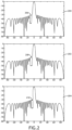
- radiation patterns 200, 202, 204 with nulls 206, 208, 210 are shown.
- the radiation patterns 200, 202, 204 may be generated by an ESA sequentially, and the return signals stored and combined to form a composite with a null window defined by averaging or other combination of the nulls 206, 208, 210. This process can happen in Rx, Tx or both.
- a single ESA may be electronically divided into subarrays and one of the radiation patterns 200, 202, 204 generated contemporaneously by a corresponding subarray.
- the nulls 206, 208, 210 may be defined with respect to a center point and / or some boundary of a desired null window. Each null 206, 208, 210 may typically vary by three to five degrees from the center point.
- a target null may be six degrees wide with a depth of -50 dBi, eight degrees off the main lode.
- a system according to the present disclosure may produce three separate radiation patterns 200, 202, 204, each with a null 206, 208, 210 five degrees wide with a depth of -50 dBi.
- a first null 206 may be ten degrees off the main lobe
- a second null 208 may be eight degrees off the main lobe
- a third null 210 may be six degrees off the main lobe.
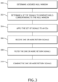
- a processor in a radar system may determine 300 or receive a desired null window.
- the null window may be determined with reference to known interference or ground clutter sources, or via analysis of prior radar return signals.
- the processor determines 302 a set of signals to apply to an ESA, (transmit, receive, or both) to produce nulls corresponding to the null window (within boundaries defined by the null window or offset from some central reference point defined by the null window).
- the signals are applied 304 to an ESA, either sequentially across the entire aperture, either Tx, Rx, or both, or by dividing the ESA into subarrays and applying a separate signal to each subarray, again, either Tx, Rx, or both.
- the ESA receives 306 one or more return signals that are then combined 310 to form a composite null window.
- each return signal may be filtered 308 separately prior to combining 310.
- the system can generate a null window that is less noisy and potentially wider than a single null pattern. This can improve the signal-to-noise ratio and make it easier to detect objects of interest.
- the synthesis and application of less noisy, wider nulls is paramount for advanced ground clutter suppression techniques and will enhance AESA operations in windshear modes, producing accuracy at least as comparable to mechanical radars.
Landscapes
- Engineering & Computer Science (AREA)
- Radar, Positioning & Navigation (AREA)
- Remote Sensing (AREA)
- Computer Networks & Wireless Communication (AREA)
- Physics & Mathematics (AREA)
- General Physics & Mathematics (AREA)
- Radar Systems Or Details Thereof (AREA)
Applications Claiming Priority (1)
| Application Number | Priority Date | Filing Date | Title |
|---|---|---|---|
| US18/200,900 US12546855B2 (en) | 2023-05-23 | 2023-05-23 | AESA-based synthetic nulling for enhanced radar ground clutter suppression |
Publications (1)
| Publication Number | Publication Date |
|---|---|
| EP4468024A1 true EP4468024A1 (de) | 2024-11-27 |
Family
ID=91226867
Family Applications (1)
| Application Number | Title | Priority Date | Filing Date |
|---|---|---|---|
| EP24177252.4A Pending EP4468024A1 (de) | 2023-05-23 | 2024-05-22 | Aesa-basierte synthetische nullstellung zur verbesserten radarbodenstörungsunterdrückung |
Country Status (2)
| Country | Link |
|---|---|
| US (1) | US12546855B2 (de) |
| EP (1) | EP4468024A1 (de) |
Citations (3)
| Publication number | Priority date | Publication date | Assignee | Title |
|---|---|---|---|---|
| EP1267444A2 (de) * | 2001-06-15 | 2002-12-18 | Lockheed Martin Corporation | Digitale adaptive Subarray-Strahlformung und deterministische Summen-und Differenz-Strahlformung mit Störungsauslöschung und Aufrechterhaltung des Monopulsverhältnisses |
| US20220397662A1 (en) * | 2020-12-31 | 2022-12-15 | Src, Inc. | Angle diversity multiple input multiple output radar |
| EP4174514A1 (de) * | 2021-11-02 | 2023-05-03 | Rockwell Collins, Inc. | Aesa-tx-impulspaar-strahlungsmusterphasenkonjugation für ein strahlungsmuster mit niedriger nebenkeule / maximaler eirp |
Family Cites Families (10)
| Publication number | Priority date | Publication date | Assignee | Title |
|---|---|---|---|---|
| US6075484A (en) * | 1999-05-03 | 2000-06-13 | Motorola, Inc. | Method and apparatus for robust estimation of directions of arrival for antenna arrays |
| US8264405B2 (en) | 2008-07-31 | 2012-09-11 | Raytheon Company | Methods and apparatus for radiator for multiple circular polarization |
| US8325417B1 (en) * | 2008-09-23 | 2012-12-04 | The United States Of America As Represented By The Secretary Of The Navy | Apparatus and method for producing an annular far-field patterned beam(s) |
| US9124361B2 (en) | 2011-10-06 | 2015-09-01 | Raytheon Company | Scalable, analog monopulse network |
| US8717230B1 (en) * | 2012-02-15 | 2014-05-06 | Lockheed Martin Corporation | Digital clutter spatial nulling |
| US8963774B1 (en) * | 2012-06-12 | 2015-02-24 | Rockwell Collins, Inc. | Adaptive nulling for parasitic array antennas |
| US11422226B2 (en) * | 2019-12-10 | 2022-08-23 | Raytheon Company | Systems and methods for multipath beam nulling |
| US11329375B1 (en) | 2020-02-13 | 2022-05-10 | Rockwell Collins, Inc. | Differential quadrature radiating elements and feeds |
| US11506750B2 (en) * | 2020-09-14 | 2022-11-22 | Rockwell Collins, Inc. | Time division multiplexed monopulse AESA comparator network |
| WO2022139782A1 (en) * | 2020-12-21 | 2022-06-30 | Intel Corporation | High end imaging radar |
-
2023
- 2023-05-23 US US18/200,900 patent/US12546855B2/en active Active
-
2024
- 2024-05-22 EP EP24177252.4A patent/EP4468024A1/de active Pending
Patent Citations (3)
| Publication number | Priority date | Publication date | Assignee | Title |
|---|---|---|---|---|
| EP1267444A2 (de) * | 2001-06-15 | 2002-12-18 | Lockheed Martin Corporation | Digitale adaptive Subarray-Strahlformung und deterministische Summen-und Differenz-Strahlformung mit Störungsauslöschung und Aufrechterhaltung des Monopulsverhältnisses |
| US20220397662A1 (en) * | 2020-12-31 | 2022-12-15 | Src, Inc. | Angle diversity multiple input multiple output radar |
| EP4174514A1 (de) * | 2021-11-02 | 2023-05-03 | Rockwell Collins, Inc. | Aesa-tx-impulspaar-strahlungsmusterphasenkonjugation für ein strahlungsmuster mit niedriger nebenkeule / maximaler eirp |
Also Published As
| Publication number | Publication date |
|---|---|
| US20240393427A1 (en) | 2024-11-28 |
| US12546855B2 (en) | 2026-02-10 |
Similar Documents
| Publication | Publication Date | Title |
|---|---|---|
| US7737879B2 (en) | Split aperture array for increased short range target coverage | |
| US7423578B1 (en) | Split aperture array for increased short range target coverage | |
| US12025697B2 (en) | Dual-polarized phased array antenna and dual-polarized phased array weather radar | |
| US20130088393A1 (en) | Transmit and receive phased array for automotive radar improvement | |
| Farina et al. | Electronic counter-countermeasures | |
| CN109375174B (zh) | 基于倒t型线阵的两维电扫描三坐标雷达方法 | |
| Wang et al. | Subarray-based frequency diverse array for target range-angle localization with monopulse processing | |
| CN110879017B (zh) | 一种基于dbf的弹载探测装置 | |
| Skolnik | Improvements for air-surveillance radar | |
| Skolnik | Attributes of the ubiquitous phased array radar | |
| Chen et al. | The applications and future of synthetic impulse and aperture radar | |
| EP3968053A1 (de) | Zeitmultiplex-monopuls-aesa-komparatornetzwerk | |
| Filippini et al. | Target DoA estimation in passive radar using non-uniform linear arrays and multiple frequency channels | |
| EP4174514A1 (de) | Aesa-tx-impulspaar-strahlungsmusterphasenkonjugation für ein strahlungsmuster mit niedriger nebenkeule / maximaler eirp | |
| US5239301A (en) | Phase/phase/frequency-scan radar apparatus | |
| EP4468024A1 (de) | Aesa-basierte synthetische nullstellung zur verbesserten radarbodenstörungsunterdrückung | |
| US6356227B1 (en) | Smearing compensation apparatus for a radar system | |
| CN112505669A (zh) | 脉内空域扫描雷达系统及其接收和处理方法 | |
| WO1989010571A1 (en) | Radar system using electronically steerable active transmit-receive modules | |
| Yu et al. | Transmit sub-apertures for beam broadening and frequency diversity | |
| Mahmoud et al. | Bi-directional phased-MIMO antenna array | |
| Sivagnanam et al. | Improved azimuth accuracy for a Digital Beamforming perimeter surveillance radar | |
| US20060044183A1 (en) | Low frequency radar antenna | |
| Metz et al. | Performance of thinned antenna arrays using nonlinear processing in DBF radar applications | |
| Shahriar et al. | Performance Analysis of Hexagonal Conformal Array Based Radar for 360° Adaptive Search and Multi-object Tracking |
Legal Events
| Date | Code | Title | Description |
|---|---|---|---|
| PUAI | Public reference made under article 153(3) epc to a published international application that has entered the european phase |
Free format text: ORIGINAL CODE: 0009012 |
|
| STAA | Information on the status of an ep patent application or granted ep patent |
Free format text: STATUS: THE APPLICATION HAS BEEN PUBLISHED |
|
| AK | Designated contracting states |
Kind code of ref document: A1 Designated state(s): AL AT BE BG CH CY CZ DE DK EE ES FI FR GB GR HR HU IE IS IT LI LT LU LV MC ME MK MT NL NO PL PT RO RS SE SI SK SM TR |
|
| STAA | Information on the status of an ep patent application or granted ep patent |
Free format text: STATUS: REQUEST FOR EXAMINATION WAS MADE |
|
| 17P | Request for examination filed |
Effective date: 20250527 |
|
| STAA | Information on the status of an ep patent application or granted ep patent |
Free format text: STATUS: EXAMINATION IS IN PROGRESS |
|
| 17Q | First examination report despatched |
Effective date: 20251023 |