EP4467993B1 - Vorrichtung für elektrische systeme - Google Patents
Vorrichtung für elektrische systeme Download PDFInfo
- Publication number
- EP4467993B1 EP4467993B1 EP23174590.2A EP23174590A EP4467993B1 EP 4467993 B1 EP4467993 B1 EP 4467993B1 EP 23174590 A EP23174590 A EP 23174590A EP 4467993 B1 EP4467993 B1 EP 4467993B1
- Authority
- EP
- European Patent Office
- Prior art keywords
- signal
- voltage
- phase
- energy
- signals
- Prior art date
- Legal status (The legal status is an assumption and is not a legal conclusion. Google has not performed a legal analysis and makes no representation as to the accuracy of the status listed.)
- Active
Links
Images

Classifications
-
- G—PHYSICS
- G01—MEASURING; TESTING
- G01R—MEASURING ELECTRIC VARIABLES; MEASURING MAGNETIC VARIABLES
- G01R19/00—Arrangements for measuring currents or voltages or for indicating presence or sign thereof
- G01R19/25—Arrangements for measuring currents or voltages or for indicating presence or sign thereof using digital measurement techniques
- G01R19/2513—Arrangements for monitoring electric power systems, e.g. power lines or loads; Logging
-
- G—PHYSICS
- G01—MEASURING; TESTING
- G01R—MEASURING ELECTRIC VARIABLES; MEASURING MAGNETIC VARIABLES
- G01R19/00—Arrangements for measuring currents or voltages or for indicating presence or sign thereof
- G01R19/25—Arrangements for measuring currents or voltages or for indicating presence or sign thereof using digital measurement techniques
- G01R19/2506—Arrangements for conditioning or analysing measured signals, e.g. for indicating peak values ; Details concerning sampling, digitizing or waveform capturing
-
- G—PHYSICS
- G01—MEASURING; TESTING
- G01R—MEASURING ELECTRIC VARIABLES; MEASURING MAGNETIC VARIABLES
- G01R15/00—Details of measuring arrangements of the types provided for in groups G01R17/00 - G01R29/00, G01R33/00 - G01R33/26 or G01R35/00
- G01R15/14—Adaptations providing voltage or current isolation, e.g. for high-voltage or high-current networks
- G01R15/18—Adaptations providing voltage or current isolation, e.g. for high-voltage or high-current networks using inductive devices, e.g. transformers
Definitions
- the present disclosure relates to a device for an electric system, e.g. a device for monitoring an electric system, such as the electricity parameters in the system.
- Patent document US2021109136A1 introduces an intelligent electronic device that uses wireless current sensors to monitor each phase of a power line of a three-phase electric power delivery system.
- Said intelligent electronic device comprises a transceiver for receiving current measurements from wireless current sensors, and a processor which synthesizes the voltage of one phase based on the measured voltage of another phase.
- Patent document US2020251927A1 introduces a measurement apparatus for sensing the parameters of a power transmission line.
- Said measurement apparatus comprises sensors for sensing the voltage/ current of the transmission line as well as a converter for harvesting energy from the transmission line and storing it in an energy storage unit.
- the device may be particularly versatile and/or easy to use, for example. This aim is achieved by the subject-matter defined in the independent claim.
- An aspect of the present disclosure relates to a device for an electric system, e.g. a device for monitoring the electric system.
- the device may be configured to monitor the momentary (or instantaneous) current, the momentary (or instantaneous) voltage and/or quantities or data derivable from the momentary values. These may be comprised by the electricity parameters monitorable or monitored by the device.
- the device may comprise a plurality of signal inputs. Each signal input of the plurality of signal inputs may be configured to receive or receive an electric signal associated with the electric system, e.g. at a specific time, and/or indicative of the momentary state of the electric system at a specific time (or a point in time).
- a plurality of signals may be provided to the device, e.g. from different signal providers or sources.
- one device may be used to process and/or evaluate a plurality of signals.
- the device comprises a processing unit, e.g. an ASIC or a microcontroller.
- a processing unit e.g. an ASIC or a microcontroller.
- the processing unit may be an electronic unit, e.g. a unit specifically configured for performing the functions described herein (in other words: the processing unit may be different from a general purpose processing unit such as a central processing unit, CPU, in a personal computer).
- the processing unit may be configured to perform a determining operation. In the determining operation, a signal value may be determined, e.g. measured. Signal values of signals received at one of, more of or all of the signal inputs may be determined in the determining operation.
- the (e.g. respective) signal value may be indicative of the momentary state (e.g. of the electric state) of the electric system (e.g. of a portion of the system) at the specific time (e.g. that time when the signal values are received in the device).
- the respective signal value may be a voltage signal value, e.g. indicative of the momentary voltage in a conductor of the electric system, or a current signal value, e.g. indicative of a momentary current in a conductor of the electric system.
- Signal values of the signals received at the respective inputs may be determined synchronously.
- a set of signal values may be indicative of the momentary state of the electric system, e.g. in different conductors of the system, such as at different phase conductors in a multi-phase alternating current system, or in one or more conductors of the same phase of the system but at different locations in the electric system.
- the electric system is an alternating current system.
- Alternating current system expediently encompasses systems with alternating current and/or alternating voltage.
- the voltage or current may vary periodically, e.g. in a sinusoidal manner or in another manner.
- the electric system is a multi-phase alternating current system, e.g. a three-phase alternating current system.
- the processing unit is configured to perform a simulation operation.
- the simulation operation may simulate a signal value based on a signal value determined in the determining operation (which may be a measured signal value).
- the simulation operation may use the signal value determined by the processing unit, the determined signal value being indicative of the momentary state of one phase of the multi-phase alternating current system, e.g. at the specific time, to simulate a signal value indicative of the momentary state of another phase of the multi-phase alternating current system, e.g. at the specific time.
- the simulation may reduce the number of determining operations and/or may reduce the number of signals required to be analyzed to determine the momentary state of the electric system.
- the integration and/or the phase shift may be used to convert a voltage signal or voltage signal value into a current signal or current signal value (e.g. at the same specific time).
- the signals may be signals of the same phase. Integration may be preferable over merely adding the time offset as integrating may also consider higher harmonics when converting the voltage signal into the current signal (with the current signal value being which should be determined by the processing unit).
- the plurality of inputs comprise a first signal input.
- the first signal input of the plurality of signal inputs may be configured to receive or receive a first signal indicative of a momentary (or instantaneous) first current of a first phase of a multi-phase alternating current in a first conductor.
- the plurality of inputs comprise a further signal input, e.g. a fourth signal input.
- the further signal input may be a voltage signal input.
- the voltage signal input may be configured to receive a voltage signal.
- the voltage signal may be indicative of a momentary first voltage of the first phase of the multi-phase alternating current at or in the first conductor.
- the voltage signal may be tapped directly from the first conductor and/or be acquired without an inductive coupling. This facilitates using the voltage to provide energy for the operation of the device.
- signal values based on or indicative of the signals received at all or some of the inputs may be determined or measured simultaneously or in a synchronized manner by the processing unit, e.g. at the specific time.
- first, second and/or third current signal values may be determined.
- the first current signal value at the specific time may be determined, e.g. measured, based on the first signal at the specific time.
- the second current signal value at the specific time may be determined or measured, based on the second signal at the specific time.
- the third current signal value at the specific time may be determined or measured, based on the third signal at the specific time.
- the signal values may be indicative of the momentary first current in the first conductor at the specific time (first current signal value), of the momentary second current in the second conductor at the specific time (second current signal value) and/or of the momentary third current in the third conductor at the specific time (third current signal value).
- a second voltage signal value is simulated.
- the second voltage signal value may be indicative of a momentary second voltage of the second phase of the multi-phase alternating current at the specific time at or in the second conductor.
- the second voltage signal value may be simulated based on the first voltage signal value at the specific time.
- a third voltage signal value is simulated.
- the third voltage signal value may be indicative of a momentary third voltage of the third phase of the multi-phase alternating current at the specific time at or in the third conductor.
- the third voltage signal value may be simulated based on the first voltage signal value at the specific time.
- Simulating the second and/or third voltage signal values based on the first voltage signal value may avoid that a second or third conductor of the multi-phase alternating current system has to be tapped or tampered with by an operator or user. This may improve usability and increase user safety considerably.
- the first, second and/or third voltage signal values may be indicative of the phase voltage (e.g. the potential difference to the neutral conductor of a three-phase alternating current system).
- simulating the second voltage signal value (or the time-voltage characteristic of the second voltage) and/or simulating the third voltage signal value (or the time-voltage characteristic of the third voltage) comprises using a time-voltage characteristic of the first voltage (or of the one with the measured voltage signal value).
- the time-voltage characteristic of the first voltage may be based on first voltage signal values previously determined by the processing unit, e.g. at earlier specific times.
- the required number of values may be stored in a memory of the device, preferably only temporarily.
- simulating the second voltage signal value and/or the third voltage signal value may comprise shifting the time-voltage characteristic of the first voltage (which may be formed by the first voltage signal values) by an offset.
- the offset may be a time corresponding to or determined by a phase offset (and preferably a characteristic frequency), e.g. between two successive phases of the multi-phase alternating current system, such as between the first phase and the second phase.
- the phase offset may be determined by, e.g. equal to, the phase angle between two phases, e.g. two successive phases, of a three-phase alternating current system.
- the phase offset may be, for example, 120°, - 120°, or 240°.
- the phase angle may be different for the second and third voltage signal values, e.g. 120° for the second voltage value and -120° or 240° for the third voltage signal value.
- the offset (e.g. the respective offset) is constant or variable.
- the device e.g. the processing unit, is configured to determine the offset, e.g. dynamically.
- the simulation operation may be based on the dynamically determined offset.
- the offset may be determined based on the time-voltage characteristic of the first voltage and/or based on a, preferably momentary, first voltage frequency.
- the momentary first voltage frequency may be characteristic for the first voltage currently at the first conductor.
- the momentary frequency may deviate from a nominal frequency, which may be 50 or 60 Hz, of the respective phase.
- the frequency may be the oscillation frequency of the, e.g. sinusoidal, oscillation of the alternating current or voltage of the first phase.
- the processing unit may take a representative portion of the time-voltage characteristic of the first voltage (e.g.
- first voltage signal values determined directly before the offset is determined, such as a portion with a length of one oscillation cycle or more) and determine the momentary characteristic frequency from that portion (e.g. by averaging if more than one cycle is used).
- the momentary characteristic frequency may be determined by the processing unit, e.g. using the Goertzel algorithm.
- the offset may be adjusted to the determined momentary characteristic frequency, expediently based on the constant phase offset or phase angle between the phases.
- the device is configured to perform the determining operation with a determining frequency.
- the determining frequency may be greater than a characteristic frequency of an alternating current system, e.g. the multi-phase alternating current system.
- the characteristic frequency may be 50 Hz or 60 Hz.
- the determining frequency may be greater than N-times the characteristic frequency.
- N may be greater than or equal to any one of 10, 20, 30, 40, 50, 60, 70, 80 and/or N may be less than or equal to any one of 150, 140, 130, 120, 110, 100, 90, 80.
- the determining frequency may be between 1 kHz and 10 kHz, e.g. between 1 kHz and 7 kHz or between 2 kHz and 6 kHz.
- the upper and lower limits may be included in the respective ranges
- the device comprises a memory.
- the memory may be configured to store signal values (determined or measured ones and/or simulated ones), the associated specific time, and/or data derived from the signal values, e.g. in the calculation operation which is described further below.
- the multi-phase alternating current is a three-phase alternating current with a phase offset between any two successive phases of 120°.
- Each phase may be formed by an alternating current and voltage.
- the signal inputs of the plurality of signal inputs are configured to be connected to or are connected to an associated signal provider, e.g. by way of a wired connection.
- the signal provider may provide the interface to the conductor of the electric system.
- the coupling of the signal provider to the conductor may be wired or wireless, e.g. inductively.
- the plurality of signal inputs are configured to receive one of, an arbitrarily selected plurality of or all of the following signals or signal types:
- the signals may be provided to the respective input by a signal provider, which is coupleable or coupled to an associated input.
- the respective signal provider is or comprises one of:
- All of these signal providers may be used to provide signals indicative of the momentary current or voltage in or of the associated conductor.
- Current transformers and Rogowski coils may be inductively coupled to the associated conductor of the electric system.
- Shunt resistors may be coupled to the associated conductor of the electric system by a wired connection or coupling. The shunt resistor may be used to provide a voltage signal, e.g. an AC signal, indicative of the voltage, e.g. the phase voltage versus a neutral conductor, or a voltage signal indicative for a current, e.g. for a DC current.
- the device has a device housing.
- the device housing may define the exterior of the device.
- the device housing may house all electronic and/or electric components of the device.
- the device housing may have an interior.
- a volume of the interior (e.g. the volume of the free space delimited by the device housing if the interior is empty) may be less than or equal to 100 cm 3 and/or greater than or equal to 10 cm 3 .
- the volume of the interior of the device housing may be less than or equal to 80 cm 3 and/or greater than or equal to 20 cm 3 .
- the device can be very compact which increases the flexibility of the location where the device can be placed while it monitors the electric system, e.g. close to the location (such as less than 1 m from the location) where the signal provider(s) is(are) coupled to the electric system, e.g. to associated conductor(s).
- the processing unit is configured to perform a calculation operation.
- data characteristic for the electric system e.g. the multi-phase alternating current system
- the data may be characteristic for the actual state of the electric system e.g. at the specific time.
- the data characteristic for the electric system calculated in the calculation operation may comprise data calculated based on one or more signal values determined in the determining operation, e.g. data calculated only based on determined or measured signal values (this data may be based only on determined or measured signal values, i.e. without using simulated signal values), and/or data calculated based on one or more signal values determined in the determining operation and one or more signal values simulated in the simulation operation.
- the data for the first phase may use only measured or determined signal values.
- the data for the second and third phases may use data based on measured and simulated signal values.
- the data characteristic for the electric system may be calculated based on the signal value at the specific time or based signal values in a defined determining interval, where the calculation may involve averaging (e.g. by an RMS averaging procedure).
- the data characteristic for the electric system e.g. the multi-phase alternating current system
- the data characteristic for the electric system may be calculated based on any one of, any arbitrarily selected plurality of or all of the following signal values:
- the second and/or third voltage signal values may be simulated values.
- the data characteristic for the electric system e.g. the (optionally multi-phase) alternating current system, comprises any one of, any arbitrarily selected plurality of or all of:
- This data may be calculated in the calculation operation.
- the data may be calculated for each phase of the multi-phase alternating current system.
- the device is configured such that the determining operation, the simulation operation, and/or the calculation operation is carried out to provide signal values and/or data at different times to enable a time-resolved monitoring of the electric system, e.g. one phase, more than one phase or all phases of the multi-phase alternating current system.
- the device comprises a wireless transmission unit.
- the wireless transmission unit may be operable to transmit data characteristic for the electric system, e.g. the multi-phase alternating current system.
- the data may be data previously calculated in the calculation operation.
- the transmission unit may transmit the data to a gateway.
- the transmission unit is expediently configured to transmit data with low power over a long range.
- the wireless connectivity interface for the transmission unit may be a LoRaWAN interface, where other wireless transmission protocols or technologies can be employed as well.
- the transmission unit may transmit calculated data, such as data characteristic for the state of the electric system, signal values and/or messages, e.g. about the state of the device, to a receiver, e.g. via the gateway.
- the receiver may be a computing device.
- the device comprises an energy harvesting unit.
- the unit may be configured to harvest electrical energy, e.g. from signals received by the one or more of the signal inputs or from the conductors.
- the harvested energy may supply energy for the operation of the device, e.g. to power the processing unit for the determining operation, the simulation operation, the calculation operation and/or to power the wireless transmission unit.
- the device may be operated as or may be a self-sustainable device. No separate energy source which is preloaded with energy may be required to operate the self-sustainable device.
- the device may be free of a connector for the connection to an external power supply.
- the device is free of a separate power source.
- the device may be energy self-sufficient.
- the device is configured to be operable using only energy provided to it via a signal current or by the energy harvesting unit.
- a device for an electric system comprising:
- Another aspect of the disclosure relates to machine-readable instructions, e.g. stored in non-volatile memory, which, when executed by a processing unit control operation of the device as described above or below.
- the instructions may be software or firmware.
- the disclosure also relates to a data carrier comprising such instructions stored on the data carrier.
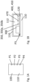
- Figure 1A schematically illustrates a top view onto an embodiment device 100 from the exterior.
- Figure 1B illustrates a schematic sectional view of the device 100 and figure 1C some units and functionalities of the device 100.
- the device 100 is a sensor device.
- the device is configured to be used for an electric system.
- the device 100 can be used to determine, e.g. to continuously monitor, data characteristic for the electric system and/or to acquire electric signals from which the data can be determined.
- the device 100 has a housing 110.
- one or more electrical or electronic components of the device 100 may be arranged and expediently operatively coupled to one another to provide the functionalities of the device 100.
- a conductor carrier 120 (see figure 1B ), e.g. a circuit board, such as a printed circuit board, can couple the components electrically to one another.
- the housing can have or define an interior volume of less than or equal to one of the following: 100 cm 3 , 90 cm 3 , 80 cm 3 , 70 cm 3 , 60 cm 3 , 50 cm 3 , 40 cm 3 , 30 cm 3 . Alternatively or additionally, the interior volume may be greater than or equal to: 5 cm 3 , 10 cm 3 , 15 cm 3 , 20 cm 3 , 25 cm 3 .
- the device 100 can be provided with a particularly small exterior footprint as the interior space required for the electronic functionality is comparatively small. This makes the device easy to use or apply in situations where there is not much space to position the device, e.g. close to conductors of an electric power grid.
- the exterior footprint of the device e.g. the area of the largest exterior surface of the housing 110, may be less than or equal to one of the following: 50 cm 2 , 40 cm 2 , 30 cm 2 .
- the device 100 can be or can be operated as a self-sustainable device or, in other words, a device which does not need (and does not have) a separate energy source to power the device during its operation. Rather, the energy required for the operation of the device 100 may be derived from signals provided to the device for determining a characteristic of the electric system and/or from the electric system itself, e.g. via an inductive coupling. As will be discussed in more detail below, the device 100 expediently comprises an energy harvesting unit to harvest energy from signals characteristic for the state of the electric system and/or the device can draw the power required for its operation directly from the electric system.
- the electric system may be or may comprise a power grid and/or an electric load or electric consumer, e.g. within the power grid.
- the electric system may be a direct current system or an alternating current system.
- the system may be a or may be comprised by a multi-phase alternating current system such as a three-phase alternating current system.
- the frequency with which the alternating current system is operating e.g. the oscillating frequency of the alternating voltage or current, e.g. for each phase
- the device may be provided to determine the characteristic of the electric system at a particular location of the system, e.g. close to the electrical load or close to a location which is characteristic for the power grid, e.g.
- close in this context may mean a location before the first load or consumer is connected to the power input.
- Different electric loads or consumers in a power grid or different locations in a power grid may be provided with different devices 100.
- different electric loads, consumers, phases and/or locations e.g. in different phases or in the same phase
- the device 100 has a plurality of signal inputs or ports P1 ... P4.
- the device has four inputs or ports.
- the respective input or port may be or may comprise a connector, such as a plug-in connector, e.g. a male or female connector.
- the respective input or port may serve as an interface between the device and a signal provider, which can be or is coupled to the device via the respective input or port P1 ... P4.
- the device 100 can receive different signals at different inputs.
- the respective signal can, for instance, be an analog signal.
- the signals may be processed internally in the device 100. Having a plurality of inputs in the device makes the device very versatile.
- the device may be configured to receive different signals or signal types via the respective input or port P1 ... P4.
- the signals of the different types may be processed in the device 100.
- the device is expediently configured to process the signals received via the inputs or ports synchronously.
- the device 100 can be configured to receive any one of, any arbitrarily selected plurality of, or all of the following signals or signal types via one of the inputs or ports, via any arbitrarily selected plurality of the inputs or ports or via all of the inputs or ports P1 ... P4:
- the signals may be provided to the respective input or port P1 ... P4 by a signal provider 200.
- a signal provider is not shown in Figures 1A to 1C (see Figure 2 for an example for such a signal provider 200).
- the signal provider 200 may provide a link to or an interface with the electric system which should be monitored by the device 100.
- the signal provider may be electrically coupled, e.g. wirelessly or wired, to the electrical system, such as to a conductor thereof.
- the coupling may be a wired coupling.
- the coupling may be wireless, e.g. an inductive, coupling.
- the respective signal provider 200 may be, expediently releasably, coupled to the respective input or port P1 ... P4.
- Each input or port may be configured to be coupled with different signal providers. Thus, a large variety of different signals can be fed to the device via the respective inputs or ports. Of course, it is also possible to permanently or irreleasably couple a particular signal provider with the respective input or port.
- the respective signal provider 200 may be a passive electric component.
- the respective input or port P1 ... P4 can be used with any one of, any arbitrarily selected plurality of, or all of the following signal providers:
- the respective signal provider 200 may provide raw signals or non-processed signals, e.g. signals which not yet have been subject to active signal processing steps, such as amplification, differentiation, and/or integration, for example.
- Signal processing e.g. the entire signal processing, may be done in the device 100 after the signals have been received in the inputs or ports P1 ... P4.
- the signals may provide, e.g. continuous, information about the momentary state of the electric system. That is to say, if the device determines or measures the values of the signals at a specific time or instance, these signal values indicate the current or momentary state of the electric system, e.g. the momentary current or momentary voltage at a specific location of the system and/or of a phase of the system.
- the device 100 may enable simultaneously monitoring of four different signals expediently in a synchronous manner. Measurements are or can be expediently taken at a frequency which is between 1 kHz and 7 kHz or between 2 kHz and 6 kHz. This facilitates monitoring of electricity in the electric system.
- FIG. 1C schematically illustrates units of the device and their interrelation.
- the units may be implemented by using electric or electronic components provided in the interior 112 of housing 110.
- the device 100 comprises, for example, any one of any arbitrarily selected plurality of or all of:
- the processing unit 300 may comprise separate inputs or ports for the signals. Thus, the signals may be received in and be processed by the processing unit separately or individually. Further details on the functionalities of the processing unit are set forth further below.
- the energy harvesting unit 400 may render a separate power source (e.g. a battery) pre-loaded with energy in the device 100 superfluous and enables a long-term deployment of the device at the desired location without the need of regular maintenance, e.g. for replacing or recharging a battery.
- a separate power source e.g. a battery
- the switching unit 500 can be operatively coupled to the processing unit 300.
- the processing unit may control the switching unit.
- the switching unit 500 can be implemented as a multi-channel switching unit 500.
- One channel can be associated with and optionally be dedicated to each input or port P1... P4, each channel being switchable between being coupled to either the energy harvesting unit or the processing unit.
- Each channel may be configured to guide or transmit one of the signals S1 ... S4.
- the switching unit 500 may comprise one or more relays, expediently one for each channel or input or port.
- the one or more relays may be controlled and/or switched by the processing unit (e.g. between signal transfer to the processing unit or to the energy harvesting unit), expediently individually for each channel.
- the device comprises one or more internal resistors, e.g. shunt resistors.
- the respective resistor may be positioned in the signal path before the analog-digital converter, e.g. between the switching unit and the processing unit and/or between the analog-digital converter and the switching unit 500.
- the respective resistor may be suitable to convert a current signal into a voltage signal which can be processed further by the analog-digital converter.
- One resistor may be assigned to each input or port P1 ... P4 or each of the signal paths from the inputs or ports to the processing unit 300.
- LoRaWAN has proven to be particularly advantageous.
- the receiving unit may receive software and/or firmware updates for the device 100.
- the energy monitoring unit 470 can be configured to monitor whether
- the processing unit 300 may be configured for any one of, any arbitrarily selected plurality of, or all of the following:
- the data may be calculated for each phase of the system.
- the momentary current and/or voltage frequencies may vary in the electric system, i.e. the frequency may deviate from the nominal characteristic frequency the system should employ, e.g. 50 Hz or 60 Hz.
- the device 100 can be configured to determine the associated momentary frequency or data indicative thereof.
- the data may be calculated using RMS-averaging (RMS: Root Mean Square) over a time interval.
- the frequencies may be calculated or determined by analyzing the time characteristics of the voltage or current in the time interval.
- the respective frequency may be determined from the time characteristic, e.g. from periodic patterns in the time characteristics of the respective signal, e.g. using the Goertzel algorithm.
- the time interval is expediently chosen so as to cover at least 40 oscillation cycles of the voltage or current in an alternating current system, e.g. one phase of a multi-phase alternating current system.
- the time interval may be 1s for example.
- the calculation operation frequency may be less than 10 Hz, e.g. 1Hz.
- the frequency with which calculation operations are performed may be less than the frequency of the determining operations.
- the device can be configured to perform simulation operations or a simulation operation is not performed, e.g. depending on how the device 100 should be used. This increases the versatility of the device.
- Using a combination of measured (signal) values and simulated values to determine, e.g. calculate, characteristics of the electric system (e.g. at a specific time) can simplify the handling of the device, e.g. as some voltages do not have to be determined (which may avoid a wired connection to a conductor which always entails a risk) but can be simulated.
- information which usually is derivable only from a measured signal e.g. harmonics in the voltage or the current in a different conductor than the one from which the signals were determined or measured, is not accessible via the simulated values.
- the device may use only measured signal values, e.g. for a particular portion of the system, such as one phase, or a combination of measured and simulated values or only simulated values, e.g. for another portion of the system, such as for another phase.
- the data may include any one of the data mentioned above (potentially without the frequencies or with the frequencies).
- the processing unit renders an integrator in hardware which usually has to be provided for a Rogowski coil superfluous.
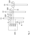
- Figure 2 illustrates the device 100 as described previously used in a multi-phase alternating current system.
- the system is a three-phase alternating current system.
- Each phase has a dedicated conductor.
- the electric system may be a typical three-phase electric power system with three lines or conductors, each carrying alternating currents and voltages (the phases being usually offset by a phase angle of 120°).
- Figure 2 shows the three phase conductors or lines C1 for the first phase, C2 for the second phase, and C3 for the third phase. Further, figure 2 shows the associated neutral line or conductor N.
- the three phases have the same nominal characteristic frequency or oscillation frequency, e.g. 50 Hz or 60 Hz and/or approximately the same amplitudes in voltage.
- a signal provider 200 is assigned to each of the conductors C1 to C3.
- the respective signal provider may be of the following type: a Rogowski coil, a current transformer or a provider employing a shunt resistor.
- the types of signal provider used for the respective conductor may be identical or different.
- the signal provider 200 may provide signals I1 to I3, e.g. signals indicative of the momentary or instantaneous current in the associated conductor.
- the signals I1 to I3 may be fed to the device 100 via inputs or ports P1 to P3 (e.g. one signal per port).
- Signal I1 is received by the device via P1
- the signal I2 is received by the device via P2
- the signal I3 is received by the device via P3.
- Signals I1 to I3 may be voltage signals (e.g.
- the input or port P4 can be used to receive a voltage signal U1 indicative of a phase voltage in C1 (i.e. of the voltage between C1 and N).
- the voltage signal U1 may be obtained via a voltage divider, for example.
- the voltage U1 i.e. the alternating voltage of the first phase
- the switching unit 500 and/or the processing unit 300 can be operable to selectively draw power from the voltage providing the voltage signal (U1 in this embodiment), e.g.
- the harvested energy from other signals is not sufficient for operating the device.
- energy harvested by the device from the signals I1 to I3 may not be absolutely necessary to operate the device 100 (although the device may be operable with harvested energy only).
- energy may be harvested and stored in the device 100, e.g. to provide an energy backup supply in case there is no longer power supplied or suppliable directly via U1.
- the device may use the energy stored in the energy storage to send a message indicating the potential energy shortage to a receiver, e.g. to a gateway, and/or use the energy stored in the device to temporarily provide energy for the operation of the device.
- signals can be fed to the device and be processed therein which are not particularly suitable for energy harvesting.
- Current signals e.g. provided via a current transformer
- voltage signals e.g. provided via a Rogowski coil
- the device 100 can monitor the currents in C1 to C3 via the signals I1 to I3, where the momentary values of the current can be determined or measured by the processing unit 300, e.g. with a frequency of 4kHz, based on the signals provided by the signal providers 200 (if Rogowski coils are used, the processing unit may process the signal to provide the current signal indicative of the current to provide the current signal of interest).
- the momentary current can be monitored by the device for each of the three phases. Via the signal U1, the momentary voltage in the conductor C1 can be determined.
- the determining frequency may be identical for all signals reaching the processing unit from different ports at a specific time.
- the determining frequency may be lowered or raised by the processing unit, e.g. to reduce energy consumption or to shorten or lengthen the time interval with which signal values are measured or determined.
- the time-voltage characteristic of the voltage U1 (i.e. how the voltage U1 at conductor C1 changes with time) can be determined via the measured voltage signal values.
- the time-voltage characteristic of the voltages U2 and U3 (in each case relative to the neutral line N) of the other phases can be simulated.
- U2 can be simulated by adding a time offset corresponding to a phase offset, e.g. of 120°, to the time-voltage characteristic for U1 (which shifts the time-voltage characteristic of U1 by a time offset corresponding to the phase offset) in order to provide the time-voltage characteristic for U2 (and thereby the value at the specific time).
- U3 can be simulated by adding a time offset corresponding to a phase offset (different to the one for U2), e.g. 240°, to the time-voltage characteristic for U1 (which shifts the time-voltage characteristic of U1 by a time offset corresponding to the phase offset) in order to provide the time-voltage characteristic for U3 (and thereby the value at the specific time).
- the respective simulation is expediently performed by firmware or software stored in the device, e.g. in the processing unit and/or in the program memory.
- the time offset corresponding to the phase offset added to U1 may be constant, e.g. one constant offset for simulating U2 and another constant offset for simulating U3.
- the time offset may be 120° at the nominal characteristic frequency of e.g. 50 Hz or 60Hz (one oscillation cycle at the nominal characteristic frequency corresponding to 360°) for U2 (assuming that U2 is the second phase successive to U1) and 240° at the nominal characteristic frequency for U3 (which is the third phase which is successive to U2).
- the phase offset of 120° is the usual phase angle offset between two different successive phases in a three-phase alternating current system.
- the simulated time-voltage characteristic may have the same momentary values as the time-voltage characteristic determined from the measured (signal) values albeit phase-shifted.
- the higher harmonics may be identical (albeit shifted).
- This simulation may already be sufficient to provide simulated signal values (e.g. voltage values) to calculate data (together with the measured values of U1, I1, I2 and/or I3) which characterizes the three-phase alternating current system well, e.g. each phase of the system.
- the data which is calculated can be the data described above.
- the data may be transmitted in data sets, e.g. in bundles of data sets (where each data set may comprise data characterizing the electric system and (optionally) time information indicating the time at or for which the data in the data set was determined).
- the current and/or voltage frequency in a power grid may vary, e.g. depending on the load in the grid.
- the momentary frequency may be lower, e.g. 49.5 Hz, or higher, e.g. 50.5 Hz, than the nominal (characteristic) frequency.
- the time offset for the simulation may be dynamically determined, e.g. based on the momentary characteristic frequency.
- the momentary characteristic frequency can be determined based on measured or determined signal values (e.g. the current signal values or voltage signal values), e.g. based on the voltage signal values of U1.
- the processing unit may take a representative portion of the time-voltage characteristic of the first voltage U1 as the time-voltage characteristic which is used to determine the momentary characteristic frequency.
- the determined frequency may be used to determine the time offset from the phase offset.
- the time-voltage characteristic used for the frequency determination may be formed by the first voltage signal values determined directly before the offset is determined.
- the representative portion may have a length of one oscillation cycle or more than one cycle.
- the momentary frequency can be determined from that portion, e.g. by averaging if more than one cycle is used. If the momentary frequency, e.g. the voltage frequency determined from the time-voltage characteristic of U1 (i.e.
- the time offset for shifting the time-voltage characteristic of U1 to simulate or provide the time-voltage characteristic of U2 or U3 may be increased by an amount determined by the deviation of the momentary frequency from the nominal frequency. If the momentary frequency is higher than the nominal frequency the time offset may be reduced by an amount determined by the deviation of the momentary frequency from the nominal frequency.
- the determined momentary frequency may be assumed to be identical for all phases.
- the momentary characteristic frequency may be derived, e.g. calculated, from a known time-voltage characteristic (e.g. based on values stored in the device from previous measurements or determining operations).
- the momentary characteristic frequency may be calculated using a Fourier transform, e.g. a discrete Fourier transform (DFT).
- DFT discrete Fourier transform
- the momentary characteristic frequency may be determined by an algorithm, e.g. by the Goertzel algorithm.
- This algorithm is particularly efficient with respect to energy consumption.
- the algorithm may be implemented in firmware or software.
- the algorithm can preferably be performed by the processing unit.
- the Goertzel algorithm is a method for frequency analysis of digital signals. It is an efficient method for calculating individual components of a Discrete Fourier Transform (DFT), which is particularly useful when only a small portion of the spectrum is required. If one wants to achieve precise frequency determination, e.g. in the 1/10 Hz range, with few measurement points, the Goertzel algorithm offers several remarkable advantages, e.g.:
- the Goertzel algorithm is an efficient, accurate, and flexible frequency analysis tool that is ideally suited for applications with limited measurement points and high frequency resolution requirements.
- Simulating the time-voltage characteristic (or the associated voltage signal values) of one or more phases based on the measured time-voltage characteristic (or measured voltage signal values) of another phase, e.g. as in the solution described above in connection with figure 2 is advantageous.
- the user of the device e.g. an electrician
- Putting the device to use is easy and less risky as contact connection does not have to be made to the voltages which are simulated, e.g. a standard wall outlet may be sufficient to provide the time-voltage characteristic of U1.
- the processing unit 300 may be configured to derive, e.g. calculate, the corresponding current signal value based on the voltage signal value, e.g. by adding a time corresponding to a 90° phase shift (at the nominal characteristic frequency or the momentary frequency) to the associated time-voltage characteristic or by integrating the time-voltage characteristic in the processing unit.
- a separate integrator is not needed in the proposed setting.
- figure 2 merely gives one example of how the proposed device 100 can be put to use.
- Other uses are possible, such as, for example, providing signals indicative of the current at three different locations of a selected phase, e.g. one of the three phases, to inputs or ports P1 to P3 along with the associated phase voltage to the remaining input or port P4.
- a simulation operation may not be needed.
- the device may nevertheless be configured to be able to perform a simulation operation (if it were used in a setting where the simulation might be beneficial).
- the device 100 can be easily placed at different locations in an electric system, such as a power grid and generate data characteristic for the system at this location.
- the data can be transmitted to and collected by a further electronic device, e.g. by a computing device or server.
- the device 100 may be a portable and/or mobile device which is installed or mounted close to that location in the electric system which should be monitored with the device.
- the device may be configured such that the power consumption, e.g. the average power consumption, is less than 0.25 mW and/or greater than 0.1 mW per input or port of the device.
- the total average power consumption of the device during its operation may be less than 1 mW (e.g. if the device 100 with four inputs operates as described further above, particularly with a frequency of transmission events of less than or equal to one transmission event per minute) and/or greater than 0.3 mW.
- the device is expediently configured such that the determining operation, the simulation operation, and/or the calculation operation is carried out to provide signal values and/or data characteristic for the system at different times to enable a time-resolved monitoring of the multi-phase alternating current system.
- Each phase of the system may be monitored, e.g. only one phase or more than one phase.
- the frequency with which the respective operations are performed may be equal or different. Transmission events may be performed at a lower frequency than calculation operations. Simulation operations may be performed at the same frequency as the determining operation or as the calculation operation.
- not all of the inputs or ports have to be provided with signals for the device to work (e.g. only one input or port can be provided with a signal or only two inputs or ports or only three inputs or ports) but all inputs or ports can be provided with signals of course.
Landscapes
- Physics & Mathematics (AREA)
- General Physics & Mathematics (AREA)
- Engineering & Computer Science (AREA)
- Power Engineering (AREA)
- Remote Monitoring And Control Of Power-Distribution Networks (AREA)
Claims (14)
- Vorrichtung (100) für ein elektrisches System, wobei die Vorrichtung Folgendes umfasst:eine Mehrzahl von Signaleingängen (P1, P2, P3, P4), wobei jeder Signaleingang aus der Mehrzahl von Signaleingängen konfiguriert ist, um ein Signal zu empfangen, das mit dem elektrischen System assoziiert ist und den momentanen Zustand des elektrischen Systems zu einer spezifischen Zeit angibt, undeine Verarbeitungseinheit (300), wobei die Verarbeitungseinheit konfiguriert ist, um einen Bestimmungsvorgang durchzuführen, wobeiin dem Bestimmungsvorgang ein Signalwert des an einem der, mehreren der oder allen der Signaleingänge empfangenen Signals bestimmt, z. B. gemessen wird, wobei der bestimmte Signalwert den momentanen Zustand des elektrischen Systems zu der spezifischen Zeit angibt, wobeidas elektrische System ein mehrphasiges Wechselstromsystem ist, und wobei die Verarbeitungseinheit konfiguriert ist, um einen Simulationsvorgang durchzuführen, der den Signalwert verwendet, der durch die Verarbeitungseinheit bestimmt wird, wobei der Signalwert den momentanen Zustand einer Phase des mehrphasigen Wechselstromsystems zu der spezifischen Zeit angibt, und wobei der Signalwert verwendet wird, um einen Signalwert zu simulieren, der den momentanen Zustand einer anderen Phase des mehrphasigen Wechselstromsystems zu der spezifischen Zeit angibt, wobeidie Vorrichtung eine Energiegewinnungseinheit (400) umfasst, die konfiguriert ist, um elektrische Energie zu gewinnen, wobeidie Vorrichtung eine Schalteinheit (500) umfasst, wobei die Schalteinheit betriebsfähig ist, Übertragung von Signalen, die durch die Vorrichtung über die Mehrzahl von Eingängen empfangen werden, zwischen der Verarbeitungseinheit und der Energiegewinnungseinheit oder einer Kombination aus beiden zu schalten, wobeidie Schalteinheit konfiguriert ist, sodass Signale, die über jeden Eingang empfangen werden, unabhängig zwischen der Verarbeitungseinheit und der Energiegewinnungseinheit oder einer Kombination aus beiden geschaltet werden können, und wobeidie Vorrichtung eine Energiespeichereinheit (450) aufweist, die konfiguriert ist, um gewonnene Energie zu speichern.
- Vorrichtung nach Anspruch 1, wobei die Vorrichtung Folgendes umfasst:einen ersten Signaleingang aus der Mehrzahl von Signaleingängen, wobei der erste Signaleingang konfiguriert ist, um ein erstes Signal zu empfangen, das einen momentanen ersten Strom einer ersten Phase eines mehrphasigen Wechselstroms in einem ersten Leiter angibt,einen zweiten Signaleingang aus der Mehrzahl von Signaleingängen, wobei der zweite Signaleingang konfiguriert ist, um ein zweites Signal zu empfangen, das einen momentanen zweiten Strom einer zweiten Phase des mehrphasigen Wechselstroms in einem zweiten Leiter angibt,einen Spannungssignaleingang aus der Mehrzahl von Signaleingängen, wobei der Spannungssignaleingang konfiguriert ist, um ein Spannungssignal zu empfangen, das eine momentane erste Spannung der ersten Phase des mehrphasigen Wechselstroms an dem ersten Leiter angibt, wobeiin dem Bestimmungsvorgangein erster Spannungssignalwert bestimmt, z. B. gemessen wird, wobei der erste Spannungssignalwert das Spannungssignal zu der spezifischen Zeit angibt, und wobeidie Verarbeitungseinheit konfiguriert ist, umeinen Simulationsvorgang durchzuführen, wobei in dem Simulationsvorgang ein zweiter Spannungssignalwert simuliert wird, wobei der zweite Spannungssignalwert eine momentane zweite Spannung der zweiten Phase des mehrphasigen Wechselstroms zu der spezifischen Zeit an dem zweiten Leiter angibt, wobei der zweite Spannungssignalwert basierend auf dem ersten Spannungssignalwert zu der spezifischen Zeit simuliert wird.
- Vorrichtung nach Anspruch 2, wobei die Vorrichtung ferner einen dritten Signaleingang aus der Mehrzahl von Signaleingängen umfasst, wobei der dritte Signaleingang konfiguriert ist, um ein drittes Signal zu empfangen, das einen momentanen dritten Strom einer dritten Phase eines mehrphasigen Wechselstroms in einem dritten Leiter angibt, wobei
in dem Simulationsvorgang ein dritter Spannungssignalwert simuliert wird, wobei der dritte Spannungssignalwert eine momentane dritte Spannung der dritten Phase des mehrphasigen Wechselstroms zu der spezifischen Zeit an dem dritten Leiter angibt, wobei der dritte Spannungswert basierend auf dem ersten Spannungswert zu der spezifischen Zeit simuliert wird. - Vorrichtung nach Anspruch 2 oder 3, wobei das Simulieren des zweiten Spannungssignalwertes eine Verwendung einer Zeit-Spannungs-Charakteristik der ersten Spannung und eine Verschiebung der Zeit-Spannungs-Charakteristik um einen Versatz umfasst.
- Vorrichtung nach Anspruch 3 und 4, wobei das Simulieren des dritten Spannungssignalwertes die Verwendung der Zeit-Spannungs-Charakteristik der ersten Spannung und die Verschiebung der Zeit-Spannungs-Charakteristik um einen anderen Versatz umfasst.
- Vorrichtung nach Anspruch 4 oder 5, wobei die Zeit-Spannungs-Charakteristik der ersten Spannung auf einer Mehrzahl von ersten Spannungssignalwerten basiert, die zuvor durch die Verarbeitungseinheit bestimmt wurden.
- Vorrichtung nach einem der vorhergehenden Ansprüche 4 bis 6, wobei der Versatz durch den Phasenversatz zwischen der ersten Phase und der zweiten Phase des mehrphasigen Wechselstroms bestimmt wird und/oder wobei der andere Versatz durch den Phasenversatz zwischen der ersten Phase und der dritten Phase des mehrphasigen Wechselstroms bestimmt wird, und/oder
wobei die Vorrichtung konfiguriert ist, um den Versatz oder den anderen Versatz basierend auf der Zeit-Spannungs-Charakteristik der ersten Spannung und/oder basierend auf einer ersten Spannungsfrequenz-Charakteristik für die erste Spannung dynamisch zu bestimmen. - Vorrichtung nach einem der vorhergehenden Ansprüche, wobei die Vorrichtung konfiguriert ist, um den Bestimmungsvorgang mit einer Bestimmungsfrequenz durchzuführen, und wobei die Bestimmungsfrequenz zwischen 1 kHz und 7 kHz oder zwischen 2 kHz und 6 kHz ist.
- Vorrichtung nach einem der vorhergehenden Ansprüche, wobei die Mehrzahl von Signaleingängen, z. B. der erste Signaleingang, der zweite Signaleingang und/oder der dritte Signaleingang, konfiguriert ist, um Signale von Signalbereitstellern (200) zu empfangen, die an die Eingänge aus der Mehrzahl von Eingängen koppelbar oder gekoppelt sind, wobei das Signal, das durch den jeweiligen Signalbereitsteller an den assoziierten Eingang bereitgestellt wird, eines der Folgenden ist:- Spannungssignale, die einen Strom angeben,- Spannungssignale, die eine Spannung angeben,- Stromsignale, die einen Strom angeben,- analoge Signale,- Gleichstrom-Signale,- Wechselstrom-Signale, undwobei der jeweilige Signalbereitsteller eines von Folgendem ist oder umfasst:- ein Stromwandler,- eine Rogowski-Spule,- ein Nebenschlusswiderstand.
- Vorrichtung nach einem der vorhergehenden Ansprüche, wobei die Verarbeitungseinheit konfiguriert ist, um einen Berechnungsvorgang durchzuführen, wobei, in dem Berechnungsvorgang, Daten berechnet werden, die für das elektrische System charakteristisch sind, , wobei die Daten, die für das mehrphasige Wechselstromsystem charakteristisch sind, z. B. zu der spezifischen Zeit, Folgendes umfassen:a) Daten, die nur basierend auf einem oder mehreren Signalwerten berechnet werden, die in dem Bestimmungsvorgang bestimmt werden, und/oderb) Daten, die basierend auf einem oder mehreren Signalwerten, die in dem Bestimmungsvorgang bestimmt werden, und einem oder mehreren Signalwerten, die in dem Simulationsvorgang simuliert werden, berechnet werden, und wobei optionaldie Daten, die für das mehrphasige Wechselstromsystem charakteristisch sind, ein beliebiges von, eine beliebige willkürlich ausgewählte Mehrzahl von oder alles von Folgendem umfassen:- aktive Last,- aktive Energie,- reaktive Last,- reaktive Energie,- Scheinlast,- Scheinenergie,- Leistungsfaktor,- Spannungsfrequenz,- Stromfrequenz.
- Vorrichtung nach einem der vorhergehenden Ansprüche, wobei die Vorrichtung ein Vorrichtungsgehäuse (110) aufweist, wobei das Vorrichtungsgehäuse das Äußere der Vorrichtung definiert, wobei das Vorrichtungsgehäuse einen Innenraum (112) aufweist, wobei ein Volumen des Innenraumes kleiner als oder gleich 100 cm3 und/oder größer als oder gleich 10 cm3 ist.
- Vorrichtung nach einem der vorhergehenden Ansprüche, wobei die Vorrichtung einen durchschnittlichen Leistungsverbrauch von kleiner als oder gleich 1 mW aufweist.
- Vorrichtung nach einem der vorhergehenden Ansprüche, wobei die Vorrichtung eine drahtlose Übertragungseinheit (600) umfasst, wobei die drahtlose Übertragungseinheit betriebsfähig ist, um Daten zu übertragen, die für das elektrische System charakteristisch sind, z. B. zu einem Gateway.
- Vorrichtung nach einem der vorhergehenden Ansprüche, wobei die Vorrichtung eine Energieüberwachungseinheit (470) aufweist,wobei die Energieüberwachungseinheit konfiguriert ist, um zu überwachen, obi) ausreichend Energie über die Energiegewinnungseinheit bereitgestellt wird, und/oderii) ausreichend Energie in der Energiespeichereinheit gespeichert ist,um Betrieb der Vorrichtung, z. B. der Verarbeitungseinheit und/oder der Übertragungseinheit, fortzusetzen, und wobei, wenn die Energieüberwachungseinheit erfasst, dass unzureichend Energie bereitgestellt und/oder gespeichert ist, die Vorrichtung konfiguriert ist, um ihren Betrieb anzupassen, um Energieverbrauch zu reduzieren, z. B. durch Senken der Bestimmungsfrequenz oder einer Frequenz von Datenübertragungsereignissen, und/oder um eine Nachricht zu übertragen, die den Mangel oder den potentiellen Mangel an Energie signalisiert.
Priority Applications (1)
| Application Number | Priority Date | Filing Date | Title |
|---|---|---|---|
| EP23174590.2A EP4467993B1 (de) | 2023-05-22 | 2023-05-22 | Vorrichtung für elektrische systeme |
Applications Claiming Priority (1)
| Application Number | Priority Date | Filing Date | Title |
|---|---|---|---|
| EP23174590.2A EP4467993B1 (de) | 2023-05-22 | 2023-05-22 | Vorrichtung für elektrische systeme |
Publications (3)
| Publication Number | Publication Date |
|---|---|
| EP4467993A1 EP4467993A1 (de) | 2024-11-27 |
| EP4467993C0 EP4467993C0 (de) | 2025-06-25 |
| EP4467993B1 true EP4467993B1 (de) | 2025-06-25 |
Family
ID=86498006
Family Applications (1)
| Application Number | Title | Priority Date | Filing Date |
|---|---|---|---|
| EP23174590.2A Active EP4467993B1 (de) | 2023-05-22 | 2023-05-22 | Vorrichtung für elektrische systeme |
Country Status (1)
| Country | Link |
|---|---|
| EP (1) | EP4467993B1 (de) |
Family Cites Families (8)
| Publication number | Priority date | Publication date | Assignee | Title |
|---|---|---|---|---|
| US8140283B2 (en) * | 2008-12-24 | 2012-03-20 | Schweitzer Engineering Laboratories, Inc. | Independent frequency measurement and tracking |
| US8680842B2 (en) * | 2010-10-01 | 2014-03-25 | Schneider Electric USA, Inc. | Method for measurement of total harmonic distortion |
| FR2998061A1 (fr) * | 2012-11-12 | 2014-05-16 | Schneider Electric Ind Sas | Dispositif et procede de determination de la tension et de la puissance de chaque phase dans un reseau moyenne tension |
| FR3026489B1 (fr) * | 2014-09-29 | 2016-12-09 | Schneider Electric Ind Sas | Procede d'estimation d'une tension et dispositif permettant une telle estimation |
| US11605974B2 (en) * | 2019-01-31 | 2023-03-14 | Abb Schweiz Ag | On-line power measurement |
| US20210109136A1 (en) * | 2019-10-11 | 2021-04-15 | Schweitzer Engineering Laboratories, Inc. | Methods to automatically associate wireless current sensors with voltages of a power system |
| US11268995B2 (en) * | 2019-10-11 | 2022-03-08 | Schweitzer Engineering Laboratories, Inc. | Intelligent electronic device control using wirelessly transmitted multi-phase electrical measurements |
| US11381084B1 (en) * | 2021-10-05 | 2022-07-05 | Schweitzer Engineering Laboratories, Inc. | Frequency measurement for load shedding and accurate magnitude calculation |
-
2023
- 2023-05-22 EP EP23174590.2A patent/EP4467993B1/de active Active
Also Published As
| Publication number | Publication date |
|---|---|
| EP4467993C0 (de) | 2025-06-25 |
| EP4467993A1 (de) | 2024-11-27 |
Similar Documents
| Publication | Publication Date | Title |
|---|---|---|
| US8626462B2 (en) | Phase identification system and method | |
| US9335352B2 (en) | Branch circuit monitor power measurement | |
| CN101833051B (zh) | 氧化锌避雷器带电测试仪 | |
| US6185508B1 (en) | Power meter for determining parameters of multi-phase power lines | |
| US8810233B2 (en) | Phase identification system and method | |
| Music et al. | Integrated power quality monitoring system and the benefits of integrating smart meters | |
| US9423434B2 (en) | Method and system for measuring electrical quantity in electrical network | |
| CN101493479B (zh) | 虚拟电流生成电路及方法、电能表校验仪 | |
| EP4467993B1 (de) | Vorrichtung für elektrische systeme | |
| CN216144942U (zh) | 无线电气传感器、电参量测量计算装置及系统 | |
| US20240310417A1 (en) | Wireless electrical sensor and electrical parameter measurement and calculation apparatus, method and system | |
| CN202631654U (zh) | 双通道准同步综合电能检测网 | |
| CN115078803A (zh) | 一种分布式无线电参量采样系统及方法 | |
| CN112865300A (zh) | 一种基于ZigBee的电能质量监控系统及方法 | |
| CN105699740A (zh) | 一种测量全量程范围电流的方法 | |
| CN207039201U (zh) | 一种三相电源系统 | |
| KR101120076B1 (ko) | 무정전 병렬형 전력측정 장치를 이용한 일괄 전력측정 시스템 | |
| RU2799705C1 (ru) | Комплекс мониторинга и управления электрическими нагрузками с контролем фазных токов и тока в нулевом проводнике | |
| RU2624001C1 (ru) | Интеллектуальная микропроцессорная система для определения величины технических потерь электроэнергии | |
| RU2786764C1 (ru) | Комплекс мониторинга и управления электрическими нагрузками | |
| US20230288460A1 (en) | Apparatus and method for measuring active electric power in an electric circuit | |
| RU2748936C1 (ru) | Прибор контроля потребления электрической энергии в сети низкого напряжения | |
| Billas et al. | Low-cost Power Analyser Design & Implementation | |
| CN107394800A (zh) | 一种三相电源系统 | |
| CN109975612A (zh) | 一种简易自动电阻测试装置 |
Legal Events
| Date | Code | Title | Description |
|---|---|---|---|
| PUAI | Public reference made under article 153(3) epc to a published international application that has entered the european phase |
Free format text: ORIGINAL CODE: 0009012 |
|
| STAA | Information on the status of an ep patent application or granted ep patent |
Free format text: STATUS: REQUEST FOR EXAMINATION WAS MADE |
|
| 17P | Request for examination filed |
Effective date: 20240808 |
|
| AK | Designated contracting states |
Kind code of ref document: A1 Designated state(s): AL AT BE BG CH CY CZ DE DK EE ES FI FR GB GR HR HU IE IS IT LI LT LU LV MC ME MK MT NL NO PL PT RO RS SE SI SK SM TR |
|
| GRAP | Despatch of communication of intention to grant a patent |
Free format text: ORIGINAL CODE: EPIDOSNIGR1 |
|
| STAA | Information on the status of an ep patent application or granted ep patent |
Free format text: STATUS: GRANT OF PATENT IS INTENDED |
|
| RIC1 | Information provided on ipc code assigned before grant |
Ipc: G01R 15/18 20060101ALN20241125BHEP Ipc: G01R 19/25 20060101AFI20241125BHEP |
|
| RIC1 | Information provided on ipc code assigned before grant |
Ipc: G01R 15/18 20060101ALN20241204BHEP Ipc: G01R 19/25 20060101AFI20241204BHEP |
|
| INTG | Intention to grant announced |
Effective date: 20241216 |
|
| GRAS | Grant fee paid |
Free format text: ORIGINAL CODE: EPIDOSNIGR3 |
|
| RIN1 | Information on inventor provided before grant (corrected) |
Inventor name: FRIEDRICH, RICK Inventor name: RIEGEL, GEORG |
|
| GRAA | (expected) grant |
Free format text: ORIGINAL CODE: 0009210 |
|
| STAA | Information on the status of an ep patent application or granted ep patent |
Free format text: STATUS: THE PATENT HAS BEEN GRANTED |
|
| AK | Designated contracting states |
Kind code of ref document: B1 Designated state(s): AL AT BE BG CH CY CZ DE DK EE ES FI FR GB GR HR HU IE IS IT LI LT LU LV MC ME MK MT NL NO PL PT RO RS SE SI SK SM TR |
|
| REG | Reference to a national code |
Ref country code: GB Ref legal event code: FG4D |
|
| REG | Reference to a national code |
Ref country code: CH Ref legal event code: EP |
|
| REG | Reference to a national code |
Ref country code: CH Ref legal event code: EP |
|
| REG | Reference to a national code |
Ref country code: IE Ref legal event code: FG4D |
|
| REG | Reference to a national code |
Ref country code: DE Ref legal event code: R096 Ref document number: 602023004221 Country of ref document: DE |
|
| U01 | Request for unitary effect filed |
Effective date: 20250718 |
|
| U07 | Unitary effect registered |
Designated state(s): AT BE BG DE DK EE FI FR IT LT LU LV MT NL PT RO SE SI Effective date: 20250725 |
|
| PG25 | Lapsed in a contracting state [announced via postgrant information from national office to epo] |
Ref country code: GR Free format text: LAPSE BECAUSE OF FAILURE TO SUBMIT A TRANSLATION OF THE DESCRIPTION OR TO PAY THE FEE WITHIN THE PRESCRIBED TIME-LIMIT Effective date: 20250926 Ref country code: NO Free format text: LAPSE BECAUSE OF FAILURE TO SUBMIT A TRANSLATION OF THE DESCRIPTION OR TO PAY THE FEE WITHIN THE PRESCRIBED TIME-LIMIT Effective date: 20250925 |
|
| PG25 | Lapsed in a contracting state [announced via postgrant information from national office to epo] |
Ref country code: HR Free format text: LAPSE BECAUSE OF FAILURE TO SUBMIT A TRANSLATION OF THE DESCRIPTION OR TO PAY THE FEE WITHIN THE PRESCRIBED TIME-LIMIT Effective date: 20250625 |
|
| PG25 | Lapsed in a contracting state [announced via postgrant information from national office to epo] |
Ref country code: RS Free format text: LAPSE BECAUSE OF FAILURE TO SUBMIT A TRANSLATION OF THE DESCRIPTION OR TO PAY THE FEE WITHIN THE PRESCRIBED TIME-LIMIT Effective date: 20250925 |
|
| PG25 | Lapsed in a contracting state [announced via postgrant information from national office to epo] |
Ref country code: IS Free format text: LAPSE BECAUSE OF FAILURE TO SUBMIT A TRANSLATION OF THE DESCRIPTION OR TO PAY THE FEE WITHIN THE PRESCRIBED TIME-LIMIT Effective date: 20251025 |
|
| PG25 | Lapsed in a contracting state [announced via postgrant information from national office to epo] |
Ref country code: SM Free format text: LAPSE BECAUSE OF FAILURE TO SUBMIT A TRANSLATION OF THE DESCRIPTION OR TO PAY THE FEE WITHIN THE PRESCRIBED TIME-LIMIT Effective date: 20250625 |
|
| PG25 | Lapsed in a contracting state [announced via postgrant information from national office to epo] |
Ref country code: CZ Free format text: LAPSE BECAUSE OF FAILURE TO SUBMIT A TRANSLATION OF THE DESCRIPTION OR TO PAY THE FEE WITHIN THE PRESCRIBED TIME-LIMIT Effective date: 20250625 |
|
| PG25 | Lapsed in a contracting state [announced via postgrant information from national office to epo] |
Ref country code: PL Free format text: LAPSE BECAUSE OF FAILURE TO SUBMIT A TRANSLATION OF THE DESCRIPTION OR TO PAY THE FEE WITHIN THE PRESCRIBED TIME-LIMIT Effective date: 20250625 |
|
| PG25 | Lapsed in a contracting state [announced via postgrant information from national office to epo] |
Ref country code: SK Free format text: LAPSE BECAUSE OF FAILURE TO SUBMIT A TRANSLATION OF THE DESCRIPTION OR TO PAY THE FEE WITHIN THE PRESCRIBED TIME-LIMIT Effective date: 20250625 |
|
| PG25 | Lapsed in a contracting state [announced via postgrant information from national office to epo] |
Ref country code: ES Free format text: LAPSE BECAUSE OF FAILURE TO SUBMIT A TRANSLATION OF THE DESCRIPTION OR TO PAY THE FEE WITHIN THE PRESCRIBED TIME-LIMIT Effective date: 20250625 |
|
| U20 | Renewal fee for the european patent with unitary effect paid |
Year of fee payment: 4 Effective date: 20260302 |
|
| PLBE | No opposition filed within time limit |
Free format text: ORIGINAL CODE: 0009261 |
|
| STAA | Information on the status of an ep patent application or granted ep patent |
Free format text: STATUS: NO OPPOSITION FILED WITHIN TIME LIMIT |