EP4467934A1 - A sensor housing for a sensor module - Google Patents
A sensor housing for a sensor module Download PDFInfo
- Publication number
- EP4467934A1 EP4467934A1 EP23174931.8A EP23174931A EP4467934A1 EP 4467934 A1 EP4467934 A1 EP 4467934A1 EP 23174931 A EP23174931 A EP 23174931A EP 4467934 A1 EP4467934 A1 EP 4467934A1
- Authority
- EP
- European Patent Office
- Prior art keywords
- temperature
- sensor module
- sensor
- camera
- module
- Prior art date
- Legal status (The legal status is an assumption and is not a legal conclusion. Google has not performed a legal analysis and makes no representation as to the accuracy of the status listed.)
- Pending
Links
Images

Classifications
-
- G—PHYSICS
- G01—MEASURING; TESTING
- G01N—INVESTIGATING OR ANALYSING MATERIALS BY DETERMINING THEIR CHEMICAL OR PHYSICAL PROPERTIES
- G01N21/00—Investigating or analysing materials by the use of optical means, i.e. using sub-millimetre waves, infrared, visible or ultraviolet light
- G01N21/84—Systems specially adapted for particular applications
- G01N21/88—Investigating the presence of flaws or contamination
- G01N21/8851—Scan or image signal processing specially adapted therefor, e.g. for scan signal adjustment, for detecting different kinds of defects, for compensating for structures, markings, edges
-
- H—ELECTRICITY
- H04—ELECTRIC COMMUNICATION TECHNIQUE
- H04N—PICTORIAL COMMUNICATION, e.g. TELEVISION
- H04N23/00—Cameras or camera modules comprising electronic image sensors; Control thereof
- H04N23/50—Constructional details
- H04N23/52—Elements optimising image sensor operation, e.g. for electromagnetic interference [EMI] protection or temperature control by heat transfer or cooling elements
-
- G—PHYSICS
- G01—MEASURING; TESTING
- G01J—MEASUREMENT OF INTENSITY, VELOCITY, SPECTRAL CONTENT, POLARISATION, PHASE OR PULSE CHARACTERISTICS OF INFRARED, VISIBLE OR ULTRAVIOLET LIGHT; COLORIMETRY; RADIATION PYROMETRY
- G01J5/00—Radiation pyrometry, e.g. infrared or optical thermometry
- G01J5/02—Constructional details
- G01J5/06—Arrangements for eliminating effects of disturbing radiation; Arrangements for compensating changes in sensitivity
- G01J5/061—Arrangements for eliminating effects of disturbing radiation; Arrangements for compensating changes in sensitivity by controlling the temperature of the apparatus or parts thereof, e.g. using cooling means or thermostats
-
- G—PHYSICS
- G03—PHOTOGRAPHY; CINEMATOGRAPHY; ANALOGOUS TECHNIQUES USING WAVES OTHER THAN OPTICAL WAVES; ELECTROGRAPHY; HOLOGRAPHY
- G03B—APPARATUS OR ARRANGEMENTS FOR TAKING PHOTOGRAPHS OR FOR PROJECTING OR VIEWING THEM; APPARATUS OR ARRANGEMENTS EMPLOYING ANALOGOUS TECHNIQUES USING WAVES OTHER THAN OPTICAL WAVES; ACCESSORIES THEREFOR
- G03B17/00—Details of cameras or camera bodies; Accessories therefor
- G03B17/55—Details of cameras or camera bodies; Accessories therefor with provision for heating or cooling, e.g. in aircraft
-
- H—ELECTRICITY
- H04—ELECTRIC COMMUNICATION TECHNIQUE
- H04N—PICTORIAL COMMUNICATION, e.g. TELEVISION
- H04N23/00—Cameras or camera modules comprising electronic image sensors; Control thereof
- H04N23/50—Constructional details
- H04N23/51—Housings
-
- H—ELECTRICITY
- H04—ELECTRIC COMMUNICATION TECHNIQUE
- H04N—PICTORIAL COMMUNICATION, e.g. TELEVISION
- H04N23/00—Cameras or camera modules comprising electronic image sensors; Control thereof
- H04N23/50—Constructional details
- H04N23/54—Mounting of pick-up tubes, electronic image sensors, deviation or focusing coils
-
- H—ELECTRICITY
- H05—ELECTRIC TECHNIQUES NOT OTHERWISE PROVIDED FOR
- H05B—ELECTRIC HEATING; ELECTRIC LIGHT SOURCES NOT OTHERWISE PROVIDED FOR; CIRCUIT ARRANGEMENTS FOR ELECTRIC LIGHT SOURCES, IN GENERAL
- H05B3/00—Ohmic-resistance heating
- H05B3/84—Heating arrangements specially adapted for transparent or reflecting areas, e.g. for demisting or de-icing windows, mirrors or vehicle windshields
-
- G—PHYSICS
- G01—MEASURING; TESTING
- G01N—INVESTIGATING OR ANALYSING MATERIALS BY DETERMINING THEIR CHEMICAL OR PHYSICAL PROPERTIES
- G01N2201/00—Features of devices classified in G01N21/00
- G01N2201/02—Mechanical
- G01N2201/023—Controlling conditions in casing
- G01N2201/0231—Thermostating
Definitions
- the present disclosure relates to a sensor housing for a sensor module, e.g. a camera, particularly for use in a system and method for testing in an environment such as a climatic chamber where the sensor module may be subjected to extreme temperature conditions.
- a sensor module e.g. a camera
- Sensors may be subjected to a wide range of temperatures in use.
- external sensors on a vehicle may need to operate in extreme climates, depending on time of year and geographical location.
- sensors implemented in testing applications may be artificially subject to a wide range of temperatures.
- electronic components such as vehicle display units are often tested to monitor the limits of operation in harsh environments. Testing may be undertaken in a climatic chamber operating at extremes of temperature, with the assistance of a digital camera in combination with software that looks for patterns in a captured image, to report on performance.
- the range of environmental conditions such as temperature, can cause problems with the quality of captured images. This problem can cause image comparison and evaluation to be inaccurate or even impossible to perform because of high image degradation. Accordingly, the automatic detection of defects in products can be unreliable.
- a sensor housing e.g. for use in a test environment, is provided according to claim 1.
- the sensor e.g. a camera, housing comprises, for example: an enclosure formed of insulated walls configured for accommodating a sensor module; a thermal electric device configured for alternatively heating and cooling the enclosure and/or sensor module; and, in practice, a controller for controlling the thermal electric device.
- the housing disclosed herein may also be suited to wide range of applications in industry, aerospace, consumer products, automotive, i.e. in safety systems (e.g. safety cameras).
- the invention may provide stable output for critical decision-making systems etc.
- the sensor module may be, for example, a camera module or a radar module.
- the thermal electric device is a Peltier module.
- the solution is based on the Peltier effect wherein a first side of the Peltier module is thermally coupled with the camera module and the second side may be coupled with an external radiator.
- This arrangement provides the possibility to alternatively cool or heat the housing and enclosed camera according to need by changing the direction of the current flow through the Peltier module. As a result, maintaining a constant temperature of the camera is possible.
- the benefits of using a Peltier module include: heating and cooling in one module; ease of control; possible power modulation; compact build; clean operation with no emissions.
- the housing comprises an internal and/or external radiator in thermal communication with the camera module and thermal electric device, respectively.
- the thermal electric device can be broadly described as a heating or cooling device to either heats or cools the camera and related components as needed. Active internal cooling of the camera by way of a thermal electric heater (TEH) or thermal electric cooler (TEC) compensates for temperature-induced variations due to the different ambient temperatures outside the enclosure, so that stability of the PCB and imager relative to the lens is maintained.
- TH thermal electric heater
- TEC thermal electric cooler
- a thermal electric device configured for heating, when the ambient temperature is low, can also be run in reverse to cool the camera electronics during hot conditions to maintain stability of the PCB and imager relative to the lens.
- the thermal electric device may be operable to heat or cool selected components of the camera or the camera as a whole to take into account temperature changes.
- an electric lens heating element may be implemented proximate the lens, to counter any fogging that may occur at a window into the housing.
- the invention envisages a system according claim 7.
- the invention comprises a thermal isolated enclosure and an active temperature control system, maintaining a stable operating point for the whole sensor (in the case of a camera, both optics and electronics).
- This capability may recommend it for other like automotive applications, where imaging sensors are used, i.e. an image from a safety camera will be able to give results independent of external temperature conditions.
- miniature sensors can be enclosed in an integrated and dedicated "temperature adaptive enclosure” according to the invention. This can be small sized enclosure with control electronics placed outside it.
- Figure 1 shows the main components for implementing a system for testing, primarily a camera housing generally denoted 10, including: a temperature isolated enclosure 11, a Peltier module 12 and a camera module 13 embedded in the enclosure 11 for optimal temperature distribution.
- a window lens 15 e.g. of glass or other suitable transparent material
- a lens heater ring 16 e.g. of glass or other suitable transparent material
- a PCB 17 comprising control electronics
- radiator 18 that is connectable to a rear wall/heat exchanging surface of the housing 11 sandwiching Peltier module 12 therebetween
- a fan unit 19 e.g. A port 20 provides side access to housing 11 for the connection of cables to the internal devices.
- the control electronics may be resident within the housing, externally (communicating to components through the port) or a combination thereof.
- the walls of enclosure 11 are formed with low thermal conductive properties, e.g. as a multi-chambered wall such as shown by Figure 2 .
- the chambers may form a honeycomb as shown, or other suitable geometric shapes, to exemplify closed air cells.
- the enclosure 11 may be dimensioned to snugly accommodate the camera module and can be 3D printed for customisation to a particular camera module's dimensions.
- the walls of enclosure 11 are configured to achieve good levels of thermal isolation.
- the walls may be comprised of a composite structure and/or incorporation of material with extremely low thermal conductivity, such as a synthetic porous layer, e.g. Aerogel ® .
- the walls allow for better thermal isolation of the camera in a climatic chamber environment and, thus, provides a significant reduction in power dissipation.
- a lower power requirement enables a smaller Peltier module.
- an isolated environment within the housing is created, independent of external conditions, i.e. where a camera and all electronics and optics maintains the same stable working point which leads to identical image quality results.
- Such considerations especially configure it for use in visual inspection procedures of a monitored product for quality assurance.
- Peltier module mitigates interference in the camera under testing conditions, while the multi-chamber thermal insulation of the box walls reduces impact on the environmental conditions inside the test area.
- a PID (proportional-integral-derivative) regulator may be implemented to achieve desired conditions inside camera, independent of external environment, wherein regulator calibration and diagnostic function may be available on a UART console.
- control circuit may use an H-Bridge to change the direction of current flow through the Peltier module and thus alternately heat or cool the camera module respectively, depending on external conditions.
- the temperature inside the camera box may be regulated by a microcontroller (e.g. with an implemented PID regulator) connected to a temperature sensor.
- a PID algorithm compares two values: a set temperature and an actual Temperature. According to the difference between these two values, a new value of regulation is calculated (to determine heating or cooling). This enables a desired temperature to be achieved independent of external conditions and with negligible fluctuation.
- the foregoing step response is an example of general PID control to better explain the working principle of the regulator mechanism, which reacts quickly to temperature changes with negligible fluctuation and reaches a stable state to maintain a constant temperature of the camera.
- a user may change settings stored in a non-volatile memory (such as the temperature inside the camera box) to parameters most optimal for the chosen camera. If settings are not modified the temperature adaptation may be configured with default predefined values.
- a non-volatile memory such as the temperature inside the camera box
- the problem with dimensional expansion of optical elements is eliminated by a constant temperature control described above.
- the camera lens and/or window opening in the box may still be subject to condensation due to temperature differential.
- the problem of lens fogging may be addressed by heating the glass lens with a dedicated ring (e.g. aluminium lens ring 16) with a ceramic heater controlled by the same microcontroller as the Peltier module.
- the present solution reduces the mediums that need to be used to only one, i.e. electricity only instead of both electricity and compressed air known from prior art solutions. This outcome simplifies the overall construction and resources needed for the device. Furthermore, the operator using the device for test purposes has more flexibility regarding the placement of the camera inside a climatic chamber. There is also significant noise reduction during operation compared to a compressed air system.
- the invention enables a method of testing within a climatic chamber. For example, including the steps of positioning the camera housing so the camera lens has a field of view covering an article to be tested, closing the climatic chamber and setting a target internal temperature thereof, meanwhile a determined operating temperature of the camera is known and an internal space of the housing may be maintained at said determined operating temperature.
- the controller can cause activation of the Peltier module in response/anticipation thereto (i.e. before a target temperature is reached). For example, if the temperature in the chamber is to be very low, the Peltier module can be activated to heat the camera module with immediate effect, i.e. before the external temperature reaches the extreme. Conversely, if the target temperature is to be very high, the Peltier module can be activated to cool the camera module. In this way, monitoring and adjustment of temperature is dynamic and reactive to conditions in the more expedient way to operate the sensor optimally.
- the camera housing includes a cavity for a camera module, a window for alignment with a lens of the camera module, a thermal electric device (e.g. a Peltier module) with a first side configured for thermal communication with the camera module inside the housing and a second side configured for thermal communication outside the housing.
- a thermal electric device e.g. a Peltier module
- At least the second side of the thermal electric device may be in contact with a radiator or heat sink element for dissipation/absorption of thermal energy generated by the thermal electric device.
- a camera/sensor housing provides an isolated stable temperature environment for a camera/sensor, enabling it to be operated in a range of temperatures. This may be helpful in a testing environment, e.g. for the purposes of detecting defects in products, or other uses.
- a camera is accommodated in an insulated enclosure and a Peltier module is controlled to provide or remove heat from the enclosure/camera so as to maintain a stable temperature independent of an environmental temperature within a climatic chamber where a product is to be monitored.
- a lens heater may mitigate fogging of the lens in use.
Landscapes
- Engineering & Computer Science (AREA)
- Signal Processing (AREA)
- Physics & Mathematics (AREA)
- Multimedia (AREA)
- General Physics & Mathematics (AREA)
- Electromagnetism (AREA)
- Aviation & Aerospace Engineering (AREA)
- Health & Medical Sciences (AREA)
- Computer Vision & Pattern Recognition (AREA)
- Life Sciences & Earth Sciences (AREA)
- Chemical & Material Sciences (AREA)
- Analytical Chemistry (AREA)
- Biochemistry (AREA)
- General Health & Medical Sciences (AREA)
- Immunology (AREA)
- Pathology (AREA)
- Spectroscopy & Molecular Physics (AREA)
- Studio Devices (AREA)
Abstract
A sensor housing provides an isolated stable temperature environment, e.g. for a camera, enabling it to be operated in a range of temperatures, such as in a testing environment for the purposes of detecting defects in products. A camera (13) is accommodated in an insulated enclosure (11) and a Peltier module (12) is controlled to provide or remove heat from the enclosure/camera so as to maintain a stable temperature independent of an environmental temperature within a climatic chamber where a product is to be monitored. A lens heater (16) may mitigate fogging of the lens in use.
Description
- The present disclosure relates to a sensor housing for a sensor module, e.g. a camera, particularly for use in a system and method for testing in an environment such as a climatic chamber where the sensor module may be subjected to extreme temperature conditions.
- Sensors may be subjected to a wide range of temperatures in use. For example, external sensors on a vehicle may need to operate in extreme climates, depending on time of year and geographical location.
- Furthermore, sensors implemented in testing applications may be artificially subject to a wide range of temperatures. For example, electronic components such as vehicle display units are often tested to monitor the limits of operation in harsh environments. Testing may be undertaken in a climatic chamber operating at extremes of temperature, with the assistance of a digital camera in combination with software that looks for patterns in a captured image, to report on performance. However, the range of environmental conditions, such as temperature, can cause problems with the quality of captured images. This problem can cause image comparison and evaluation to be inaccurate or even impossible to perform because of high image degradation. Accordingly, the automatic detection of defects in products can be unreliable.
- The above identified problems appear independently of the type of camera used. Even dedicated solutions for different environment cameras have this drawback since they may work adequately at specified temperatures (extreme high or extreme low) but cannot maintain a unified image quality in a full operating range which may be needed for testing, i.e. both high and low. Differences in colour, saturation and thermal noise are just some of the observed distortions in a final image, dependent on the temperature. In other words, available cameras for testing, and/or protective housings, are not suited to maintain a camera at a stable operating temperature in both extreme hot and extreme cold environments.
- The present disclosure seeks to address issues with conventional solutions or at least provide an alternative to the public and manufacturers/testers of electronic devices.
- According to a first aspect, a sensor housing, e.g. for use in a test environment, is provided according to
claim 1. The sensor, e.g. a camera, housing comprises, for example: an enclosure formed of insulated walls configured for accommodating a sensor module; a thermal electric device configured for alternatively heating and cooling the enclosure and/or sensor module; and, in practice, a controller for controlling the thermal electric device. - In this way, the housing disclosed herein may also be suited to wide range of applications in industry, aerospace, consumer products, automotive, i.e. in safety systems (e.g. safety cameras). The invention may provide stable output for critical decision-making systems etc. The sensor module may be, for example, a camera module or a radar module.
- In embodiments, the thermal electric device is a Peltier module. In this way, the solution is based on the Peltier effect wherein a first side of the Peltier module is thermally coupled with the camera module and the second side may be coupled with an external radiator. This arrangement provides the possibility to alternatively cool or heat the housing and enclosed camera according to need by changing the direction of the current flow through the Peltier module. As a result, maintaining a constant temperature of the camera is possible. The benefits of using a Peltier module include: heating and cooling in one module; ease of control; possible power modulation; compact build; clean operation with no emissions.
- In embodiments, the housing comprises an internal and/or external radiator in thermal communication with the camera module and thermal electric device, respectively.
- Accordingly, a temperature adaptive camera box (i.e. the housing) as described herein solves the problem of image quality unification in various environmental conditions by maintaining a constant temperature of the camera. As a consequence, the imager also works in a stable operation point, i.e. the image/video captured by the camera module maintains its parameters through a full range of temperatures during testing inside a climatic chamber. This enables the possibility to perform visual inspection and use images captured by the camera module to reliably evaluate parameters of displays and other previously mentioned products/components.
- In embodiments, the thermal electric device can be broadly described as a heating or cooling device to either heats or cools the camera and related components as needed. Active internal cooling of the camera by way of a thermal electric heater (TEH) or thermal electric cooler (TEC) compensates for temperature-induced variations due to the different ambient temperatures outside the enclosure, so that stability of the PCB and imager relative to the lens is maintained. A thermal electric device configured for heating, when the ambient temperature is low, can also be run in reverse to cool the camera electronics during hot conditions to maintain stability of the PCB and imager relative to the lens.
- In this way, the thermal electric device may be operable to heat or cool selected components of the camera or the camera as a whole to take into account temperature changes. Optionally, an electric lens heating element may be implemented proximate the lens, to counter any fogging that may occur at a window into the housing.
- In a second broad aspect, the invention envisages a system according claim 7.
- By way of overview, the invention comprises a thermal isolated enclosure and an active temperature control system, maintaining a stable operating point for the whole sensor (in the case of a camera, both optics and electronics). This capability may recommend it for other like automotive applications, where imaging sensors are used, i.e. an image from a safety camera will be able to give results independent of external temperature conditions.
- By implementing advanced manufacturing and production processes, miniature sensors can be enclosed in an integrated and dedicated "temperature adaptive enclosure" according to the invention. This can be small sized enclosure with control electronics placed outside it.
- A third aspect of the invention is embodied by a testing method according to claim 8, e.g. for operating a camera which is adaptable to wide temperature variations in a climatic chamber testing environment.
- Illustrative embodiments will now be described with reference to the accompanying drawings in which:
-
Figure 1 illustrates an exploded perspective overview of components associated with a camera housing; -
Figure 2 illustrates a cross-section side view, including a zoomed view of a wall structure thereof; and -
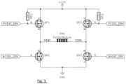
Figure 3 illustrates a circuit layout for a thermoelectric device. - The following description presents exemplary embodiments and, together with the drawings, serves to explain principles of the invention. However, the scope of the invention is not intended to be limited to the precise details of the embodiments or exact adherence with all system features and/or method steps, since variations will be apparent to a skilled person and are deemed also to be covered by the description. Terms for components used herein should be given a broad interpretation that also encompasses equivalent functions and features.
- In some cases, several alternative terms (synonyms) for structural, system features have been provided but such terms are not intended to be exhaustive. For the avoidance of doubt, any terms separated by the "/" symbol generally refer to alternative "or" expressions where the terms can be used interchangeably. Descriptive terms should also be given the broadest possible interpretation; e.g. the term "comprising" as used in this specification means "consisting at least in part of" such that interpreting each statement in this specification that includes the term "comprising", features other than that or those prefaced by the term may also be present. Related terms such as "comprise" and "comprises" are to be interpreted in the same manner. Any directional terms such as "vertical", "horizontal", "up", "down", "sideways", "upper" and "lower" are used for convenience of explanation usually with reference to the form shown in illustrations and are not intended to be ultimately limiting if an equivalent function can be achieved with an alternative dimension and/or direction. All directional terms are relative to each other.
- The description herein refers to embodiments with particular combinations of steps or features, however, it is envisaged that further combinations and cross-combinations of compatible steps or features between embodiments will be possible. Indeed, isolated features may function independently as an invention from other features and not necessarily require implementation as a complete combination.
- It will be understood that the illustrated embodiments show applications only for the purposes of explanation. In practice, the invention may be applied to many different configurations, where the embodiment is straightforward for those skilled in the art to implement.
-
Figure 1 shows the main components for implementing a system for testing, primarily a camera housing generally denoted 10, including: a temperature isolatedenclosure 11, a Peltiermodule 12 and acamera module 13 embedded in theenclosure 11 for optimal temperature distribution. -
Enclosure 11 may be formed as a box housing with aremoveable cover 14, such that during assembly the camera module and other components may be accessed from a frontal position.Cover 14 has an opening 21 serving as a window to align with the camera lens. - Also visible in
Figure 1 : a window lens 15 (e.g. of glass or other suitable transparent material), alens heater ring 16, aPCB 17 comprising control electronics, aradiator 18 that is connectable to a rear wall/heat exchanging surface of thehousing 11 sandwichingPeltier module 12 therebetween, and afan unit 19. Aport 20 provides side access tohousing 11 for the connection of cables to the internal devices. As such the control electronics may be resident within the housing, externally (communicating to components through the port) or a combination thereof. - In the illustrated form, the walls of
enclosure 11 are formed with low thermal conductive properties, e.g. as a multi-chambered wall such as shown byFigure 2 . The chambers may form a honeycomb as shown, or other suitable geometric shapes, to exemplify closed air cells. Theenclosure 11 may be dimensioned to snugly accommodate the camera module and can be 3D printed for customisation to a particular camera module's dimensions. The walls ofenclosure 11 are configured to achieve good levels of thermal isolation. In alternative forms the walls may be comprised of a composite structure and/or incorporation of material with extremely low thermal conductivity, such as a synthetic porous layer, e.g. Aerogel®. - The walls allow for better thermal isolation of the camera in a climatic chamber environment and, thus, provides a significant reduction in power dissipation. A lower power requirement enables a smaller Peltier module.
- By way of an overview of operation, the camera module may be activated when a temperature within the enclosure is at an optimum operating parameter, enabled by the Peltier module. This may further include activation of the
lens heating ring 16 which warms thelens 15 and mitigates fogging. Thefan unit 19 may also be activated, particularly for improving thermal transfer fromradiator 18 to the surrounding environment (e.g. in a climatic chamber) when it is heated/cooled byPeltier module 12. - By implementing a hermetic structure according to the above, an isolated environment within the housing is created, independent of external conditions, i.e. where a camera and all electronics and optics maintains the same stable working point which leads to identical image quality results. Such considerations especially configure it for use in visual inspection procedures of a monitored product for quality assurance.
- Furthermore, use of a Peltier module mitigates interference in the camera under testing conditions, while the multi-chamber thermal insulation of the box walls reduces impact on the environmental conditions inside the test area. A PID (proportional-integral-derivative) regulator may be implemented to achieve desired conditions inside camera, independent of external environment, wherein regulator calibration and diagnostic function may be available on a UART console.
- Referring to
Figure 3 and according to one example, the control circuit may use an H-Bridge to change the direction of current flow through the Peltier module and thus alternately heat or cool the camera module respectively, depending on external conditions. - The temperature inside the camera box may be regulated by a microcontroller (e.g. with an implemented PID regulator) connected to a temperature sensor. A PID algorithm compares two values: a set temperature and an actual Temperature. According to the difference between these two values, a new value of regulation is calculated (to determine heating or cooling). This enables a desired temperature to be achieved independent of external conditions and with negligible fluctuation. The foregoing step response is an example of general PID control to better explain the working principle of the regulator mechanism, which reacts quickly to temperature changes with negligible fluctuation and reaches a stable state to maintain a constant temperature of the camera.
- By implementation of a universal asynchronous receiver-transmitter (UART) interface, a user may change settings stored in a non-volatile memory (such as the temperature inside the camera box) to parameters most optimal for the chosen camera. If settings are not modified the temperature adaptation may be configured with default predefined values.
- According to the invention, the problem with dimensional expansion of optical elements is eliminated by a constant temperature control described above. However, even while a stable temperature may be maintained within the housing, for ensuring optimal operation of the camera and its electronics, the camera lens and/or window opening in the box may still be subject to condensation due to temperature differential. Accordingly, the problem of lens fogging may be addressed by heating the glass lens with a dedicated ring (e.g. aluminium lens ring 16) with a ceramic heater controlled by the same microcontroller as the Peltier module.
- Since electrical power may be used to operate all temperature regulation and lens heating functions, the present solution reduces the mediums that need to be used to only one, i.e. electricity only instead of both electricity and compressed air known from prior art solutions. This outcome simplifies the overall construction and resources needed for the device. Furthermore, the operator using the device for test purposes has more flexibility regarding the placement of the camera inside a climatic chamber. There is also significant noise reduction during operation compared to a compressed air system.
- The invention enables a method of testing within a climatic chamber. For example, including the steps of positioning the camera housing so the camera lens has a field of view covering an article to be tested, closing the climatic chamber and setting a target internal temperature thereof, meanwhile a determined operating temperature of the camera is known and an internal space of the housing may be maintained at said determined operating temperature. In embodiments, as the target chamber temperature is known along with the actual current ambient temperature in the chamber, the controller can cause activation of the Peltier module in response/anticipation thereto (i.e. before a target temperature is reached). For example, if the temperature in the chamber is to be very low, the Peltier module can be activated to heat the camera module with immediate effect, i.e. before the external temperature reaches the extreme. Conversely, if the target temperature is to be very high, the Peltier module can be activated to cool the camera module. In this way, monitoring and adjustment of temperature is dynamic and reactive to conditions in the more expedient way to operate the sensor optimally.
- By way of summary, a camera system for testing in harsh climatic conditions is described herein. The camera housing includes a cavity for a camera module, a window for alignment with a lens of the camera module, a thermal electric device (e.g. a Peltier module) with a first side configured for thermal communication with the camera module inside the housing and a second side configured for thermal communication outside the housing. There is provision for an external temperature sensor to communicate a signal to a controller corresponding to an external temperature, for activation of the thermal electric device in response thereto. At least the second side of the thermal electric device may be in contact with a radiator or heat sink element for dissipation/absorption of thermal energy generated by the thermal electric device.
- By way of further summary, a camera/sensor housing provides an isolated stable temperature environment for a camera/sensor, enabling it to be operated in a range of temperatures. This may be helpful in a testing environment, e.g. for the purposes of detecting defects in products, or other uses. A camera is accommodated in an insulated enclosure and a Peltier module is controlled to provide or remove heat from the enclosure/camera so as to maintain a stable temperature independent of an environmental temperature within a climatic chamber where a product is to be monitored. A lens heater may mitigate fogging of the lens in use.
- Several benefits are possible by implementation of the invention, namely:
- since image quantization quality is strongly connected with temperature, i.e. true color identification, maintenance of a stable temperature within the housing, in response to a changing external temperature, will preserve image quality;
- constant/stable environmental conditions eliminate problems with thermal expansion of optical component which can effect image quality, thus reducing interference;
- there is no limitation for type of cameras used, as a housing can be formed (e.g. 3D printed) to accommodate any type of camera;
- diagnostic information's plug and play possibilities for image comparison allow detection of issues without impediment;
- easily mountable by suitable external surface features on housing;
- potential for application with other sensor types, i.e. an isolated environment can be applied to other sensors/modules than an optical sensor such as a camera described herein; for example, where a stable operation point required in a car where a module has to perform a function for critical decisions and temperature could influence results.
Claims (15)
- A sensor housing for a sensor module, comprising:an insulated internal volume configured for accommodating the sensor module therein;a thermal electric device configured for alternatively heating and cooling the internal volume and/or sensor module.
- The sensor housing of claim 1, wherein the thermal electric device comprises a first side configured for thermal communication with the internal volume and/or sensor module and a second side configured for thermal communication with a radiator at an outer wall of the housing.
- The sensor housing of claim 1 or 2, further comprising a fan unit for supplying air onto the radiator.
- The sensor housing according to any of claims 1 to 3, further comprising an electric lens heating element at or proximate an opening for aligning with the sensor module.
- The sensor housing according to any of claims 1 to 4, in combination with a controller for controlling the thermal electric device to regulate temperature within the internal volume.
- The sensor housing according to any of claims 1 to 5, further comprising a port for receiving electrical connections therethrough.
- The sensor housing according to any of claims 1 to 6, comprising the sensor module.
- A system for visually inspecting an article in in a range of climatic conditions, comprising:the sensor housing of any of preceding claims 1 to 4;a sensor module; anda controller configured for controlling the thermal electric device to be energised for maintaining a temperature of the internal volume of the enclosure and/or sensor module corresponding to a recommended operating temperature of the sensor module, in response to an external temperature outside the enclosure.
- The system according to claim 8, wherein the thermal electric device is a Peltier module with a first side configured for thermal communication with the internal volume of the enclosure and/or camera module and a second side configured for thermal communication to outside the enclosure.
- The system according to claim 8 or 9, wherein the system comprises a radiator in thermal communication with the thermal electric device.
- The system according to any preceding claim 8 to 10, further comprising an electric lens heating element, operable by the controller.
- The system according to any preceding claim 7 to 11, wherein the insulated walls comprise a plurality of closed cells.
- A method of inspecting an article in a range of climatic conditions, comprising the steps of:positioning a sensor housing, according to the system of any of claims 8 to 12, within a climatic chamber so that the sensor module has a field of view covering the article to be tested;providing a range of climatic temperatures in the climatic chamber;controlling the thermal electric device to transfer to or remove heat from the sensor housing so as to maintain a temperature of the sensor module according to a recommended operating temperature, independent of the environmental temperature.
- The method of claim 13, further comprising the step of:operating the sensor module to capture an image of the article;inspecting the image to determine the presence of one or more defects in the article, as caused by the climatic temperature.
- The method of claim 14, further comprising the step of heating a lens of the sensor module to mitigate condensation.
Priority Applications (3)
| Application Number | Priority Date | Filing Date | Title |
|---|---|---|---|
| EP23174931.8A EP4467934A1 (en) | 2023-05-23 | 2023-05-23 | A sensor housing for a sensor module |
| CN202410615599.3A CN119031227A (en) | 2023-05-23 | 2024-05-17 | Sensor housing for sensor modules |
| US18/666,892 US12560551B2 (en) | 2023-05-23 | 2024-05-17 | Sensor housing for a sensor module |
Applications Claiming Priority (1)
| Application Number | Priority Date | Filing Date | Title |
|---|---|---|---|
| EP23174931.8A EP4467934A1 (en) | 2023-05-23 | 2023-05-23 | A sensor housing for a sensor module |
Publications (1)
| Publication Number | Publication Date |
|---|---|
| EP4467934A1 true EP4467934A1 (en) | 2024-11-27 |
Family
ID=86604064
Family Applications (1)
| Application Number | Title | Priority Date | Filing Date |
|---|---|---|---|
| EP23174931.8A Pending EP4467934A1 (en) | 2023-05-23 | 2023-05-23 | A sensor housing for a sensor module |
Country Status (3)
| Country | Link |
|---|---|
| US (1) | US12560551B2 (en) |
| EP (1) | EP4467934A1 (en) |
| CN (1) | CN119031227A (en) |
Citations (4)
| Publication number | Priority date | Publication date | Assignee | Title |
|---|---|---|---|---|
| DE102011122771A1 (en) * | 2011-10-22 | 2013-04-25 | Audi Ag | Protective camera housing for arranging camera of camera device in air-conditioned room, such as climate controlled chamber, with changing climatic conditions, has jacket provided with inner chamber and outer chamber |
| EP3675616A1 (en) * | 2018-12-26 | 2020-07-01 | Thales | System for protecting an electronic component |
| US20210333197A1 (en) * | 2020-04-28 | 2021-10-28 | Leica Microsystems Cms Gmbh | System for Microscopic Examination of an Incubated Sample |
| US20210400179A1 (en) * | 2020-06-18 | 2021-12-23 | Ford Global Technologies, Llc | Sensor system with cleaning and heating |
Family Cites Families (7)
| Publication number | Priority date | Publication date | Assignee | Title |
|---|---|---|---|---|
| US5864365A (en) * | 1996-01-26 | 1999-01-26 | Kaman Sciences Corporation | Environmentally controlled camera housing assembly |
| JP6596845B2 (en) | 2015-03-06 | 2019-10-30 | 株式会社リコー | Temperature control device, image display device, vehicle |
| CN210442511U (en) * | 2015-11-13 | 2020-05-01 | 菲力尔探测公司 | Dose rate measurement system |
| DE102017001461A1 (en) | 2017-02-08 | 2018-08-09 | Gebr. Krallmann Gmbh | Heating and / or cooling device for a solid or a fluid stream |
| US11397306B2 (en) | 2018-07-30 | 2022-07-26 | Magna Electronics Inc. | Vehicular camera with temperature invariant lens spacers |
| US10597002B1 (en) | 2018-09-21 | 2020-03-24 | Ford Global Technologies, Llc | Imaging system |
| US11733512B2 (en) | 2019-07-08 | 2023-08-22 | Ford Global Technologies, Llc | Sensor having a wireless heating system |
-
2023
- 2023-05-23 EP EP23174931.8A patent/EP4467934A1/en active Pending
-
2024
- 2024-05-17 US US18/666,892 patent/US12560551B2/en active Active
- 2024-05-17 CN CN202410615599.3A patent/CN119031227A/en active Pending
Patent Citations (4)
| Publication number | Priority date | Publication date | Assignee | Title |
|---|---|---|---|---|
| DE102011122771A1 (en) * | 2011-10-22 | 2013-04-25 | Audi Ag | Protective camera housing for arranging camera of camera device in air-conditioned room, such as climate controlled chamber, with changing climatic conditions, has jacket provided with inner chamber and outer chamber |
| EP3675616A1 (en) * | 2018-12-26 | 2020-07-01 | Thales | System for protecting an electronic component |
| US20210333197A1 (en) * | 2020-04-28 | 2021-10-28 | Leica Microsystems Cms Gmbh | System for Microscopic Examination of an Incubated Sample |
| US20210400179A1 (en) * | 2020-06-18 | 2021-12-23 | Ford Global Technologies, Llc | Sensor system with cleaning and heating |
Also Published As
| Publication number | Publication date |
|---|---|
| US12560551B2 (en) | 2026-02-24 |
| CN119031227A (en) | 2024-11-26 |
| US20240393257A1 (en) | 2024-11-28 |
Similar Documents
| Publication | Publication Date | Title |
|---|---|---|
| US9651428B2 (en) | Battery system temperature monitor | |
| CA2730080C (en) | Method and apparatus to accurately read ambient room temperature for a room sensor apparatus | |
| CN103080711B (en) | Infrared thermography and stabilization thereof | |
| KR20010039856A (en) | Infrared sensor stabilisable in temperature, and infrared thermometer with a sensor of this type | |
| US9219850B2 (en) | Monitoring camera | |
| GB2454755A (en) | Drywell temperature calibration system and method | |
| JP2020008370A (en) | Wind condition detection device | |
| US11885690B2 (en) | High-precision non-contact temperature measurement device | |
| CN111398340B (en) | Method and system for measuring radiation refrigeration material | |
| JPWO2020044484A1 (en) | In-vehicle camera device | |
| US12560551B2 (en) | Sensor housing for a sensor module | |
| CN109557743B (en) | Aerial camera focal plane temperature control system and control method thereof | |
| CN207067820U (en) | A kind of photomultiplier temperature control equipment | |
| US20070034799A1 (en) | Infrared sensor having thermo couple | |
| CN1220036C (en) | Refrigeration unit with temperature sensor | |
| KR20200083037A (en) | Thermal imaging apparatus | |
| JP2010175835A (en) | Camera apparatus | |
| CN101810064B (en) | Data transmission module | |
| CN213601877U (en) | Temperature control device of photoelectric detection device | |
| CN114323307B (en) | Infrared calibration device and testing equipment | |
| CN115144084B (en) | Temperature measuring device | |
| CN118778738A (en) | Tracker system and constant temperature control method | |
| CN111983765A (en) | Imaging device, temperature control device and temperature control method thereof | |
| EP1615065B1 (en) | Infrared camera | |
| CN207443005U (en) | InGaAs infrared cameras |
Legal Events
| Date | Code | Title | Description |
|---|---|---|---|
| PUAI | Public reference made under article 153(3) epc to a published international application that has entered the european phase |
Free format text: ORIGINAL CODE: 0009012 |
|
| STAA | Information on the status of an ep patent application or granted ep patent |
Free format text: STATUS: THE APPLICATION HAS BEEN PUBLISHED |
|
| AK | Designated contracting states |
Kind code of ref document: A1 Designated state(s): AL AT BE BG CH CY CZ DE DK EE ES FI FR GB GR HR HU IE IS IT LI LT LU LV MC ME MK MT NL NO PL PT RO RS SE SI SK SM TR |
|
| STAA | Information on the status of an ep patent application or granted ep patent |
Free format text: STATUS: REQUEST FOR EXAMINATION WAS MADE |
|
| 17P | Request for examination filed |
Effective date: 20241218 |