EP4467902A2 - Systèmes et procédés de régulation de la température de réfrigérant biphasique pompé - Google Patents
Systèmes et procédés de régulation de la température de réfrigérant biphasique pompé Download PDFInfo
- Publication number
- EP4467902A2 EP4467902A2 EP24176772.2A EP24176772A EP4467902A2 EP 4467902 A2 EP4467902 A2 EP 4467902A2 EP 24176772 A EP24176772 A EP 24176772A EP 4467902 A2 EP4467902 A2 EP 4467902A2
- Authority
- EP
- European Patent Office
- Prior art keywords
- refrigerant
- evaporator
- phase
- pump
- condenser
- Prior art date
- Legal status (The legal status is an assumption and is not a legal conclusion. Google has not performed a legal analysis and makes no representation as to the accuracy of the status listed.)
- Pending
Links
Images


Classifications
-
- F—MECHANICAL ENGINEERING; LIGHTING; HEATING; WEAPONS; BLASTING
- F25—REFRIGERATION OR COOLING; COMBINED HEATING AND REFRIGERATION SYSTEMS; HEAT PUMP SYSTEMS; MANUFACTURE OR STORAGE OF ICE; LIQUEFACTION SOLIDIFICATION OF GASES
- F25B—REFRIGERATION MACHINES, PLANTS OR SYSTEMS; COMBINED HEATING AND REFRIGERATION SYSTEMS; HEAT PUMP SYSTEMS
- F25B49/00—Arrangement or mounting of control or safety devices
- F25B49/02—Arrangement or mounting of control or safety devices for compression type machines, plants or systems
-
- F—MECHANICAL ENGINEERING; LIGHTING; HEATING; WEAPONS; BLASTING
- F25—REFRIGERATION OR COOLING; COMBINED HEATING AND REFRIGERATION SYSTEMS; HEAT PUMP SYSTEMS; MANUFACTURE OR STORAGE OF ICE; LIQUEFACTION SOLIDIFICATION OF GASES
- F25B—REFRIGERATION MACHINES, PLANTS OR SYSTEMS; COMBINED HEATING AND REFRIGERATION SYSTEMS; HEAT PUMP SYSTEMS
- F25B13/00—Compression machines, plants or systems, with reversible cycle
-
- F—MECHANICAL ENGINEERING; LIGHTING; HEATING; WEAPONS; BLASTING
- F25—REFRIGERATION OR COOLING; COMBINED HEATING AND REFRIGERATION SYSTEMS; HEAT PUMP SYSTEMS; MANUFACTURE OR STORAGE OF ICE; LIQUEFACTION SOLIDIFICATION OF GASES
- F25B—REFRIGERATION MACHINES, PLANTS OR SYSTEMS; COMBINED HEATING AND REFRIGERATION SYSTEMS; HEAT PUMP SYSTEMS
- F25B23/00—Machines, plants or systems, with a single mode of operation not covered by groups F25B1/00 - F25B21/00, e.g. using selective radiation effect
- F25B23/006—Machines, plants or systems, with a single mode of operation not covered by groups F25B1/00 - F25B21/00, e.g. using selective radiation effect boiling cooling systems
-
- A—HUMAN NECESSITIES
- A47—FURNITURE; DOMESTIC ARTICLES OR APPLIANCES; COFFEE MILLS; SPICE MILLS; SUCTION CLEANERS IN GENERAL
- A47L—DOMESTIC WASHING OR CLEANING; SUCTION CLEANERS IN GENERAL
- A47L13/00—Implements for cleaning floors, carpets, furniture, walls, or wall coverings
- A47L13/10—Scrubbing; Scouring; Cleaning; Polishing
- A47L13/20—Mops
- A47L13/22—Mops with liquid-feeding devices
-
- F—MECHANICAL ENGINEERING; LIGHTING; HEATING; WEAPONS; BLASTING
- F25—REFRIGERATION OR COOLING; COMBINED HEATING AND REFRIGERATION SYSTEMS; HEAT PUMP SYSTEMS; MANUFACTURE OR STORAGE OF ICE; LIQUEFACTION SOLIDIFICATION OF GASES
- F25B—REFRIGERATION MACHINES, PLANTS OR SYSTEMS; COMBINED HEATING AND REFRIGERATION SYSTEMS; HEAT PUMP SYSTEMS
- F25B1/00—Compression machines, plants or systems with non-reversible cycle
-
- F—MECHANICAL ENGINEERING; LIGHTING; HEATING; WEAPONS; BLASTING
- F25—REFRIGERATION OR COOLING; COMBINED HEATING AND REFRIGERATION SYSTEMS; HEAT PUMP SYSTEMS; MANUFACTURE OR STORAGE OF ICE; LIQUEFACTION SOLIDIFICATION OF GASES
- F25B—REFRIGERATION MACHINES, PLANTS OR SYSTEMS; COMBINED HEATING AND REFRIGERATION SYSTEMS; HEAT PUMP SYSTEMS
- F25B25/00—Machines, plants or systems, using a combination of modes of operation covered by two or more of the groups F25B1/00 - F25B23/00
-
- F—MECHANICAL ENGINEERING; LIGHTING; HEATING; WEAPONS; BLASTING
- F25—REFRIGERATION OR COOLING; COMBINED HEATING AND REFRIGERATION SYSTEMS; HEAT PUMP SYSTEMS; MANUFACTURE OR STORAGE OF ICE; LIQUEFACTION SOLIDIFICATION OF GASES
- F25B—REFRIGERATION MACHINES, PLANTS OR SYSTEMS; COMBINED HEATING AND REFRIGERATION SYSTEMS; HEAT PUMP SYSTEMS
- F25B41/00—Fluid-circulation arrangements
- F25B41/20—Disposition of valves, e.g. of on-off valves or flow control valves
-
- F—MECHANICAL ENGINEERING; LIGHTING; HEATING; WEAPONS; BLASTING
- F25—REFRIGERATION OR COOLING; COMBINED HEATING AND REFRIGERATION SYSTEMS; HEAT PUMP SYSTEMS; MANUFACTURE OR STORAGE OF ICE; LIQUEFACTION SOLIDIFICATION OF GASES
- F25B—REFRIGERATION MACHINES, PLANTS OR SYSTEMS; COMBINED HEATING AND REFRIGERATION SYSTEMS; HEAT PUMP SYSTEMS
- F25B5/00—Compression machines, plants or systems, with several evaporator circuits, e.g. for varying refrigerating capacity
- F25B5/02—Compression machines, plants or systems, with several evaporator circuits, e.g. for varying refrigerating capacity arranged in parallel
-
- G—PHYSICS
- G06—COMPUTING OR CALCULATING; COUNTING
- G06F—ELECTRIC DIGITAL DATA PROCESSING
- G06F1/00—Details not covered by groups G06F3/00 - G06F13/00 and G06F21/00
- G06F1/16—Constructional details or arrangements
- G06F1/20—Cooling means
-
- H—ELECTRICITY
- H05—ELECTRIC TECHNIQUES NOT OTHERWISE PROVIDED FOR
- H05K—PRINTED CIRCUITS; CASINGS OR CONSTRUCTIONAL DETAILS OF ELECTRIC APPARATUS; MANUFACTURE OF ASSEMBLAGES OF ELECTRICAL COMPONENTS
- H05K7/00—Constructional details common to different types of electric apparatus
- H05K7/20—Modifications to facilitate cooling, ventilating, or heating
- H05K7/20709—Modifications to facilitate cooling, ventilating, or heating for server racks or cabinets; for data centers, e.g. 19-inch computer racks
- H05K7/208—Liquid cooling with phase change
- H05K7/20818—Liquid cooling with phase change within cabinets for removing heat from server blades
-
- H—ELECTRICITY
- H05—ELECTRIC TECHNIQUES NOT OTHERWISE PROVIDED FOR
- H05K—PRINTED CIRCUITS; CASINGS OR CONSTRUCTIONAL DETAILS OF ELECTRIC APPARATUS; MANUFACTURE OF ASSEMBLAGES OF ELECTRICAL COMPONENTS
- H05K7/00—Constructional details common to different types of electric apparatus
- H05K7/20—Modifications to facilitate cooling, ventilating, or heating
- H05K7/20709—Modifications to facilitate cooling, ventilating, or heating for server racks or cabinets; for data centers, e.g. 19-inch computer racks
- H05K7/20836—Thermal management, e.g. server temperature control
-
- F—MECHANICAL ENGINEERING; LIGHTING; HEATING; WEAPONS; BLASTING
- F25—REFRIGERATION OR COOLING; COMBINED HEATING AND REFRIGERATION SYSTEMS; HEAT PUMP SYSTEMS; MANUFACTURE OR STORAGE OF ICE; LIQUEFACTION SOLIDIFICATION OF GASES
- F25B—REFRIGERATION MACHINES, PLANTS OR SYSTEMS; COMBINED HEATING AND REFRIGERATION SYSTEMS; HEAT PUMP SYSTEMS
- F25B2400/00—General features or devices for refrigeration machines, plants or systems, combined heating and refrigeration systems or heat-pump systems, i.e. not limited to a particular subgroup of F25B
- F25B2400/23—Separators
-
- F—MECHANICAL ENGINEERING; LIGHTING; HEATING; WEAPONS; BLASTING
- F25—REFRIGERATION OR COOLING; COMBINED HEATING AND REFRIGERATION SYSTEMS; HEAT PUMP SYSTEMS; MANUFACTURE OR STORAGE OF ICE; LIQUEFACTION SOLIDIFICATION OF GASES
- F25B—REFRIGERATION MACHINES, PLANTS OR SYSTEMS; COMBINED HEATING AND REFRIGERATION SYSTEMS; HEAT PUMP SYSTEMS
- F25B2700/00—Sensing or detecting of parameters; Sensors therefor
- F25B2700/21—Temperatures
- F25B2700/2117—Temperatures of an evaporator
- F25B2700/21174—Temperatures of an evaporator of the refrigerant at the inlet of the evaporator
Definitions
- the present disclosure relates generally to cooling systems, such as those used in data centers, and more specifically relates to pumped two-phase refrigerant cooling systems.
- Phase change heat transfer (often referred to as Pumped Two-Phase (P2P)), such as evaporation in a directly mounted (to the chip) two-phase cold plate (2PCP), appears to offer the most effective thermal transfer.
- P2P Pumped Two-Phase
- 2PCP two-phase cold plate
- the first heat transfer is to remove the subcooling.
- This single-phase heat transfer occurs with a heat transfer coefficient (HTC) that is much smaller that the HTC of phase change (evaporative) heat transfer.
- HTC heat transfer coefficient
- single-phase heat transfer can diminish the 2PCP performance and can create hot spots which can cause CPU thermal throttling, loss of performance, and/or other failures.
- a system for controlling pumped two-phase refrigerant temperature can include a pump configured to pump a refrigerant through an evaporator in thermal communication with a heat load, a condenser in fluid communication with the pump and the evaporator, a controller configured to control a temperature of the refrigerant entering the evaporator to minimize single-phase cooling in the evaporator, or any combination thereof.
- refrigerant within the evaporator can be heated by the heat load, thereby causing at least some of the refrigerant to change from a liquid phase to a vapor phase.
- the condenser can be configured to cool the refrigerant fluidically downstream from the evaporator, thereby causing at least some of the refrigerant to change from the vapor phase to the liquid phase before returning to the pump.
- a system for controlling pumped two-phase refrigerant temperature can further include a compressor configured to inject the refrigerant in the vapor phase fluidically between the pump and the evaporator.
- a system for controlling pumped two-phase refrigerant temperature can further include a separator configured to separate refrigerant extracted fluidically between the evaporator and the condenser into a portion of the refrigerant in the vapor phase and a portion of the refrigerant in the liquid phase.
- the separator can be configured to inject the portion of the refrigerant in the liquid phase fluidically between the pump and the condenser.
- the controller can be configured to control a speed of the compressor according to the temperature of the refrigerant entering the evaporator. In at least one example, the controller can be configured to monitor the temperature and pressure of the refrigerant entering the evaporator. In at least one example, the controller can be configured to control a valve downstream of the compressor according to the temperature of the refrigerant entering the evaporator.
- a system for controlling pumped two-phase refrigerant temperature can include a plurality of two-phase cold plates, a pump configured to pump a refrigerant through the plurality of two-phase cold plates, a condenser in fluid communication with the pump and the plurality of two-phase cold plates, a separator in fluid communication with the condenser and the plurality of two-phase cold plates, a compressor configured to inject the portion of the refrigerant in the vapor phase fluidically between the pump and the plurality of two-phase cold plates, a controller configured to control the speed of the compressor to minimize single-phase cooling in the plurality of two-phase cold plates, or any combination thereof.
- any or all of the two-phase cold plates can be in thermal communication with a heat load. In at least one example, any or all of the two-phase cold plates can be plumbed in parallel fluid communication with one another. In at least one example, any or all of the two-phase cold plates can be plumbed in series fluid communication with one another. In at least one example, any or all of the plurality of two-phase cold plates can be heated, by the heat load(s), thereby causing at least some of the refrigerant to change from a liquid phase to a vapor phase. In at least one example, the controller can be configured to monitor the temperature and/or pressure of refrigerant entering the plurality of two-phase cold plates.
- the condenser can be configured to cool the refrigerant fluidically downstream from the plurality of two-phase cold plates, thereby causing the refrigerant to change from the vapor phase to the liquid phase before returning to the pump.
- the separator can be configured to extract some of the refrigerant fluidically between the condenser and the plurality of two-phase cold plates.
- the separator can be configured to separate the extracted refrigerant into a portion of the refrigerant in the vapor phase and a portion of the refrigerant in the liquid phase.
- the separator can be configured to inject the portion of the refrigerant in the liquid phase fluidically between the pump and the condenser.
- a method of controlling a temperature of a refrigerant can include pumping, such as with a pump, the refrigerant through an evaporator, thereby heating the refrigerant and causing at least some of the refrigerant to change from a liquid phase to a vapor phase, cooling the refrigerant in a condenser fluidically downstream from the evaporator, thereby causing at least some of the refrigerant to change from the vapor phase to the liquid phase before returning to the pump, extracting a portion of the refrigerant in the vapor phase fluidically between the evaporator and the condenser, injecting the extracted portion of the refrigerant, in the vapor phase, fluidically between the pump and the evaporator, thereby increasing the temperature of the refrigerant entering the evaporator, or any combination thereof.
- the evaporator can be in thermal communication with a heat load.
- injecting the extracted portion of the refrigerant in the vapor phase can include compressing, such as with a compressor, the extracted portion of the refrigerant in the vapor phase.
- a method of controlling a temperature of a refrigerant can further include separating the extracted portion of the refrigerant extracted between the evaporator and the condenser into the portion of the refrigerant in the vapor phase and a portion of the refrigerant in the liquid phase.
- a method of controlling a temperature of a refrigerant can further include injecting the portion of the refrigerant in the liquid phase fluidically between the pump and the condenser. In at least one example, a method of controlling a temperature of a refrigerant can further include controlling a speed of the compressor according to the temperature of the refrigerant entering the evaporator. In at least one example, a method of controlling a temperature of a refrigerant can further include monitoring the temperature and pressure of the refrigerant entering the evaporator. In at least one example, a method of controlling a temperature of a refrigerant can further include controlling a valve fluidically downstream of the compressor according to the temperature of the refrigerant entering the evaporator.
- a method of controlling a temperature of a refrigerant can include ensuring that the extracted portion of the refrigerant extracted between the evaporator and the condenser is in the vapor phase. In at least one example, a method of controlling a temperature of a refrigerant can include ensuring that the extracted portion of the refrigerant extracted between the evaporator and the condenser is not in the liquid phase. In at least one example, a method of controlling a temperature of a refrigerant can include minimizing single-phase cooling in the evaporator by controlling the temperature of the refrigerant entering the evaporator.
- Couple can include any method or device for securing, binding, bonding, fastening, attaching, joining, inserting therein, forming thereon or therein, communicating, or otherwise associating, for example, mechanically, magnetically, electrically, chemically, operably, directly or indirectly with intermediate elements, one or more pieces of members together and can further include without limitation integrally forming one functional member with another in a unity fashion.
- the coupling can occur in any direction, including rotationally.
- all parts and components of the disclosure that are capable of being physically embodied inherently include imaginary and real characteristics regardless of whether such characteristics are expressly described herein, including but not limited to characteristics such as axes, ends, inner and outer surfaces, interior spaces, tops, bottoms, sides, boundaries, dimensions (e.g., height, length, width, thickness), mass, weight, volume and density, among others.
- each block in a flowchart may represent a module, segment, or portion of code, which can include one or more executable instructions for implementing the specified logical function(s).
- the function(s) noted in the block(s) might occur out of the order depicted in the figures.
- blocks shown in succession may, in fact, be executed substantially concurrently.
- each block of a flowchart illustration can be implemented by special purpose hardware-based systems that perform the specified functions or acts, or combinations of special purpose hardware and computer instructions.
- a system can include one or more pumps for pumping refrigerant through one or more evaporators in thermal communication with one or more heat loads, one or more condensers, and one or more controllers for controlling a temperature of the refrigerant(s) at one or more points in the system, such as at an evaporator inlet, for minimizing single-phase cooling in the evaporator.
- refrigerant can be heated, thereby causing at least some of the refrigerant to change from a liquid phase to a vapor phase.
- a condenser can be configured to cool the refrigerant fluidically downstream from an evaporator, thereby causing at least some of the refrigerant to change from the vapor phase to the liquid phase before returning to a pump.
- a system for controlling pumped two-phase refrigerant temperature can include a compressor configured to inject refrigerant in the vapor phase fluidically between a pump and an evaporator.
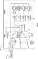
- FIG. 1 is a process flow diagram of one of many examples of a system for controlling a temperature of a refrigerant according to the disclosure.
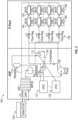
- FIG. 2 is a process flow diagram of another of many examples of a system for controlling a temperature of a refrigerant according to the disclosure.
- FIG. 3 is a process flow diagram of still another of many examples of a system for controlling a temperature of a refrigerant according to the disclosure.
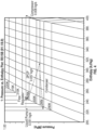
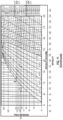
- FIG. 4 is a non-limiting exemplary pressure/enthalpy plot for one of many examples of a system and/or method for controlling a temperature of a refrigerant according to the disclosure.
- FIG. 1 is a process flow diagram of one of many examples of a system for controlling a temperature of a refrigerant according to the disclosure.
- FIG. 2 is a process flow diagram of another of many examples of a system for controlling a temperature of a refrigerant according to the disclosure.
- FIG. 3 is a process flow diagram of still another of many examples of a
- FIG. 5 is another non-limiting exemplary pressure/enthalpy plot for one of many examples of a system and/or method for controlling a temperature of a refrigerant according to the disclosure.
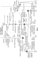
- FIG. 6 is a model of one of many examples of a system for controlling a temperature of a refrigerant according to the disclosure.
- FIG. 7 is a close-up view of the upper left quadrant of the model of FIG. 6 .
- FIG. 8 is a close-up view of the upper right quadrant of the model of FIG. 6 .
- FIG. 9 is a close-up view of the lower left quadrant of the model of FIG. 6 .
- FIG. 10 is a close-up view of the lower right quadrant of the model of FIG. 6 .
- FIG. 11 is another non-limiting exemplary pressure/enthalpy plot for one of many examples of a system and/or method for controlling a temperature of a refrigerant according to the disclosure.
- FIGS. 1-11 are described in conjunction with one another.
- a system 100 such as a system for controlling a heat transfer system, a system for cooling, or a system for controlling pumped two-phase refrigerant and/or refrigerant temperature, can include a pump 102 configured to pump a refrigerant through an evaporator 104 in thermal communication with a heat load 106, a condenser 108 in fluid communication with the pump 102 and the evaporator 104, a controller 110 configured to control a temperature of the refrigerant entering or returning to the evaporator 104 to minimize single-phase cooling in the evaporator 104, or any combination thereof.
- the heat load(s) 106 can be one or more Central Processing Unit(s) (CPUs), Graphics Processing Unit(s) (GPUs), other equipment one might find in a data center, or any combination thereof.
- heat from the heat load(s) 106 can heat refrigerant within the evaporator(s) 104, thereby causing at least some of the refrigerant to change from a liquid phase to a vapor phase.
- the evaporator(s) 104 can be or include two-phase cold plates, which can be in thermal communication with one or more CPUs and/or GPUs.
- any or all of the evaporator(s) 104 can be plumbed in parallel fluid communication with one or more other evaporators 104, such as through one or more manifolds 126 and/or one or more flow regulators 128. In at least one example, any or all of the evaporator(s) 104 can be plumbed in series fluid communication with one or more other evaporators 104, such as through one or more manifolds 126 and/or one or more flow regulators 128.
- any or all of the evaporator(s) 104 can be plumbed in parallel and series fluid communication with one or more other evaporators 104, such as through one or more manifolds 126 and/or one or more flow regulators 128.
- the condenser 108 can be configured to cool the refrigerant fluidically downstream from the evaporator 104, thereby causing at least some of the refrigerant to change from the vapor phase to the liquid phase before returning to the pump 102.
- the condenser 108 can be a liquid-to-liquid heat exchanger and/or may be cooled by a chilled water cooling system 120.
- the condenser 108 can be a liquid-to-air heat exchanger and/or may be air cooled.
- the condenser 108 can be a brazed plate heat exchanger.
- the condenser 108 can be a cold plate cooled by an external cooling system 120.
- a system 100 for controlling pumped two-phase refrigerant temperature can further include a compressor 112 configured to inject the refrigerant in the vapor phase fluidically between the pump 102 and the evaporator 104.
- the controller 110 can be configured to control a speed of the compressor 112, such as through the use of a variable frequency drive (VFD) 122, according to the temperature of the refrigerant entering or returning to the evaporator 104.
- VFD variable frequency drive
- the controller 110 can be configured to monitor the temperature and pressure of the refrigerant entering or returning to the evaporator 104.
- the controller 110 can be configured to control a valve 124 downstream of the compressor 112 according to the temperature of the refrigerant entering or returning to the evaporator 104.
- valve 124 can limit or prevent liquid backflow through compressor 112.
- refrigerant pressure downstream of pump 102 can be, and typically will be, higher than refrigerant pressure at separator 114, such that refrigerant downstream of pump 102 may be inclined to backflow into compressor 112 in the absence of valve 124, which could, for example, reduce system efficiency and/or cause damage to compressor 112.
- valve 124 can be or include one or more electrically or electronically controlled valves (see, e.g., FIG. 1 ).
- valve 124 can be or include one or more check valves (see, e.g., FIGS. 2-3 ), whether separately or in combination with one another and/or with one or more electrically or electronically controlled valves.
- one or more controller(s) 110 can be or include a Liebert° iCOM TM cooling unit controller, or another controller capable of operation in accordance with an example of the present disclosure.
- a system 100 for controlling pumped two-phase refrigerant temperature can further include a separator 114 configured to separate refrigerant extracted fluidically between the evaporator 104 and the condenser 108 into a portion of the refrigerant in the vapor phase and a portion of the refrigerant in the liquid phase.
- the separator 114 can be configured to inject the portion of the refrigerant in the liquid phase fluidically between the pump 102 and the condenser 108.
- the separator 114 can be configured to extract only refrigerant in the vapor phase, such as by taking refrigerant from a top-most (or otherwise configured) vapor port of a vessel and/or plumbing, thereby combining extraction and separation.
- one or more evaporators 104 can be or include one or more cold plates.
- a system 100 for controlling pumped two-phase refrigerant temperature can include a plurality of two-phase cold plates 104, a pump 102 configured to pump refrigerant through the plurality of two-phase cold plates 104, a condenser 108 in fluid communication with the pump 102 and the plurality of two-phase cold plates 104, a separator 114 in fluid communication with the condenser 108 and the plurality of two-phase cold plates 104, a compressor 112 configured to inject the portion of the refrigerant in the vapor phase fluidically between the pump 102 and the plurality of two-phase cold plates 104, a controller 110 configured to control the speed of the compressor 112 to minimize single-phase cooling in the two-phase cold plates 104, or any combination thereof.
- any or all of the two-phase cold plates 104 can be in thermal communication with one or more heat loads 106, such as a CPU, GPU, other computing equipment, or any combination thereof.
- any or all of the two-phase cold plates 104 can be plumbed in parallel and/or series fluid communication with one another, such as through one or more manifolds 126 and/or one or more flow regulators 128.
- refrigerant within any or all of the plurality of two-phase cold plates 104 can by heated, by way of heat transfer with one or more heat load(s) 106, thereby causing at least some of the refrigerant to change from a liquid phase to a vapor phase.
- the controller 110 can be configured to monitor the temperature and pressure of the refrigerant entering or returning to the evaporator.
- the condenser 108 can be configured to cool the refrigerant fluidically downstream from the plurality of two-phase cold plates 104, thereby causing the refrigerant to change from the vapor phase to the liquid phase before returning to the pump 102.
- the separator 114 can be configured to extract some of the refrigerant fluidically between the condenser 108 and the plurality of two-phase cold plates 104.
- the separator 114 can be configured to separate the extracted refrigerant into a portion of the refrigerant in the vapor phase and a portion of the refrigerant in the liquid phase.
- the separator 114 can be configured to inject the portion of the refrigerant in the liquid phase fluidically between the pump 102 and the condenser 108. In at least one example, the separator 114 can be configured to extract only refrigerant in the vapor phase.
- a method according to the disclosure can include pumping, such as with a pump 102, the refrigerant through an evaporator 104, thereby heating the refrigerant and causing at least some of the refrigerant to change from a liquid phase to a vapor phase, cooling the refrigerant in a condenser 108 fluidically downstream from the evaporator 104, thereby causing at least some of the refrigerant to change from the vapor phase to the liquid phase before returning to the pump 102, extracting a portion of the refrigerant in the vapor phase fluidically between the evaporator 104 and the condenser 108, injecting the extracted portion of the refrigerant, in the vapor phase, fluidically between the pump 102 and the evaporator 104, thereby increasing the temperature of the refrigerant
- the evaporator 104 can be in thermal communication with a heat load 106, such as a CPUs, GPUs, other equipment one might find in a data center, or any combination thereof.
- a heat load 106 such as a CPUs, GPUs, other equipment one might find in a data center, or any combination thereof.
- the evaporator(s) 104 can include two-phase cold plates, which can be in thermal communication with one or more CPUs and/or GPUs.
- injecting the extracted portion of the refrigerant in the vapor phase can include compressing, such as with a compressor 112, the extracted portion of the refrigerant in the vapor phase.
- a method of controlling a temperature of a refrigerant can further include separating the extracted portion of the refrigerant extracted between the evaporator 104 and the condenser 106 into the portion of the refrigerant in the vapor phase and a portion of the refrigerant in the liquid phase.
- a method of controlling a temperature of a refrigerant can further include injecting the portion of the refrigerant in the liquid phase fluidically between the pump 102 and the condenser 108.
- a method of controlling a temperature of a refrigerant can further include controlling a speed of the compressor 112, such as with a VFD 122, according to the temperature of the refrigerant entering, or returning to, the evaporator 104.
- a method of controlling a temperature of a refrigerant can further include monitoring the temperature and pressure of the refrigerant entering or returning to the evaporator 104.
- a method of controlling a temperature of a refrigerant can further include controlling a valve 124 fluidically downstream of the compressor 112 according to the temperature of the refrigerant entering or returning to the evaporator 104.
- valve 124 can limit or prevent liquid backflow through compressor 112, such as for avoiding damage to compressor 112.
- a method of controlling a temperature of a refrigerant can include ensuring that an extracted portion of refrigerant extracted between an evaporator 104 and a condenser 108 is in the vapor phase. In at least one example, a method of controlling a temperature of a refrigerant can include ensuring that the extracted portion of the refrigerant extracted between the evaporator 104 and the condenser 108 is not in the liquid phase. In at least one example, a method of controlling a temperature of a refrigerant can include minimizing single-phase cooling in the evaporator 104 by controlling the temperature of the refrigerant entering (returning to) the evaporator 104.
- a system for controlling pumped two-phase refrigerant temperature can include a pump configured to pump a refrigerant through an evaporator in thermal communication with a heat load, a condenser in fluid communication with the pump and the evaporator, a controller configured to control a temperature of the refrigerant entering the evaporator to minimize single-phase cooling in the evaporator, or any combination thereof.
- heat from the heat load can heat refrigerant in the evaporator, thereby causing at least some of the refrigerant to change from a liquid phase to a vapor phase.
- the condenser can be configured to cool the refrigerant fluidically downstream from the evaporator, thereby causing at least some of the refrigerant to change from the vapor phase to the liquid phase before returning to the pump.
- a system for controlling pumped two-phase refrigerant temperature can further include a compressor configured to inject the refrigerant in the vapor phase fluidically between the pump and the evaporator.
- a system for controlling pumped two-phase refrigerant temperature can further include a separator configured to separate refrigerant extracted fluidically between the evaporator and the condenser into a portion of the refrigerant in the vapor phase and a portion of the refrigerant in the liquid phase.
- the separator can be configured to inject the portion of the refrigerant in the liquid phase fluidically between the pump and the condenser.
- the controller can be configured to control a speed of the compressor according to the temperature of the refrigerant entering the evaporator. In at least one example, the controller can be configured to monitor the temperature and pressure of the refrigerant entering the evaporator. In at least one example, the controller can be configured to control a valve downstream of the compressor according to the temperature of the refrigerant entering the evaporator.
- a system for controlling pumped two-phase refrigerant temperature can include a plurality of two-phase cold plates, a pump configured to pump a refrigerant through the plurality of two-phase cold plates, a condenser in fluid communication with the pump and the plurality of two-phase cold plates, a separator in fluid communication with the condenser and the plurality of two-phase cold plates, a compressor configured to inject the portion of the refrigerant in the vapor phase fluidically between the pump and the plurality of two-phase cold plates, a controller configured to control the speed of the compressor to minimize single-phase cooling in the plurality of two-phase cold plates, or any combination thereof.
- any or all of the two-phase cold plates can be in thermal communication with a heat load. In at least one example, any or all of the two-phase cold plates can be plumbed in parallel fluid communication with one another. In at least one example, any or all of the two-phase cold plates can be plumbed in series fluid communication with one another. In at least one example, heat from the heat load(s) can heat refrigerant within any or all of the plurality of two-phase cold plates, thereby causing at least some of the refrigerant to change from a liquid phase to a vapor phase. In at least one example, the controller can be configured to monitor the temperature and/or pressure of the refrigerant entering one or more of a plurality of two-phase cold plates.
- the condenser can be configured to cool the refrigerant fluidically downstream from the plurality of two-phase cold plates, thereby causing the refrigerant to change from the vapor phase to the liquid phase before returning to the pump.
- the separator can be configured to extract some of the refrigerant fluidically between the condenser and the plurality of two-phase cold plates.
- the separator can be configured to separate the extracted refrigerant into a portion of the refrigerant in the vapor phase and a portion of the refrigerant in the liquid phase.
- the separator can be configured to inject the portion of the refrigerant in the liquid phase fluidically between the pump and the condenser.
- a method of controlling a temperature of a refrigerant can include pumping, such as with a pump, the refrigerant through an evaporator, thereby heating the refrigerant and causing at least some of the refrigerant to change from a liquid phase to a vapor phase, cooling the refrigerant in a condenser fluidically downstream from the evaporator, thereby causing at least some of the refrigerant to change from the vapor phase to the liquid phase before returning to the pump, extracting a portion of the refrigerant in the vapor phase fluidically between the evaporator and the condenser, injecting the extracted portion of the refrigerant, in the vapor phase, fluidically between the pump and the evaporator, thereby increasing the temperature of the refrigerant entering the evaporator, or any combination thereof.
- the evaporator can be in thermal communication with a heat load.
- injecting the extracted portion of the refrigerant in the vapor phase can include compressing, such as with a compressor, the extracted portion of the refrigerant in the vapor phase.
- a method of controlling a temperature of a refrigerant can further include separating the extracted portion of the refrigerant extracted between the evaporator and the condenser into the portion of the refrigerant in the vapor phase and a portion of the refrigerant in the liquid phase.
- a method of controlling a temperature of a refrigerant can further include injecting the portion of the refrigerant in the liquid phase fluidically between the pump and the condenser. In at least one example, a method of controlling a temperature of a refrigerant can further include controlling a speed of the compressor according to the temperature of the refrigerant entering the evaporator. In at least one example, a method of controlling a temperature of a refrigerant can further include monitoring the temperature and pressure of the refrigerant entering the evaporator. In at least one example, a method of controlling a temperature of a refrigerant can further include controlling a valve fluidically downstream of the compressor according to the temperature of the refrigerant entering the evaporator.
- a method of controlling a temperature of a refrigerant can include ensuring that the extracted portion of the refrigerant extracted between the evaporator and the condenser is in the vapor phase. In at least one example, a method of controlling a temperature of a refrigerant can include ensuring that the extracted portion of the refrigerant extracted between the evaporator and the condenser is not in the liquid phase. In at least one example, a method of controlling a temperature of a refrigerant can include minimizing single-phase cooling in the evaporator by controlling the temperature of the refrigerant entering the evaporator.
- the devices, systems and methods can be implemented for numerous different types and sizes in numerous different industries.
- the various methods and examples of the devices, systems and methods can be included in combination with each other to produce variations of the disclosed methods and examples. Discussion of singular elements can include plural elements and vice versa.
- the order of steps can occur in a variety of sequences unless otherwise specifically limited.
- the various steps described herein can be combined with other steps, interlineated with the stated steps, and/or split into multiple steps.
- elements have been described functionally and can be embodied as separate components or can be combined into components having multiple functions.
Landscapes
- Engineering & Computer Science (AREA)
- General Engineering & Computer Science (AREA)
- Physics & Mathematics (AREA)
- Thermal Sciences (AREA)
- Mechanical Engineering (AREA)
- Computer Hardware Design (AREA)
- Microelectronics & Electronic Packaging (AREA)
- Theoretical Computer Science (AREA)
- Human Computer Interaction (AREA)
- General Physics & Mathematics (AREA)
- Devices That Are Associated With Refrigeration Equipment (AREA)
- Sorption Type Refrigeration Machines (AREA)
Applications Claiming Priority (1)
| Application Number | Priority Date | Filing Date | Title |
|---|---|---|---|
| US202363503954P | 2023-05-23 | 2023-05-23 |
Publications (2)
| Publication Number | Publication Date |
|---|---|
| EP4467902A2 true EP4467902A2 (fr) | 2024-11-27 |
| EP4467902A3 EP4467902A3 (fr) | 2025-01-29 |
Family
ID=93529673
Family Applications (1)
| Application Number | Title | Priority Date | Filing Date |
|---|---|---|---|
| EP24176772.2A Pending EP4467902A3 (fr) | 2023-05-23 | 2024-05-17 | Systèmes et procédés de régulation de la température de réfrigérant biphasique pompé |
Country Status (3)
| Country | Link |
|---|---|
| US (1) | US20240393019A1 (fr) |
| EP (1) | EP4467902A3 (fr) |
| CN (1) | CN119022527A (fr) |
Family Cites Families (2)
| Publication number | Priority date | Publication date | Assignee | Title |
|---|---|---|---|---|
| WO2015065998A1 (fr) * | 2013-10-29 | 2015-05-07 | Arizona Board Of Regents On Behalf Of Arizona State University | Décalage de charge de crête au moyen d'un stockage d'énergie thermique à l'aide d'un thermosiphon |
| US10775110B2 (en) * | 2018-04-12 | 2020-09-15 | Rolls-Royce North American Technologies, Inc. | Tight temperature control at a thermal load with a two phase pumped loop, optionally augmented with a vapor compression cycle |
-
2024
- 2024-05-17 EP EP24176772.2A patent/EP4467902A3/fr active Pending
- 2024-05-21 US US18/670,716 patent/US20240393019A1/en active Pending
- 2024-05-23 CN CN202410647619.5A patent/CN119022527A/zh active Pending
Also Published As
| Publication number | Publication date |
|---|---|
| CN119022527A (zh) | 2024-11-26 |
| US20240393019A1 (en) | 2024-11-28 |
| EP4467902A3 (fr) | 2025-01-29 |
Similar Documents
| Publication | Publication Date | Title |
|---|---|---|
| EP3568650B1 (fr) | Gestion d'huile pour système de réfrigération de supermarché à micro-surpresseur | |
| EP2153156B1 (fr) | Système de refroidissement | |
| US9839163B2 (en) | Modular IT rack cooling assemblies and methods for assembling same | |
| CN103797315B (zh) | 用于制冷系统和方法的冷凝器蒸发器系统(ces) | |
| US20080223074A1 (en) | Refrigeration system | |
| CN103375847B (zh) | 数据机房的无油离心式冷却系统 | |
| EP3175185A1 (fr) | Système de refroidissement | |
| WO2008112568A2 (fr) | Compresseur | |
| CN111947336B (zh) | 一种制冷循环系统及其控制方法 | |
| CA2995951C (fr) | Systeme integre de refrigeration et conditionnement de l'air | |
| EP4286771A1 (fr) | Système de réfrigération | |
| EP4686327A1 (fr) | Système de refroidissement de liquide à deux phases | |
| CN103673437A (zh) | 一种兼具冷却功能的油回收装置及应用其的制冷系统 | |
| CN105393066B (zh) | Havc系统中的回油控制 | |
| CN103403477B (zh) | 致冷回路中的补油 | |
| EP4467902A2 (fr) | Systèmes et procédés de régulation de la température de réfrigérant biphasique pompé | |
| US20260016197A1 (en) | Modular chiller with pumped refrigerant economizer | |
| CN204404589U (zh) | 一种分级制冷设备 | |
| CN105571185A (zh) | 一种分级制冷设备 | |
| EP4671641A1 (fr) | Collecteur de condenseur à soupape de liquide | |
| US20260047052A1 (en) | Cabinet heat exchanger | |
| EP4679004A2 (fr) | Système de refroidissement à mode mixte | |
| EP4696952A2 (fr) | Procédés de confirmation de fonctionnement de pompe | |
| CN218972934U (zh) | 一种充冷服务装备 | |
| CN104807243A (zh) | 一种制冷装置 |
Legal Events
| Date | Code | Title | Description |
|---|---|---|---|
| PUAI | Public reference made under article 153(3) epc to a published international application that has entered the european phase |
Free format text: ORIGINAL CODE: 0009012 |
|
| STAA | Information on the status of an ep patent application or granted ep patent |
Free format text: STATUS: THE APPLICATION HAS BEEN PUBLISHED |
|
| AK | Designated contracting states |
Kind code of ref document: A2 Designated state(s): AL AT BE BG CH CY CZ DE DK EE ES FI FR GB GR HR HU IE IS IT LI LT LU LV MC ME MK MT NL NO PL PT RO RS SE SI SK SM TR |
|
| PUAL | Search report despatched |
Free format text: ORIGINAL CODE: 0009013 |
|
| AK | Designated contracting states |
Kind code of ref document: A3 Designated state(s): AL AT BE BG CH CY CZ DE DK EE ES FI FR GB GR HR HU IE IS IT LI LT LU LV MC ME MK MT NL NO PL PT RO RS SE SI SK SM TR |
|
| RIC1 | Information provided on ipc code assigned before grant |
Ipc: H05K 1/00 20060101ALI20241223BHEP Ipc: F25B 25/00 20060101ALI20241223BHEP Ipc: F25B 23/00 20060101ALI20241223BHEP Ipc: F25B 5/02 20060101ALI20241223BHEP Ipc: F25B 49/02 20060101ALI20241223BHEP Ipc: F25B 41/00 20210101AFI20241223BHEP |
|
| STAA | Information on the status of an ep patent application or granted ep patent |
Free format text: STATUS: REQUEST FOR EXAMINATION WAS MADE |
|
| 17P | Request for examination filed |
Effective date: 20250729 |
|
| STAA | Information on the status of an ep patent application or granted ep patent |
Free format text: STATUS: EXAMINATION IS IN PROGRESS |