EP4467887A1 - Method and system for controlling fresh air ventilation of an air handling unit of an hvac system - Google Patents
Method and system for controlling fresh air ventilation of an air handling unit of an hvac system Download PDFInfo
- Publication number
- EP4467887A1 EP4467887A1 EP24177731.7A EP24177731A EP4467887A1 EP 4467887 A1 EP4467887 A1 EP 4467887A1 EP 24177731 A EP24177731 A EP 24177731A EP 4467887 A1 EP4467887 A1 EP 4467887A1
- Authority
- EP
- European Patent Office
- Prior art keywords
- air
- factor
- temperature
- ahu
- fresh air
- Prior art date
- Legal status (The legal status is an assumption and is not a legal conclusion. Google has not performed a legal analysis and makes no representation as to the accuracy of the status listed.)
- Pending
Links
Images



Classifications
-
- F—MECHANICAL ENGINEERING; LIGHTING; HEATING; WEAPONS; BLASTING
- F24—HEATING; RANGES; VENTILATING
- F24F—AIR-CONDITIONING; AIR-HUMIDIFICATION; VENTILATION; USE OF AIR CURRENTS FOR SCREENING
- F24F12/00—Use of energy recovery systems in air conditioning, ventilation or screening
- F24F12/001—Use of energy recovery systems in air conditioning, ventilation or screening with heat-exchange between supplied and exhausted air
- F24F12/006—Use of energy recovery systems in air conditioning, ventilation or screening with heat-exchange between supplied and exhausted air using an air-to-air heat exchanger
-
- F—MECHANICAL ENGINEERING; LIGHTING; HEATING; WEAPONS; BLASTING
- F24—HEATING; RANGES; VENTILATING
- F24F—AIR-CONDITIONING; AIR-HUMIDIFICATION; VENTILATION; USE OF AIR CURRENTS FOR SCREENING
- F24F11/00—Control or safety arrangements
- F24F11/70—Control systems characterised by their outputs; Constructional details thereof
- F24F11/80—Control systems characterised by their outputs; Constructional details thereof for controlling the temperature of the supplied air
- F24F11/81—Control systems characterised by their outputs; Constructional details thereof for controlling the temperature of the supplied air by controlling the air supply to heat-exchangers or bypass channels
-
- F—MECHANICAL ENGINEERING; LIGHTING; HEATING; WEAPONS; BLASTING
- F24—HEATING; RANGES; VENTILATING
- F24F—AIR-CONDITIONING; AIR-HUMIDIFICATION; VENTILATION; USE OF AIR CURRENTS FOR SCREENING
- F24F11/00—Control or safety arrangements
- F24F11/0001—Control or safety arrangements for ventilation
-
- F—MECHANICAL ENGINEERING; LIGHTING; HEATING; WEAPONS; BLASTING
- F24—HEATING; RANGES; VENTILATING
- F24F—AIR-CONDITIONING; AIR-HUMIDIFICATION; VENTILATION; USE OF AIR CURRENTS FOR SCREENING
- F24F11/00—Control or safety arrangements
- F24F11/30—Control or safety arrangements for purposes related to the operation of the system, e.g. for safety or monitoring
-
- F—MECHANICAL ENGINEERING; LIGHTING; HEATING; WEAPONS; BLASTING
- F24—HEATING; RANGES; VENTILATING
- F24F—AIR-CONDITIONING; AIR-HUMIDIFICATION; VENTILATION; USE OF AIR CURRENTS FOR SCREENING
- F24F11/00—Control or safety arrangements
- F24F11/70—Control systems characterised by their outputs; Constructional details thereof
- F24F11/72—Control systems characterised by their outputs; Constructional details thereof for controlling the supply of treated air, e.g. its pressure
- F24F11/74—Control systems characterised by their outputs; Constructional details thereof for controlling the supply of treated air, e.g. its pressure for controlling air flow rate or air velocity
-
- F—MECHANICAL ENGINEERING; LIGHTING; HEATING; WEAPONS; BLASTING
- F24—HEATING; RANGES; VENTILATING
- F24F—AIR-CONDITIONING; AIR-HUMIDIFICATION; VENTILATION; USE OF AIR CURRENTS FOR SCREENING
- F24F11/00—Control or safety arrangements
- F24F11/0001—Control or safety arrangements for ventilation
- F24F2011/0002—Control or safety arrangements for ventilation for admittance of outside air
-
- F—MECHANICAL ENGINEERING; LIGHTING; HEATING; WEAPONS; BLASTING
- F24—HEATING; RANGES; VENTILATING
- F24F—AIR-CONDITIONING; AIR-HUMIDIFICATION; VENTILATION; USE OF AIR CURRENTS FOR SCREENING
- F24F2110/00—Control inputs relating to air properties
- F24F2110/10—Temperature
-
- F—MECHANICAL ENGINEERING; LIGHTING; HEATING; WEAPONS; BLASTING
- F24—HEATING; RANGES; VENTILATING
- F24F—AIR-CONDITIONING; AIR-HUMIDIFICATION; VENTILATION; USE OF AIR CURRENTS FOR SCREENING
- F24F2110/00—Control inputs relating to air properties
- F24F2110/10—Temperature
- F24F2110/12—Temperature of the outside air
-
- F—MECHANICAL ENGINEERING; LIGHTING; HEATING; WEAPONS; BLASTING
- F24—HEATING; RANGES; VENTILATING
- F24F—AIR-CONDITIONING; AIR-HUMIDIFICATION; VENTILATION; USE OF AIR CURRENTS FOR SCREENING
- F24F2110/00—Control inputs relating to air properties
- F24F2110/20—Humidity
-
- F—MECHANICAL ENGINEERING; LIGHTING; HEATING; WEAPONS; BLASTING
- F24—HEATING; RANGES; VENTILATING
- F24F—AIR-CONDITIONING; AIR-HUMIDIFICATION; VENTILATION; USE OF AIR CURRENTS FOR SCREENING
- F24F2110/00—Control inputs relating to air properties
- F24F2110/50—Air quality properties
- F24F2110/64—Airborne particle content
-
- F—MECHANICAL ENGINEERING; LIGHTING; HEATING; WEAPONS; BLASTING
- F24—HEATING; RANGES; VENTILATING
- F24F—AIR-CONDITIONING; AIR-HUMIDIFICATION; VENTILATION; USE OF AIR CURRENTS FOR SCREENING
- F24F2110/00—Control inputs relating to air properties
- F24F2110/50—Air quality properties
- F24F2110/65—Concentration of specific substances or contaminants
-
- F—MECHANICAL ENGINEERING; LIGHTING; HEATING; WEAPONS; BLASTING
- F24—HEATING; RANGES; VENTILATING
- F24F—AIR-CONDITIONING; AIR-HUMIDIFICATION; VENTILATION; USE OF AIR CURRENTS FOR SCREENING
- F24F2140/00—Control inputs relating to system states
- F24F2140/40—Damper positions, e.g. open or closed
-
- F—MECHANICAL ENGINEERING; LIGHTING; HEATING; WEAPONS; BLASTING
- F24—HEATING; RANGES; VENTILATING
- F24F—AIR-CONDITIONING; AIR-HUMIDIFICATION; VENTILATION; USE OF AIR CURRENTS FOR SCREENING
- F24F2140/00—Control inputs relating to system states
- F24F2140/50—Load
Definitions
- HVAC Heating, Ventilating and Air Conditioning
- HVAC systems provide conditioned air for heating and cooling the interior of a building. Some HVAC systems also can provide fresh air ventilation into the building while exhausting an equivalent amount of inside air. Such fresh air ventilation is useful in reducing contaminates produced in the building.
- there are often costs involved in conditioning the fresh air before it can be deployed in the building For example, in the winter, the cold fresh air must typically be heated by the HVAC system, and in some cases, humidity must be added. Likewise, in the summer, the warm fresh air must typically be cooled by the HVAC system, and in some cases, humidity must be removed. Thus, to reduce operating costs, it is often desirable to minimize the ventilation rate while still adequately ventilating the building given the current contaminates or expected contaminates in the building.
- HVAC system may lack the heating and/or cooling capacity to adequately condition the incoming fresh air while still maintaining occupant comfort in the building. What would be desirable are methods and systems for operating an HVAC system to provide adequate ventilation while minimizing energy usage and maintaining comfort.
- HVAC Heating, Ventilating and Air Conditioning
- An example may be found in a method for controlling a fresh air intake of an Air Handling Unit (AHU) of an HVAC (Heating, Ventilating and Air Conditioning) system servicing a building space of a building.
- the AHU includes a fresh air intake damper for admitting a fresh air ventilation air flow, a return air duct for receiving return air from the building space, and a mixed air duct for mixing the fresh air ventilation air flow from the fresh air intake damper and return air from the return air duct and providing a mixed air flow to a heating and/or cooling unit of the AHU which supplies a supply air flow to the building space.
- the AHU also includes a fan for providing a motive force to move the return air, the fresh air ventilation air flow, the mixed air flow and the supply air flow through the AHU.
- the AHU also has a load capacity.
- the illustrative method includes determining a current load on the AHU that is used to maintain one or more comfort conditions in the building space and determining a remaining load capacity of the AHU, wherein the remaining load capacity is the load capacity that is currently not being used to maintain the one or more comfort conditions in the building space.
- the illustrative method includes determining a maximum additional fresh air ventilation air flow that could be admitted and conditioned using the remaining load capacity of the AHU such that the AHU could still maintain the one or more comfort conditions in the building space.
- the illustrative method includes determining a fresh air intake damper position for the fresh air intake damper that increases the fresh air ventilation air flow through the fresh air intake damper by a fraction of the maximum additional fresh air ventilation air flow, wherein the fraction is based at least in part on one or more of a temperature factor and an air quality factor.
- the fraction may be between 0 and 1.
- the illustrative method includes setting the fresh air intake damper to the determined fresh air intake damper position.
- the illustrative AHU includes a heating and/or cooling unit, a fresh air intake damper for admitting a fresh air ventilation air flow, a return air duct for receiving return air from the building space, and a mixed air duct for mixing the fresh air ventilation air flow from the fresh air intake damper and return air from the return air duct and providing a mixed air flow to the heating and/or cooling unit which supplies a supply air flow to the building space.
- the illustrative AHU includes a fan for providing a motive force to move the return air, the fresh air ventilation air flow, the mixed air flow and the supply air flow through the AHU.
- the AHU has a load capacity.
- the AHU includes a controller that is configured to determine a current load on the AHU that is used to maintain one or more comfort conditions in the building space and to determine a remaining load capacity of the AHU, wherein the remaining load capacity is the load capacity that is currently not being used to maintain the one or more comfort conditions in the building space.
- the controller is configured to determine a maximum additional fresh air ventilation air flow that could be admitted and conditioned using the remaining load capacity of the AHU such that the AHU could still maintain the one or more comfort conditions in the building space.
- the controller also is configured to determine a fresh air intake damper position for the fresh air intake damper that increases the fresh air ventilation air flow through the fresh air intake damper by a fraction of the maximum additional fresh air ventilation air flow, wherein the fraction is based at least in part on one or more of a temperature factor and an air quality factor.
- the controller is configured to set the fresh air intake damper to the determined fresh air intake damper position.
- the illustrative method includes estimating a minimum volume of fresh air that will need to be admitted by the AHU to maintain a predetermined air quality parameter below a threshold level in the building space over a predetermined time period into the future.
- the illustrative method includes forecasting one or more outdoor conditions and one or more indoor conditions including temperature and air quality conditions over the predetermined time period into the future.
- determining for each of a plurality of time intervals over the predetermined time period a dilution factor that represents an estimated change in the predetermined air quality parameter in response to replacing a predetermined fraction of the air in the building space, an energy factor that represents an estimated thermal energy required to condition the predetermined fraction of the air in the building space, and a cost/benefit factor that represents a ratio of the dilution factor and the energy factor.
- the illustrative method includes assigning a portion of the estimated minimum volume of fresh air to each of the plurality of time intervals of the predetermined time period based at least in part on the cost/benefit factors so as to minimize a total energy consumption of the AHU over the predetermined time period into the future.
- the method includes, during a first one of the plurality of time intervals, setting the fresh air intake of the Air Handling Unit (AHU) to admit the portion of the minimum volume of fresh air assigned to the first one of the plurality of time intervals.
- AHU Air Handling Unit
- references in the specification to "an embodiment”, “some embodiments”, “other embodiments”, etc., indicate that the embodiment described may include a particular feature, structure, or characteristic, but every embodiment may not necessarily include the particular feature, structure, or characteristic. Moreover, such phrases are not necessarily referring to the same embodiment. Further, when a particular feature, structure, or characteristic is described in connection with an embodiment, it is contemplated that the feature, structure, or characteristic is described in connection with an embodiment, it is contemplated that the feature, structure, or characteristic may be applied to other embodiments whether or not explicitly described unless clearly stated to the contrary.
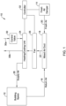
- FIG. 1 is a schematic block diagram showing an illustrative Air Handling Unit (AHU) 10 that may form part of a Heating, Ventilating and Air Conditioning (HVAC) system servicing a building space 12.
- the building space 12 may represent an entire building, for example, or a single floor or zone within a building.
- the AHU 10 includes a fresh air intake damper 14 for admitting a fresh air ventilation flow from outside of the building.
- the AHU 10 includes a return air duct 16 for receiving return air from the building space 12.
- the AHU 10 includes a mixed air duct 18 for mixing a fresh air ventilation air flow 20 from the fresh air intake damper 14 and return air from the return air duct 16 and provides a mixed air flow 22.
- the mixed air flow 22 flows to a heating and/or cooling unit 24.
- a fan 26 may be disposed between the mixed air duct 18 and the heating and/or cooling unit 24.
- the heating and/or cooling unit 24 may be disposed between the mixed air duct 18 and the fan 26.
- the fan 26 provides a motive force to move the return air within the return air duct 16 and the fresh air ventilation air flow 20.
- the fan 26 also provides a motive force to move the supply air flow 28.
- the fan 26 also provides a motive force to move the mixed air flow 22.
- the heated or cooled air exiting the heating and/or cooling unit 24 represents a supply air flow 28 that is provided to the building space 12.
- the AHU 10 may include one fan 26, or may include two or more fans 26 that may be distributed within the AHU 10.
- the AHU 10 includes a control valve 30 that is configured to control the flow of a heating or cooling fluid into the heating and/or cooling unit 24, including an inlet flow 30a and an outlet flow 30b.
- the AHU 10 has a load capacity that provides an indication of a maximum amount of heat that the AHU 10 is able to transfer between a heating or cooling fluid and air being blown through the AHU 10.
- a controller 32 is operatively coupled to the fresh air intake damper 14, the heating and/or cooling unit 24 and the fan 26.
- the controller 32 is configured to determine a current load on the AHU 10 that is used to maintain one or more comfort conditions in the building space 12 and to determine a remaining load capacity of the AHU 10.
- the remaining load capacity is the load capacity of the AHU 10 that is currently not being used, and more particularly, not being used to maintain the one or more comfort conditions in the building space 12. From this, the controller 32 is configured to determine a maximum additional fresh air ventilation air flow that could be admitted and conditioned by the AHU 10 using the remaining load capacity of the AHU 10 such that the AHU 10 could still maintain the one or more comfort conditions in the building space 12.
- the controller 32 is configured to determine a fresh air intake damper position for the fresh air intake damper 14 that increases the fresh air ventilation air flow 20 through the fresh air intake damper 14 by a fraction of the maximum additional fresh air ventilation air flow. The fraction is based at least in part on one or more of a temperature factor and an air quality factor. The controller 32 is configured to set the fresh air intake damper 14 to the determined fresh air intake damper position.
- the fraction may be based at least in part upon a temperature factor, wherein the temperature factor is dependent on a temperature difference between an outside air temperature, representative of a temperature of the fresh air ventilation air flow 20, and an inside air temperature, representative of a temperature of the return air flowing through the return air duct 16.
- the fraction may be based at least in part upon an air quality factor, wherein the air quality factor is dependent on an air quality parameter that is representative of a measure of air quality in the building space 12.
- the fraction may be set to a first weighted sum of the temperature factor and the air quality factor using first weights when the temperature factor and/or the air quality factor meet one or more first predefined conditions and the fraction may be set to a second weighted sum of the temperature factor and the air quality factor using second weights when the temperature factor and/or the air quality factor meet one or more second predefined conditions, wherein at least one of the second weights is different from at least one of the first weights.
- the air quality factor may be dependent on an urgency factor and a favorability factor, where the urgency factor may be dependent on a value of the air quality parameter along a predetermined air quality parameter value range, and the favorability factor may be dependent on a comparison between the air quality parameter that is representative of the measure of air quality in the building space and an air quality parameter that is representative of a measure of air quality outside of the building.
- the air quality factor may be dependent on the urgency factor multiplied by the favorability factor, where the favorability factor may be set to zero when the air quality parameter that is representative of the measure of air quality outside of the building is worse than the air quality parameter that is representative of the measure of air quality in the building space and the favorability factor may be set to one when the air quality parameter that is representative of the measure air quality outside of the building is better than the air quality parameter that is representative of the measure of air quality in the building space 12.
- air quality factors factor CO 2 , factor PM 2.5 , factor TVOC are calculated for each air quality contaminate CO 2 , PM 2.5 and TVOC, respectively, and the air quality factor aq may be the maximum of the air quality factors factor CO 2 , factor PM 2.5 , factor TVOC
- the urgency factor ⁇ CO 2 , ⁇ PM 2.5 and ⁇ TVOC may be determined as shown and described with respect to Figure 2 .
- the temperature factor may be determined as follows:
- factor temp ⁇ 0.0 , diff ⁇ 20.0 ° F OA is too hot expensive for cooling 1.0 , ⁇ 15 ° F ⁇ diff ⁇ 0 ° F OA is very favorable ; free cooling 0.0 , diff ⁇ ⁇ 15 ° F OA is too cold for zone comfort 1 ⁇ diff ⁇ 0 ° F 20 ° F ⁇ 0 ° F , 0 ° F ⁇ diff ⁇ 20 ° F OA needs to cooled by AHU for zone comfort
- Figure 2 is a schematic view of relationships between air quality parameters and corresponding urgency factors ⁇ CO 2 , ⁇ PM 2.5 and ⁇ TVOC .
- Figure 2 includes a graphical representation 34 that shows numerical values for the urgency factor ⁇ CO 2 corresponding to various CO 2 concentrations. In the example shown, if the CO 2 concentration is below 700 ppm (parts per million), the urgency factor ⁇ CO 2 is set equal to 0.2. If the CO 2 concentration is between 700 ppm and 725 ppm, the urgency factor ⁇ CO 2 is set equal to 0.3, for example. If the CO 2 concentration is between 775 ppm and 787.5 ppm, the urgency factor ⁇ CO 2 is set equal to 0.9. If the CO 2 concentration is above 787.5 ppm, or above 800 ppm (which is the CO 2 threshold), the urgency factor ⁇ CO 2 is set equal to 1.0.
- Figure 2 also includes a graphical representation 36 that shows numerical values for the urgency factor ⁇ PM 2 . 5 corresponding to various PM 2.5 (particulate matter) concentrations.
- the urgency factor ⁇ PM 2.5 is set equal to 0.2. If the PM 2.5 concentration is between 20.0 ug/m 3 and 21.0 ug/m 3 , the urgency factor ⁇ PM 2.5 is set equal to 0.3. If the PM 2.5 concentration is between 23.0 ug/m 3 and 23.5 ug/m 3 , the urgency factor ⁇ PM 2.5 is set equal to 0.9. If the PM 2.5 concentration is between 23.5 ug/m 3 and 24.0 ug/m 3 , or above 24.0 ug/m 3 (the PM 2.5 threshold), the urgency factor ⁇ PM 2.5 is set equal to 1.0.
- Figure 2 also includes a graphical representation 38 that shows numerical values for the urgency factor ⁇ TVOC corresponding to various TVOC (total volatile organic compounds) concentrations.
- the urgency factor ⁇ TVOC is set equal to 0.2.
- the urgency factor ⁇ TVOC is set equal to 0.3.
- the urgency factor ⁇ TVOC is set equal to 0.9.
- the urgency factor ⁇ TVOC is set equal to 1.0.
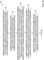
- FIG. 3 is a flow diagram showing an illustrative method 40 for controlling a fresh air intake of an Air Handling Unit (AHU) (such as the AHU 10) of an HVAC (Heating, Ventilating and Air Conditioning) system servicing a building space (such as the building space 12) of a building.
- AHU Air Handling Unit
- HVAC Heating, Ventilating and Air Conditioning
- the AHU includes a fresh air intake damper (such as the fresh air intake damper 14) for admitting a fresh air ventilation air flow (such as the fresh air ventilation air flow 20), a return air duct (such as the return air duct 16) for receiving return air from the building space, a mixed air duct (such as the mixed air duct 22) for mixing the fresh air ventilation air flow from the fresh air intake damper and return air from the return air duct and providing a mixed air flow to a heating and/or cooling unit (such as the heating and/or cooling unit 24) of the AHU which supplies a supply air flow to the building space.
- the AHU also includes a fan (such as the fan 26) for providing a motive force to move the return air, the fresh air ventilation air flow, the mixed air flow and the supply air flow through the AHU.
- the AHU also has a load capacity.
- the illustrative method includes determining a current load on the AHU that is used to maintain one or more comfort conditions in the building space, as indicated at block 42.
- a remaining load capacity of the AHU is determined, wherein the remaining load capacity is the load capacity that is currently not being used, and more particularly, not being used to maintain the one or more comfort conditions in the building space, as indicated at block 44.
- a maximum additional fresh air ventilation air flow is determined that could be admitted and conditioned using the remaining load capacity of the AHU such that the AHU could still maintain the one or more comfort conditions in the building space, as indicated at block 46.
- a fresh air intake damper position is determined for the fresh air intake damper that increases the fresh air ventilation air flow through the fresh air intake damper by a fraction of the maximum additional fresh air ventilation air flow, wherein the fraction is based at least in part on one or more of a temperature factor and an air quality factor, as indicated at block 48.
- the fresh air intake damper is set to the determined fresh air intake damper position, as indicated at block 50.
- the fraction may be based at least in part on a temperature factor, wherein the temperature factor is dependent on a temperature difference between an outside air temperature, representative of a temperature of the fresh air ventilation air flow, and an inside air temperature, representative of a temperature of the return air.
- the temperature factor may be set to zero when the temperature difference is outside of a first predetermined temperature difference range and the temperature factor may be set to one when the temperature difference is within a second predetermined temperature difference range.
- the temperature factor may be scaled between zero and one based at least in part on the temperature difference when the temperature difference is within a third predetermined temperature difference range.
- the fraction may be based at least in part on an air quality factor, wherein the air quality factor is dependent on an air quality parameter that is representative of a measure of air quality in the building space.
- the air quality factor may be dependent on an urgency factor and a favorability factor, where the urgency factor may be dependent on a value of the air quality parameter along a predetermined air quality parameter value range (see Figure 2 ) and the favorability factor may be dependent on a comparison between the air quality parameter that is representative of the measure of air quality in the building space with an air quality parameter that is representative of a measure of air quality outside of the building.
- the air quality factor is dependent on the urgency factor multiplied by the favorability factor, where the favorability factor may be set to zero when the air quality parameter that is representative of the measure of air quality outside of the building is worse than the air quality parameter that is representative of the measure of air quality in the building space and the favorability factor may be set to one when the air quality parameter that is representative of the measure air quality outside of the building is better than the air quality parameter that is representative of the measure of air quality in the building space.
- the fraction may be based at least in part on the temperature factor and the air quality factor, where the temperature factor may be dependent on a temperature difference between an outside air temperature, representative of a temperature of the fresh air ventilation air flow, and an inside air temperature, representative of a temperature of the return air.
- the air quality factor may be dependent on an air quality parameter that is representative of a measure of air quality in the building space.
- the fraction may be set to a first weighted sum of the temperature factor and the air quality factor using first weights when the temperature factor and/or the air quality factor meet one or more first predefined conditions and the fraction may be set to a second weighted sum of the temperature factor and the air quality factor using second weights when the temperature factor and/or the air quality factor meet one or more second predefined conditions, wherein at least one of the second weights is different from at least one of the first weights.
- the air quality factor may be a maximum of a plurality of individual air quality factors, wherein each of the plurality of individual air quality factors relates to a different one of a plurality of air quality parameters.
- the plurality of air quality parameters may include two or more of CO 2 , PM2.5 and TVOC.
- the fraction may be based at least in part on two or more of a temperature factor, an air quality factor and a humidity factor.
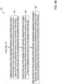
- FIG 4 is a flow diagram showing an illustrative method 52 for controlling a fresh air intake of an Air Handling Unit (AHU) (such as the AHU 10) of an HVAC (Heating, Ventilating and Air Conditioning) system servicing a building space (such as the building space 12) of a building.
- AHU Air Handling Unit
- HVAC Heating, Ventilating and Air Conditioning
- the illustrative method 52 includes estimating a minimum volume of fresh air that will need to be admitted by the AHU to maintain a predetermined air quality parameter below a threshold level in the building space over a predetermined time period into the future, as indicated at block 54.
- One or more outdoor conditions and one or more indoor conditions including temperature and air quality conditions are forecasted over the predetermined time period into the future, as indicated at block 56.
- determining for each of a plurality of time intervals over the predetermined time period a dilution factor that represents an estimated change in the predetermined air quality parameter in response to replacing a predetermined fraction of the air in the building space is determined, as shown at block 60.
- a cost/benefit factor that represents a ratio of the dilution factor and the energy factor is determined, as shown at block 60.
- a portion of the estimated minimum volume of fresh air is assigned to each of the plurality of time intervals (e.g. each hour) of the predetermined time period (e.g. 24 hours) based at least in part on the cost/benefit factors so as to minimize a total energy consumption of the AHU over the predetermined time period (e.g. 24 hours) into the future, as shown at 64.
- the method includes, during a first one of the plurality of time intervals (e.g. during the first hour), setting the fresh air intake of the Air Handling Unit (AHU) to admit the portion of the minimum volume of fresh air assigned to the first one of the plurality of time intervals, as shown at 66.
- AHU Air Handling Unit
- the estimating, forecasting, determining, assigning and setting steps are repeated for the predetermined time period (e.g. 24 hours + 1 Hour) but now starting at the end of the first one of the plurality of time intervals, taking into consideration the actual volume of fresh air that was able to be achieved during the first one of the plurality of time intervals, as indicated at block 68.
- the AHU may not be able to meet the assigned fresh air intake for a particular time interval (e.g. for a particular hour). As an example, when cooling, the outside air may be too warm to efficiently bring in sufficient fresh air during a particular time interval.
- the indoor space may be unexpectedly empty during a time interval in which occupancy is forecasted.
- the temperature factor, favorability factor, urgency factor or some other operating condition may prevent the AHU from meeting the fresh air intake assigned to that particular interval.
- the AHU may recalculate the fresh air intake for each interval during the next 24 hours in order to compensate for a fresh air intake shortfall during the first time interval.
- the AHU may recalculate the fresh air intake for the next 24 hours in order to compensate for changes in conditions and/or changes in forecasted ventilation needs.
- FIG. 5 is a flow diagram showing an illustrative method 70 that may be implemented prior to changing from a first mode 72 to a second mode 74.
- safety checks are performed, as indicated at block 76.
- supply air temperature violations and coil saturation conditions are monitored.
Landscapes
- Engineering & Computer Science (AREA)
- Chemical & Material Sciences (AREA)
- Combustion & Propulsion (AREA)
- Mechanical Engineering (AREA)
- General Engineering & Computer Science (AREA)
- Physics & Mathematics (AREA)
- Fluid Mechanics (AREA)
- Air Conditioning Control Device (AREA)
Abstract
A current load on the AHU used to maintain one or more comfort conditions in the building space is determined, along with a remaining load capacity. A maximum additional fresh air ventilation air flow that could be admitted and conditioned using the remaining load capacity of the AHU such that the AHU could still maintain the one or more comfort conditions in the building space is determined. A fresh air intake damper position for the fresh air intake damper that increases the fresh air ventilation air flow through the fresh air intake damper by a fraction of the maximum additional fresh air ventilation air flow is determined. The fraction may be based at least in part on one or more of a temperature factor and an air quality factor. The fresh air intake damper is set to the determined fresh air intake damper position.
Description
- The present disclosure relates to methods and systems for operating a Heating, Ventilating and Air Conditioning (HVAC) system.
- HVAC systems provide conditioned air for heating and cooling the interior of a building. Some HVAC systems also can provide fresh air ventilation into the building while exhausting an equivalent amount of inside air. Such fresh air ventilation is useful in reducing contaminates produced in the building. However, there are often costs involved in conditioning the fresh air before it can be deployed in the building. For example, in the winter, the cold fresh air must typically be heated by the HVAC system, and in some cases, humidity must be added. Likewise, in the summer, the warm fresh air must typically be cooled by the HVAC system, and in some cases, humidity must be removed. Thus, to reduce operating costs, it is often desirable to minimize the ventilation rate while still adequately ventilating the building given the current contaminates or expected contaminates in the building.
- Under some conditions, such as during a pandemic, it may be desirable to prioritize an increased ventilation rate over energy costs to help reduce the spread of pathogens within the building. Under these conditions, if the ventilation rate is set too high, given the current indoor and outdoor conditions, the HVAC system may lack the heating and/or cooling capacity to adequately condition the incoming fresh air while still maintaining occupant comfort in the building. What would be desirable are methods and systems for operating an HVAC system to provide adequate ventilation while minimizing energy usage and maintaining comfort.
- The present disclosure relates to methods and systems for operating a Heating, Ventilating and Air Conditioning (HVAC) system. An example may be found in a method for controlling a fresh air intake of an Air Handling Unit (AHU) of an HVAC (Heating, Ventilating and Air Conditioning) system servicing a building space of a building. The AHU includes a fresh air intake damper for admitting a fresh air ventilation air flow, a return air duct for receiving return air from the building space, and a mixed air duct for mixing the fresh air ventilation air flow from the fresh air intake damper and return air from the return air duct and providing a mixed air flow to a heating and/or cooling unit of the AHU which supplies a supply air flow to the building space. In this example, the AHU also includes a fan for providing a motive force to move the return air, the fresh air ventilation air flow, the mixed air flow and the supply air flow through the AHU. The AHU also has a load capacity. The illustrative method includes determining a current load on the AHU that is used to maintain one or more comfort conditions in the building space and determining a remaining load capacity of the AHU, wherein the remaining load capacity is the load capacity that is currently not being used to maintain the one or more comfort conditions in the building space. The illustrative method includes determining a maximum additional fresh air ventilation air flow that could be admitted and conditioned using the remaining load capacity of the AHU such that the AHU could still maintain the one or more comfort conditions in the building space. The illustrative method includes determining a fresh air intake damper position for the fresh air intake damper that increases the fresh air ventilation air flow through the fresh air intake damper by a fraction of the maximum additional fresh air ventilation air flow, wherein the fraction is based at least in part on one or more of a temperature factor and an air quality factor. The fraction may be between 0 and 1. The illustrative method includes setting the fresh air intake damper to the determined fresh air intake damper position.
- Another example may be found in an Air Handling Unit (AHU) for servicing a building space of a building. The illustrative AHU includes a heating and/or cooling unit, a fresh air intake damper for admitting a fresh air ventilation air flow, a return air duct for receiving return air from the building space, and a mixed air duct for mixing the fresh air ventilation air flow from the fresh air intake damper and return air from the return air duct and providing a mixed air flow to the heating and/or cooling unit which supplies a supply air flow to the building space. The illustrative AHU includes a fan for providing a motive force to move the return air, the fresh air ventilation air flow, the mixed air flow and the supply air flow through the AHU. The AHU has a load capacity. The AHU includes a controller that is configured to determine a current load on the AHU that is used to maintain one or more comfort conditions in the building space and to determine a remaining load capacity of the AHU, wherein the remaining load capacity is the load capacity that is currently not being used to maintain the one or more comfort conditions in the building space. The controller is configured to determine a maximum additional fresh air ventilation air flow that could be admitted and conditioned using the remaining load capacity of the AHU such that the AHU could still maintain the one or more comfort conditions in the building space. The controller also is configured to determine a fresh air intake damper position for the fresh air intake damper that increases the fresh air ventilation air flow through the fresh air intake damper by a fraction of the maximum additional fresh air ventilation air flow, wherein the fraction is based at least in part on one or more of a temperature factor and an air quality factor. The controller is configured to set the fresh air intake damper to the determined fresh air intake damper position.
- Another example may be found in a method for controlling a fresh air intake of an Air Handling Unit (AHU) of an HVAC (Heating, Ventilating and Air Conditioning) system servicing a building space of a building. The illustrative method includes estimating a minimum volume of fresh air that will need to be admitted by the AHU to maintain a predetermined air quality parameter below a threshold level in the building space over a predetermined time period into the future. The illustrative method includes forecasting one or more outdoor conditions and one or more indoor conditions including temperature and air quality conditions over the predetermined time period into the future. Based on the forecasted one or more outdoor conditions and one or more indoor conditions, determining for each of a plurality of time intervals over the predetermined time period a dilution factor that represents an estimated change in the predetermined air quality parameter in response to replacing a predetermined fraction of the air in the building space, an energy factor that represents an estimated thermal energy required to condition the predetermined fraction of the air in the building space, and a cost/benefit factor that represents a ratio of the dilution factor and the energy factor. The illustrative method includes assigning a portion of the estimated minimum volume of fresh air to each of the plurality of time intervals of the predetermined time period based at least in part on the cost/benefit factors so as to minimize a total energy consumption of the AHU over the predetermined time period into the future. The method includes, during a first one of the plurality of time intervals, setting the fresh air intake of the Air Handling Unit (AHU) to admit the portion of the minimum volume of fresh air assigned to the first one of the plurality of time intervals.
- The preceding summary is provided to facilitate an understanding of some of the innovative features unique to the present disclosure and is not intended to be a full description. A full appreciation of the disclosure can be gained by taking the entire specification, claims, figures, and abstract as a whole.
- The disclosure may be more completely understood in consideration of the following description of various examples in connection with the accompanying drawings, in which:
-
Figure 1 is a schematic block diagram showing an illustrative Air Handling Unit (AHU) that forms part of a Heating, Ventilating and Air Conditioning (HVAC) system servicing a building space; -
Figure 2 is a schematic view of relationships between air quality parameters and corresponding urgency factors; -
Figure 3 is a flow diagram showing an illustrative method for controlling a fresh air intake of an AHU; -
Figures 4A and4B are flow diagrams that together show an illustrative method for controlling a fresh air intake of an AHU; and -
Figure 5 is a flow diagram showing an illustrative method for performing safety checks when mode transition occurs to ensure that thermal comfort is not compromised. - While the disclosure is amenable to various modifications and alternative forms, specifics thereof have been shown by way of example in the drawings and will be described in detail. It should be understood, however, that the intention is not to limit the disclosure to the particular examples described. On the contrary, the intention is to cover all modifications, equivalents, and alternatives falling within the spirit and scope of the disclosure.
- The following description should be read with reference to the drawings, in which like elements in different drawings are numbered in like fashion. The drawings, which are not necessarily to scale, depict examples that are not intended to limit the scope of the disclosure. Although examples are illustrated for the various elements, those skilled in the art will recognize that many of the examples provided have suitable alternatives that may be utilized.
- All numbers are herein assumed to be modified by the term "about", unless the content clearly dictates otherwise. The recitation of numerical ranges by endpoints includes all numbers subsumed within that range (e.g., 1 to 5 includes 1, 1.5, 2, 2.75, 3, 3.80, 4, and 5).
- As used in this specification and the appended claims, the singular forms "a", "an", and "the" include the plural referents unless the content clearly dictates otherwise. As used in this specification and the appended claims, the term "or" is generally employed in its sense including "and/or" unless the content clearly dictates otherwise.
- It is noted that references in the specification to "an embodiment", "some embodiments", "other embodiments", etc., indicate that the embodiment described may include a particular feature, structure, or characteristic, but every embodiment may not necessarily include the particular feature, structure, or characteristic. Moreover, such phrases are not necessarily referring to the same embodiment. Further, when a particular feature, structure, or characteristic is described in connection with an embodiment, it is contemplated that the feature, structure, or characteristic is described in connection with an embodiment, it is contemplated that the feature, structure, or characteristic may be applied to other embodiments whether or not explicitly described unless clearly stated to the contrary.
-
Figure 1 is a schematic block diagram showing an illustrative Air Handling Unit (AHU) 10 that may form part of a Heating, Ventilating and Air Conditioning (HVAC) system servicing abuilding space 12. Thebuilding space 12 may represent an entire building, for example, or a single floor or zone within a building. The AHU 10 includes a freshair intake damper 14 for admitting a fresh air ventilation flow from outside of the building. The AHU 10 includes areturn air duct 16 for receiving return air from thebuilding space 12. TheAHU 10 includes amixed air duct 18 for mixing a fresh airventilation air flow 20 from the freshair intake damper 14 and return air from thereturn air duct 16 and provides amixed air flow 22. Themixed air flow 22 flows to a heating and/orcooling unit 24. In some instances, as shown, afan 26 may be disposed between themixed air duct 18 and the heating and/orcooling unit 24. In some instances, the heating and/orcooling unit 24 may be disposed between themixed air duct 18 and thefan 26. In either case, thefan 26 provides a motive force to move the return air within thereturn air duct 16 and the fresh airventilation air flow 20. In some instances, thefan 26 also provides a motive force to move thesupply air flow 28. In some instances, thefan 26 also provides a motive force to move themixed air flow 22. The heated or cooled air exiting the heating and/orcooling unit 24 represents asupply air flow 28 that is provided to thebuilding space 12. In some instances, theAHU 10 may include onefan 26, or may include two ormore fans 26 that may be distributed within theAHU 10. TheAHU 10 includes acontrol valve 30 that is configured to control the flow of a heating or cooling fluid into the heating and/orcooling unit 24, including aninlet flow 30a and anoutlet flow 30b. TheAHU 10 has a load capacity that provides an indication of a maximum amount of heat that theAHU 10 is able to transfer between a heating or cooling fluid and air being blown through theAHU 10. - A
controller 32 is operatively coupled to the freshair intake damper 14, the heating and/orcooling unit 24 and thefan 26. Thecontroller 32 is configured to determine a current load on theAHU 10 that is used to maintain one or more comfort conditions in thebuilding space 12 and to determine a remaining load capacity of theAHU 10. The remaining load capacity is the load capacity of theAHU 10 that is currently not being used, and more particularly, not being used to maintain the one or more comfort conditions in thebuilding space 12. From this, thecontroller 32 is configured to determine a maximum additional fresh air ventilation air flow that could be admitted and conditioned by theAHU 10 using the remaining load capacity of theAHU 10 such that theAHU 10 could still maintain the one or more comfort conditions in thebuilding space 12. Thecontroller 32 is configured to determine a fresh air intake damper position for the freshair intake damper 14 that increases the fresh airventilation air flow 20 through the freshair intake damper 14 by a fraction of the maximum additional fresh air ventilation air flow. The fraction is based at least in part on one or more of a temperature factor and an air quality factor. Thecontroller 32 is configured to set the freshair intake damper 14 to the determined fresh air intake damper position. - In some instances, the fraction may be based at least in part upon a temperature factor, wherein the temperature factor is dependent on a temperature difference between an outside air temperature, representative of a temperature of the fresh air
ventilation air flow 20, and an inside air temperature, representative of a temperature of the return air flowing through thereturn air duct 16. Alternatively, or in addition, the fraction may be based at least in part upon an air quality factor, wherein the air quality factor is dependent on an air quality parameter that is representative of a measure of air quality in thebuilding space 12. In some instances, the fraction may be set to a first weighted sum of the temperature factor and the air quality factor using first weights when the temperature factor and/or the air quality factor meet one or more first predefined conditions and the fraction may be set to a second weighted sum of the temperature factor and the air quality factor using second weights when the temperature factor and/or the air quality factor meet one or more second predefined conditions, wherein at least one of the second weights is different from at least one of the first weights. - In some instances, the air quality factor may be dependent on an urgency factor and a favorability factor, where the urgency factor may be dependent on a value of the air quality parameter along a predetermined air quality parameter value range, and the favorability factor may be dependent on a comparison between the air quality parameter that is representative of the measure of air quality in the building space and an air quality parameter that is representative of a measure of air quality outside of the building. In some instances, the air quality factor may be dependent on the urgency factor multiplied by the favorability factor, where the favorability factor may be set to zero when the air quality parameter that is representative of the measure of air quality outside of the building is worse than the air quality parameter that is representative of the measure of air quality in the building space and the favorability factor may be set to one when the air quality parameter that is representative of the measure air quality outside of the building is better than the air quality parameter that is representative of the measure of air quality in the
building space 12. - In some instances, the factor may be given by the equation below:

- factortemp :temperature factor; ε [0, 1]
- factoraq total air quality factor; ε [0, 1]
- factoraq = max (factor CO
2 , factor PM2.5, factorTVOC ). - In some instances, air quality factors factor CO
2 , factor PM2.5, factorTVOC are calculated for each air quality contaminate CO2, PM2.5 and TVOC, respectively, and the air quality factoraq may be the maximum of the air quality factors factor CO2 , factor PM2.5, factorTVOC - In some cases, each of the air quality factors factor CO
2 , factor PM2.5, factorTVOC is defined by a corresponding favorability factor β CO2 , β PM2.5, and βTVOC and a corresponding urgency factor α CO2 , α PM2.5 and αTVOC , such follows:


2 , β PM2.5, and βTVOC may be defined as follows:


- The urgency factor α CO
2 , α PM2.5 and αTVOC may be determined as shown and described with respect toFigure 2 . - In some instances, the temperature factor may be determined as follows:
-

-

-
Figure 2 is a schematic view of relationships between air quality parameters and corresponding urgency factors α CO2 , α PM2.5 and αTVOC .Figure 2 includes agraphical representation 34 that shows numerical values for the urgency factor α CO2 corresponding to various CO2 concentrations. In the example shown, if the CO2 concentration is below 700 ppm (parts per million), the urgency factorα CO2 is set equal to 0.2. If the CO2 concentration is between 700 ppm and 725 ppm, the urgency factor α CO2 is set equal to 0.3, for example. If the CO2 concentration is between 775 ppm and 787.5 ppm, the urgency factor α CO2 is set equal to 0.9. If the CO2 concentration is above 787.5 ppm, or above 800 ppm (which is the CO2 threshold), the urgency factor α CO2 is set equal to 1.0. -
Figure 2 also includes agraphical representation 36 that shows numerical values for the urgency factor α PM2.5 corresponding to various PM2.5 (particulate matter) concentrations. In the example shown, if the PM2.5 concentration is below 20.0 ug/m3 (micrograms per cubic meter), the urgency factor α PM2.5 is set equal to 0.2. If the PM2.5 concentration is between 20.0 ug/m3 and 21.0 ug/m3, the urgency factor α PM2.5 is set equal to 0.3. If the PM2.5 concentration is between 23.0 ug/m3 and 23.5 ug/m3, the urgency factor α PM2.5 is set equal to 0.9. If the PM2.5 concentration is between 23.5 ug/m3 and 24.0 ug/m3, or above 24.0 ug/m3 (the PM2.5 threshold), the urgency factor α PM2.5 is set equal to 1.0. -
Figure 2 also includes agraphical representation 38 that shows numerical values for the urgency factor αTVOC corresponding to various TVOC (total volatile organic compounds) concentrations. In the example shown, if the TVOC concentration is below 0.25 mg/m3 (milligrams per cubic meter), the urgency factor αTVOC is set equal to 0.2. If the TVOC concentration is between 0.25 mg/m3 and 0.30 mg/m3, the urgency factor αTVOC is set equal to 0.3. If the TVOC concentration is between 0.4 mg/m3 and 0.425 mg/m3, the urgency factor αTVOC is set equal to 0.9. If the TVOC concentration is between 0.425 mg/m3 and 0.45 mg/m3, or above 0.45 mg/m3 (the TVOC threshold), the urgency factor αTVOC is set equal to 1.0. These are just examples. In some cases, a facilities manager or the like may program a different relationship between the urgency factors and the various concentration levels, if desired. -
Figure 3 is a flow diagram showing anillustrative method 40 for controlling a fresh air intake of an Air Handling Unit (AHU) (such as the AHU 10) of an HVAC (Heating, Ventilating and Air Conditioning) system servicing a building space (such as the building space 12) of a building. The AHU includes a fresh air intake damper (such as the fresh air intake damper 14) for admitting a fresh air ventilation air flow (such as the fresh air ventilation air flow 20), a return air duct (such as the return air duct 16) for receiving return air from the building space, a mixed air duct (such as the mixed air duct 22) for mixing the fresh air ventilation air flow from the fresh air intake damper and return air from the return air duct and providing a mixed air flow to a heating and/or cooling unit (such as the heating and/or cooling unit 24) of the AHU which supplies a supply air flow to the building space. In this example, the AHU also includes a fan (such as the fan 26) for providing a motive force to move the return air, the fresh air ventilation air flow, the mixed air flow and the supply air flow through the AHU. The AHU also has a load capacity. - The illustrative method includes determining a current load on the AHU that is used to maintain one or more comfort conditions in the building space, as indicated at
block 42. A remaining load capacity of the AHU is determined, wherein the remaining load capacity is the load capacity that is currently not being used, and more particularly, not being used to maintain the one or more comfort conditions in the building space, as indicated atblock 44. A maximum additional fresh air ventilation air flow is determined that could be admitted and conditioned using the remaining load capacity of the AHU such that the AHU could still maintain the one or more comfort conditions in the building space, as indicated atblock 46. A fresh air intake damper position is determined for the fresh air intake damper that increases the fresh air ventilation air flow through the fresh air intake damper by a fraction of the maximum additional fresh air ventilation air flow, wherein the fraction is based at least in part on one or more of a temperature factor and an air quality factor, as indicated atblock 48. The fresh air intake damper is set to the determined fresh air intake damper position, as indicated atblock 50. - In some instances, the fraction may be based at least in part on a temperature factor, wherein the temperature factor is dependent on a temperature difference between an outside air temperature, representative of a temperature of the fresh air ventilation air flow, and an inside air temperature, representative of a temperature of the return air. As an example, the temperature factor may be set to zero when the temperature difference is outside of a first predetermined temperature difference range and the temperature factor may be set to one when the temperature difference is within a second predetermined temperature difference range. In some instances, the temperature factor may be scaled between zero and one based at least in part on the temperature difference when the temperature difference is within a third predetermined temperature difference range.
- In some instances, the fraction may be based at least in part on an air quality factor, wherein the air quality factor is dependent on an air quality parameter that is representative of a measure of air quality in the building space. In some instances, the air quality factor may be dependent on an urgency factor and a favorability factor, where the urgency factor may be dependent on a value of the air quality parameter along a predetermined air quality parameter value range (see
Figure 2 ) and the favorability factor may be dependent on a comparison between the air quality parameter that is representative of the measure of air quality in the building space with an air quality parameter that is representative of a measure of air quality outside of the building. In some instances, the air quality factor is dependent on the urgency factor multiplied by the favorability factor, where the favorability factor may be set to zero when the air quality parameter that is representative of the measure of air quality outside of the building is worse than the air quality parameter that is representative of the measure of air quality in the building space and the favorability factor may be set to one when the air quality parameter that is representative of the measure air quality outside of the building is better than the air quality parameter that is representative of the measure of air quality in the building space. - In some instances, the fraction may be based at least in part on the temperature factor and the air quality factor, where the temperature factor may be dependent on a temperature difference between an outside air temperature, representative of a temperature of the fresh air ventilation air flow, and an inside air temperature, representative of a temperature of the return air. The air quality factor may be dependent on an air quality parameter that is representative of a measure of air quality in the building space.
- In some instances, the fraction may be set to a first weighted sum of the temperature factor and the air quality factor using first weights when the temperature factor and/or the air quality factor meet one or more first predefined conditions and the fraction may be set to a second weighted sum of the temperature factor and the air quality factor using second weights when the temperature factor and/or the air quality factor meet one or more second predefined conditions, wherein at least one of the second weights is different from at least one of the first weights. In some instances, the air quality factor may be a maximum of a plurality of individual air quality factors, wherein each of the plurality of individual air quality factors relates to a different one of a plurality of air quality parameters. As an example, the plurality of air quality parameters may include two or more of CO2, PM2.5 and TVOC. In some instances, the fraction may be based at least in part on two or more of a temperature factor, an air quality factor and a humidity factor.
-
Figure 4 is a flow diagram showing anillustrative method 52 for controlling a fresh air intake of an Air Handling Unit (AHU) (such as the AHU 10) of an HVAC (Heating, Ventilating and Air Conditioning) system servicing a building space (such as the building space 12) of a building. Theillustrative method 52 includes estimating a minimum volume of fresh air that will need to be admitted by the AHU to maintain a predetermined air quality parameter below a threshold level in the building space over a predetermined time period into the future, as indicated atblock 54. One or more outdoor conditions and one or more indoor conditions including temperature and air quality conditions are forecasted over the predetermined time period into the future, as indicated atblock 56. Based on the forecasted one or more outdoor conditions and one or more indoor conditions, determining for each of a plurality of time intervals over the predetermined time period a dilution factor that represents an estimated change in the predetermined air quality parameter in response to replacing a predetermined fraction of the air in the building space is determined, as shown atblock 60. Based on the forecasted one or more outdoor conditions and one or more indoor conditions, a cost/benefit factor that represents a ratio of the dilution factor and the energy factor is determined, as shown atblock 60. - Continuing on
Figure 4B , a portion of the estimated minimum volume of fresh air is assigned to each of the plurality of time intervals (e.g. each hour) of the predetermined time period (e.g. 24 hours) based at least in part on the cost/benefit factors so as to minimize a total energy consumption of the AHU over the predetermined time period (e.g. 24 hours) into the future, as shown at 64. The method includes, during a first one of the plurality of time intervals (e.g. during the first hour), setting the fresh air intake of the Air Handling Unit (AHU) to admit the portion of the minimum volume of fresh air assigned to the first one of the plurality of time intervals, as shown at 66. In some instances, after the first one of the plurality of time intervals (e.g. after hour 1), the estimating, forecasting, determining, assigning and setting steps are repeated for the predetermined time period (e.g. 24 hours + 1 Hour) but now starting at the end of the first one of the plurality of time intervals, taking into consideration the actual volume of fresh air that was able to be achieved during the first one of the plurality of time intervals, as indicated atblock 68. In some instances, for various reasons, the AHU may not be able to meet the assigned fresh air intake for a particular time interval (e.g. for a particular hour). As an example, when cooling, the outside air may be too warm to efficiently bring in sufficient fresh air during a particular time interval. As another example, the indoor space may be unexpectedly empty during a time interval in which occupancy is forecasted. In another example, during operation of the AHU during a particular one of the plurality of time intervals, the temperature factor, favorability factor, urgency factor or some other operating condition may prevent the AHU from meeting the fresh air intake assigned to that particular interval. As such, and in some instances, at the end of the first time interval, the AHU may recalculate the fresh air intake for each interval during the next 24 hours in order to compensate for a fresh air intake shortfall during the first time interval. Alternatively, or in addition, the AHU may recalculate the fresh air intake for the next 24 hours in order to compensate for changes in conditions and/or changes in forecasted ventilation needs. - In some instances, whenever a mode transition is indicated, such as transitioning from a comfort mode to an energy mode, or from a comfort mode to a health mode, or from an energy mode to a health mode, for example, checks may be performed to ensure that thermal comfort is not compromised. An example may be if the mode transition will mean an increase in fresh air being brought into the building, but the AHU is not currently able to heat or cool that increased fresh air flow sufficiently to maintain a temperature setpoint.
Figure 5 is a flow diagram showing anillustrative method 70 that may be implemented prior to changing from afirst mode 72 to asecond mode 74. As part of the mode transition, safety checks are performed, as indicated atblock 76. As indicated atblock 78, supply air temperature violations and coil saturation conditions are monitored. If there are no thermal comfort and IAQ violation conditions, as indicated at 80, control passes to block 82 and the mode transition is completed. However, if there are thermal comfort or IAQ violation conditions, as indicated at 84, control passes to block 86 and the mode transition is not completed. - Having thus described several illustrative embodiments of the present disclosure, those of skill in the art will readily appreciate that yet other embodiments may be made and used within the scope of the claims hereto attached. It will be understood, however, that this disclosure is, in many respects, only illustrative. Changes may be made in details, particularly in matters of shape, size, arrangement of parts, and exclusion and order of steps, without exceeding the scope of the disclosure. The disclosure's scope is, of course, defined in the language in which the appended claims are expressed.
Claims (15)
- A method for controlling a fresh air intake of an Air Handling Unit (AHU) of an HVAC (Heating, Ventilating and Air Conditioning) system servicing a building space of a building, the AHU including a fresh air intake damper for admitting a fresh air ventilation air flow, a return air duct for receiving return air from the building space, a mixed air duct for mixing the fresh air ventilation air flow from the fresh air intake damper and return air from the return air duct and providing a mixed air flow to a heating and/or cooling unit of the AHU which supplies a supply air flow to the building space, the AHU including a fan for providing a motive force to move the return air, the fresh air ventilation air flow, the mixed air flow and the supply air flow through the AHU, the AHU having a load capacity, the method comprising:determining a current load on the AHU that is used to maintain one or more comfort conditions in the building space;determining a remaining load capacity of the AHU, wherein the remaining load capacity is the load capacity that is currently not being used to maintain the one or more comfort conditions in the building space;determining a maximum additional fresh air ventilation air flow that could be admitted and conditioned using the remaining load capacity of the AHU such that the AHU could still maintain the one or more comfort conditions in the building space;determining a fresh air intake damper position for the fresh air intake damper that increases the fresh air ventilation air flow through the fresh air intake damper by a fraction of the maximum additional fresh air ventilation air flow, wherein the fraction is based at least in part on one or more of a temperature factor and an air quality factor; andsetting the fresh air intake damper to the determined fresh air intake damper position.
- The method of claim 1, wherein the fraction is based at least in part on the temperature factor, wherein the temperature factor is dependent on a temperature difference between an outside air temperature, representative of a temperature of the fresh air ventilation air flow, and an inside air temperature, representative of a temperature of the return air.
- The method of claim 2, wherein the temperature factor is set to zero when the temperature difference is outside of a first predetermined temperature difference range.
- The method of claim 2, wherein the temperature factor is set to one when the temperature difference is within a second predetermined temperature difference range.
- The method of claim 2, wherein the temperature factor is scaled between zero and one based at least in part on the temperature difference when the temperature difference is within a third predetermined temperature difference range.
- The method of claim 1, wherein the fraction is based at least in part on an air quality factor, wherein the air quality factor is dependent on an air quality parameter that is representative of a measure of air quality in the building space.
- The method of claim 6, wherein the air quality factor is dependent on an urgency factor and a favorability factor, wherein:the urgency factor is dependent on a value of the air quality parameter along a predetermined air quality parameter value range; andthe favorability factor is dependent on a comparison between the air quality parameter that is representative of the measure of air quality in the building space with an air quality parameter that is representative of a measure of air quality outside of the building.
- The method of claim 7, wherein the air quality factor is dependent on the urgency factor multiplied by the favorability factor, wherein:the favorability factor is set to zero when the air quality parameter that is representative of the measure of air quality outside of the building is worse than the air quality parameter that is representative of the measure of air quality in the building space; andthe favorability factor is set to one when the air quality parameter that is representative of the measure air quality outside of the building is better than the air quality parameter that is representative of the measure of air quality in the building space.
- The method of claim 1, wherein the fraction is based at least in part on the temperature factor and the air quality factor, wherein:the temperature factor is dependent on a temperature difference between an outside air temperature, representative of a temperature of the fresh air ventilation air flow, and an inside air temperature, representative of a temperature of the return air; andthe air quality factor is dependent on an air quality parameter that is representative of a measure of air quality in the building space.
- The method of claim 9, wherein:the fraction is set to a first weighted sum of the temperature factor and the air quality factor using first weights when the temperature factor and/or the air quality factor meet one or more first predefined conditions; andthe fraction is set to a second weighted sum of the temperature factor and the air quality factor using second weights when the temperature factor and/or the air quality factor meet one or more second predefined conditions, wherein at least one of the second weights is different from at least one of the first weights.
- The method of claim 1, wherein the air quality factor is a maximum of a plurality of individual air quality factors, wherein each of the plurality of individual air quality factors relates to a different one of a plurality of air quality parameters.
- The method of claim 11, wherein the plurality of air quality parameters include two or more of CO2, PM2.5 and TVOC.
- The method of claim 1, wherein the fraction is based at least in part on two or more of a temperature factor, an air quality factor and a humidity factor.
- An Air Handling Unit (AHU) for servicing a building space of a building, the AHU comprising:a heating and/or cooling unit;a fresh air intake damper for admitting a fresh air ventilation air flow;a return air duct for receiving return air from the building space;a mixed air duct for mixing the fresh air ventilation air flow from the fresh air intake damper and return air from the return air duct and providing a mixed air flow to the heating and/or cooling unit which supplies a supply air flow to the building space;a fan for providing a motive force to move the return air, the fresh air ventilation air flow, the mixed air flow and the supply air flow through the AHU;the AHU having a load capacity;a controller, wherein the controller is configured to:determine a current load on the AHU that is used to maintain one or more comfort conditions in the building space;determine a remaining load capacity of the AHU, wherein the remaining load capacity is the load capacity that is currently not being used to maintain the one or more comfort conditions in the building space;determine a maximum additional fresh air ventilation air flow that could be admitted and conditioned using the remaining load capacity of the AHU such that the AHU could still maintain the one or more comfort conditions in the building space;determine a fresh air intake damper position for the fresh air intake damper that increases the fresh air ventilation air flow through the fresh air intake damper by a fraction of the maximum additional fresh air ventilation air flow, wherein the fraction is based at least in part on one or more of a temperature factor and an air quality factor; andsetting the fresh air intake damper to the determined fresh air intake damper position.
- The AHU of claim 14, wherein the fraction is based at least in part on:the temperature factor, wherein the temperature factor is dependent on a temperature difference between an outside air temperature, representative of a temperature of the fresh air ventilation air flow, and an inside air temperature, representative of a temperature of the return air; andthe air quality factor, wherein the air quality factor is dependent on an air quality parameter that is representative of a measure of air quality in the building space.
Applications Claiming Priority (1)
| Application Number | Priority Date | Filing Date | Title |
|---|---|---|---|
| IN202311036537 | 2023-05-26 |
Publications (1)
| Publication Number | Publication Date |
|---|---|
| EP4467887A1 true EP4467887A1 (en) | 2024-11-27 |
Family
ID=91247008
Family Applications (1)
| Application Number | Title | Priority Date | Filing Date |
|---|---|---|---|
| EP24177731.7A Pending EP4467887A1 (en) | 2023-05-26 | 2024-05-23 | Method and system for controlling fresh air ventilation of an air handling unit of an hvac system |
Country Status (2)
| Country | Link |
|---|---|
| US (1) | US20240392999A1 (en) |
| EP (1) | EP4467887A1 (en) |
Citations (5)
| Publication number | Priority date | Publication date | Assignee | Title |
|---|---|---|---|---|
| US6415617B1 (en) * | 2001-01-10 | 2002-07-09 | Johnson Controls Technology Company | Model based economizer control of an air handling unit |
| US6698219B2 (en) * | 2001-11-30 | 2004-03-02 | National University Of Singapore | Energy-efficient variable-air-volume (VAV) system with zonal ventilation control |
| US20220178574A1 (en) * | 2020-12-07 | 2022-06-09 | Syracuse University | System for minimizing indoor infection risk and maximizing energy savings |
| US20220221184A1 (en) * | 2021-01-14 | 2022-07-14 | Honeywell International Inc. | Dynamic ventilation control for a building |
| US20220282886A1 (en) * | 2021-03-03 | 2022-09-08 | Siemens Industry, Inc. | System and method for high ventilation of outdoor air |
-
2024
- 2024-05-20 US US18/669,117 patent/US20240392999A1/en active Pending
- 2024-05-23 EP EP24177731.7A patent/EP4467887A1/en active Pending
Patent Citations (5)
| Publication number | Priority date | Publication date | Assignee | Title |
|---|---|---|---|---|
| US6415617B1 (en) * | 2001-01-10 | 2002-07-09 | Johnson Controls Technology Company | Model based economizer control of an air handling unit |
| US6698219B2 (en) * | 2001-11-30 | 2004-03-02 | National University Of Singapore | Energy-efficient variable-air-volume (VAV) system with zonal ventilation control |
| US20220178574A1 (en) * | 2020-12-07 | 2022-06-09 | Syracuse University | System for minimizing indoor infection risk and maximizing energy savings |
| US20220221184A1 (en) * | 2021-01-14 | 2022-07-14 | Honeywell International Inc. | Dynamic ventilation control for a building |
| US20220282886A1 (en) * | 2021-03-03 | 2022-09-08 | Siemens Industry, Inc. | System and method for high ventilation of outdoor air |
Also Published As
| Publication number | Publication date |
|---|---|
| US20240392999A1 (en) | 2024-11-28 |
Similar Documents
| Publication | Publication Date | Title |
|---|---|---|
| US6916239B2 (en) | Air quality control system based on occupancy | |
| Wang et al. | Multi-zone outdoor air coordination through Wi-Fi probe-based occupancy sensing | |
| US5597354A (en) | Indoor air quality control for constant volume heating, ventilating and air conditioning units | |
| Brooks et al. | Energy-efficient control of under-actuated HVAC zones in commercial buildings | |
| Cho et al. | Minimum airflow reset of single duct VAV terminal boxes | |
| US6919809B2 (en) | Optimization of building ventilation by system and zone level action | |
| US5791408A (en) | Air handling unit including control system that prevents outside air from entering the unit through an exhaust air damper | |
| KR100509332B1 (en) | Iaq control method based on contaminant concentration for various ventilation modes of energy saving, and network-based iaq control system | |
| US6170271B1 (en) | Sizing and control of fresh air dehumidification unit | |
| EP2781851A1 (en) | Air conditioning system and air conditioning control method for server room management | |
| US20060130502A1 (en) | Virtual controller for mixed air low temperature protection of HVAC systems | |
| KR102500304B1 (en) | CO2 control method for variable air volume system | |
| US20240019158A1 (en) | Building system with multi-tiered model based optimization for ventilation and setpoint control | |
| KR100643264B1 (en) | Classification Rule-Based Fault Diagnosis in HVAC Systems | |
| US20230011991A1 (en) | Indoor air quality for variable air volume system | |
| Nassif et al. | Ventilation control strategy using the supply CO2 concentration setpoint | |
| KR102032811B1 (en) | Appratus and method of reducing energy consumption using removed heat capacity of refrigerator | |
| US20240392999A1 (en) | Method and system for controlling fresh air ventilation of an air handling unit of an hvac system | |
| EP3098529B1 (en) | Coordinated control of hvac system using aggregated system demand | |
| EP4484840A1 (en) | System and method to control operation of an hvac system for conditioning indoor air quality | |
| EP4300000A1 (en) | Method for operating an hvac system | |
| EP4299999A1 (en) | Methods and systems for operating an hvac system | |
| JP7611679B2 (en) | Ventilation control device and ventilation control method | |
| EP4464949A1 (en) | Method and system for controlling a fresh air intake of an air handling unit of an hvac system | |
| EP4513098A1 (en) | Methods and systems for controlling an hvac system to identify energy usage under different control strategies |
Legal Events
| Date | Code | Title | Description |
|---|---|---|---|
| PUAI | Public reference made under article 153(3) epc to a published international application that has entered the european phase |
Free format text: ORIGINAL CODE: 0009012 |
|
| STAA | Information on the status of an ep patent application or granted ep patent |
Free format text: STATUS: REQUEST FOR EXAMINATION WAS MADE |
|
| 17P | Request for examination filed |
Effective date: 20240523 |
|
| AK | Designated contracting states |
Kind code of ref document: A1 Designated state(s): AL AT BE BG CH CY CZ DE DK EE ES FI FR GB GR HR HU IE IS IT LI LT LU LV MC ME MK MT NL NO PL PT RO RS SE SI SK SM TR |
|
| STAA | Information on the status of an ep patent application or granted ep patent |
Free format text: STATUS: EXAMINATION IS IN PROGRESS |