EP4467845A1 - Strain wave drive - Google Patents
Strain wave drive Download PDFInfo
- Publication number
- EP4467845A1 EP4467845A1 EP23461598.7A EP23461598A EP4467845A1 EP 4467845 A1 EP4467845 A1 EP 4467845A1 EP 23461598 A EP23461598 A EP 23461598A EP 4467845 A1 EP4467845 A1 EP 4467845A1
- Authority
- EP
- European Patent Office
- Prior art keywords
- flex spline
- teeth
- ring gear
- strain wave
- wave drive
- Prior art date
- Legal status (The legal status is an assumption and is not a legal conclusion. Google has not performed a legal analysis and makes no representation as to the accuracy of the status listed.)
- Pending
Links
Images

Classifications
-
- F—MECHANICAL ENGINEERING; LIGHTING; HEATING; WEAPONS; BLASTING
- F16—ENGINEERING ELEMENTS AND UNITS; GENERAL MEASURES FOR PRODUCING AND MAINTAINING EFFECTIVE FUNCTIONING OF MACHINES OR INSTALLATIONS; THERMAL INSULATION IN GENERAL
- F16H—GEARING
- F16H49/00—Other gearings
- F16H49/001—Wave gearings, e.g. harmonic drive transmissions
-
- B—PERFORMING OPERATIONS; TRANSPORTING
- B64—AIRCRAFT; AVIATION; COSMONAUTICS
- B64C—AEROPLANES; HELICOPTERS
- B64C13/00—Control systems or transmitting systems for actuating flying-control surfaces, lift-increasing flaps, air brakes, or spoilers
- B64C13/24—Transmitting means
- B64C13/26—Transmitting means without power amplification or where power amplification is irrelevant
- B64C13/28—Transmitting means without power amplification or where power amplification is irrelevant mechanical
-
- F—MECHANICAL ENGINEERING; LIGHTING; HEATING; WEAPONS; BLASTING
- F16—ENGINEERING ELEMENTS AND UNITS; GENERAL MEASURES FOR PRODUCING AND MAINTAINING EFFECTIVE FUNCTIONING OF MACHINES OR INSTALLATIONS; THERMAL INSULATION IN GENERAL
- F16H—GEARING
- F16H55/00—Elements with teeth or friction surfaces for conveying motion; Worms, pulleys or sheaves for gearing mechanisms
- F16H55/02—Toothed members; Worms
- F16H55/08—Profiling
- F16H55/0833—Flexible toothed member, e.g. harmonic drive
-
- F—MECHANICAL ENGINEERING; LIGHTING; HEATING; WEAPONS; BLASTING
- F16—ENGINEERING ELEMENTS AND UNITS; GENERAL MEASURES FOR PRODUCING AND MAINTAINING EFFECTIVE FUNCTIONING OF MACHINES OR INSTALLATIONS; THERMAL INSULATION IN GENERAL
- F16H—GEARING
- F16H49/00—Other gearings
- F16H49/001—Wave gearings, e.g. harmonic drive transmissions
- F16H2049/003—Features of the flexsplines therefor
Definitions
- Rotary actuation of devices or surfaces e.g. flight control surfaces in an aircraft, requires high torque drive and so typically requires gearing between the electric motor, which is typically high speed, low torque, and the output shaft of the actuator that drives the surface.
- Conventional involute gears comprising a number of intermeshing toothed wheels to create the required gear ratio, are relatively large and heavy and the higher the required ratio, the more gears and, thus, the greater the size and weight of the overall actuator system.
- strain wave drive or gear A known type of gear mechanism that is particularly compact is the strain wave drive or gear.
- Strain wave gearing also known as a harmonic drive, is used in many drive trains as it is compact and lightweight and can be used to provide a high gear ratio between an input or drive shaft and an output shaft.
- a drive shaft connected to the wave generator, is rotated e.g. by a motor, which causes rotation of the wave generator.
- the bearing conforms to the elliptical shape of the wave generator.
- the flex spline conforms to the shape of the drive shaft and so as the wave generator rotates, the flex spline will only engage with the inner teeth of the outer ring at the major axes of the ellipse.
- the circular spline has a different number of inner teeth to the number of outer teeth of the flex spline. Rotation of the drive shaft thus causes a slower rotation of the output shaft by its engagement with the flex spline.
- the output shaft is connected to the device or surface to be moved by the actuator.
- strain wave drives however, have to be designed with built-in compliance (as discussed below) to ensure correct load distribution and engagement of the teeth. This adds to the costs and complexity of such gears for use in e.g. flight control rotary actuation. There is, therefore, a desire for an improved strain wave drive that retains the benefits of compactness and light weight whilst overcoming problems associated with existing strain wave drives.
- a strain wave drive comprising: an elliptical wave generator shaft rotatable about an axis (X); a flexible flex spline mounted around the wave generator shaft; a ring gear assembly mounted around the flex spline, the ring gear assembly comprising an output ring gear having a circular inner periphery and being sandwiched between two earth ring gears each having a circular inner periphery; wherein the flex spline has a first set of a first number of radially outwardly extending teeth around its outer periphery; and wherein each earth ring gear has the first number of radially inwardly extending teeth to engage with the first set of teeth of the flex spline; and wherein the flex spline has a second set of the first number of radially outwardly extending teeth around its outer periphery wherein the output ring gear has a second number of radially inwardly extending teeth, such that as the wave generator shaft rotate
- strain wave drives essentially consist of three main parts: a wave generator, driven by the motor drive shaft, is an elliptical shaft having bearings arranged around the outer perimeter thereof.
- the wave generator is located within a cylindrical flex spline which is a flexible annular component having radially outwardly extending teeth.
- the flex spline is sufficiently flexible to take up the elliptical shape of the wave generator as the wave generator and its bearings rotate within the flex spline.
- a rigid circular spline is a ring that fits around the flex spline.
- the circular spline has inwardly extending teeth.
- the circular spline is typically fixed e.g. to the actuator housing.
- the wave generator As the wave generator is rotated by the motor, it causes the flex spline to take up the elliptical shape such that the outwardly extending teeth of the flex spline mesh with the inwardly extending teeth of the circular spline at the locations of the major axis of the ellipse.
- the circular spline typically has more teeth than the flex spline such that as the teeth engage, the flex spline is caused to rotate relative to the circular spline at a rate of rotation different to that of the motor.
- an output ring gear is positioned around the flex spline.
- the output ring gear is provided with inner teeth that engage with the teeth of the flex spline.
- the output ring gear is connected with a part or component to be moved by the drive.
- strain wave drives for rotary actuation of flight control surfaces require a right-angled U-shaped or cup-shaped flex spline to provide the flex spline function within the available space envelope and with the required strength and stress resistance.
- the right-angle cup shape adds stiffness and distributes stress through the earthed parts of the system.
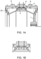
- An example of such a strain wave drive is shown in Figs. 1A and 1B . Because the flex spline is cup-shaped, it has to be formed as two cup parts for manufacturing and assembly purposes, the two cup parts meeting at a join aligned with the output ring gear sandwiched between the earth gears.
- Figure 1A shows a section of the strain wave drive, showing the wave generator 1, rotatable about axis A. Needle bearings 2 are provided around the perimeter of the wave generator 1.
- the flex spline 3 is fitted around the wave generator to engage with the bearings to take up the elliptical shape of the wave generator.
- two flex splines are provided, each formed with a flange 30. Teeth (not shown in this figure) on the outer surface of the flex spline engage, at certain positions of rotation, with inwardly extending teeth (not shown in this figure) of the output ring gear 4.
- the earth gears may be fixed relative to the actuator housing or other fixed component and the flex spline may engage with an output shaft or output ring gear 4 which is caused to rotate with rotation of the point of engagement with the flex spline as the wave generator rotates.
- the output gear rotates according to the gear ratio and may be fixed to a part or surface to be rotated e.g. a flight control surface.
- the split, two-part flex spline forms a conical shape at its interface with the output gear and the earth gears which can cause an uneven interference between the inter-meshing teeth at some positions, i.e. when the flex spline deflects, it engages with the corresponding teeth at an angle. This angle may also vary under changing loads and temperatures.
- the strain wave drive of this disclosure incorporates compliance into the drive by modifying the shape of the bearing rollers and/or the longitudinal profile of the flex spline teeth.
- C represents the curved profile of the bearings.
- the bearings are formed with a barrel shape or a longitudinal convex surface shape as opposed to providing a straight or flat surface interface between the bearing and the flex spline as is conventionally the case.
- the compliance in the shaping of the bearing rollers allows the flex spline to follow the barrel curve in the longitudinal direction.
- the output ring gear 200 has two teeth more that the flex spline 500 and this provides the gear ratio.
- the bearings here needle rollers 600, are fitted around the wave generator 100 on a cage of bearing support rollers 700.
- the bearings 600 rotate with the wave generator 100 and impart the elliptical shape of the wave generator to the flex spline 500.
- the outer sections of the flex spline are secured by the earth gears and, at the major diameter of the ellipse, the middle section of the flex spline is deformed to take up the elliptical shape and its teeth, in that section, mesh with the teeth of the output gear causing it to rotate.
- the curved surface C of the bearings 600, or the profile of the flex spline teeth is, as mentioned above, formed with a curved or barrel profile to provide the required compliance to the flex spline to compensate for coning.
- the contact between the bearings and the flex spline causes the flex spline to adapt to the curved shape C of the bearing rollers.
- the curvature or 'crowning' allows for several degrees of self-alignment of the bearings and flex spline, which adds further compliance to the design.
- the strain wave drive has a compliant design that provides uniform stress distribution loading.
- the bearing/teeth profile may be precision machined. Because the curvature of the bearings/teeth profile results in a reduced edge/point contact, there is reduced drag and wear on the flex spline and a higher load capability.
- the design is simple to manufacture and assemble.
Landscapes
- Engineering & Computer Science (AREA)
- General Engineering & Computer Science (AREA)
- Mechanical Engineering (AREA)
- Automation & Control Theory (AREA)
- Aviation & Aerospace Engineering (AREA)
- Retarders (AREA)
Abstract
A strain wave drive comprising: an elliptical wave generator shaft (100) rotatable about an axis (X); a flexible flex spline (500) mounted around the wave generator shaft; a ring gear assembly mounted around the flex spline, the ring gear assembly comprising an output ring gear (200) having a circular inner periphery and being sandwiched between two earth ring gears (300, 400) each having a circular inner periphery; wherein the flex spline has a first set of a first number of radially outwardly extending teeth around its outer periphery; and wherein each earth ring gear has the first number of radially inwardly extending teeth to engage with the first set of teeth of the flex spline; and wherein the flex spline has a second set of the first number of radially outwardly extending teeth around its outer periphery wherein the output ring gear has a second number of radially inwardly extending teeth, such that as the wave generator shaft rotates, it causes the flex spline to take up the elliptical form of the wave generator shaft and the teeth of the flex spline engage with second set of teeth of the output ring gear at the major diameter of the ellipse, causing the output ring gear to rotate; and wherein the wave generator shaft is provided with a radially outer surface defining the elliptical shape and arranged to engage with an inner surface of the flex spline; the strain wave drive further comprising roller bearing supports provided between the cam surface and the flex spline, and wherein the roller bearing supports and/or the teeth of the flex spline define a longitudinal barrel profile, are formed with a longitudinal barrel shape to define a convex curved surface at the interface between the bearings and the flex spline.
Description
- The present disclosure relates to a strain wave drive particularly a strain wave drive for rotary actuation of flight control surfaces of an aircraft.
- Rotary actuation of devices or surfaces e.g. flight control surfaces in an aircraft, requires high torque drive and so typically requires gearing between the electric motor, which is typically high speed, low torque, and the output shaft of the actuator that drives the surface. Conventional involute gears, comprising a number of intermeshing toothed wheels to create the required gear ratio, are relatively large and heavy and the higher the required ratio, the more gears and, thus, the greater the size and weight of the overall actuator system.
- In aircraft in particular, and also in other applications, there is a need to minimise the size and weight of components and there is a desire to provide a gear or drive that can provide the required torque ratio using a smaller, lighter, more compact arrangement.
- A known type of gear mechanism that is particularly compact is the strain wave drive or gear. Strain wave gearing, also known as a harmonic drive, is used in many drive trains as it is compact and lightweight and can be used to provide a high gear ratio between an input or drive shaft and an output shaft. These properties make strain wave gearing suited to use in aircraft and other vehicles where space is limited and weight of components should be minimised, whilst maintaining reliability and performance.
- A strain wave gear system includes a wave generator which is in the form of an elliptical shaft and a compliant ball bearing in which the elliptical shaft rotates. A flexible toothed ring (a flex spline) is mounted about the wave generator and engages, and conforms to the shape of, the output shaft. A fixed outer ring, or circular spline is provided around the flex spline and has inner teeth that engage with the outer teeth of the flex spline but, due to the elliptical shape of the wave generator, the flex spline only engages with the teeth of the outer ring at the major diameter of the wave generator.
- In operation, a drive shaft, connected to the wave generator, is rotated e.g. by a motor, which causes rotation of the wave generator. The bearing conforms to the elliptical shape of the wave generator. The flex spline conforms to the shape of the drive shaft and so as the wave generator rotates, the flex spline will only engage with the inner teeth of the outer ring at the major axes of the ellipse. The circular spline has a different number of inner teeth to the number of outer teeth of the flex spline. Rotation of the drive shaft thus causes a slower rotation of the output shaft by its engagement with the flex spline. The output shaft is connected to the device or surface to be moved by the actuator.
- Known strain wave drives, however, have to be designed with built-in compliance (as discussed below) to ensure correct load distribution and engagement of the teeth. This adds to the costs and complexity of such gears for use in e.g. flight control rotary actuation. There is, therefore, a desire for an improved strain wave drive that retains the benefits of compactness and light weight whilst overcoming problems associated with existing strain wave drives.
- According to the disclosure, there is provided a strain wave drive comprising: an elliptical wave generator shaft rotatable about an axis (X);a flexible flex spline mounted around the wave generator shaft; a ring gear assembly mounted around the flex spline, the ring gear assembly comprising an output ring gear having a circular inner periphery and being sandwiched between two earth ring gears each having a circular inner periphery; wherein the flex spline has a first set of a first number of radially outwardly extending teeth around its outer periphery; and wherein each earth ring gear has the first number of radially inwardly extending teeth to engage with the first set of teeth of the flex spline; and wherein the flex spline has a second set of the first number of radially outwardly extending teeth around its outer periphery wherein the output ring gear has a second number of radially inwardly extending teeth, such that as the wave generator shaft rotates, it causes the flex spline to take up the elliptical form of the wave generator shaft and the teeth of the flex spline engage with second set of teeth of the output ring gear at the major diameter of the ellipse, causing the output ring gear to rotate; and wherein the wave generator shaft is provided with a radially outer surface defining the elliptical shape and arranged to engage with an inner surface of the flex spline; the strain wave drive further comprising roller bearing supports provided between the cam surface and the flex spline, and wherein the roller bearing supports are formed with a longitudinal barrel shape and/or the teeth of the flex spline define a longitudinal barrel profile, to define a convex curved surface at the interface between the bearings and the flex spline.
- Examples of the strain wave drive according to the disclosure will now be described with reference to the drawings. It should be noted that these are examples only and variations are possible within the scope of the claims.
-
Figure 1A shows a cross-section through a known type of strain wave drive. -
Figure 1B shows a detail of the strain wave drive ofFig. 1A . -
Figure 2 shows a strain wave drive such as shown inFigs. 1A and 1B during deflection of the flex spline. -
Figure 3 shows an example of a strain wave drive in accordance with the present disclosure. - As mentioned above, conventional drives for moving e.g. flight control surfaces in aircraft, have used a series of inter-meshing gearwheels. In an attempt to reduce the overall size and weight of the gearing, thought has been given to the use of the more compact strain wave gears or drives (also known as harmonic drives). Such strain wave drives essentially consist of three main parts: a wave generator, driven by the motor drive shaft, is an elliptical shaft having bearings arranged around the outer perimeter thereof. The wave generator is located within a cylindrical flex spline which is a flexible annular component having radially outwardly extending teeth. The flex spline is sufficiently flexible to take up the elliptical shape of the wave generator as the wave generator and its bearings rotate within the flex spline. A rigid circular spline is a ring that fits around the flex spline. The circular spline has inwardly extending teeth. The circular spline is typically fixed e.g. to the actuator housing. As the wave generator is rotated by the motor, it causes the flex spline to take up the elliptical shape such that the outwardly extending teeth of the flex spline mesh with the inwardly extending teeth of the circular spline at the locations of the major axis of the ellipse. The circular spline typically has more teeth than the flex spline such that as the teeth engage, the flex spline is caused to rotate relative to the circular spline at a rate of rotation different to that of the motor. In other applications, such as shown in
Fig. 1A , an output ring gear is positioned around the flex spline. The output ring gear is provided with inner teeth that engage with the teeth of the flex spline. As the flex spline deforms due to rotation of the wave generator inside it, its teeth engage with the inwardly protruding teeth of the output ring and, due to the elliptical movement of the point of engagement, this causes the output ring gear to rotate according to the gear ratio. The output ring gear is connected with a part or component to be moved by the drive. - Current designs of strain wave drives for rotary actuation of flight control surfaces require a right-angled U-shaped or cup-shaped flex spline to provide the flex spline function within the available space envelope and with the required strength and stress resistance. The right-angle cup shape adds stiffness and distributes stress through the earthed parts of the system. An example of such a strain wave drive is shown in
Figs. 1A and 1B . Because the flex spline is cup-shaped, it has to be formed as two cup parts for manufacturing and assembly purposes, the two cup parts meeting at a join aligned with the output ring gear sandwiched between the earth gears. -
Figure 1A shows a section of the strain wave drive, showing thewave generator 1, rotatable about axisA. Needle bearings 2 are provided around the perimeter of thewave generator 1. Theflex spline 3 is fitted around the wave generator to engage with the bearings to take up the elliptical shape of the wave generator. In the example shown, two flex splines are provided, each formed with aflange 30. Teeth (not shown in this figure) on the outer surface of the flex spline engage, at certain positions of rotation, with inwardly extending teeth (not shown in this figure) of theoutput ring gear 4. The earth gears may be fixed relative to the actuator housing or other fixed component and the flex spline may engage with an output shaft oroutput ring gear 4 which is caused to rotate with rotation of the point of engagement with the flex spline as the wave generator rotates. The output gear rotates according to the gear ratio and may be fixed to a part or surface to be rotated e.g. a flight control surface. - Because there is uneven loading on the
flex spline 3 between the wave generator, via the bearings, and the output gear, and equal loads are transmitted from the flex spline through the earth gears, as the flex spline deforms to the shape of the bearings, it creates a 'coning' effect as shown inFig. 2 . The split, two-part flex spline forms a conical shape at its interface with the output gear and the earth gears which can cause an uneven interference between the inter-meshing teeth at some positions, i.e. when the flex spline deflects, it engages with the corresponding teeth at an angle. This angle may also vary under changing loads and temperatures. - To take into account the tilt between the meshing gears when the flex spline is deformed, compliance needs to be built into the design to ensure uniform load distribution from the parts that generate the motion of the gearing through to the flex spline itself. This has conventionally been done by adding additional components to provide the required compliance. These components, however, add to the cost, complexity, size and weight of the drive.
- To address these problems, the strain wave drive of this disclosure incorporates compliance into the drive by modifying the shape of the bearing rollers and/or the longitudinal profile of the flex spline teeth. One example of this can be seen in
Fig. 3 where C represents the curved profile of the bearings. The bearings are formed with a barrel shape or a longitudinal convex surface shape as opposed to providing a straight or flat surface interface between the bearing and the flex spline as is conventionally the case. The compliance in the shaping of the bearing rollers allows the flex spline to follow the barrel curve in the longitudinal direction. In addition, or alternatively, the teeth of the flex spline may define a similar longitudinal 'barrel' profile which results in a longitudinal tooth profile curvature(or 'crowning'). The flex spline can, therefore, mesh efficiently at its maximum tilt angle with the outer spline, without the teeth interference due to coning as described above. Instead, a more uniform contact loading will be transferred through to the output circular splines. This uniform loading ensures that the coning effect is compensated. - The
elliptical wave generator 100 is a shaft, rotatable about an axis X, and located within theflex spline 500 which is a cup-shaped component. Mounted around the flex spline is theoutput ring gear 200 between the earth gears 300, 400. Theflex spline 500 takes the elliptical shape of the wave generator and therefore engages with the teeth on theoutput gear 200 at the points of the ellipse major axis. Because the output gear has two more teeth than the flex spline, there is relative movement in the rotational direction between the flex spline and the output gear. - The
output ring gear 200 has two teeth more that theflex spline 500 and this provides the gear ratio. - The bearings, here needle
rollers 600, are fitted around thewave generator 100 on a cage of bearingsupport rollers 700. Thebearings 600 rotate with thewave generator 100 and impart the elliptical shape of the wave generator to theflex spline 500. As the elliptical wave generator rotates, the outer sections of the flex spline are secured by the earth gears and, at the major diameter of the ellipse, the middle section of the flex spline is deformed to take up the elliptical shape and its teeth, in that section, mesh with the teeth of the output gear causing it to rotate. - The curved surface C of the
bearings 600, or the profile of the flex spline teeth, is, as mentioned above, formed with a curved or barrel profile to provide the required compliance to the flex spline to compensate for coning. The contact between the bearings and the flex spline causes the flex spline to adapt to the curved shape C of the bearing rollers. The curvature or 'crowning' allows for several degrees of self-alignment of the bearings and flex spline, which adds further compliance to the design. - Because of the shape of the bearings and/or the profile of the teeth, the strain wave drive has a compliant design that provides uniform stress distribution loading. The bearing/teeth profile may be precision machined. Because the curvature of the bearings/teeth profile results in a reduced edge/point contact, there is reduced drag and wear on the flex spline and a higher load capability. The design is simple to manufacture and assemble.
Claims (14)
- A strain wave drive comprising:an elliptical wave generator shaft (100) rotatable about an axis (X);a flexible flex spline (500) mounted around the wave generator shaft;a ring gear assembly mounted around the flex spline, the ring gear assembly comprising an output ring gear (200) having a circular inner periphery and being sandwiched between two earth ring gears (300, 400) each having a circular inner periphery;wherein the flex spline has a first set of a first number of radially outwardly extending teeth around its outer periphery; andwherein each earth ring gear has the first number of radially inwardly extending teeth to engage with the first set of teeth of the flex spline; andwherein the flex spline has a second set of the first number of radially outwardly extending teeth around its outer peripherywherein the output ring gear has a second number of radially inwardly extending teeth, such that as the wave generator shaft rotates, it causes the flex spline to take up the elliptical form of the wave generator shaft and the teeth of the flex spline engage with second set of teeth of the output ring gear at the major diameter of the ellipse, causing the output ring gear to rotate;and wherein the wave generator shaft is provided with a radially outer surface defining the elliptical shape and arranged to engage with an inner surface of the flex spline;the strain wave drive further comprising roller bearing supports provided between the cam surface and the flex spline, and wherein the roller bearing supports are formed with a longitudinal barrel shape and/or the teeth of the flex spline define a longitudinal barrel profile, to define a convex curved surface at the interface between the bearings and the flex spline.
- The strain wave drive of claim 1, wherein the second set of teeth of the flex spline define a longitudinal barrel profile..
- The strain wave drive of claim 1 or 2, wherein the roller bearings are needle roller bearings.
- The strain wave drive of any preceding claim, wherein the second number is greater than the first number.
- The strain wave drive of claim 4, wherein the second number is two more than the first number.
- The strain wave drive of claim 4, wherein the second number is three more than the first number.
- The strain wave of any preceding claim, wherein the earth ring gears are configured to be attached to an external fixed part.
- The strain wave drive of claim 7, wherein the earth ring gears are provided with attachment flanges for attachment to the external fixed part.
- The strain wave drive of any preceding claim, wherein the output ring gear is configured to be attached to a part or component to be moved.
- The strain wave drive of claim 9, wherein the output ring gear is provided with a flange (20) for attachment to the part or component to be moved.
- The strain wave drive of any preceding claim wherein the flex spline is a tubular flex spline mounted around the wave generator shaft and has flanges at opposing ends.
- The strain wave drive of claim 11, wherein the flex spline is formed as two cup-shaped parts adjoined at their open ends.
- The strain wave drive of any preceding claim for moving a moveable part or component of an aircraft.
- The strain wave drive of claim 13, for moving a flight control surface of an aircraft.
Priority Applications (3)
| Application Number | Priority Date | Filing Date | Title |
|---|---|---|---|
| EP23461598.7A EP4467845A1 (en) | 2023-05-26 | 2023-05-26 | Strain wave drive |
| CA3234337A CA3234337A1 (en) | 2023-05-26 | 2024-04-05 | Strain wave drive |
| US18/665,760 US12553504B2 (en) | 2023-05-26 | 2024-05-16 | Strain wave drive |
Applications Claiming Priority (1)
| Application Number | Priority Date | Filing Date | Title |
|---|---|---|---|
| EP23461598.7A EP4467845A1 (en) | 2023-05-26 | 2023-05-26 | Strain wave drive |
Publications (1)
| Publication Number | Publication Date |
|---|---|
| EP4467845A1 true EP4467845A1 (en) | 2024-11-27 |
Family
ID=86605681
Family Applications (1)
| Application Number | Title | Priority Date | Filing Date |
|---|---|---|---|
| EP23461598.7A Pending EP4467845A1 (en) | 2023-05-26 | 2023-05-26 | Strain wave drive |
Country Status (3)
| Country | Link |
|---|---|
| US (1) | US12553504B2 (en) |
| EP (1) | EP4467845A1 (en) |
| CA (1) | CA3234337A1 (en) |
Families Citing this family (1)
| Publication number | Priority date | Publication date | Assignee | Title |
|---|---|---|---|---|
| DE102024111359A1 (en) * | 2024-04-23 | 2025-10-23 | Wittenstein Se | Gearbox |
Citations (8)
| Publication number | Priority date | Publication date | Assignee | Title |
|---|---|---|---|---|
| US3435705A (en) * | 1966-06-14 | 1969-04-01 | United Shoe Machinery Corp | Harmonic drive power hinge pins |
| WO2007115510A1 (en) * | 2006-04-12 | 2007-10-18 | Beijing Kemei Harmonic Drive And Precision Machinery Co. | A harmonic drive device having three-dimensional modified involute tooth profile |
| DE102012109774A1 (en) * | 2012-10-15 | 2014-05-15 | Ovalo Gmbh | Gear construction structure installed in e.g. steering element of e.g. agricultural vehicle, has outer toothing that is provided with several teeth whose height is increased and decreased along tooth width |
| DE102016116438B3 (en) * | 2016-09-02 | 2018-01-18 | Witzenmann Gmbh | Output element for a stress wave transmission |
| DE102019117853A1 (en) * | 2018-07-25 | 2020-01-30 | Sumitomo Heavy Industries, Ltd. | Bending engagement type transmission device |
| CN109578551B (en) * | 2018-12-06 | 2020-08-21 | 北京工业大学 | Harmonic reducer ware flexbile gear cup based on continuous transition curve |
| CN112431908A (en) * | 2020-12-09 | 2021-03-02 | 东莞市国森科精密工业有限公司 | Harmonic speed reducer |
| EP4080088A1 (en) * | 2021-04-19 | 2022-10-26 | Ovalo GmbH | Pressure wave transmission |
Family Cites Families (6)
| Publication number | Priority date | Publication date | Assignee | Title |
|---|---|---|---|---|
| JP2007303592A (en) | 2006-05-12 | 2007-11-22 | Honda Motor Co Ltd | Wave gear device |
| JP5275150B2 (en) | 2009-06-23 | 2013-08-28 | 株式会社ハーモニック・ドライブ・システムズ | Wave gear device |
| KR20190119154A (en) | 2017-03-10 | 2019-10-21 | 캘리포니아 인스티튜트 오브 테크놀로지 | Method for manufacturing strain wave gear flexplanes using metal additive manufacturing |
| JP2019157891A (en) | 2018-03-07 | 2019-09-19 | 株式会社ジェイテクト | Wave gear device |
| CN112483625B (en) | 2020-12-09 | 2022-07-26 | 广州市昊志机电股份有限公司 | Harmonic gear shaping method and harmonic reducer |
| EP4390179A1 (en) * | 2022-12-23 | 2024-06-26 | Hamilton Sundstrand Corporation | Strain wave drive |
-
2023
- 2023-05-26 EP EP23461598.7A patent/EP4467845A1/en active Pending
-
2024
- 2024-04-05 CA CA3234337A patent/CA3234337A1/en active Pending
- 2024-05-16 US US18/665,760 patent/US12553504B2/en active Active
Patent Citations (8)
| Publication number | Priority date | Publication date | Assignee | Title |
|---|---|---|---|---|
| US3435705A (en) * | 1966-06-14 | 1969-04-01 | United Shoe Machinery Corp | Harmonic drive power hinge pins |
| WO2007115510A1 (en) * | 2006-04-12 | 2007-10-18 | Beijing Kemei Harmonic Drive And Precision Machinery Co. | A harmonic drive device having three-dimensional modified involute tooth profile |
| DE102012109774A1 (en) * | 2012-10-15 | 2014-05-15 | Ovalo Gmbh | Gear construction structure installed in e.g. steering element of e.g. agricultural vehicle, has outer toothing that is provided with several teeth whose height is increased and decreased along tooth width |
| DE102016116438B3 (en) * | 2016-09-02 | 2018-01-18 | Witzenmann Gmbh | Output element for a stress wave transmission |
| DE102019117853A1 (en) * | 2018-07-25 | 2020-01-30 | Sumitomo Heavy Industries, Ltd. | Bending engagement type transmission device |
| CN109578551B (en) * | 2018-12-06 | 2020-08-21 | 北京工业大学 | Harmonic reducer ware flexbile gear cup based on continuous transition curve |
| CN112431908A (en) * | 2020-12-09 | 2021-03-02 | 东莞市国森科精密工业有限公司 | Harmonic speed reducer |
| EP4080088A1 (en) * | 2021-04-19 | 2022-10-26 | Ovalo GmbH | Pressure wave transmission |
Also Published As
| Publication number | Publication date |
|---|---|
| CA3234337A1 (en) | 2025-10-30 |
| US12553504B2 (en) | 2026-02-17 |
| US20240392867A1 (en) | 2024-11-28 |
Similar Documents
| Publication | Publication Date | Title |
|---|---|---|
| US8727934B2 (en) | Reduction gear and transmission mechanism including such a reduction gear for controlling an aircraft | |
| US12385559B2 (en) | Strain wave drive | |
| US20120204674A1 (en) | Harmonic motor, drive assembly, industrial robot, robot boom and robot joint | |
| US12313154B2 (en) | Strain wave drive | |
| EP3643946B1 (en) | Rotary actuator and linear actuator | |
| US20230349446A1 (en) | Gear Pair and Nutation Reducer | |
| US20210364046A1 (en) | Shaft couplings | |
| US12553504B2 (en) | Strain wave drive | |
| EP4276331B1 (en) | Nutation gear reducer | |
| CN113078773A (en) | Motor embedded with speed reducer | |
| CN112555357A (en) | K-H-V type gap-adjustable small tooth difference precision transmission device | |
| US20190113106A1 (en) | Rotary actuator provided with strain wave reduction gears | |
| CN117685342A (en) | Transmission mechanism | |
| EP3823563B1 (en) | Wrist prosthesis | |
| US12529413B2 (en) | Actuators | |
| US20230167880A1 (en) | Eccentric gear unit for a braking force generator, braking force generator | |
| US20240288056A1 (en) | Flex spline for strain wave drive | |
| EP4293252A1 (en) | Harmonic drive | |
| EP4296542B1 (en) | Strain wave gearing | |
| US12091157B2 (en) | Actuator for pitch control for a rotor system of an aircraft | |
| CN118293188A (en) | Internal meshing planetary gear device and joint device for robot | |
| HARACHOVA | CHARACTERISTICS AND OVERVIEW OF KNOWLEDGE OF CURRENT RESEARCH IN THE PRODUCTION OF HARMONIC GEARBOX. | |
| JP2025083676A (en) | reducer | |
| KR20240138344A (en) | cycloid reducer | |
| WO2022254439A1 (en) | Low profile wave strain gearbox |
Legal Events
| Date | Code | Title | Description |
|---|---|---|---|
| PUAI | Public reference made under article 153(3) epc to a published international application that has entered the european phase |
Free format text: ORIGINAL CODE: 0009012 |
|
| STAA | Information on the status of an ep patent application or granted ep patent |
Free format text: STATUS: THE APPLICATION HAS BEEN PUBLISHED |
|
| AK | Designated contracting states |
Kind code of ref document: A1 Designated state(s): AL AT BE BG CH CY CZ DE DK EE ES FI FR GB GR HR HU IE IS IT LI LT LU LV MC ME MK MT NL NO PL PT RO RS SE SI SK SM TR |
|
| STAA | Information on the status of an ep patent application or granted ep patent |
Free format text: STATUS: REQUEST FOR EXAMINATION WAS MADE |
|
| 17P | Request for examination filed |
Effective date: 20250527 |