EP4467821A1 - Fastening element with selectively elongatable body - Google Patents
Fastening element with selectively elongatable body Download PDFInfo
- Publication number
- EP4467821A1 EP4467821A1 EP23175049.8A EP23175049A EP4467821A1 EP 4467821 A1 EP4467821 A1 EP 4467821A1 EP 23175049 A EP23175049 A EP 23175049A EP 4467821 A1 EP4467821 A1 EP 4467821A1
- Authority
- EP
- European Patent Office
- Prior art keywords
- component
- fastening element
- actuating member
- elongated
- section
- Prior art date
- Legal status (The legal status is an assumption and is not a legal conclusion. Google has not performed a legal analysis and makes no representation as to the accuracy of the status listed.)
- Pending
Links
Images


Classifications
-
- F—MECHANICAL ENGINEERING; LIGHTING; HEATING; WEAPONS; BLASTING
- F16—ENGINEERING ELEMENTS AND UNITS; GENERAL MEASURES FOR PRODUCING AND MAINTAINING EFFECTIVE FUNCTIONING OF MACHINES OR INSTALLATIONS; THERMAL INSULATION IN GENERAL
- F16B—DEVICES FOR FASTENING OR SECURING CONSTRUCTIONAL ELEMENTS OR MACHINE PARTS TOGETHER, e.g. NAILS, BOLTS, CIRCLIPS, CLAMPS, CLIPS OR WEDGES; JOINTS OR JOINTING
- F16B2/00—Friction-grip releasable fastenings
- F16B2/02—Clamps, i.e. with gripping action effected by positive means other than the inherent resistance to deformation of the material of the fastening
- F16B2/04—Clamps, i.e. with gripping action effected by positive means other than the inherent resistance to deformation of the material of the fastening internal, i.e. with spreading action
-
- F—MECHANICAL ENGINEERING; LIGHTING; HEATING; WEAPONS; BLASTING
- F16—ENGINEERING ELEMENTS AND UNITS; GENERAL MEASURES FOR PRODUCING AND MAINTAINING EFFECTIVE FUNCTIONING OF MACHINES OR INSTALLATIONS; THERMAL INSULATION IN GENERAL
- F16B—DEVICES FOR FASTENING OR SECURING CONSTRUCTIONAL ELEMENTS OR MACHINE PARTS TOGETHER, e.g. NAILS, BOLTS, CIRCLIPS, CLAMPS, CLIPS OR WEDGES; JOINTS OR JOINTING
- F16B5/00—Joining sheets or plates, e.g. panels, to one another or to strips or bars parallel to them
- F16B5/06—Joining sheets or plates, e.g. panels, to one another or to strips or bars parallel to them by means of clamps or clips
- F16B5/0607—Joining sheets or plates, e.g. panels, to one another or to strips or bars parallel to them by means of clamps or clips joining sheets or plates to each other
- F16B5/0621—Joining sheets or plates, e.g. panels, to one another or to strips or bars parallel to them by means of clamps or clips joining sheets or plates to each other in parallel relationship
-
- F—MECHANICAL ENGINEERING; LIGHTING; HEATING; WEAPONS; BLASTING
- F16—ENGINEERING ELEMENTS AND UNITS; GENERAL MEASURES FOR PRODUCING AND MAINTAINING EFFECTIVE FUNCTIONING OF MACHINES OR INSTALLATIONS; THERMAL INSULATION IN GENERAL
- F16B—DEVICES FOR FASTENING OR SECURING CONSTRUCTIONAL ELEMENTS OR MACHINE PARTS TOGETHER, e.g. NAILS, BOLTS, CIRCLIPS, CLAMPS, CLIPS OR WEDGES; JOINTS OR JOINTING
- F16B21/00—Means for preventing relative axial movement of a pin, spigot, shaft or the like and a member surrounding it; Stud-and-socket releasable fastenings
- F16B21/06—Releasable fastening devices with snap-action
-
- F—MECHANICAL ENGINEERING; LIGHTING; HEATING; WEAPONS; BLASTING
- F16—ENGINEERING ELEMENTS AND UNITS; GENERAL MEASURES FOR PRODUCING AND MAINTAINING EFFECTIVE FUNCTIONING OF MACHINES OR INSTALLATIONS; THERMAL INSULATION IN GENERAL
- F16B—DEVICES FOR FASTENING OR SECURING CONSTRUCTIONAL ELEMENTS OR MACHINE PARTS TOGETHER, e.g. NAILS, BOLTS, CIRCLIPS, CLAMPS, CLIPS OR WEDGES; JOINTS OR JOINTING
- F16B19/00—Bolts without screw-thread; Pins, including deformable elements; Rivets
- F16B19/002—Resiliently deformable pins
-
- F—MECHANICAL ENGINEERING; LIGHTING; HEATING; WEAPONS; BLASTING
- F16—ENGINEERING ELEMENTS AND UNITS; GENERAL MEASURES FOR PRODUCING AND MAINTAINING EFFECTIVE FUNCTIONING OF MACHINES OR INSTALLATIONS; THERMAL INSULATION IN GENERAL
- F16B—DEVICES FOR FASTENING OR SECURING CONSTRUCTIONAL ELEMENTS OR MACHINE PARTS TOGETHER, e.g. NAILS, BOLTS, CIRCLIPS, CLAMPS, CLIPS OR WEDGES; JOINTS OR JOINTING
- F16B2/00—Friction-grip releasable fastenings
- F16B2/02—Clamps, i.e. with gripping action effected by positive means other than the inherent resistance to deformation of the material of the fastening
- F16B2/18—Clamps, i.e. with gripping action effected by positive means other than the inherent resistance to deformation of the material of the fastening using cams, levers, eccentrics, or toggles
- F16B2/185—Clamps, i.e. with gripping action effected by positive means other than the inherent resistance to deformation of the material of the fastening using cams, levers, eccentrics, or toggles using levers
-
- B—PERFORMING OPERATIONS; TRANSPORTING
- B64—AIRCRAFT; AVIATION; COSMONAUTICS
- B64C—AEROPLANES; HELICOPTERS
- B64C1/00—Fuselages; Constructional features common to fuselages, wings, stabilising surfaces or the like
-
- F—MECHANICAL ENGINEERING; LIGHTING; HEATING; WEAPONS; BLASTING
- F16—ENGINEERING ELEMENTS AND UNITS; GENERAL MEASURES FOR PRODUCING AND MAINTAINING EFFECTIVE FUNCTIONING OF MACHINES OR INSTALLATIONS; THERMAL INSULATION IN GENERAL
- F16B—DEVICES FOR FASTENING OR SECURING CONSTRUCTIONAL ELEMENTS OR MACHINE PARTS TOGETHER, e.g. NAILS, BOLTS, CIRCLIPS, CLAMPS, CLIPS OR WEDGES; JOINTS OR JOINTING
- F16B13/00—Dowels or other devices fastened in walls or the like by inserting them in holes made therein for that purpose
- F16B13/04—Dowels or other devices fastened in walls or the like by inserting them in holes made therein for that purpose with parts gripping in the hole or behind the reverse side of the wall after inserting from the front
- F16B13/08—Dowels or other devices fastened in walls or the like by inserting them in holes made therein for that purpose with parts gripping in the hole or behind the reverse side of the wall after inserting from the front with separate or non-separate gripping parts moved into their final position in relation to the body of the device without further manual operation
- F16B13/0841—Dowels or other devices fastened in walls or the like by inserting them in holes made therein for that purpose with parts gripping in the hole or behind the reverse side of the wall after inserting from the front with separate or non-separate gripping parts moved into their final position in relation to the body of the device without further manual operation with a deformable sleeve member driven against the abutting surface of the head of the bolt or of a plug
-
- F—MECHANICAL ENGINEERING; LIGHTING; HEATING; WEAPONS; BLASTING
- F16—ENGINEERING ELEMENTS AND UNITS; GENERAL MEASURES FOR PRODUCING AND MAINTAINING EFFECTIVE FUNCTIONING OF MACHINES OR INSTALLATIONS; THERMAL INSULATION IN GENERAL
- F16B—DEVICES FOR FASTENING OR SECURING CONSTRUCTIONAL ELEMENTS OR MACHINE PARTS TOGETHER, e.g. NAILS, BOLTS, CIRCLIPS, CLAMPS, CLIPS OR WEDGES; JOINTS OR JOINTING
- F16B19/00—Bolts without screw-thread; Pins, including deformable elements; Rivets
- F16B19/002—Resiliently deformable pins
- F16B2019/006—Resiliently deformable pins made in a plurality of pieces
Definitions
- the present invention relates to a fastening element for fastening a first component to a second component. Further, the invention relates to a method for fastening a first component to a second component. In addition, the invention relates to an aircraft comprising at least one such fastening element.
- fastening element for fastening a first component to a second component.
- fastening element may be used to fasten, for example, a cladding part or the like, as an example for one component, to a structural part, as an example for another component.
- vibrations, oscillations, shocks, or the like may be transferred between the two components via the fastening element.
- fastening elements are often designed for a clip connection, snap connection, or the like, which can be cumbersome to install, in particular in high volumes.
- One of the objects of the invention is to provide improved solutions for fastening a first component to a second component.
- the object is solved by the subject-matter of the appended independent claims. Further embodiments are set out in the appended dependent claims.
- a fastening element for fastening a first component to a second component.
- the fastening element comprises an elastically deformable body.
- the fastening element comprises an elongated actuating member.
- the actuating member is guided movable relative to the body to be selectively movable further into or further out of the body.
- the body is configured to be elongated by moving the actuating member further into the body and applying a corresponding load onto the body.
- the body is configured to elastically deform back by moving the actuating member further out of the body and releasing the load applied thereto.
- the body is configured to have a smaller outer diameter when correspondingly elongated than when non-elongated and/or deformed back.
- This configuration allows the fastening element to be easily manufactured, easily installed and/or easily used to fasten the first component to the second component in just a few steps or even in an at least partially or completely automated manner.
- To install the fastening element simply actuate the actuating member to elongate the body, thereby reducing the outer diameter of the body, insert the elongated body having the smaller and/or reduced outer diameter into an opening or housing, and widen the body with respect to its outer diameter again there by releasing the actuating member and/or the load from the body.
- the re-deformed body may accomplish a form-fit connection, wherein a combined form-fit and force-fit connection is also possible. Due to the elastic body, i.e.
- the fastening element may also serve for vibration damping, shock absorbing, sound insulation, heat insulation, or the like.
- the elastically deformable body may serve as a load introduction part, a shock absorber, a sound barrier, a self-locking mechanism, for click and snap one-step installation, a form-fit connector, for encapsulation so as to enable fire smoke toxicity (FST) compliance, a self-helping mechanism when being under load, etc.
- FST fire smoke toxicity
- the first component may be any component that is to be fastened to another component, such as a structural part or the like.
- the first component may be any kind of cladding part, e.g. interior cladding part, a further structural part, or the like, of an aircraft, vehicle or the like.
- the second component may be any component capable of supporting a load or the like.
- it may be a structural component or part of an aircraft, vehicle or the like.
- the first and second components are not limited herein, however, and a plurality of different components may be attached to each other by using the fastening element.
- the fastening element may be applied to an aircraft, a vehicle, or the like.
- the body of the fastening element may have material properties, particularly an elastic property, that make it elongatable, stretchable, or the like under, e.g. tensile, load and return at least substantially to its original shape without load. Accordingly, the body may be elongated, e.g., stretched, by applying the corresponding load thereto by using the actuating member. When the material of the body is elongated, e.g. stretched, it distributes along a corresponding elongation axis, e.g. stretch axis, reducing the outer diameter of the body accordingly.
- the body When the actuating member then releases the load from the body again, the body may return at least substantially or completely to its original, i.e., unloaded, shape. Accordingly, the material of the body is then no longer distributed along the elongation axis, but is again concentrated in less space, so that the outer diameter of the body is again larger compared to the elongated state. Also, the elastic and/or soft material properties of the body may also contribute, for example, to vibration damping, sound insulation, thermal insulation, or the like.
- the elongated, e.g. stretched and/or loaded, state of the body may serve for installation of the fastening element.
- the re-deformed and/or non-elongated, e.g. unstretched and/or unloaded, state of the body may serve as the intended installed state after installation.
- the fastening member may be made of one or more plastic materials.
- the fastening element may be manufactured by multi-component injection molding or the like.
- the actuating member may be formed at least sectionally onto the body.
- the actuating member may, for example, be made of a suitable plastic material.
- the plastic material of the actuating member may have higher mechanical strength than a material of the body. At least, the actuating member is at least substantially non-elastic.
- the body may face or be associated with the second component, for example, and the first component may be fastened to e.g. the actuating member or another section of the fastening element.
- the first and the second component may be fastened and/or attached to the fastening member by using an insulation, a velcro fastener, a lining, a toothed plate, a rotary joint, a lug connection, or the like.
- the fastening element may be configured to be inserted into an opening of one of the first component and the second component when the body is elongated, stretched, or the like.
- the fastening element may be further configured to make at least a form-fit connection with the opening and/or with the one of the first component and the second component when the body is non-elongated and/or deformed back.
- the fastening element may be configured to be inserted into a housing, e.g. through an opening of the housing, when the body is elongated, stretched, or the like.
- the fastening element may be further configured to make at least a form-fit connection with the housing when the body is non-elongated and/or deformed back. This makes the fastening element easy to install and provides a robust connection.
- the actuating member may comprise a pin-shaped section insertable or inserted at least in sections into the body and contactable or contacted with an inner side of the body.
- the pin-shaped section may be at least sectionally inserted into the body with a longitudinal end. The corresponding longitudinal end may then abut the body from inside and elongate it, e.g. stretch it, according to the inward movement. Due to the pin shape, the actuating member requires only little installation space. In addition, this is a structurally simple design, which can also be manufactured easily.
- a longitudinal end of the actuating element facing the body may have a contact surface configured to be brought into contact with an inner side of the body.
- the contact surface may have a larger surface than other sections of the actuating member. This may keep the force per area acting on the body low so that the body is not punctured.
- the contact surface may be configured to have good adhesion properties with respect to the body.
- the contact surface may be toothed.
- the fastening member may comprise a guiding member fixed relative to the body and having a bushing section to guide the actuating member therein.
- the guiding member may also be a section of the actuating member.
- the guiding member may be manufactured from the same or a different plastic material as the fastening member.
- the bushing section may extend into the body to provide rigid guidance for the actuating member, e.g., its pin-shaped section.
- the actuating member may have a bushing with a pin guided therein. The pin may be movable within the bushing along its longitudinal direction to selectively elongate or relax the body.
- the guiding member may comprise an interface section arranged outside the body for gripping by a hand of a user and/or for attaching one of the first component and the second component thereto.
- the interface section may be configured similar to a syringe, so that it can be operated with, in principle, three fingers.
- the interface section may serve as a kind of abutment when the actuating member is pressed into the body, similar to the plunger of a syringe.
- the interface section or a longitudinal end of the actuating member facing away from the body may be configured to or serve to attach one of the first component and the second component thereto.
- the body may comprise a first section having a first degree of hardness and an adjoining second section having a second degree of hardness.
- the second section may have less hardness than the first section.
- the hardness may be indicated by e.g. shore hardness, or the like.
- the softer section may form a longitudinal end of the body. Due to the softer material properties of this section, the body, in particular when non-elongated, may have an even larger outer diameter than the other section of the body, which is harder compared thereto. This allows a rivet-like shape of the body, especially after its installation and/or when non-elongated, and/or a rivet-like connection.
- the body may comprise a shoulder section radially expanded and a section elongatable by the actuating member.
- the section elongatable may be inserted through an opening.
- the shoulder may then abut at the corresponding component having the opening.
- the abutting shoulder section may further improve the installation of the fastening member.
- the fastening member may further comprise a housing.
- the housing may have an opening. Further, the housing may be configured to selectively accommodate at least a section of the body. The body may be configured to be insertable through the opening into the housing when elongated and may intersect with the housing when non-elongated and/or deformed back.
- the housing may be fastened and/or attached to one of the first component and the second component.
- the housing may be integrally formed with one of the first component and the second component.
- the housing may be configured to be fastened and/or attached to one of the first component and the second component.
- the other one of the first and second component may be fastened and/or attached to the fastening member.
- housing may be attached to the one of the first component and the second component by welding, a screw connection, or any other suitable joining technique, or may be formed integrally therewith.
- the housing may comprise an accommodation compartment configured to at least partially and/or sectionally accommodate the body.
- the accommodation compartment may be configured to be at least substantially airtightly sealable by the body.
- an opening of the housing may open into the compartment. This opening may be at least partially closed by the body inserted in the compartment, like a plug that closes an opening, in this case from the inside, i.e. from the compartment-side.
- By varying the outer diameter of the body i.e., by moving the actuating member relative to the body, this may generate a negative pressure, possibly a substantial vacuum, inside the housing. This allows an even stronger, more reliable and/or more robust fastening to be achieved.
- the body may be formed from an elastic plastic material, particularly a rubber and/or an elastomer.
- the material used should have elastic properties.
- the material may be selected from rubber, e.g. any vulcanizate of natural and synthetic rubbers, styrene-butadiene rubber, butadiene rubber (BR), acrylonitrile-butadiene rubber (NBR), butyl rubber (IIR), ethylene-propylene-diene rubber (EPDM), chloroprene rubber (CR), polyisoprene rubber (IR), and any suitable elastomer.
- a method for fastening a first component to a second component comprises providing a fastening element according to the first aspect. Further, the method comprises elongating the body of the fastening element by moving the actuating member further into the body and inserting the elongated body into an opening of one of the first component and the second component or into an opening of a housing coupled to one of the first component and the second component. In addition, the method comprises moving the actuating member further out of the body to expand the outer diameter of the body and to effect at least a form-fit connection with the one of the first component and the second component or with the housing.
- the fastening element according to the first aspect or any of the embodiments as described herein may be used to fasten the first component to the second component.
- the method may be modified according to any embodiment of the fastening element described herein. The method provides a structurally simple and robust fastening option that is also easy to install.
- the method may further comprise attaching the other one of the first component and the second component to the fastening element, particularly to the actuating member.
- the other one of the first and the second component may be fastened and/or attached to the fastening member by using an insulation, a velcro fastener, a lining, a toothed plate, a rotary joint, a lug connection, or the like.
- an aircraft comprising at least one fastening element according to the first aspect used for fastening a first component to a second component of the aircraft.
- Another aspect of the invention provides an arrangement of a first component and a second component.
- One of the first and the second component may be fastened to the other by using at least one fastening element as described herein.
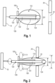
- Fig. 1 illustrates a fastening element 100 for fastening a first component 10 to a second component 20.
- the second component 20 may be, for example, a structural part of e.g. an aircraft, vehicle, or the like.
- the first component 10 may be, for example, any part that is to be fastened to the second component 20, such as a cladding part, a further structural part, or the like. It is understood that the first component 10 and the second component 20 are not limited to these examples, but the fastening element 100 may also fasten differently configured components to each other.
- the second component 20 may have an opening 22, through which the fastening element 100 may be inserted depending on its state.
- the fastening element 100 according to Fig. 1 is in an unactuated, non-elongated state.
- the fastening element 100 comprises an elastically deformable body 110.
- the body 110 of the fastening element has material properties, e.g. elastic properties, that make it elongatable, stretchable, or the like under, e.g. tensile, load and return at least substantially to its original shape without load.
- the body 110 may be formed from an elastic plastic material, particularly a rubber and/or an elastomer.
- the material may be selected from rubber, e.g.
- any vulcanizate of natural and synthetic rubbers styrene-butadiene rubber, butadiene rubber (BR), acrylonitrile-butadiene rubber (NBR), butyl rubber (IIR), ethylene-propylene-diene rubber (EPDM), chloroprene rubber (CR), polyisoprene rubber (IR), and any suitable elastomer.
- the fastening element 100 comprises an elongated actuating member 120.
- the actuating member 120 is movably guided relative to the body 110 to be selectively movable further into or further out of the body 110.
- the body 110 is configured to be elongated by moving the actuating member 120 further into the body 110 and applying a corresponding load onto the body 110.
- the body 110 is configured to elastically deform back, i.e. relax, by moving the actuating member 120 further out of the body 110 and releasing the load applied thereto.
- the body 110 is configured to have a smaller outer diameter when correspondingly elongated than when non-elongated and/or deformed back, i.e. when relaxed.
- the actuating member 120 is rather moved further out of the body 110. Accordingly, the body 110 has a first outer diameter D1, which is relatively large. According to Fig. 1 , the first outer diameter D1 is, for example, larger than a diameter (not denoted, however, see Fig. 2 ) of the opening 22 of the second component 20.
- the first component 10 may be attached, fastened, etc. to e.g. one longitudinal end of the actuating member 120, as indicated in Fig. 1 by a dashed arrow.
- the first component 10 may be fastened and/or attached to the fastening member 100 by using an insulation, a velcro fastener, a lining, a toothed plate, a rotary joint, a lug connection, or the like. This may be done before, during, or after the fastening element 100 is installed at the second component 20.
- Fig. 2 illustrates the fastening element 100 now in the actuated, elongated state mentioned above, i.e., a state in which the body 110 is elongated, in particular elongated by stretching, by actuation of the actuating member 120.
- the body 110 has a second diameter D2, which is smaller than the above-mentioned first diameter D1, which is also shown in dashed lines in Fig. 1 for better illustration.
- the smaller second diameter D2 is caused by the actuating member 120 moving further into the body 110 compared to the condition shown in Fig. 1 , causing the actuating member 120 to stretch and thereby elongate the body 110 along a longitudinal axis defined by, inter alia, the actuating member 120.
- the actuating member 120 is rather moved further into the body 110.
- the body 110 has the second outer diameter D2, which is relatively small.
- the second outer diameter D2 is, for example, at least slightly smaller than the diameter of the opening 22 of the second component 20. Accordingly, the body 110 may now be inserted into and/or through the opening 22. It is understood that in case the body 110 is again deformed by moving the actuating member 120 out again, thereby relaxing the body 110 along this axis, the body 110 again becomes larger in its outer diameter. In this way, a form-fit, and possibly also a force-fit, connection between the fastening element 100 and the second component 20 may be accomplished.
- Fig. 2 also indicates a possible way of actuating the fastening element 100.
- Fig. 2 indicates fingers of a user's hand with three dashed ovals and three dashed arrows. This is at least remotely similar to the actuation of a syringe, wherein the actuating member 120 may be moved relative to the body 110 in a manner similar to a plunger of a syringe using, for example, the thumb. If, for example, the thumb presses the actuating member 120 further into the body 110, the body 110 is correspondingly elongated by the load thereby applied.
- the fastening element 100 can also be installed without tools. It should be noted, however, that at least partially automated actuation is also possible, for example by using a memory shape alloy, an electro active polymer, or the like.
- the actuating member 120 may comprise a pin-shaped section 122 insertable or inserted at least in sections into the body 110.
- the pin-shaped section 122 may be configured to be brought into contact with an inner side of the body 110.
- a longitudinal end of the actuating element 120 facing the body 110 may have a contact surface 124 configured to be brought into contact with an inner side of the body 110.
- the contact surface 124 may have a larger surface than other sections of the actuating member 120.
- the contact surface 124 may be configured to have good adhesion properties with respect to the body 10.
- the contact surface 124 may be toothed, or the like.
- the fastening element 100 e.g. the actuating member 120
- the fastening element 100 may comprises a guiding member 126 fixed relative to the body 110 and having a bushing section to guide the actuating member 120 therein.
- the guiding member 126 may comprise an interface section 128 arranged outside the body 110 for gripping by a hand of a user and/or for attaching, as here in this example, the first component 10 thereto.
- the fastening member 100 may be made of one or more plastic materials.
- the fastening element 100 may be manufactured by multi-component injection molding or the like.
- the actuating member 120 may be formed at least sectionally onto the body 110.
- the actuating member 120 may, for example, be made of a suitable plastic material.
- the plastic material of the actuating member 120 may have higher mechanical strength than a material of the body 110. At least, the actuating member 120 is at least substantially non-elastic.
- the actuating member 120 may be moved further into the body 110 to elongate it as described above.
- the body 110 shown in Fig. 3A has the relatively small outer diameter, i.e. the second outer diameter D2.
- the fastening element 100 particularly the body 110, may be inserted into the opening 22 of the second component 20.
- the fastening member 100 e.g. the body 110
- the fastening member 100 may comprise a shoulder section 112 radially expanded and a section 114 that is elongatable by the actuating member 120 as described above.
- the shoulder section 112 may be positioned to abut the second component 20.
- the actuating member 120 may be moved further out of the body 110, causing it to return to its original shape or state due to its elasticity.
- the body 110 may comprise a first section 116 having a first degree of hardness and an adjoining second section 118 having a second degree of hardness, wherein the second section 118 has less hardness, i.e. is softer, than the first section 116.
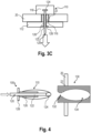
- a shape similar to a rivet as indicated in Fig. 3C may be obtained.
- Fig. 4 illustrates another example of the fastening element 100.
- the body 110 is in its elongated state as described above.
- the fastening element 100 here comprises a housing 130 configured for inserting the body 110.
- the housing 130 may have an opening 132 and may be configured to selectively accommodate at least a section of the body 110.
- the body 110 may be insertable into the housing 130 through the opening 132 when elongated and may intersect with the housing 130 when non-elongated and/or deformed back.
- the housing 130 is configured to be attached to the second component 20, as indicated in Fig. 4 .
- the housing 130 may comprise an accommodation compartment 134 configured to at least partially accommodate the body 110. Further optionally, the accommodation compartment 134 may be configured to be at least substantially airtightly sealable by the body 110.
- Fig. 5 illustrates the fastening element 100 with the housing 130 of Fig. 4 after insertion of the body 110 into the housing 130 with its non-elongated, i.e. relaxed, body 110 as the actuating member 120 has been moved further out the body 110. Accordingly, the body 110 intersects the housing 130, thereby causing a form-fit connection. It is noted that, due to the above-mentioned airtightly sealing, the body 110 may create a vacuum under its surface through its expansion and may increase the load resistance of the fastening element 100 or the fastening connection, respectively.
- Fig. 6 illustrates another example of the fastening element 100.
- the above-mentioned shoulder section 112 of the fastening element 100 is omitted.
- the above-mentioned sections 116, 118 having different degrees of hardness are omitted. As mentioned above, those sections 112, 116, 118 are merely optional.
- Fig. 6 illustrates the fastening arrangement of the fastening element 100 being attached and/or coupled to the second component 20 and the first component 10 being attached and/or coupled to the fastening element 100.
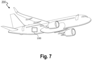
- Fig. 7 illustrates an exemplary aircraft 200 to which the fastening element 100 described herein is applied. It is noted that the fastening element 100 may also be applied to a vehicle, such as a motor vehicle, or the like.
Landscapes
- Engineering & Computer Science (AREA)
- General Engineering & Computer Science (AREA)
- Mechanical Engineering (AREA)
- Connection Of Plates (AREA)
Abstract
Description
- The present invention relates to a fastening element for fastening a first component to a second component. Further, the invention relates to a method for fastening a first component to a second component. In addition, the invention relates to an aircraft comprising at least one such fastening element.
- There are numerous applications conceivable for a fastening element for fastening a first component to a second component. By way of example, in an aircraft, vehicle, or the like, such fastening element may be used to fasten, for example, a cladding part or the like, as an example for one component, to a structural part, as an example for another component. It can be challenging that vibrations, oscillations, shocks, or the like may be transferred between the two components via the fastening element. In addition, it may be challenging that fastening elements are often designed for a clip connection, snap connection, or the like, which can be cumbersome to install, in particular in high volumes.
- One of the objects of the invention is to provide improved solutions for fastening a first component to a second component. The object is solved by the subject-matter of the appended independent claims. Further embodiments are set out in the appended dependent claims.
- According to a first aspect, there is provided a fastening element for fastening a first component to a second component. The fastening element comprises an elastically deformable body. Further, the fastening element comprises an elongated actuating member. The actuating member is guided movable relative to the body to be selectively movable further into or further out of the body. The body is configured to be elongated by moving the actuating member further into the body and applying a corresponding load onto the body. Further, the body is configured to elastically deform back by moving the actuating member further out of the body and releasing the load applied thereto. In addition, the body is configured to have a smaller outer diameter when correspondingly elongated than when non-elongated and/or deformed back.
- This configuration allows the fastening element to be easily manufactured, easily installed and/or easily used to fasten the first component to the second component in just a few steps or even in an at least partially or completely automated manner. To install the fastening element, simply actuate the actuating member to elongate the body, thereby reducing the outer diameter of the body, insert the elongated body having the smaller and/or reduced outer diameter into an opening or housing, and widen the body with respect to its outer diameter again there by releasing the actuating member and/or the load from the body. The re-deformed body may accomplish a form-fit connection, wherein a combined form-fit and force-fit connection is also possible. Due to the elastic body, i.e. the elastically deformable body, the fastening element may also serve for vibration damping, shock absorbing, sound insulation, heat insulation, or the like. For example, the elastically deformable body may serve as a load introduction part, a shock absorber, a sound barrier, a self-locking mechanism, for click and snap one-step installation, a form-fit connector, for encapsulation so as to enable fire smoke toxicity (FST) compliance, a self-helping mechanism when being under load, etc.
- As used herein, the first component may be any component that is to be fastened to another component, such as a structural part or the like. For example, the first component may be any kind of cladding part, e.g. interior cladding part, a further structural part, or the like, of an aircraft, vehicle or the like. By way of example, the second component may be any component capable of supporting a load or the like. For example, it may be a structural component or part of an aircraft, vehicle or the like. The first and second components are not limited herein, however, and a plurality of different components may be attached to each other by using the fastening element. Further, by way of example, the fastening element may be applied to an aircraft, a vehicle, or the like.
- Further, as used herein, the body of the fastening element may have material properties, particularly an elastic property, that make it elongatable, stretchable, or the like under, e.g. tensile, load and return at least substantially to its original shape without load. Accordingly, the body may be elongated, e.g., stretched, by applying the corresponding load thereto by using the actuating member. When the material of the body is elongated, e.g. stretched, it distributes along a corresponding elongation axis, e.g. stretch axis, reducing the outer diameter of the body accordingly. When the actuating member then releases the load from the body again, the body may return at least substantially or completely to its original, i.e., unloaded, shape. Accordingly, the material of the body is then no longer distributed along the elongation axis, but is again concentrated in less space, so that the outer diameter of the body is again larger compared to the elongated state. Also, the elastic and/or soft material properties of the body may also contribute, for example, to vibration damping, sound insulation, thermal insulation, or the like. The elongated, e.g. stretched and/or loaded, state of the body may serve for installation of the fastening element. The re-deformed and/or non-elongated, e.g. unstretched and/or unloaded, state of the body may serve as the intended installed state after installation.
- The fastening member may be made of one or more plastic materials. For example, the fastening element may be manufactured by multi-component injection molding or the like. Accordingly, the actuating member may be formed at least sectionally onto the body. The actuating member may, for example, be made of a suitable plastic material. The plastic material of the actuating member may have higher mechanical strength than a material of the body. At least, the actuating member is at least substantially non-elastic.
- To fasten the first component to the second component, in the installed state, the body may face or be associated with the second component, for example, and the first component may be fastened to e.g. the actuating member or another section of the fastening element. Further, by way of example, one of the first and the second component may be fastened and/or attached to the fastening member by using an insulation, a velcro fastener, a lining, a toothed plate, a rotary joint, a lug connection, or the like.
- According to at least some embodiments, the fastening element may be configured to be inserted into an opening of one of the first component and the second component when the body is elongated, stretched, or the like. The fastening element may be further configured to make at least a form-fit connection with the opening and/or with the one of the first component and the second component when the body is non-elongated and/or deformed back. Alternatively, the fastening element may be configured to be inserted into a housing, e.g. through an opening of the housing, when the body is elongated, stretched, or the like. The fastening element may be further configured to make at least a form-fit connection with the housing when the body is non-elongated and/or deformed back. This makes the fastening element easy to install and provides a robust connection.
- In at least some embodiments, the actuating member may comprise a pin-shaped section insertable or inserted at least in sections into the body and contactable or contacted with an inner side of the body. For example, the pin-shaped section may be at least sectionally inserted into the body with a longitudinal end. The corresponding longitudinal end may then abut the body from inside and elongate it, e.g. stretch it, according to the inward movement. Due to the pin shape, the actuating member requires only little installation space. In addition, this is a structurally simple design, which can also be manufactured easily.
- According to at least some embodiments, a longitudinal end of the actuating element facing the body may have a contact surface configured to be brought into contact with an inner side of the body. For example, the contact surface may have a larger surface than other sections of the actuating member. This may keep the force per area acting on the body low so that the body is not punctured. Furthermore, the contact surface may be configured to have good adhesion properties with respect to the body. For example, the contact surface may be toothed.
- In at least some embodiments, the fastening member may comprise a guiding member fixed relative to the body and having a bushing section to guide the actuating member therein. The guiding member may also be a section of the actuating member. The guiding member may be manufactured from the same or a different plastic material as the fastening member. The bushing section may extend into the body to provide rigid guidance for the actuating member, e.g., its pin-shaped section. For example, the actuating member may have a bushing with a pin guided therein. The pin may be movable within the bushing along its longitudinal direction to selectively elongate or relax the body.
- According to at least some embodiments, the guiding member may comprise an interface section arranged outside the body for gripping by a hand of a user and/or for attaching one of the first component and the second component thereto. For example, the interface section may be configured similar to a syringe, so that it can be operated with, in principle, three fingers. The interface section may serve as a kind of abutment when the actuating member is pressed into the body, similar to the plunger of a syringe. Additionally or simultaneously, the interface section or a longitudinal end of the actuating member facing away from the body may be configured to or serve to attach one of the first component and the second component thereto.
- In at least some embodiments, the body may comprise a first section having a first degree of hardness and an adjoining second section having a second degree of hardness. The second section may have less hardness than the first section. For example, the hardness may be indicated by e.g. shore hardness, or the like. For example, the softer section may form a longitudinal end of the body. Due to the softer material properties of this section, the body, in particular when non-elongated, may have an even larger outer diameter than the other section of the body, which is harder compared thereto. This allows a rivet-like shape of the body, especially after its installation and/or when non-elongated, and/or a rivet-like connection.
- According to at least some embodiments, the body may comprise a shoulder section radially expanded and a section elongatable by the actuating member. For example, the section elongatable may be inserted through an opening. The shoulder may then abut at the corresponding component having the opening. The abutting shoulder section may further improve the installation of the fastening member.
- In at least some embodiments, the fastening member may further comprise a housing. The housing may have an opening. Further, the housing may be configured to selectively accommodate at least a section of the body. The body may be configured to be insertable through the opening into the housing when elongated and may intersect with the housing when non-elongated and/or deformed back. Thus, there may be provided a fit-fit connection between the fastening member and the housing. For example, the housing may be fastened and/or attached to one of the first component and the second component. Alternatively or additionally, the housing may be integrally formed with one of the first component and the second component.
- According to at least some embodiments, the housing may be configured to be fastened and/or attached to one of the first component and the second component. The other one of the first and second component may be fastened and/or attached to the fastening member. For example, housing may be attached to the one of the first component and the second component by welding, a screw connection, or any other suitable joining technique, or may be formed integrally therewith.
- In at least some embodiments, the housing may comprise an accommodation compartment configured to at least partially and/or sectionally accommodate the body. The accommodation compartment may be configured to be at least substantially airtightly sealable by the body. For example, an opening of the housing may open into the compartment. This opening may be at least partially closed by the body inserted in the compartment, like a plug that closes an opening, in this case from the inside, i.e. from the compartment-side. By varying the outer diameter of the body, i.e., by moving the actuating member relative to the body, this may generate a negative pressure, possibly a substantial vacuum, inside the housing. This allows an even stronger, more reliable and/or more robust fastening to be achieved.
- According to at least some embodiments, the body may be formed from an elastic plastic material, particularly a rubber and/or an elastomer. The material used should have elastic properties. For example, the material may be selected from rubber, e.g. any vulcanizate of natural and synthetic rubbers, styrene-butadiene rubber, butadiene rubber (BR), acrylonitrile-butadiene rubber (NBR), butyl rubber (IIR), ethylene-propylene-diene rubber (EPDM), chloroprene rubber (CR), polyisoprene rubber (IR), and any suitable elastomer.
- According to a second aspect of the invention, there is provided a method for fastening a first component to a second component. The method comprises providing a fastening element according to the first aspect. Further, the method comprises elongating the body of the fastening element by moving the actuating member further into the body and inserting the elongated body into an opening of one of the first component and the second component or into an opening of a housing coupled to one of the first component and the second component. In addition, the method comprises moving the actuating member further out of the body to expand the outer diameter of the body and to effect at least a form-fit connection with the one of the first component and the second component or with the housing.
- Accordingly, the fastening element according to the first aspect or any of the embodiments as described herein may be used to fasten the first component to the second component. The method may be modified according to any embodiment of the fastening element described herein. The method provides a structurally simple and robust fastening option that is also easy to install.
- In at least some embodiments, the method may further comprise attaching the other one of the first component and the second component to the fastening element, particularly to the actuating member. For example, the other one of the first and the second component may be fastened and/or attached to the fastening member by using an insulation, a velcro fastener, a lining, a toothed plate, a rotary joint, a lug connection, or the like.
- According to a third aspect of the invention, there is provided an aircraft. The aircraft comprises at least one fastening element according to the first aspect used for fastening a first component to a second component of the aircraft.
- Another aspect of the invention provides an arrangement of a first component and a second component. One of the first and the second component may be fastened to the other by using at least one fastening element as described herein.
- The above configurations and refinements may be combined with one another as desired where expedient. Further possible embodiments, refinements and implementations of the invention also encompass combinations, which are not explicitly mentioned, of features of the invention described above or below with regard to the exemplary embodiments. In particular, a person skilled in the art will also add individual aspects as improvements or additions to the respective basic form of the present invention.
- The present invention is explained in more detail below with reference to the embodiments shown in the schematic figures:
- Fig. 1
- illustrates an exemplary, non-elongated fastening element for fastening a first component to a second component, according to an embodiment.
- Fig. 2
- illustrates an exemplary, elongated fastening element for fastening a first component to a second component, according to an embodiment.
- Fig. 3A-3C
- illustrates an exemplary installation of the fastening element into an opening, e.g. an opening of a second component.
- Fig. 4
- illustrates another exemplary, elongated fastening element with a housing for fastening a first component to a second component, according to an embodiment.
- Fig. 5
- illustrates the fastening element with the housing illustrated in
Fig. 4 in a state in which the fastening element is inserted into the housing and non-elongated. - Fig. 6
- illustrates another example of the fastening element.
- Fig. 7
- illustrates an exemplary aircraft to which a fastening element for fastening a first component to a second component according to an embodiment is applied.
- In the figures of the drawing, elements, features and components which are identical, functionally identical and of identical action are denoted in each case by the same reference designations unless stated otherwise.
-
Fig. 1 illustrates afastening element 100 for fastening afirst component 10 to asecond component 20. Thesecond component 20 may be, for example, a structural part of e.g. an aircraft, vehicle, or the like. Thefirst component 10 may be, for example, any part that is to be fastened to thesecond component 20, such as a cladding part, a further structural part, or the like. It is understood that thefirst component 10 and thesecond component 20 are not limited to these examples, but thefastening element 100 may also fasten differently configured components to each other. In this example, thesecond component 20 may have anopening 22, through which thefastening element 100 may be inserted depending on its state. - As will become even clearer from the following description, the
fastening element 100 according toFig. 1 is in an unactuated, non-elongated state. - The
fastening element 100 comprises an elasticallydeformable body 110. Thebody 110 of the fastening element has material properties, e.g. elastic properties, that make it elongatable, stretchable, or the like under, e.g. tensile, load and return at least substantially to its original shape without load. For example, thebody 110 may be formed from an elastic plastic material, particularly a rubber and/or an elastomer. By way of example, the material may be selected from rubber, e.g. any vulcanizate of natural and synthetic rubbers, styrene-butadiene rubber, butadiene rubber (BR), acrylonitrile-butadiene rubber (NBR), butyl rubber (IIR), ethylene-propylene-diene rubber (EPDM), chloroprene rubber (CR), polyisoprene rubber (IR), and any suitable elastomer. - Further, the
fastening element 100 comprises anelongated actuating member 120. The actuatingmember 120 is movably guided relative to thebody 110 to be selectively movable further into or further out of thebody 110. Further, thebody 110 is configured to be elongated by moving the actuatingmember 120 further into thebody 110 and applying a corresponding load onto thebody 110. Likewise, thebody 110 is configured to elastically deform back, i.e. relax, by moving the actuatingmember 120 further out of thebody 110 and releasing the load applied thereto. Further, thebody 110 is configured to have a smaller outer diameter when correspondingly elongated than when non-elongated and/or deformed back, i.e. when relaxed. - In the unactuated, non-elongated state according to
Fig. 1 , the actuatingmember 120 is rather moved further out of thebody 110. Accordingly, thebody 110 has a first outer diameter D1, which is relatively large. According toFig. 1 , the first outer diameter D1 is, for example, larger than a diameter (not denoted, however, seeFig. 2 ) of theopening 22 of thesecond component 20. - It is noted that the
first component 10 may be attached, fastened, etc. to e.g. one longitudinal end of the actuatingmember 120, as indicated inFig. 1 by a dashed arrow. For example, thefirst component 10 may be fastened and/or attached to thefastening member 100 by using an insulation, a velcro fastener, a lining, a toothed plate, a rotary joint, a lug connection, or the like. This may be done before, during, or after thefastening element 100 is installed at thesecond component 20. -
Fig. 2 illustrates thefastening element 100 now in the actuated, elongated state mentioned above, i.e., a state in which thebody 110 is elongated, in particular elongated by stretching, by actuation of the actuatingmember 120. Accordingly, inFig. 2 , thebody 110 has a second diameter D2, which is smaller than the above-mentioned first diameter D1, which is also shown in dashed lines inFig. 1 for better illustration. As described above, the smaller second diameter D2 is caused by the actuatingmember 120 moving further into thebody 110 compared to the condition shown inFig. 1 , causing the actuatingmember 120 to stretch and thereby elongate thebody 110 along a longitudinal axis defined by, inter alia, the actuatingmember 120. - In the actuated, elongated state according to
Fig. 2 , the actuatingmember 120 is rather moved further into thebody 110. Accordingly, thebody 110 has the second outer diameter D2, which is relatively small. According toFig. 2 , the second outer diameter D2 is, for example, at least slightly smaller than the diameter of theopening 22 of thesecond component 20. Accordingly, thebody 110 may now be inserted into and/or through theopening 22. It is understood that in case thebody 110 is again deformed by moving the actuatingmember 120 out again, thereby relaxing thebody 110 along this axis, thebody 110 again becomes larger in its outer diameter. In this way, a form-fit, and possibly also a force-fit, connection between thefastening element 100 and thesecond component 20 may be accomplished. - It is noted that
Fig. 2 also indicates a possible way of actuating thefastening element 100. For example,Fig. 2 indicates fingers of a user's hand with three dashed ovals and three dashed arrows. This is at least remotely similar to the actuation of a syringe, wherein the actuatingmember 120 may be moved relative to thebody 110 in a manner similar to a plunger of a syringe using, for example, the thumb. If, for example, the thumb presses the actuatingmember 120 further into thebody 110, thebody 110 is correspondingly elongated by the load thereby applied. If the load exerted by, for example, the thumb on the actuatingmember 120 is released, theelastic body 110 returns to its original, non-elongated shape. If necessary, the actuatingmember 120 may also be actively pulled out again. Accordingly, thefastening element 100 can also be installed without tools. It should be noted, however, that at least partially automated actuation is also possible, for example by using a memory shape alloy, an electro active polymer, or the like. - Still referring to
Fig. 1 and/orFig. 2 , some optional features of thefastening element 100 will be explained in the following. - In at least some embodiments, the actuating
member 120 may comprise a pin-shapedsection 122 insertable or inserted at least in sections into thebody 110. The pin-shapedsection 122 may be configured to be brought into contact with an inner side of thebody 110. - Further, in at least some embodiments, a longitudinal end of the
actuating element 120 facing thebody 110 may have acontact surface 124 configured to be brought into contact with an inner side of thebody 110. For example, thecontact surface 124 may have a larger surface than other sections of the actuatingmember 120. Further, thecontact surface 124 may be configured to have good adhesion properties with respect to thebody 10. For example, thecontact surface 124 may be toothed, or the like. - Furthermore, in at least some embodiments, the
fastening element 100, e.g. the actuatingmember 120, may comprises a guidingmember 126 fixed relative to thebody 110 and having a bushing section to guide the actuatingmember 120 therein. Also, in at least some embodiments, the guidingmember 126 may comprise aninterface section 128 arranged outside thebody 110 for gripping by a hand of a user and/or for attaching, as here in this example, thefirst component 10 thereto. - The
fastening member 100 may be made of one or more plastic materials. For example, thefastening element 100 may be manufactured by multi-component injection molding or the like. Accordingly, the actuatingmember 120 may be formed at least sectionally onto thebody 110. The actuatingmember 120 may, for example, be made of a suitable plastic material. The plastic material of the actuatingmember 120 may have higher mechanical strength than a material of thebody 110. At least, the actuatingmember 120 is at least substantially non-elastic. - With reference to
Fig. 3 to Fig. 5 , an exemplary installation of thefastening element 100 in an opening, e.g. the above-mentionedopening 22 of thesecond component 20, will now be explained in the following. - It is noted that this exemplary installation may be performed using the
fastening element 100 ofFig. 1 and Fig. 2 . However,Fig. 3A to Fig. 3C will also be used here to explain further optional features of thefastening element 100. - First, referring to
Fig. 3A , the actuatingmember 120 may be moved further into thebody 110 to elongate it as described above. Accordingly, thebody 110 shown inFig. 3A has the relatively small outer diameter, i.e. the second outer diameter D2. Then, referring toFig. 3B , thefastening element 100, particularly thebody 110, may be inserted into theopening 22 of thesecond component 20. Optionally, as indicated inFig. 3B , thefastening member 100, e.g. thebody 110, may comprise ashoulder section 112 radially expanded and a section 114 that is elongatable by the actuatingmember 120 as described above. Theshoulder section 112 may be positioned to abut thesecond component 20. Then, referring toFig. 3C , the actuatingmember 120 may be moved further out of thebody 110, causing it to return to its original shape or state due to its elasticity. Optionally, as indicated inFig. 3C , thebody 110 may comprise afirst section 116 having a first degree of hardness and an adjoiningsecond section 118 having a second degree of hardness, wherein thesecond section 118 has less hardness, i.e. is softer, than thefirst section 116. With this optional embodiment of thebody 110, a shape similar to a rivet as indicated inFig. 3C may be obtained. -
Fig. 4 illustrates another example of thefastening element 100. InFig. 4 , thebody 110 is in its elongated state as described above. Deviating from and optional to the embodiments described above, thefastening element 100 here comprises ahousing 130 configured for inserting thebody 110. Thehousing 130 may have anopening 132 and may be configured to selectively accommodate at least a section of thebody 110. Thebody 110 may be insertable into thehousing 130 through theopening 132 when elongated and may intersect with thehousing 130 when non-elongated and/or deformed back. Thehousing 130 is configured to be attached to thesecond component 20, as indicated inFig. 4 . Further, thehousing 130 may comprise anaccommodation compartment 134 configured to at least partially accommodate thebody 110. Further optionally, theaccommodation compartment 134 may be configured to be at least substantially airtightly sealable by thebody 110. -
Fig. 5 illustrates thefastening element 100 with thehousing 130 ofFig. 4 after insertion of thebody 110 into thehousing 130 with its non-elongated, i.e. relaxed,body 110 as the actuatingmember 120 has been moved further out thebody 110. Accordingly, thebody 110 intersects thehousing 130, thereby causing a form-fit connection. It is noted that, due to the above-mentioned airtightly sealing, thebody 110 may create a vacuum under its surface through its expansion and may increase the load resistance of thefastening element 100 or the fastening connection, respectively. -
Fig. 6 illustrates another example of thefastening element 100. Here, the above-mentionedshoulder section 112 of thefastening element 100 is omitted. Further, here, the above-mentionedsections sections Fig. 6 illustrates the fastening arrangement of thefastening element 100 being attached and/or coupled to thesecond component 20 and thefirst component 10 being attached and/or coupled to thefastening element 100. -
Fig. 7 illustrates anexemplary aircraft 200 to which thefastening element 100 described herein is applied. It is noted that thefastening element 100 may also be applied to a vehicle, such as a motor vehicle, or the like. -
- 10
- first component
- 20
- second component
- 22
- opening
- 100
- fastening element
- 110
- elastic body
- 112
- shoulder section
- 114
- elongatable section
- 116
- section of first hardness
- 118
- section of second hardness
- 120
- actuating member
- 122
- pin-shaped section
- 124
- contact surface
- 126
- guiding member
- 128
- interface section
- 130
- housing
- 132
- opening
- 134
- compartment
- 200
- aircraft
Claims (15)
- A fastening element (100) for fastening a first component (10) to a second component (20), the fastening element (100) comprising:an elastically deformable body (110); andan elongated actuating member (120), movably guided relative to the body (110) to be selectively movable further into or further out of the body (110), wherein the body (110) is configured to be elongated by moving the actuating member (120) further into the body (110) and applying a corresponding load onto the body (110) and to elastically deform back by moving the actuating member (120) further out of the body (110) and releasing the load applied thereto, and the body (110) is configured to have a smaller outer diameter (D2) when correspondingly elongated than when non-elongated and/or deformed back.
- The fastening element of claim 1, wherein the fastening element (100) is configured to be inserted into an opening (22) of one of the first component (10) and the second component (20) or of a housing (130) when the body (110) is elongated, and to make at least a form-fit connection with it when the body (110) is non-elongated and/or deformed back.
- The fastening element of claim 1 or 2, wherein the actuating member (120) comprises a pin-shaped section (122) insertable or inserted at least in sections into the body (110) and contactable or contacted with an inner side of the body (110).
- The fastening element of any one of the preceding claims, wherein a longitudinal end of the actuating element (120) facing the body (110) has a contact surface (124) configured to be brought into contact with an inner side of the body (110).
- The fastening element of any one of the preceding claims, further comprising a guiding member (126) fixed relative to the body (110) and having a bushing section to guide the actuating member (120) therein.
- The fastening element of claim 5, wherein the guiding member (126) comprises an interface section (128) arranged outside the body (110) for gripping by a hand of a user and/or for attaching one of the first component (10) and the second component (20) thereto.
- The fastening element of any one of the preceding claims, wherein the body (110) comprises a first section (116) having a first degree of hardness and an adjoining second section (118) having a second degree of hardness, and the second section (118) has less hardness than the first section (116).
- The fastening element of any one of the preceding claims, wherein the body (110) comprises a shoulder section (112) radially expanded and a section elongatable by the actuating member (120).
- The fastening element of any one of the preceding claims, further comprising a housing (130), having an opening (132) and configured to selectively accommodate at least a section of the body (110), the body (110) being insertable through the opening (132) into the housing (130) when elongated and intersect with the housing (130) when non-elongated and/or deformed back.
- The fastening element of claim 9, wherein the housing (130) is configured to be attached to one of the first component (10) and the second component (20).
- The fastening element of claim 9 or 10, wherein the housing (130) comprises an accommodation compartment (134) configured to at least partially accommodate the body (110), and the accommodation compartment (134) is configured to be at least substantially airtightly sealable by the body (110).
- The fastening element of any one of the preceding claims, wherein the body (110) is formed from an elastic plastic material, particularly a rubber and/or an elastomer.
- A method for fastening a first component (10) to a second component (20), the method comprising:providing a fastening element (100) according to any one of the preceding claims;elongating the body (110) of the fastening element (100) by moving the actuating member (120) further into the body (110) and inserting the elongated body (110) into an opening (22) of one of the first component (10) and the second component (20) or into an opening (132) of a housing (130) coupled to one of the first component (10) and the second component (20); andmoving the actuating member (120) further out of the body (110) to expand the outer diameter of the body (110) and to effect at least a form-fit connection with the one of the first component (10) and the second component (20) or with the housing (130).
- The method of claim 13, further comprising attaching the other one of the first component (10) and the second component (20) to the fastening element (200), particularly to the actuating member (120).
- An aircraft (200), comprising at least one fastening element (100) according to any one of claims 1 to 12 used for fastening a first component (10) to a second component (20) of the aircraft (200).
Priority Applications (3)
| Application Number | Priority Date | Filing Date | Title |
|---|---|---|---|
| EP23175049.8A EP4467821A1 (en) | 2023-05-24 | 2023-05-24 | Fastening element with selectively elongatable body |
| US18/654,189 US12429079B2 (en) | 2023-05-24 | 2024-05-03 | Fastening element with selectively elongatable body |
| CN202410638711.5A CN119021955A (en) | 2023-05-24 | 2024-05-22 | Fastening element, method for fastening a first component to a second component, and aircraft |
Applications Claiming Priority (1)
| Application Number | Priority Date | Filing Date | Title |
|---|---|---|---|
| EP23175049.8A EP4467821A1 (en) | 2023-05-24 | 2023-05-24 | Fastening element with selectively elongatable body |
Publications (1)
| Publication Number | Publication Date |
|---|---|
| EP4467821A1 true EP4467821A1 (en) | 2024-11-27 |
Family
ID=86603766
Family Applications (1)
| Application Number | Title | Priority Date | Filing Date |
|---|---|---|---|
| EP23175049.8A Pending EP4467821A1 (en) | 2023-05-24 | 2023-05-24 | Fastening element with selectively elongatable body |
Country Status (3)
| Country | Link |
|---|---|
| US (1) | US12429079B2 (en) |
| EP (1) | EP4467821A1 (en) |
| CN (1) | CN119021955A (en) |
Citations (4)
| Publication number | Priority date | Publication date | Assignee | Title |
|---|---|---|---|---|
| GB774002A (en) * | 1954-08-26 | 1957-05-01 | L H Newton & Co Ltd | Anchorage bolts |
| DE29804519U1 (en) * | 1997-03-17 | 1998-06-10 | S.I.A.P. S.r.l., Coccaglio, Brescia | Device for connecting a seat and a cover with a toilet key |
| DE202015103074U1 (en) * | 2015-06-12 | 2015-07-15 | Vetter Vorrichtungsbau GmbH | Fastening device for a toilet unit |
| US20210361130A1 (en) * | 2017-07-11 | 2021-11-25 | Cassellie Ltd | Engagement apparatus |
Family Cites Families (3)
| Publication number | Priority date | Publication date | Assignee | Title |
|---|---|---|---|---|
| DE4034129C1 (en) * | 1990-10-26 | 1992-05-07 | Gkn Cardantec International Gesellschaft Fuer Antriebstechnik Mbh, 4300 Essen, De | |
| DE102007009692A1 (en) * | 2007-02-28 | 2008-09-04 | Robert Bosch Gmbh | Accident sensor has fastening medium for fastening accident sensor to wall in vehicle, and hole is provided, which has bolt in elastically designed sleeve as fastening medium |
| US11428257B2 (en) * | 2018-09-24 | 2022-08-30 | Liquidmetal Technologies, Inc. | Amorphous metal rivet systems |
-
2023
- 2023-05-24 EP EP23175049.8A patent/EP4467821A1/en active Pending
-
2024
- 2024-05-03 US US18/654,189 patent/US12429079B2/en active Active
- 2024-05-22 CN CN202410638711.5A patent/CN119021955A/en active Pending
Patent Citations (4)
| Publication number | Priority date | Publication date | Assignee | Title |
|---|---|---|---|---|
| GB774002A (en) * | 1954-08-26 | 1957-05-01 | L H Newton & Co Ltd | Anchorage bolts |
| DE29804519U1 (en) * | 1997-03-17 | 1998-06-10 | S.I.A.P. S.r.l., Coccaglio, Brescia | Device for connecting a seat and a cover with a toilet key |
| DE202015103074U1 (en) * | 2015-06-12 | 2015-07-15 | Vetter Vorrichtungsbau GmbH | Fastening device for a toilet unit |
| US20210361130A1 (en) * | 2017-07-11 | 2021-11-25 | Cassellie Ltd | Engagement apparatus |
Also Published As
| Publication number | Publication date |
|---|---|
| US12429079B2 (en) | 2025-09-30 |
| CN119021955A (en) | 2024-11-26 |
| US20240392820A1 (en) | 2024-11-28 |
Similar Documents
| Publication | Publication Date | Title |
|---|---|---|
| US8827214B2 (en) | Clamp | |
| US7011277B2 (en) | Antivibration clamp for elongated objects | |
| KR101335080B1 (en) | Grommet for wire harness | |
| US7257867B2 (en) | Clip for attaching two members | |
| JP4700868B2 (en) | Tube support clamp | |
| CN106499761B (en) | Antihunting device | |
| US9739327B2 (en) | Cushion clip | |
| US8677563B2 (en) | Trunk cushion | |
| JP2003329022A (en) | Human engineering fastener | |
| EP3406472A1 (en) | Sealing clip | |
| WO2006057150A1 (en) | Shock-absorbing clip | |
| US9004416B2 (en) | Clamp | |
| EP3974692A1 (en) | A support clip for elongated component(s) | |
| US12429079B2 (en) | Fastening element with selectively elongatable body | |
| KR20190135083A (en) | Dynamic damper | |
| EP2408596A1 (en) | Mounting system for a gas gun | |
| JP2010001967A (en) | Cushion clip | |
| JP2008196651A (en) | Cushion clip | |
| US9181745B1 (en) | Trunk cushion assembly | |
| US20200392765A1 (en) | Striker mounted endgate damper | |
| JP2006052806A (en) | Cushion clip | |
| US10753510B2 (en) | Conduit guide for guiding at least one conduit section between two elements | |
| CN115450512A (en) | Back door buffer component, automobile back door system and automobile | |
| JP5533368B2 (en) | Sound insulation structure of grommet mounting part | |
| EP4361481B1 (en) | A support clip for elongated components |
Legal Events
| Date | Code | Title | Description |
|---|---|---|---|
| PUAI | Public reference made under article 153(3) epc to a published international application that has entered the european phase |
Free format text: ORIGINAL CODE: 0009012 |
|
| STAA | Information on the status of an ep patent application or granted ep patent |
Free format text: STATUS: THE APPLICATION HAS BEEN PUBLISHED |
|
| AK | Designated contracting states |
Kind code of ref document: A1 Designated state(s): AL AT BE BG CH CY CZ DE DK EE ES FI FR GB GR HR HU IE IS IT LI LT LU LV MC ME MK MT NL NO PL PT RO RS SE SI SK SM TR |
|
| STAA | Information on the status of an ep patent application or granted ep patent |
Free format text: STATUS: REQUEST FOR EXAMINATION WAS MADE |
|
| 17P | Request for examination filed |
Effective date: 20250527 |
|
| STAA | Information on the status of an ep patent application or granted ep patent |
Free format text: STATUS: EXAMINATION IS IN PROGRESS |
|
| 17Q | First examination report despatched |
Effective date: 20260218 |