EP4467811A1 - Variable displacement pump systems - Google Patents
Variable displacement pump systems Download PDFInfo
- Publication number
- EP4467811A1 EP4467811A1 EP24177440.5A EP24177440A EP4467811A1 EP 4467811 A1 EP4467811 A1 EP 4467811A1 EP 24177440 A EP24177440 A EP 24177440A EP 4467811 A1 EP4467811 A1 EP 4467811A1
- Authority
- EP
- European Patent Office
- Prior art keywords
- cam ring
- radial
- pump
- actuators
- rotor
- Prior art date
- Legal status (The legal status is an assumption and is not a legal conclusion. Google has not performed a legal analysis and makes no representation as to the accuracy of the status listed.)
- Pending
Links
Images


Classifications
-
- F—MECHANICAL ENGINEERING; LIGHTING; HEATING; WEAPONS; BLASTING
- F04—POSITIVE - DISPLACEMENT MACHINES FOR LIQUIDS; PUMPS FOR LIQUIDS OR ELASTIC FLUIDS
- F04C—ROTARY-PISTON, OR OSCILLATING-PISTON, POSITIVE-DISPLACEMENT MACHINES FOR LIQUIDS; ROTARY-PISTON, OR OSCILLATING-PISTON, POSITIVE-DISPLACEMENT PUMPS
- F04C2/00—Rotary-piston machines or pumps
- F04C2/30—Rotary-piston machines or pumps having the characteristics covered by two or more groups F04C2/02, F04C2/08, F04C2/22, F04C2/24 or having the characteristics covered by one of these groups together with some other type of movement between co-operating members
- F04C2/34—Rotary-piston machines or pumps having the characteristics covered by two or more groups F04C2/02, F04C2/08, F04C2/22, F04C2/24 or having the characteristics covered by one of these groups together with some other type of movement between co-operating members having the movement defined in groups F04C2/08 or F04C2/22 and relative reciprocation between the co-operating members
- F04C2/344—Rotary-piston machines or pumps having the characteristics covered by two or more groups F04C2/02, F04C2/08, F04C2/22, F04C2/24 or having the characteristics covered by one of these groups together with some other type of movement between co-operating members having the movement defined in groups F04C2/08 or F04C2/22 and relative reciprocation between the co-operating members with vanes reciprocating with respect to the inner member
-
- F—MECHANICAL ENGINEERING; LIGHTING; HEATING; WEAPONS; BLASTING
- F04—POSITIVE - DISPLACEMENT MACHINES FOR LIQUIDS; PUMPS FOR LIQUIDS OR ELASTIC FLUIDS
- F04C—ROTARY-PISTON, OR OSCILLATING-PISTON, POSITIVE-DISPLACEMENT MACHINES FOR LIQUIDS; ROTARY-PISTON, OR OSCILLATING-PISTON, POSITIVE-DISPLACEMENT PUMPS
- F04C14/00—Control of, monitoring of, or safety arrangements for, machines, pumps or pumping installations
- F04C14/18—Control of, monitoring of, or safety arrangements for, machines, pumps or pumping installations characterised by varying the volume of the working chamber
-
- F—MECHANICAL ENGINEERING; LIGHTING; HEATING; WEAPONS; BLASTING
- F04—POSITIVE - DISPLACEMENT MACHINES FOR LIQUIDS; PUMPS FOR LIQUIDS OR ELASTIC FLUIDS
- F04C—ROTARY-PISTON, OR OSCILLATING-PISTON, POSITIVE-DISPLACEMENT MACHINES FOR LIQUIDS; ROTARY-PISTON, OR OSCILLATING-PISTON, POSITIVE-DISPLACEMENT PUMPS
- F04C14/00—Control of, monitoring of, or safety arrangements for, machines, pumps or pumping installations
- F04C14/18—Control of, monitoring of, or safety arrangements for, machines, pumps or pumping installations characterised by varying the volume of the working chamber
- F04C14/22—Control of, monitoring of, or safety arrangements for, machines, pumps or pumping installations characterised by varying the volume of the working chamber by changing the eccentricity between cooperating members
- F04C14/223—Control of, monitoring of, or safety arrangements for, machines, pumps or pumping installations characterised by varying the volume of the working chamber by changing the eccentricity between cooperating members using a movable cam
-
- F—MECHANICAL ENGINEERING; LIGHTING; HEATING; WEAPONS; BLASTING
- F04—POSITIVE - DISPLACEMENT MACHINES FOR LIQUIDS; PUMPS FOR LIQUIDS OR ELASTIC FLUIDS
- F04C—ROTARY-PISTON, OR OSCILLATING-PISTON, POSITIVE-DISPLACEMENT MACHINES FOR LIQUIDS; ROTARY-PISTON, OR OSCILLATING-PISTON, POSITIVE-DISPLACEMENT PUMPS
- F04C2240/00—Components
- F04C2240/80—Other components
- F04C2240/811—Actuator for control, e.g. pneumatic, hydraulic, electric
Definitions
- This disclosure relates to variable displacement pump systems.
- a variable displacement pump can include a rotor having a plurality of vanes, and a cam ring surrounding the rotor and vanes.
- the vanes can be configured to extend from the rotor and contact an inner cam surface of the cam ring.
- the pump can also include one or more radial actuators configured to apply a radial force to the cam ring to control a position of the cam ring and the pumping action.
- the one or more radial actuators are or include an electromechanical actuator.
- the pump can include a controller configured to directly control the one or more radial actuators to achieve a desired pumping action.
- the pump can include one or more biasing members configured to provide an opposing force to a direction of force applied by the one or more radial actuators to bias the cam ring in a bias direction.
- the bias direction can be a maximum pumping action direction.
- the pump can include an alignment shaft for each biasing member (e.g., configured to radially align a biasing force of the biasing member).
- the one or more radial actuators are configured to apply the radial force in a radial direction that intersects a rotational axis of the rotor.
- the one or more biasing members can be configured to apply the opposing force in an opposite direction of the radial direction which also intersects the rotational axis of the rotor.
- the one or more radial actuators and the one or more biasing members can be positioned on an opposite side of the cam ring 180 degrees apart. In certain embodiments, the one or more radial actuators and the one or more biasing members can be positioned on a same side of the cam ring.
- the one or more biasing members can include a plurality of biasing members. In certain embodiments, one or more of the plurality of biasing members are positioned on an opposite side of the cam ring 180 degrees apart from the one or more radial actuators, and one or more of the plurality of the biasing members can be positioned on a same side of the cam ring as the one or more radial actuators and are aligned with the one or more radial actuators.
- the one or more radial actuators can include a plurality of radial actuators.
- the plurality of radial actuators can be aligned axially on a single side of the cam ring such that the radial force from each radial actuator passes through the rotational axis of the rotor.
- the one or more biasing members can include one or more biasing members disposed between at least two of the plurality of actuators on a same side of the cam ring.
- a fuel system for an aircraft can include a variable displacement pump.
- the variable displacement pump can be or include any suitable pump disclosed herein, e.g., as described above.
- FIG. 1 an illustrative view of an embodiment of a pump in accordance with the disclosure is shown in Fig. 1 and is designated generally by reference character 100.
- FIGs. 2-4 Other embodiments and/or aspects of this disclosure are shown in Figs. 2-4 .
- Certain embodiments described herein can be used to provide direct control of pumping action of a variable displacement pump.
- a variable displacement pump 100 can include a rotor 101 (e.g., connected to a shaft 103) having a plurality of vanes 105, and a cam ring 107 surrounding the rotor 101 and vanes 105.
- the vanes 105 can be configured to extend from the rotor 101 and contact an inner cam surface 107a of the cam ring 107.
- the pump 100 can also include one or more radial actuators 109 configured to apply a radial force 111 to the cam ring 107 to control a position of the cam ring 107 and the pumping action (e.g., the amount of flow/pressure produced by the pump 100).
- the one or more radial actuators 109 can be or include an electromechanical actuator (EMA), e.g., as shown in Fig. 2 having an electric motor 215 attached to the actuator 109).
- the pump 100 can include a controller 113 operatively connected to and configured to directly control the one or more radial actuators 109 (e.g., the motor 215 of each radial actuator 109) to achieve a desired pumping action.
- EMA electromechanical actuator
- the pump 100 can include one or more biasing members 217 (e.g., a spring) configured to provide an opposing force 221 to a direction of force 111 (e.g., downward as shown) applied by the one or more radial actuators 109 to bias the cam ring 107 in a bias direction (e.g., upward as shown in Figs. 1 and 2 ).
- the bias direction can be a maximum pumping action direction (e.g., such that failure of the one or more actuators 109 causes maximum flow in a system, e.g., in a fuel system to ensure sufficient flow under any operational condition).
- the pump 100 can include an alignment shaft 219 for each biasing member 217 (e.g., configured to radially align a biasing force 221 of the biasing member).
- the one or more radial actuators 109 can be configured to apply the radial force 111 in a radial direction that intersects a rotational axis 123 of the rotor 101 (e.g., as shown in Figs. 1 and 2 ).
- the one or more biasing members 217 can be configured to apply the opposing force 221 in an opposite direction (e.g., upward as shown) of the radial direction which also intersects the rotational axis 123 of the rotor 101.
- the one or more radial actuators 109 and the one or more biasing members 217 can be positioned on an opposite side of the cam ring 107 at 180 degrees apart. In certain embodiments, the one or more radial actuators 109 and the one or more biasing members 217 can be positioned on a same side of the cam ring 107, e.g., as shown in pump 400 of Fig. 4 .
- the one or more biasing members 217 can include a plurality of biasing members 217 as shown in Figs. 2-4 .
- one or more of the plurality of biasing members 217 can be positioned on an opposite side of the cam ring 107 at 180 degrees apart from the one or more radial actuators 109, and one or more of the plurality of the biasing members 217 can be positioned on a same side of the cam ring 107 (e.g., at zero degrees) as the one or more radial actuators 109 and can be aligned with the one or more radial actuators 109.
- the one or more alignment shafts 219 can be coincident/coaxial with one or more of the biasing members 217, or can be positioned spaced apart therefrom in a manner that guides the cam ring 107 and/or restrains motion of the cam ring 107 to a single axis (e.g., the vertical axis as shown), for example.
- the one or more radial actuators 109 can include a plurality of radial actuators 109.
- the plurality of radial actuators 109 can be aligned axially on a single side of the cam ring 107 such that the radial force from each radial actuator 109 passes through the rotational axis 123 of the rotor 101.
- the one or more biasing members 217 can include one or more biasing members 217 disposed between at least two of the plurality of actuators 109 on a same side of the cam ring. 107 (e.g., as shown in Fig. 4 ).
- Certain embodiments can utilize tension springs for same-side springs and compression springs for opposite-side springs, for example.
- the directionality of the one or more springs can be opposite if the directionality of the one or more actuators 109 is opposite (e.g., tension spring on opposite side and compression spring on same side where the actuator is a pulling actuator).
- the biasing force direction can be the same as the actuator force direction, e.g., to reduce actuator force required to move the cam ring 107.
- the one or more actuators 109 may release when not function causing the biasing members to push the cam ring 107 toward the maximum flow position, for example. Any other suitable relative force arrangement is contemplated herein (e.g., with force constrained to a single axis).
- a fuel system for an aircraft can include a variable displacement pump.
- the variable displacement pump can be or include any suitable pump disclosed herein, e.g., pump 100, 300, 400 as described above.
- Embodiments can include an actuator applied to an outer ring of vane pump.
- One or more EMAs can push/pull the outer ring (e.g., the cam ring) of the vane pump to change displacement.
- Springs can also be incorporated by being located at either 0° or 180° locations on the outer ring depending on the travel direction that the system wants to make easier for the actuator, or to resist actuator motion.
- Alignment shafts/rods can also be incorporated to keep the rotor and outer ring in proper orientation. In certain embodiments, the actuator could make either the 0° or the 180° side of outer ring closer to the rotor.
- the actuator can include an linear variable differential transformer (LVDT) in construction to monitor position, or an LVDT external to the actuator could be included, for example.
- LVDT linear variable differential transformer
- the number and/or position of springs/alignment shaft/rod can vary, depending on requirements of application, for example.
- aspects of the present disclosure may be embodied as a system, method or computer program product. Accordingly, aspects of this disclosure may take the form of an entirely hardware embodiment, an entirely software embodiment (including firmware, resident software, micro-code, etc.), or an embodiment combining software and hardware aspects, all possibilities of which can be referred to herein as a "circuit,” “module,” or “system.”
- a “circuit,” “module,” or “system” can include one or more portions of one or more separate physical hardware and/or software components that can together perform the disclosed function of the "circuit,” “module,” or “system”, or a “circuit,” “module,” or “system” can be a single self-contained unit (e.g., of hardware and/or software).
- aspects of this disclosure may take the form of a computer program product embodied in one or more computer readable medium(s) having computer readable program code embodied thereon.
- the computer readable medium may be a computer readable signal medium or a computer readable storage medium.
- a computer readable storage medium may be, for example, but not limited to, an electronic, magnetic, optical, electromagnetic, infrared, or semiconductor system, apparatus, or device, or any suitable combination of the foregoing.
- a computer readable signal medium may include a propagated data signal with computer readable program code embodied therein, for example, in baseband or as part of a carrier wave. Such a propagated signal may take any of a variety of forms, including, but not limited to, electro-magnetic, optical, or any suitable combination thereof.
- a computer readable signal medium may be any computer readable medium that is not a computer readable storage medium and that can communicate, propagate, or transport a program for use by or in connection with an instruction execution system, apparatus, or device.
- Program code embodied on a computer readable medium may be transmitted using any appropriate medium, including but not limited to wireless, wireline, optical fiber cable, RF, etc., or any suitable combination of the foregoing.
- These computer program instructions may also be stored in a computer readable medium that can direct a computer, other programmable data processing apparatus, or other devices to function in a particular manner, such that the instructions stored in the computer readable medium produce an article of manufacture including instructions which implement the function/act specified in the flowchart and/or block diagram block or blocks.
- the computer program instructions may also be loaded onto a computer, other programmable data processing apparatus, or other devices to cause a series of operational steps to be performed on the computer, other programmable apparatus or other devices to produce a computer implemented process such that the instructions which execute on the computer or other programmable apparatus provide processes for implementing the functions/acts specified herein.
- any numerical values disclosed herein can be exact values or can be values within a range. Further, any terms of approximation (e.g., “about”, “approximately”, “around”) used in this disclosure can mean the stated value within a range. For example, in certain embodiments, the range can be within (plus or minus) 20%, or within 10%, or within 5%, or within 2%, or within any other suitable percentage or number as appreciated by those having ordinary skill in the art (e.g., for known tolerance limits or error ranges).
- a reference to "A and/or B", when used in conjunction with open-ended language such as “comprising” can refer, in one embodiment, to A only (optionally including elements other than B); in another embodiment, to B only (optionally including elements other than A); in yet another embodiment, to both A and B (optionally including other elements); etc.
Landscapes
- Engineering & Computer Science (AREA)
- Mechanical Engineering (AREA)
- General Engineering & Computer Science (AREA)
- Rotary Pumps (AREA)
Abstract
Description
- This disclosure relates to variable displacement pump systems.
- In traditional variable displacement pumps, differential pressure across a pump might not be enough to change the displacement if the discharge pressure is too low. Also, sudden changes in pressure can cause other problems.
- Such conventional methods and systems have generally been considered satisfactory for their intended purpose. However, there is still a need in the art for improvements. The present disclosure provides a solution for this need.
- In accordance with at least one aspect of this disclosure, a variable displacement pump can include a rotor having a plurality of vanes, and a cam ring surrounding the rotor and vanes. The vanes can be configured to extend from the rotor and contact an inner cam surface of the cam ring. The pump can also include one or more radial actuators configured to apply a radial force to the cam ring to control a position of the cam ring and the pumping action.
- In certain embodiments, the one or more radial actuators are or include an electromechanical actuator. In certain embodiments, the pump can include a controller configured to directly control the one or more radial actuators to achieve a desired pumping action.
- In certain embodiments, the pump can include one or more biasing members configured to provide an opposing force to a direction of force applied by the one or more radial actuators to bias the cam ring in a bias direction. In certain embodiments, the bias direction can be a maximum pumping action direction. In certain embodiments, the pump can include an alignment shaft for each biasing member (e.g., configured to radially align a biasing force of the biasing member).
- In certain embodiments, the one or more radial actuators are configured to apply the radial force in a radial direction that intersects a rotational axis of the rotor. The one or more biasing members can be configured to apply the opposing force in an opposite direction of the radial direction which also intersects the rotational axis of the rotor.
- In certain embodiments, the one or more radial actuators and the one or more biasing members can be positioned on an opposite side of the cam ring 180 degrees apart. In certain embodiments, the one or more radial actuators and the one or more biasing members can be positioned on a same side of the cam ring.
- In certain embodiments, the one or more biasing members can include a plurality of biasing members. In certain embodiments, one or more of the plurality of biasing members are positioned on an opposite side of the cam ring 180 degrees apart from the one or more radial actuators, and one or more of the plurality of the biasing members can be positioned on a same side of the cam ring as the one or more radial actuators and are aligned with the one or more radial actuators.
- In certain embodiments, the one or more radial actuators can include a plurality of radial actuators. In certain embodiments, the plurality of radial actuators can be aligned axially on a single side of the cam ring such that the radial force from each radial actuator passes through the rotational axis of the rotor. In certain embodiments, the one or more biasing members can include one or more biasing members disposed between at least two of the plurality of actuators on a same side of the cam ring.
- In accordance with at least one aspect of this disclosure, a fuel system for an aircraft can include a variable displacement pump. The variable displacement pump can be or include any suitable pump disclosed herein, e.g., as described above.
- These and other features of the embodiments of the subject disclosure will become more readily apparent to those skilled in the art from the following detailed description taken in conjunction with the drawings.
- So that those skilled in the art to which the subject disclosure appertains will readily understand how to make and use the devices and methods of the subject disclosure without undue experimentation, embodiments thereof will be described in detail herein below with reference to certain figures, wherein:
-
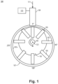
Fig. 1 is a schematic cross-sectional view of an embodiment of a pump in accordance with this disclosure, show having the rotational axis of the rotor into and out of the page; -
Fig. 2 is a schematic elevation view of an embodiment of a pump in accordance with this disclosure, shown having the rotational axis of the rotor along the plane of the page; -
Fig. 3 is a schematic elevation view of an embodiment of a pump in accordance with this disclosure, shown having the rotational axis of the rotor along the plane of the page; and -
Fig. 4 is a schematic elevation view of an embodiment of a pump in accordance with this disclosure, shown having the rotational axis of the rotor along the plane of the page. - Reference will now be made to the drawings wherein like reference numerals identify similar structural features or aspects of the subject disclosure. For purposes of explanation and illustration, and not limitation, an illustrative view of an embodiment of a pump in accordance with the disclosure is shown in
Fig. 1 and is designated generally byreference character 100. Other embodiments and/or aspects of this disclosure are shown inFigs. 2-4 . Certain embodiments described herein can be used to provide direct control of pumping action of a variable displacement pump. - In accordance with at least one aspect of this disclosure, referring to
Fig. 1 , avariable displacement pump 100 can include a rotor 101 (e.g., connected to a shaft 103) having a plurality ofvanes 105, and acam ring 107 surrounding therotor 101 andvanes 105. Thevanes 105 can be configured to extend from therotor 101 and contact aninner cam surface 107a of thecam ring 107. Thepump 100 can also include one or moreradial actuators 109 configured to apply aradial force 111 to thecam ring 107 to control a position of thecam ring 107 and the pumping action (e.g., the amount of flow/pressure produced by the pump 100). - In certain embodiments, the one or more
radial actuators 109 can be or include an electromechanical actuator (EMA), e.g., as shown inFig. 2 having anelectric motor 215 attached to the actuator 109). In certain embodiments, thepump 100 can include acontroller 113 operatively connected to and configured to directly control the one or more radial actuators 109 (e.g., themotor 215 of each radial actuator 109) to achieve a desired pumping action. - In certain embodiments, referring additionally to
Fig. 2 , thepump 100 can include one or more biasing members 217 (e.g., a spring) configured to provide anopposing force 221 to a direction of force 111 (e.g., downward as shown) applied by the one or moreradial actuators 109 to bias thecam ring 107 in a bias direction (e.g., upward as shown inFigs. 1 and2 ). In certain embodiments, the bias direction can be a maximum pumping action direction (e.g., such that failure of the one ormore actuators 109 causes maximum flow in a system, e.g., in a fuel system to ensure sufficient flow under any operational condition). In certain embodiments, thepump 100 can include analignment shaft 219 for each biasing member 217 (e.g., configured to radially align abiasing force 221 of the biasing member). - In certain embodiments, the one or more
radial actuators 109 can be configured to apply theradial force 111 in a radial direction that intersects arotational axis 123 of the rotor 101 (e.g., as shown inFigs. 1 and2 ). The one or more biasingmembers 217 can be configured to apply theopposing force 221 in an opposite direction (e.g., upward as shown) of the radial direction which also intersects therotational axis 123 of therotor 101. - In certain embodiments, e.g., as shown in the
pumps Figs. 2 and3 , the one or moreradial actuators 109 and the one or more biasingmembers 217 can be positioned on an opposite side of thecam ring 107 at 180 degrees apart. In certain embodiments, the one or moreradial actuators 109 and the one or more biasingmembers 217 can be positioned on a same side of thecam ring 107, e.g., as shown inpump 400 ofFig. 4 . - In certain embodiments, the one or more biasing
members 217 can include a plurality of biasingmembers 217 as shown inFigs. 2-4 . In certain embodiments, e.g., as shown inFig. 4 , one or more of the plurality of biasingmembers 217 can be positioned on an opposite side of thecam ring 107 at 180 degrees apart from the one or moreradial actuators 109, and one or more of the plurality of the biasingmembers 217 can be positioned on a same side of the cam ring 107 (e.g., at zero degrees) as the one or moreradial actuators 109 and can be aligned with the one or moreradial actuators 109. In certain embodiments, the one ormore alignment shafts 219 can be coincident/coaxial with one or more of the biasingmembers 217, or can be positioned spaced apart therefrom in a manner that guides thecam ring 107 and/or restrains motion of thecam ring 107 to a single axis (e.g., the vertical axis as shown), for example. - In certain embodiments, as shown in
Figs. 2-4 , the one or moreradial actuators 109 can include a plurality ofradial actuators 109. In certain embodiments, the plurality ofradial actuators 109 can be aligned axially on a single side of thecam ring 107 such that the radial force from eachradial actuator 109 passes through therotational axis 123 of therotor 101. In certain embodiments, the one or more biasingmembers 217 can include one or more biasingmembers 217 disposed between at least two of the plurality ofactuators 109 on a same side of the cam ring. 107 (e.g., as shown inFig. 4 ). Certain embodiments can utilize tension springs for same-side springs and compression springs for opposite-side springs, for example. The directionality of the one or more springs can be opposite if the directionality of the one ormore actuators 109 is opposite (e.g., tension spring on opposite side and compression spring on same side where the actuator is a pulling actuator). - In certain embodiments, the biasing force direction can be the same as the actuator force direction, e.g., to reduce actuator force required to move the
cam ring 107. In certain embodiments, the one ormore actuators 109 may release when not function causing the biasing members to push thecam ring 107 toward the maximum flow position, for example. Any other suitable relative force arrangement is contemplated herein (e.g., with force constrained to a single axis). - In accordance with at least one aspect of this disclosure, a fuel system for an aircraft (not shown) can include a variable displacement pump. The variable displacement pump can be or include any suitable pump disclosed herein, e.g., pump 100, 300, 400 as described above.
- Embodiments can include an actuator aligned with a centerline of a rotor and springs on a same side or opposite side of the cam ring. The actuators and the springs can be at any suitable angle relative to each other (e.g., provided that the cam ring is limited to a desired motion, e.g., constrained to a single axis to accurately control pumping action). Embodiments can utilize an EMA that functions independent of system pressure compared to pressure actuated systems. In embodiments, a change of the centerline of the cam ring relative to the shaft/rotor changes the displacement of the pump which changes the output flow.
- Embodiments can include an actuator applied to an outer ring of vane pump. One or more EMAs can push/pull the outer ring (e.g., the cam ring) of the vane pump to change displacement. Springs can also be incorporated by being located at either 0° or 180° locations on the outer ring depending on the travel direction that the system wants to make easier for the actuator, or to resist actuator motion. Alignment shafts/rods can also be incorporated to keep the rotor and outer ring in proper orientation. In certain embodiments, the actuator could make either the 0° or the 180° side of outer ring closer to the rotor. In certain embodiments, the actuator can include an linear variable differential transformer (LVDT) in construction to monitor position, or an LVDT external to the actuator could be included, for example. The number and/or position of springs/alignment shaft/rod can vary, depending on requirements of application, for example.
- Embodiments can include an electro-mechanically actuated variable displacement vane pump. Differential pressure across a pump might not be enough to change the displacement if the discharge pressure is too low, or sudden changes in pressure can cause other problems. Using EMAs can reduce dependence on hydromechanical forces for pump control.
- One or more EMAs can be be attached to the cam ring of a vane pump. The EMA(s) can push or pull the cam ring relative to the rotor of the pump to vary the pump's displacement. Springs can also be included in the system, attached again to the cam ring of the vane pump, either on the opposite or same side as the EMA(s), depending on the application of the pump or reducing the work of the EMA(s) in one direction. Shafts could also be included to keep the rotor and cam ring aligned. In certain embodiments, the EMA can move the cam ring such that the side of the rotor that is closer to the outer ring can switch. An LVDT can also be incorporated into the EMA to monitor position, or an external LVDT could be attached to the cam ring as well.
- Traditional variable displacement pumps use hydromechanical forces from differential pressures to change displacement. The sizing of pumps and pumping elements are also based on these forces. Using an EMA can eliminate dependence on the differential pressures so the displacement of the pump could be changed independent of pressure. This can reduce the size and weight of fuel pumps, for example, by eliminating conditions that such pumps would need to be designed to handle without EMAs.
- Embodiments (e.g., including the controller 113) can include any suitable computer hardware and/or software module(s) to perform any suitable function (e.g., as disclosed herein).
- As will be appreciated by those skilled in the art, aspects of the present disclosure may be embodied as a system, method or computer program product. Accordingly, aspects of this disclosure may take the form of an entirely hardware embodiment, an entirely software embodiment (including firmware, resident software, micro-code, etc.), or an embodiment combining software and hardware aspects, all possibilities of which can be referred to herein as a "circuit," "module," or "system." A "circuit," "module," or "system" can include one or more portions of one or more separate physical hardware and/or software components that can together perform the disclosed function of the "circuit," "module," or "system", or a "circuit," "module," or "system" can be a single self-contained unit (e.g., of hardware and/or software). Furthermore, aspects of this disclosure may take the form of a computer program product embodied in one or more computer readable medium(s) having computer readable program code embodied thereon.
- Any combination of one or more computer readable medium(s) may be utilized. The computer readable medium may be a computer readable signal medium or a computer readable storage medium. A computer readable storage medium may be, for example, but not limited to, an electronic, magnetic, optical, electromagnetic, infrared, or semiconductor system, apparatus, or device, or any suitable combination of the foregoing. More specific examples (a non-exhaustive list) of the computer readable storage medium would include the following: an electrical connection having one or more wires, a portable computer diskette, a hard disk, a random access memory (RAM), a read-only memory (ROM), an erasable programmable read-only memory (EPROM or Flash memory), an optical fiber, a portable compact disc read-only memory (CD-ROM), an optical storage device, a magnetic storage device, or any suitable combination of the foregoing. In the context of this document, a computer readable storage medium may be any tangible medium that can contain, or store a program for use by or in connection with an instruction execution system, apparatus, or device.
- A computer readable signal medium may include a propagated data signal with computer readable program code embodied therein, for example, in baseband or as part of a carrier wave. Such a propagated signal may take any of a variety of forms, including, but not limited to, electro-magnetic, optical, or any suitable combination thereof. A computer readable signal medium may be any computer readable medium that is not a computer readable storage medium and that can communicate, propagate, or transport a program for use by or in connection with an instruction execution system, apparatus, or device.
- Program code embodied on a computer readable medium may be transmitted using any appropriate medium, including but not limited to wireless, wireline, optical fiber cable, RF, etc., or any suitable combination of the foregoing.
- Computer program code for carrying out operations for aspects of this disclosure may be written in any combination of one or more programming languages, including an object oriented programming language such as Java, Smalltalk, C++ or the like and conventional procedural programming languages, such as the "C" programming language or similar programming languages. The program code may execute entirely on the user's computer, partly on the user's computer, as a stand-alone software package, partly on the user's computer and partly on a remote computer or entirely on the remote computer or server. In the latter scenario, the remote computer may be connected to the user's computer through any type of network, including a local area network (LAN) or a wide area network (WAN), or the connection may be made to an external computer (for example, through the Internet using an Internet Service Provider).
- Aspects of this disclosure may be described above with reference to flowchart illustrations and/or block diagrams of methods, apparatus (systems) and computer program products according to embodiments of this disclosure. It will be understood that each block of any flowchart illustrations and/or block diagrams, and combinations of blocks in any flowchart illustrations and/or block diagrams, can be implemented by computer program instructions. These computer program instructions may be provided to a processor of a general purpose computer, special purpose computer, or other programmable data processing apparatus to produce a machine, such that the instructions, which execute via the processor of the computer or other programmable data processing apparatus, create means for implementing the functions/acts specified in any flowchart and/or block diagram block or blocks.
- These computer program instructions may also be stored in a computer readable medium that can direct a computer, other programmable data processing apparatus, or other devices to function in a particular manner, such that the instructions stored in the computer readable medium produce an article of manufacture including instructions which implement the function/act specified in the flowchart and/or block diagram block or blocks.
- The computer program instructions may also be loaded onto a computer, other programmable data processing apparatus, or other devices to cause a series of operational steps to be performed on the computer, other programmable apparatus or other devices to produce a computer implemented process such that the instructions which execute on the computer or other programmable apparatus provide processes for implementing the functions/acts specified herein.
- Those having ordinary skill in the art understand that any numerical values disclosed herein can be exact values or can be values within a range. Further, any terms of approximation (e.g., "about", "approximately", "around") used in this disclosure can mean the stated value within a range. For example, in certain embodiments, the range can be within (plus or minus) 20%, or within 10%, or within 5%, or within 2%, or within any other suitable percentage or number as appreciated by those having ordinary skill in the art (e.g., for known tolerance limits or error ranges).
- The articles "a", "an", and "the" as used herein and in the appended claims are used herein to refer to one or to more than one (i.e., to at least one) of the grammatical object of the article unless the context clearly indicates otherwise. By way of example, "an element" means one element or more than one element.
- The phrase "and/or," as used herein in the specification and in the claims, should be understood to mean "either or both" of the elements so conjoined, i.e., elements that are conjunctively present in some cases and disjunctively present in other cases. Multiple elements listed with "and/or" should be construed in the same fashion, i.e., "one or more" of the elements so conjoined. Other elements may optionally be present other than the elements specifically identified by the "and/or" clause, whether related or unrelated to those elements specifically identified. Thus, as a non-limiting example, a reference to "A and/or B", when used in conjunction with open-ended language such as "comprising" can refer, in one embodiment, to A only (optionally including elements other than B); in another embodiment, to B only (optionally including elements other than A); in yet another embodiment, to both A and B (optionally including other elements); etc.
- As used herein in the specification and in the claims, "or" should be understood to have the same meaning as "and/or" as defined above. For example, when separating items in a list, "or" or "and/or" shall be interpreted as being inclusive, i.e., the inclusion of at least one, but also including more than one, of a number or list of elements, and, optionally, additional unlisted items. Only terms clearly indicated to the contrary, such as "only one of' or "exactly one of," or, when used in the claims, "consisting of," will refer to the inclusion of exactly one element of a number or list of elements. In general, the term "or" as used herein shall only be interpreted as indicating exclusive alternatives (i.e., "one or the other but not both") when preceded by terms of exclusivity, such as "either," "one of," "only one of," or "exactly one of."
- Any suitable combination(s) of any disclosed embodiments and/or any suitable portion(s) thereof are contemplated herein as appreciated by those having ordinary skill in the art in view of this disclosure.
- The embodiments of the present disclosure, as described above and shown in the drawings, provide for improvement in the art to which they pertain.
Claims (15)
- A variable displacement pump, comprising:a rotor (101) having a plurality of vanes (105);a cam ring (107) surrounding the rotor and vanes, the vanes configured to extend from the rotor and contact an inner cam surface (107a) of the cam ring; andone or more radial actuators (109) configured to apply a radial force to the cam ring to control a position of the cam ring and the pumping action.
- The pump of claim 1, wherein the one or more radial actuators (109) are or include an electromechanical actuator; and/or the pump further comprising a controller (113) configured to directly control the one or more radial actuators to achieve a desired pumping action.
- The pump of claim 1 or 2, further comprising one or more biasing members (217) configured to provide an opposing force to a direction of force applied by the one or more radial actuators (109) to bias the cam ring (107) in a bias direction.
- The pump of claim 3, wherein the bias direction is a maximum pumping action direction; and/or the pump further comprising an alignment shaft (219) for each biasing member (217).
- The pump of claim 3 or 4, wherein the one or more radial actuators (109) are configured to apply the radial force in a radial direction that intersects a rotational axis (123) of the rotor (101), and the one or more biasing members (217) are configured to apply the opposing force in an opposite direction of the radial direction which also intersects the rotational axis of the rotor.
- The pump of claim 5, wherein the one or more radial actuators (109) and the one or more biasing members (217) are positioned on an opposite side of the cam ring (107) 180 degrees apart; or wherein the one or more radial actuators and the one or more biasing members are positioned on a same side of the cam ring.
- The pump of claim 5 or 6, wherein the one or more biasing members (217) includes a plurality of biasing members; and optionally wherein one or more of the plurality of biasing members are positioned on an opposite side of the cam ring (107) 180 degrees apart from the one or more radial actuators (109), and wherein one or more of the plurality of the biasing members are positioned on a same side of the cam ring as the one or more radial actuators and are aligned with the one or more radial actuators.
- The pump of claim 5, 6 or 7, wherein the one or more radial actuators (109) include a plurality of radial actuators.
- The pump of claim 8, wherein the plurality of radial actuators (109) are aligned axially on a single side of the cam ring (107) such that the radial force from each radial actuator passes through the rotational axis (123) of the rotor (101).
- The pump of claim 8 or 9, wherein the one or more biasing members (217) includes one or more biasing members disposed between at least two of the plurality of actuators (109) on a same side of the cam ring (107).
- A fuel system for an aircraft, comprising:
a variable displacement pump (100), comprising:a rotor (101) having a plurality of vanes (105);a cam ring (107) surrounding the rotor and vanes, the vanes configured to extend from the rotor and contact an inner cam surface (107a) of the cam ring; andone or more radial actuators (109) configured to apply a radial force to the cam ring to control a position of the cam ring and the pumping action. - The system of claim 11, wherein the one or more radial actuators (109) are or include an electromechanical actuator; and/or the system further comprising a controller (113) configured to directly control the one or more radial actuators (109) to achieve a desired pumping action.
- The system of claim 11 or 12, further comprising one or more biasing members (217) configured to provide an opposing force to a direction of force applied by the one or more radial actuators (109) to bias the cam ring (107) in a bias direction.
- The system of claim 11, 12 or 13, wherein the bias direction is a maximum pumping action direction.
- The system of claim 11, 12, 13 or 14, further comprising an alignment shaft (219) for each biasing member (217).
Applications Claiming Priority (1)
| Application Number | Priority Date | Filing Date | Title |
|---|---|---|---|
| US18/201,039 US20240392780A1 (en) | 2023-05-23 | 2023-05-23 | Variable displacement pump systems |
Publications (1)
| Publication Number | Publication Date |
|---|---|
| EP4467811A1 true EP4467811A1 (en) | 2024-11-27 |
Family
ID=91226885
Family Applications (1)
| Application Number | Title | Priority Date | Filing Date |
|---|---|---|---|
| EP24177440.5A Pending EP4467811A1 (en) | 2023-05-23 | 2024-05-22 | Variable displacement pump systems |
Country Status (2)
| Country | Link |
|---|---|
| US (1) | US20240392780A1 (en) |
| EP (1) | EP4467811A1 (en) |
Citations (7)
| Publication number | Priority date | Publication date | Assignee | Title |
|---|---|---|---|---|
| US2451279A (en) * | 1944-08-04 | 1948-10-12 | Gilbert & Barker Mfg Co | Variable capacity vane pump for oil burners |
| JPH0544657A (en) * | 1991-08-20 | 1993-02-23 | Sanwa Seiki Co Ltd | Control of displacement volume of vane pump |
| US20090324438A1 (en) * | 2008-06-26 | 2009-12-31 | Hamilton Sundstrand Corporation | Variable flow pumping system |
| CA2753511A1 (en) * | 2009-03-05 | 2010-09-10 | Stt Technologies Inc., A Joint Venture Of Magna Powertrain Inc. And Shw Gmbh | Direct control linear variable displacement vane pump |
| DE102011004649A1 (en) * | 2011-02-24 | 2012-08-30 | Robert Bosch Gmbh | Fuel delivery device and method for actuating a fuel delivery device |
| CN103363279B (en) * | 2012-04-05 | 2016-09-07 | 同济大学 | A kind of vane type stepless variable lubricating oil pump of step motor control |
| EP4123177A1 (en) * | 2021-07-23 | 2023-01-25 | Hamilton Sundstrand Corporation | Variable displacement pump systems with direct actuation |
Family Cites Families (5)
| Publication number | Priority date | Publication date | Assignee | Title |
|---|---|---|---|---|
| US3070020A (en) * | 1958-07-18 | 1962-12-25 | Gen Motors Corp | Variable displacement pumping mechanism |
| US3359761A (en) * | 1965-12-13 | 1967-12-26 | Borg Warner | Hydraulic transmission |
| US20070224067A1 (en) * | 2006-03-27 | 2007-09-27 | Manfred Arnold | Variable displacement sliding vane pump |
| US9845007B2 (en) * | 2014-02-10 | 2017-12-19 | Honda Motor Co., Ltd. | Driving force distributing device |
| DE102017106546A1 (en) * | 2017-03-27 | 2018-09-27 | Robert Bosch Gmbh | Oil pump with electrically adjustable displacement |
-
2023
- 2023-05-23 US US18/201,039 patent/US20240392780A1/en not_active Abandoned
-
2024
- 2024-05-22 EP EP24177440.5A patent/EP4467811A1/en active Pending
Patent Citations (7)
| Publication number | Priority date | Publication date | Assignee | Title |
|---|---|---|---|---|
| US2451279A (en) * | 1944-08-04 | 1948-10-12 | Gilbert & Barker Mfg Co | Variable capacity vane pump for oil burners |
| JPH0544657A (en) * | 1991-08-20 | 1993-02-23 | Sanwa Seiki Co Ltd | Control of displacement volume of vane pump |
| US20090324438A1 (en) * | 2008-06-26 | 2009-12-31 | Hamilton Sundstrand Corporation | Variable flow pumping system |
| CA2753511A1 (en) * | 2009-03-05 | 2010-09-10 | Stt Technologies Inc., A Joint Venture Of Magna Powertrain Inc. And Shw Gmbh | Direct control linear variable displacement vane pump |
| DE102011004649A1 (en) * | 2011-02-24 | 2012-08-30 | Robert Bosch Gmbh | Fuel delivery device and method for actuating a fuel delivery device |
| CN103363279B (en) * | 2012-04-05 | 2016-09-07 | 同济大学 | A kind of vane type stepless variable lubricating oil pump of step motor control |
| EP4123177A1 (en) * | 2021-07-23 | 2023-01-25 | Hamilton Sundstrand Corporation | Variable displacement pump systems with direct actuation |
Also Published As
| Publication number | Publication date |
|---|---|
| US20240392780A1 (en) | 2024-11-28 |
Similar Documents
| Publication | Publication Date | Title |
|---|---|---|
| EP3431717B1 (en) | Method and configuration for improved variable vane positioning | |
| DE2349033C3 (en) | Turbo molecular pump | |
| EP3291427B1 (en) | Active-active redundant motor gear system | |
| EP2911275B1 (en) | A modular motor and magnetic bearing assembly, and a manufacturing method therefor | |
| EP3667047B1 (en) | Fuel systems having reduced bypass flow | |
| US9783290B2 (en) | Jam-tolerant rotary control motor for hydraulic actuator valve | |
| EP4209680B1 (en) | Fuel pump systems | |
| US20140112774A1 (en) | Centrifugal gas compressor magnetic bearing thrust collar with mounting pilots | |
| GB2285098A (en) | Propeller pitch change mechanism with inductive brake and motor | |
| US10167732B2 (en) | Passive overspeed controlled turbo pump assembly | |
| EP2770223B1 (en) | A machine provided with safety bearing | |
| EP4123177A1 (en) | Variable displacement pump systems with direct actuation | |
| US10560011B2 (en) | Linear electromechanical actuators | |
| US20170306773A1 (en) | Simplified pitch actuation system for a turbine engine propeller | |
| US20240392780A1 (en) | Variable displacement pump systems | |
| US10870481B2 (en) | Pitch actuation system for a turbomachine propeller | |
| WO2018063820A1 (en) | Turbomachine with active magnetic bearings | |
| US11124287B2 (en) | Fan module with variable-pitch blades for a turbomachine | |
| US9464533B2 (en) | Compact IGV for turboexpander application | |
| EP4160011A1 (en) | Variable positive displacement pump actuator systems | |
| US10647411B2 (en) | Electromechanical pitch actuation system for a turbomachine propeller | |
| US12331740B2 (en) | Variable displacement pumps | |
| CN110714984A (en) | A magnetic suspension bearing axial displacement automatic stabilization device and stabilization method | |
| CN205029540U (en) | Super separation and reunion permanent magnetism speed regulator | |
| AU2012100759A4 (en) | An Armature |
Legal Events
| Date | Code | Title | Description |
|---|---|---|---|
| PUAI | Public reference made under article 153(3) epc to a published international application that has entered the european phase |
Free format text: ORIGINAL CODE: 0009012 |
|
| STAA | Information on the status of an ep patent application or granted ep patent |
Free format text: STATUS: THE APPLICATION HAS BEEN PUBLISHED |
|
| AK | Designated contracting states |
Kind code of ref document: A1 Designated state(s): AL AT BE BG CH CY CZ DE DK EE ES FI FR GB GR HR HU IE IS IT LI LT LU LV MC ME MK MT NL NO PL PT RO RS SE SI SK SM TR |
|
| STAA | Information on the status of an ep patent application or granted ep patent |
Free format text: STATUS: REQUEST FOR EXAMINATION WAS MADE |
|
| 17P | Request for examination filed |
Effective date: 20250526 |
|
| STAA | Information on the status of an ep patent application or granted ep patent |
Free format text: STATUS: EXAMINATION IS IN PROGRESS |
|
| 17Q | First examination report despatched |
Effective date: 20251010 |