EP4467775A1 - Kinetische energie absorbierender verbundartikel - Google Patents
Kinetische energie absorbierender verbundartikel Download PDFInfo
- Publication number
- EP4467775A1 EP4467775A1 EP24173264.3A EP24173264A EP4467775A1 EP 4467775 A1 EP4467775 A1 EP 4467775A1 EP 24173264 A EP24173264 A EP 24173264A EP 4467775 A1 EP4467775 A1 EP 4467775A1
- Authority
- EP
- European Patent Office
- Prior art keywords
- pattern
- localised
- sub
- kinetic energy
- composite article
- Prior art date
- Legal status (The legal status is an assumption and is not a legal conclusion. Google has not performed a legal analysis and makes no representation as to the accuracy of the status listed.)
- Pending
Links
Images


Classifications
-
- F—MECHANICAL ENGINEERING; LIGHTING; HEATING; WEAPONS; BLASTING
- F16—ENGINEERING ELEMENTS AND UNITS; GENERAL MEASURES FOR PRODUCING AND MAINTAINING EFFECTIVE FUNCTIONING OF MACHINES OR INSTALLATIONS; THERMAL INSULATION IN GENERAL
- F16F—SPRINGS; SHOCK-ABSORBERS; MEANS FOR DAMPING VIBRATION
- F16F7/00—Vibration-dampers; Shock-absorbers
- F16F7/003—One-shot shock absorbers
-
- F—MECHANICAL ENGINEERING; LIGHTING; HEATING; WEAPONS; BLASTING
- F01—MACHINES OR ENGINES IN GENERAL; ENGINE PLANTS IN GENERAL; STEAM ENGINES
- F01D—NON-POSITIVE DISPLACEMENT MACHINES OR ENGINES, e.g. STEAM TURBINES
- F01D21/00—Shutting-down of machines or engines, e.g. in emergency; Regulating, controlling, or safety means not otherwise provided for
- F01D21/04—Shutting-down of machines or engines, e.g. in emergency; Regulating, controlling, or safety means not otherwise provided for responsive to undesired position of rotor relative to stator or to breaking-off of a part of the rotor, e.g. indicating such position
- F01D21/045—Shutting-down of machines or engines, e.g. in emergency; Regulating, controlling, or safety means not otherwise provided for responsive to undesired position of rotor relative to stator or to breaking-off of a part of the rotor, e.g. indicating such position special arrangements in stators or in rotors dealing with breaking-off of part of rotor
-
- F—MECHANICAL ENGINEERING; LIGHTING; HEATING; WEAPONS; BLASTING
- F01—MACHINES OR ENGINES IN GENERAL; ENGINE PLANTS IN GENERAL; STEAM ENGINES
- F01D—NON-POSITIVE DISPLACEMENT MACHINES OR ENGINES, e.g. STEAM TURBINES
- F01D21/00—Shutting-down of machines or engines, e.g. in emergency; Regulating, controlling, or safety means not otherwise provided for
- F01D21/04—Shutting-down of machines or engines, e.g. in emergency; Regulating, controlling, or safety means not otherwise provided for responsive to undesired position of rotor relative to stator or to breaking-off of a part of the rotor, e.g. indicating such position
-
- F—MECHANICAL ENGINEERING; LIGHTING; HEATING; WEAPONS; BLASTING
- F01—MACHINES OR ENGINES IN GENERAL; ENGINE PLANTS IN GENERAL; STEAM ENGINES
- F01D—NON-POSITIVE DISPLACEMENT MACHINES OR ENGINES, e.g. STEAM TURBINES
- F01D5/00—Blades; Blade-carrying members; Heating, heat-insulating, cooling or antivibration means on the blades or the members
- F01D5/12—Blades
- F01D5/14—Form or construction
- F01D5/147—Construction, i.e. structural features, e.g. of weight-saving hollow blades
-
- F—MECHANICAL ENGINEERING; LIGHTING; HEATING; WEAPONS; BLASTING
- F01—MACHINES OR ENGINES IN GENERAL; ENGINE PLANTS IN GENERAL; STEAM ENGINES
- F01D—NON-POSITIVE DISPLACEMENT MACHINES OR ENGINES, e.g. STEAM TURBINES
- F01D5/00—Blades; Blade-carrying members; Heating, heat-insulating, cooling or antivibration means on the blades or the members
- F01D5/12—Blades
- F01D5/28—Selecting particular materials; Particular measures relating thereto; Measures against erosion or corrosion
- F01D5/282—Selecting composite materials, e.g. blades with reinforcing filaments
-
- F—MECHANICAL ENGINEERING; LIGHTING; HEATING; WEAPONS; BLASTING
- F05—INDEXING SCHEMES RELATING TO ENGINES OR PUMPS IN VARIOUS SUBCLASSES OF CLASSES F01-F04
- F05D—INDEXING SCHEME FOR ASPECTS RELATING TO NON-POSITIVE-DISPLACEMENT MACHINES OR ENGINES, GAS-TURBINES OR JET-PROPULSION PLANTS
- F05D2220/00—Application
- F05D2220/30—Application in turbines
- F05D2220/32—Application in turbines in gas turbines
-
- F—MECHANICAL ENGINEERING; LIGHTING; HEATING; WEAPONS; BLASTING
- F05—INDEXING SCHEMES RELATING TO ENGINES OR PUMPS IN VARIOUS SUBCLASSES OF CLASSES F01-F04
- F05D—INDEXING SCHEME FOR ASPECTS RELATING TO NON-POSITIVE-DISPLACEMENT MACHINES OR ENGINES, GAS-TURBINES OR JET-PROPULSION PLANTS
- F05D2220/00—Application
- F05D2220/30—Application in turbines
- F05D2220/36—Application in turbines specially adapted for the fan of turbofan engines
-
- F—MECHANICAL ENGINEERING; LIGHTING; HEATING; WEAPONS; BLASTING
- F05—INDEXING SCHEMES RELATING TO ENGINES OR PUMPS IN VARIOUS SUBCLASSES OF CLASSES F01-F04
- F05D—INDEXING SCHEME FOR ASPECTS RELATING TO NON-POSITIVE-DISPLACEMENT MACHINES OR ENGINES, GAS-TURBINES OR JET-PROPULSION PLANTS
- F05D2230/00—Manufacture
- F05D2230/50—Building or constructing in particular ways
-
- F—MECHANICAL ENGINEERING; LIGHTING; HEATING; WEAPONS; BLASTING
- F05—INDEXING SCHEMES RELATING TO ENGINES OR PUMPS IN VARIOUS SUBCLASSES OF CLASSES F01-F04
- F05D—INDEXING SCHEME FOR ASPECTS RELATING TO NON-POSITIVE-DISPLACEMENT MACHINES OR ENGINES, GAS-TURBINES OR JET-PROPULSION PLANTS
- F05D2230/00—Manufacture
- F05D2230/90—Coating; Surface treatment
-
- F—MECHANICAL ENGINEERING; LIGHTING; HEATING; WEAPONS; BLASTING
- F05—INDEXING SCHEMES RELATING TO ENGINES OR PUMPS IN VARIOUS SUBCLASSES OF CLASSES F01-F04
- F05D—INDEXING SCHEME FOR ASPECTS RELATING TO NON-POSITIVE-DISPLACEMENT MACHINES OR ENGINES, GAS-TURBINES OR JET-PROPULSION PLANTS
- F05D2260/00—Function
- F05D2260/96—Preventing, counteracting or reducing vibration or noise
-
- F—MECHANICAL ENGINEERING; LIGHTING; HEATING; WEAPONS; BLASTING
- F05—INDEXING SCHEMES RELATING TO ENGINES OR PUMPS IN VARIOUS SUBCLASSES OF CLASSES F01-F04
- F05D—INDEXING SCHEME FOR ASPECTS RELATING TO NON-POSITIVE-DISPLACEMENT MACHINES OR ENGINES, GAS-TURBINES OR JET-PROPULSION PLANTS
- F05D2300/00—Materials; Properties thereof
- F05D2300/60—Properties or characteristics given to material by treatment or manufacturing
- F05D2300/603—Composites; e.g. fibre-reinforced
-
- F—MECHANICAL ENGINEERING; LIGHTING; HEATING; WEAPONS; BLASTING
- F16—ENGINEERING ELEMENTS AND UNITS; GENERAL MEASURES FOR PRODUCING AND MAINTAINING EFFECTIVE FUNCTIONING OF MACHINES OR INSTALLATIONS; THERMAL INSULATION IN GENERAL
- F16F—SPRINGS; SHOCK-ABSORBERS; MEANS FOR DAMPING VIBRATION
- F16F2224/00—Materials; Material properties
- F16F2224/02—Materials; Material properties solids
- F16F2224/0241—Fibre-reinforced plastics [FRP]
-
- F—MECHANICAL ENGINEERING; LIGHTING; HEATING; WEAPONS; BLASTING
- F16—ENGINEERING ELEMENTS AND UNITS; GENERAL MEASURES FOR PRODUCING AND MAINTAINING EFFECTIVE FUNCTIONING OF MACHINES OR INSTALLATIONS; THERMAL INSULATION IN GENERAL
- F16F—SPRINGS; SHOCK-ABSORBERS; MEANS FOR DAMPING VIBRATION
- F16F2230/00—Purpose; Design features
- F16F2230/0023—Purpose; Design features protective
-
- Y—GENERAL TAGGING OF NEW TECHNOLOGICAL DEVELOPMENTS; GENERAL TAGGING OF CROSS-SECTIONAL TECHNOLOGIES SPANNING OVER SEVERAL SECTIONS OF THE IPC; TECHNICAL SUBJECTS COVERED BY FORMER USPC CROSS-REFERENCE ART COLLECTIONS [XRACs] AND DIGESTS
- Y02—TECHNOLOGIES OR APPLICATIONS FOR MITIGATION OR ADAPTATION AGAINST CLIMATE CHANGE
- Y02T—CLIMATE CHANGE MITIGATION TECHNOLOGIES RELATED TO TRANSPORTATION
- Y02T50/00—Aeronautics or air transport
- Y02T50/60—Efficient propulsion technologies, e.g. for aircraft
Definitions
- the present disclosure concerns a kinetic energy absorptive composite article that if it fails in use it will fail in a safe and controlled manner.
- the kinetic energy absorptive composite article may be a gas turbine engine composite fan blade that if it is damaged by a bird strike will fail in a controlled manner such that the fan blade or any portion thereof will remain located within the engine and the impact energy will be safely dissipated.
- Gas turbine engines used for aerospace propulsion are typically designed for safe operation if a bird strikes one of the fan blades with sufficient force to cause the fan blade, or a portion thereof, to break off the fan.
- gas turbine engines typically comprise fan containment systems that surround the fan blades of the fan. These systems are often heavy, with the mass of the fan containment system correlating to the kinetic energy of the released fan blade or portion of fan blade that is to be contained.
- a kinetic energy absorptive composite article comprising a plurality of plies. Each ply comprises a plurality of substantially parallel fibers and a resin encapsulating the plurality of fibers. A plurality of localised weaknesses are comprised within the fibers, the locations of the plurality of localised weaknesses forming a pre-defined pattern.
- the pre-defined pattern comprises a first sub-pattern and a second sub-pattern superposed upon the first sub-pattern.
- the first sub-pattern is configured so that a crack formed by an impact event propagates substantially along a pre-determined fracture path to separate the kinetic energy absorptive composite article into at least a first portion and a second portion.
- the second sub-pattern is configured to set a threshold below which the crack does not propagate.
- a gas turbine engine that includes a kinetic energy absorptive composite article of the first aspect.
- a method for manufacturing a kinetic energy absorptive composite article that will fail in a controlled manner upon impact comprising the steps of laying up a ply and introducing at least one localised weakness to the ply in dependence upon a record of the required location of the at least one localised weakness.
- the principle of providing a kinetic energy absorptive composite article that is configured to fracture along a pre-defined surface once an impact threshold is exceeded may also be incorporated in other applications, in which a body or exterior body panel of vehicle comprises a composite structure.
- the body or exterior panel of the vehicle may fracture in a controlled manner. This may ease repair of the body or exterior panel, as repair pieces, of a known shape, may be prepared and made available for vehicle repair, following the vehicle being involved in an accident.
- localised weakness defines a feature that is deliberately introduced within a composite ply to promote failure of the composite laminate at or in proximity of the localised weakness.
- a localised weakness may therefore be distinguished from a weakness within a composite structure arising from manufacturing variability of the laminate or the components (fiber, resin) from which the composite laminate is manufactured.
- alternative release plane is defined as a plane that separates a released portion of a fan blade from a retained portion of the fan blade under Fan Blade Off (FBO) conditions, the alternative release plane being radially-outboard of a retaining means used to retain a composite fan blade 31 by a feature of a fan disc and radially outboard of an annulus line formed by an intersection of a surface of the fan blade and the exterior profile of a fan spinner.
- FBO Fan Blade Off
- an alternative release plane is differentiated from a conventional release plane, as a conventional release plane is at or inboard of the annulus line.
- a gas turbine engine is generally indicated at 10, having a principal and rotational axis 11.
- the engine 10 comprises, in axial flow series, an air intake 12, a propulsive fan 13, an intermediate pressure compressor 14, a high-pressure compressor 15, combustion equipment 16, a high-pressure turbine 17, an intermediate pressure turbine 18, a low-pressure turbine 19 and an exhaust nozzle 20.
- a nacelle 21 generally surrounds the engine 10 and defines both the intake 12 and the exhaust nozzle 20.
- the gas turbine engine 10 works in the conventional manner so that air entering the intake 12 is accelerated by the fan 13 to produce two air flows: a first air flow into the intermediate pressure compressor 14 and a second air flow which passes through a bypass duct 22 to provide propulsive thrust.
- the intermediate pressure compressor 14 compresses the air flow directed into it before delivering that air to the high pressure compressor 15 where further compression takes place.
- the compressed air exhausted from the high-pressure compressor 15 is directed into the combustion equipment 16 where it is mixed with fuel and the mixture combusted.
- the resultant hot combustion products then expand through, and thereby drive the high, intermediate and low-pressure turbines 17, 18, 19 before being exhausted through the nozzle 20 to provide additional propulsive thrust.
- the high 17, intermediate 18 and low 19 pressure turbines drive respectively the high pressure compressor 15, intermediate pressure compressor 14 and fan 13, each by suitable interconnecting shaft.
- gas turbine engines to which the present disclosure may be applied may have alternative configurations.
- such engines may have an alternative number of interconnecting shafts (e.g. two) and/or an alternative number of compressors and/or turbines.
- the engine may comprise a gearbox provided in the drive train from a turbine to a compressor and/or fan.
- the gas turbine engine 10 may be designed to safely accommodate certain identified engine failure scenarios. Indeed, the ability of the gas turbine engine 10 to accommodate certain identified failure scenarios, may be mandatory if the gas turbine engine 10 is to be cleared by a certification authority such as the European Union Aviation Safety Authority (EASA) or Federal Aviation Authority (FAA), for transporting passengers.
- EASA European Union Aviation Safety Authority
- FAA Federal Aviation Authority
- FBO Fan Blade Off
- the released portion of the at least one fan blade impacts components of the fan case 32 surrounding the fan 13.
- the components impacted may form a fan containment system, as they are configured to contain the portion of the at least one fan blade 31 following its release.
- the fan containment system may be any form of fan containment system.
- the fan containment system may comprise an aramid composite, such as a composite comprising Kevlar ® , that is repeatedly wrapped around an outer perimeter of a fan case that surrounds fan 13.
- a portion from a single fan blade 31 may be released.
- a portion from a plurality of fan blades 31 may be released.
- release of a portion from a first fan blade 31 may cause the release of a portion from a second fan blade 31 that is adjacent to the first fan blade, if the released portion of the first fan blade 31 impacts the second fan blade 31 during the Fan Blade Off event.
- the second fan blade may be referred to as a trailing blade as it trails (follows) the first fan blade 31, when account is made for the direction of rotation of the fan 13 and fan blades 31.
- kinetic energy possessed by a released portion of a fan blade correlates to the mass of the released portion and the square of the rotational speed of the fan 13 at the time at which the portion of the fan blade 31 is released.
- the mass of the fan containment system therefore also correlates to the mass of the released portion of the fan blade 31 that is to be contained by the fan containment system.
- the fan containment system may have a large radius and be relatively heavy.
- the fan containment system provides no functional benefit for the gas turbine engine 10, other than during a fan blade off event, which is a statistically unlikely event.
- an aircraft propelled by the gas turbine engine 10 carries mass (the mass of the fan containment system) to mitigate against the effect of an event which may never occur during the operational lifetime of a specific aircraft.
- Reducing the mass of the released portion of the first fan blade 31, or second fan blade 31 is therefore desirable, as it permits the mass of the fan containment system to be reduced.
- This provides a benefit to an aircraft to which the gas turbine engine 10 is fitted, as the mass of the aircraft, comprising the at least one gas turbine engine 10 is reduced. This reduces the fuel consumption of the aircraft and may permit the aircraft to carry an additional passenger or passengers, increasing the revenue for an airline that operates the aircraft.
- the mass of the fan blade or portion of the fan blade released during a fan blade off event also directly influences the magnitude of out of balance forcing caused by the continued rotation of a fan 13 that has shed a blade or portion of a fan blade.
- the ability of a gas turbine engine 10 to tolerate continued out of balance forcing following a Fan Blade Off event may also be required, as the fan 13 may continue to rotate for several hours once an engine10 has been shut down, due to the forward speed of an aircraft on which the engine is mounted and the fact that the aircraft may be several hours flying time away from an airport at the time at which the fan blade off event occurs. This may be the case, if for example, the aircraft is crossing an ocean at the time at which the fan blade off event occurs.
- Reducing the mass of the released portion of fan blade 31 may therefore have the additional benefit that it may also permit lighter-weight structural features to be incorporated within the engine, leading to further savings in total engine mass.
- the separation surface it would be desirable for separation of the fan blade into a released portion and a retained portion to occur at a mean blade height that is radially outboard of the blade height at which separation may typically be expected to occur (for example, such as along an annulus line 35 - see FIG. 2 ). It would also be desirable for the separation surface to be substantially repeatable for the same blade geometry, such that separation along this surface may be reliably assumed during fan containment events. This surface, as it is outboard of annulus line 35, may be referred to as an alternative release plane 33a.
- the alternative release plane 33a substantially corresponds to a pre-defined fracture surface 33b, as it defines the direction of propagation of at least one crack 40 within the fan blade 31 in a pre-defined direction.
- the pre-defined fracture surface 33b may meander about the alternative release plane 33a, meaning that the pre-defined fracture surface 33b may not be identical to the alternative release plane 33a.
- Fracture along the pre-defined fracture surface 33b reduces variability in the magnitude of the released portion of a fan blade under fan blade off conditions.
- FIG. 2 provides an illustration of a composite fan blade 31.
- a plurality of example alternative release planes 33a are also shown in the FIG.
- the composite fan blade predominantly comprises a composite laminate 39 comprising a plurality of different layers (plies) of fiber material, encapsulated within a resin.
- the plies may each comprise a plurality of parallel fibers with a resin to form a composite laminate 39, as is known in the art.
- the orientation of the fibers of adjacent, overlaying plies may be the same or different.
- the composite fan blade 31 additionally comprises reinforced regions, at the leading edge and trailing edge of the blade.
- the reinforced regions (comprising fan blade leading edge reinforcement 37 and fan blade trailing edge reinforcement 38) may be reinforced by a metallic shield over the leading edge or trailing edge of the composite portion of the fan blade 31.
- composite fan blades 31 may comprise metallic reinforcement at the leading edge and/or trailing edge.
- the composite fan blade 31 of FIG. 2 is an example of a kinetic energy absorptive composite article 31.
- an alternative release plane 33a (i.e., corresponding to a pre-defined fracture surface 33b) within a co-ordinate system, such as a cartesian co-ordinate system or a cylindrical polar co-ordinate system, may extend in two dimensions (for example, constant in a radial direction) or may extend in three dimensions.
- the blade may respond and/or oscillate in a modal shape or superposition of a plurality of modal shapes.
- the at least one modal shape may define areas of the blade with greater strain and /or displacement.
- the at least one modal shape may have a frequency of oscillation.
- the fan blade 31 When, following impact, the fan blade 31 responds and /or oscillates with a modal shape, localised areas of higher strain and higher stress may be created or accentuated within the fan blade, relative to the stress and strains within the fan blade prior to impact (equilibrium conditions).
- the modal shape of the fan blade, and the stresses and strains within the fan blade may be simulated by numerical analytical techniques such as finite element analysis. Thus, it is possible to predict the likely behaviour of the fan blade under impact conditions. This may be beneficial during the design of the arrangement of plies that form the composite blade.
- the composite material from which the gas turbine engine fan blade 31 is made is stiff and can sustain high loads, if the local strain capability of the composite fibers and/or interface between composite fibers and resin is exceeded, localised breakage of the composite fiber and/or composite resin in which the composite fiber is encompassed, may occur, forming a crack 40. Forming the crack 40 releases stored strain energy within the vicinity of the tip of the crack, due to a reduction in strain proximal to the tip of the crack 40.
- the crack will propagate.
- the crack propagates in a direction to reduce the elastic energy (strain energy) stored within the fan blade.
- Variations in at least one of the impact location, impact energy, and/or composition of the composite laminate due to manufacturing variability may influence the direction of crack propagation.
- FIGS. 3 and 4 provide an illustrative example of how this variation in impact or manufacturing may be accommodated, by disclosing a pattern 41a for producing predictable crack propagation along an alternative release plane 33a corresponding to a pre-defined fracture surface 33b and avoiding the disadvantages of known alternative release plane methods such as a non-optimised aerodynamic shape, increase in blade mass or reduction in blade strength.
- pre-defined fracture surfaces 33b corresponding to a pre-defined patterns 41a different to those shown in FIGS. 3 and 4 may also be envisaged.
- a pre-defined fracture surface 33b may be aligned with any one of the example alternative release planes 33a illustrated in FIG. 2 .
- the composite laminate comprises a plurality of overlaying plies comprising fibers encased within a resin.
- the composite laminate additionally comprises a plurality of localised weaknesses 42.
- FIG. 3 and FIG. 4 are marked with a three-dimensional co-ordinate system.
- X is a chordal direction, aligned along the blade at constant radius
- R is aligned in a radial direction that is orthogonal to "X”
- T is in a direction of thru-thickness of the blade.
- T is orthogonal to both "R” and an exterior surface of the fan blade at which the cross-section of FIG. 4 is made. It will be appreciated that as the fan blade may be twisted (for example, to provide an aerodynamic benefit), "T” may or may not be orthogonal to "X” at a specific cross-section.
- FIG. 3 is a plan view of a portion of a ply 50 in the laminate which forms the kinetic energy absorptive composite article 31 such as a fan blade 31.
- the ply 50 comprises a ply pre-defined pattern 41a, lying in the plane of the ply 50.
- the ply pre-defined pattern 41a comprises at least one localised weakness 42.
- the at least one localised weakness 42 may be formed by severing or partially severing a fiber of the ply 50, or a grouping of a plurality of fibers of the ply 50.
- the ply pre-defined pattern 41a may be regarded as a two-dimensional pattern, even though the ply may be curved in cartesian space.
- the laminate which forms the kinetic energy absorptive composite article comprises a plurality of overlaying plies
- the laminate which forms the kinetic energy absorptive composite article therefore comprises a plurality of overlaying ply pre-defined patterns 41a.
- the summation of the plurality of two-dimensional ply pre-defined patterns 41a of the ply layers forms a pre-defined pattern 41b.
- the pre-defined pattern 41b may be regarded as a three-dimensional pattern.
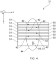
- FIG. 4 is a cross-sectional view through the laminate which forms the kinetic energy absorptive composite article 31.
- plies 50 which extend across the thickness of the kinetic energy absorptive composite article 31 comprise at least one localised weakness 42, and as a consequence, comprise a ply pre-defined pattern 41a, an example of which is illustrated in FIG. 3 .
- plies 50 comprising at least one localised weakness 42 are shown interleaved with plies 51 that do not comprise at least one localised weakness 42, other overlaying arrangements of plies 50,51 are possible depending upon the nature of the desired pre-defined pattern 41b.
- each ply within the composite laminate may comprise at least one localised weakness.
- At least one localised weakness 42 may extend across a plurality of plies 50.
- the size of the localised weakness for example, by extending across a plurality of fibers within a ply and/or a plurality of fibers spanning adjacent plies, the propagation of a crack 40 within the laminate may be controlled.
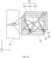
- pre-defined pattern 41b and its associated crack propagation, may be further understood by reference to FIG. 5 .
- FIG. 5 illustrates an example arrangement of sequentially overlaying ply layers 50', 50", 50′′′ and 51 which form part of a laminate.
- Ply layer 50' overlays ply layer 50" and comprises ply pre-defined pattern 41 a';
- Ply layer 50" is between ply layer 50' and ply layer 50′′′, and comprised ply pre-defined pattern 41a";
- Ply layer 50′′′ is between ply layers 50" and ply layer 51', and comprises ply pre-defined pattern 41a′′′;
- Ply layer 51' is overlaid by ply layer 50′′′ and does not comprise a ply pre-defined pattern.
- the orientation of fiber lay-up may vary between ply-layers.
- adjacent orientations of 45°, 0°, -45°, 90° are used.
- Fiber orientations may also be used.
- ply orientations of -60°, 0°, 60° may be used, as may helicoidal ply layups, in which the fiber orientation angle between adjacent plies is less than 30°.
- the orientation of the ply pre-defined pattern 41a within a ply 50 is influenced by the orientation of the fibers within that ply 50.
- the orientation of overlaying ply pre-defined patterns 41a in overlaying plies 50 is based at least in part on the relative orientations of the overlaying plies 50.
- the orientation of pre-defined pattern 41a' of ply layer 50' may also be orientated at 45° to pre-defined pattern 41a" of ply layer 50".
- the closest adjacent localised weakness 42 to the tip of the crack 40 may be within the same ply, or may alternatively be within an adjacent (overlaying or overlaid) ply.
- further propagation of the crack may be within the same ply layer, and/or may alternatively cross ply layers to the adjacent ply.
- the complex, multifaceted fracture surface also increases the total crack surface area, increasing the energy required for the crack to propagate.
- pre-definition of the pattern 41a of localised weaknesses 42 within a ply 50 provides a means of not only reliably controlling the direction in which a crack 40 may propagate, but also in determining an energy threshold below which the crack 40 will not propagate.
- This energy threshold may be based at least in part on an impact energy of a foreign object against the laminate (for example, such as the impact of a bird against a fan blade).
- plies 50 comprising at least one localised weakness may be grouped together (as illustrated by plies 50', 50" and 50′′′ in FIG. 5 ), while plies 51 comprising no localised weaknesses may be grouped together.
- plies 50 comprising at least one localised weakness 42 may be grouped to be proximal to an impact surface of the fan blade, whereas plies that do not comprise at least one localised weakness may be grouped to be proximal to a surface of a fan blade that opposes the impact surface.
- FIG. 6 provides an alternative through-thickness distribution of localised weaknesses to FIG. 4 , as, while FIG. 4 shows a pattern of localised weaknesses 42 which extend in a substantially perpendicular direction through the laminate, FIG. 6 shows a pattern of localised weaknesses 42 extending along an inclined plane that is not perpendicular to the surface of fan blade 31. It would therefore be understood that whereas the pattern of FIG. 4 may promote crack propagation that is substantially perpendicular to the layers of the laminate, the pattern of FIG. 6 may promote crack propagation along the inclined plane.
- the localised weaknesses 42 may be in the form of micro localised weaknesses. That is, only a portion of a ply is weakened.
- a localised weakness 42 may be incorporated into a single fiber of the ply layer, or a grouping of adjacent fibers of the ply layer.
- the localised weakness 42 may comprise severing or partially severing a single fiber or grouping of adjacent fibers of a ply.
- Severing of at least one fiber of a ply layer may occur during manufacture, between the lay-up of adjacent ply layers.
- Severing may involve a cutting process, such as mechanical cutting with a blade or machine tool, or laser cutting.
- the localised weakness may comprise a localised weakness within the resin that encapsulates the fibers of the laminate.
- a focused laser beam may thermally-degrade the resin to form a localised weakness, without substantially affecting the fibers.
- the localised weakness may be formed by applying a chemical to the ply.
- the chemical applied may reduce the breaking strength of the fiber of the ply to which it is applied.
- the chemical applied may reduce the bond strength between the fiber and resin in which it is encapsulated, thereby promoting localised delamination.
- the chemical may be applied to a portion of a ply before an adjacent ply is overlaid, thereby promotion localised delamination between the adjacent ply layers.
- the chemical may be applied by a spray process.
- An example of the chemical is polytetrafluoroethylene (PTFE).
- a crack may propagate from the first localised weakness to an adjacent, second localised weakness, and subsequently from the second localised weakness to a third localised weakness that is adjacent to the second localised weakness, and so on.
- the above mechanism is applicable to crack propagation both within a ply, and between plies.
- a crack may propagate between adjacent localised weaknesses within a ply (as defined by ply pre-defined pattern 41a), if the energy required to propagate the crack between ply layers is lower (for example, if the closest localised weakness to the tip of the crack is in a different ply to the ply comprising the crack), the tip of the crack may progress from one ply layer to another (as defined by pre-defined pattern 41b).
- the spatial distribution of the localised weaknesses is determined by a plurality of ply pre-defined patterns 41a which form pre-defined pattern 41b within the laminate.
- the pre-defined pattern 41b therefore corresponds to a potential future fracture surface within the laminate.
- This fracture surface is a pre-defined fracture surface 33b, as it is to be created based upon the pre-defined pattern 41b of localised weaknesses that are incorporated within the matrix during manufacture of the laminate.
- the spatial distribution of localised weaknesses 42 may be specified in the pre-defined pattern 41b such that the localised weaknesses meander about the desired alternative release plane 33a.
- the mass of the released portion of the fan blade may therefore be controlled.
- properties of the localised weaknesses 42 and/or the spatial distribution of localised weakness defined by the pre-defined pattern 41b may also be varied to control the impact capability of the fan blade.
- the magnitude of the energy required to propagate the crack between adjacent localised weaknesses 42 is dependent upon several factors, including the proximity (distance) of the adjacent localised weaknesses to each other, the dimensions of the adjacent localised weakness and the first localised weakness, the materials from which the composite is comprised and/or whether the weakness is formed by fully or partially severing a fiber.
- the energy required to propagate a crack 40 is higher than if the localised weaknesses 42 are large and/or more closely distributed localised weaknesses 42.
- Control of the separation of the localised weaknesses 42 via patterns 41a and 41b is important because if the localised weaknesses are very sparsely distributed, a crack may not propagate between adjacent localised weaknesses and /or may propagate along a path different to that between weaknesses.
- the spatial distribution of localised weaknesses 42 is now considered, by referring to the pred-defined pattern 41b, as disclosed by FIGS. 3 and 5 .
- FIG. 3 illustrates that ply pre-defined pattern 41a (within a single ply layer 50) comprises a first sub-pattern 43, and a second sub-pattern 44.
- FIG. 5 illustrates that pre-defined pattern 41b (across a plurality of ply layers) comprises a plurality of ply pre-defined patterns 41a.
- the pre-defined pattern 41b also comprises a first sub-pattern 43, and a second sub-pattern 44,as by suitable location and orientation of overlaying plies comprising ply pre-defined patterns 41a, a first sub-pattern 43 and/or second sub-pattern 44 may be produced that extends across adjacent ply layers 50.
- the second sub-pattern 44 is superposed on the first sub-pattern 43.
- the first sub-pattern 43 defines the desired crack propagation direction - i.e., the first sub-pattern 43 is aligned along the required alternative release plane 33a.
- the second sub-pattern 44 meanders about the first sub-pattern 43.
- the separation of the adjacent localised weaknesses 42 of the second sub-pattern 44 defines the toughness and/or strength of the fan blade.
- the second sub-pattern 44 is configured to set a threshold below which the crack 40 does not propagate.
- the combination of the first sub-pattern 43 and second sub-pattern 44 define the pre-defined fracture surface 33b for the fan blade 31 under impact conditions.
- the pre-defined fracture surface 33b may meander about the required alternative release plane 33a. For this reason, the pre-defined fracture surface 33b substantially corresponds to the alternative release plane 33a but is not identical to it.
- the pre-defined fracture surface 33b may comprises an initiation region and a propagation region.
- the pre-defined fracture surface 33b may also comprise a termination region.
- a crack 40 caused by an impact, has the potential to propagate in a direction that may be undesirable.
- a crack may propagate towards the interface between composite laminate 39 and, if present, towards fan blade leading edge reinforcement 37.
- a fracture surface may also propagate radially inboard along an interface between the composite laminate 39 and the fan blade leading edge reinforcement 37, towards a highly stressed area of the fan blade 31 such as the transition are between the fan blade and the fan root 34.
- Localised damage to the fan blade may occur at the impact site of a foreign body, such as a bird, on a surface of a fan blade.
- a crack may initiate at the impact site and propagate across and through the fan blade 31.
- the impulse provided to the fan blade may also excite a modal response within the fan blade.
- a crack 40 may initiate at a location on the fan blade where the modal response of the fan blade produces a region of strain that is sufficiently high to damage the composite. This location may be away from the impact site. For example, an impact proximal to the leading edge of the fan blade may initiate crack initiation at or towards the trailing edge of the blade, due to the modal response of the blade.
- an impact on a fan blade may initiate a plurality of different cracks 40, each of which is at a different location on the fan blade, and each of which may or may not propagate through and across the fan blade.
- the initiation region is therefore configured to direct a crack 40 from a crack initiation site to the propagation region.
- the initiation region therefore acts to funnel a crack that may initiate at any one of numerous potential locations at or close to the surface of the fan blade, towards the propagation region.
- the location of the initiation region within the laminate may be based at least on part on the at least one modal response of the fan blade.
- the initiation region may force a crack to initiate away from specific portions of the fan blade, such as the fan blade root or interface with leading edge or trailing edge reinforcement (if fitted).
- the initiation region comprises a plurality of localised weaknesses 42 in the outer plies 50 of the fan blade 31.
- the inner plies of the fan blade 31 comprise a plurality of localised weaknesses
- the outermost plies, and specifically, the outermost ply do not comprise any localised weaknesses. This may be advantageous because by so doing, the likelihood of fatigue-induced cracking may be reduced.
- the initiation region is configured to guide the crack 40 from an expected or desired crack initiation at or proximal to an outer surface of the fan blade, to the propagation region of the pre-defined fracture surface 33b.
- the pattern of localised weaknesses within the initiation region also guides the crack 40 away from areas of the blade where greater variation in dispersion of the crack propagation may occur and/or more critical regions of the blade such as the fan root.
- the crack Whilst propagating within the initiation region, the crack may propagate through the outer layers of the fan blade to the propagation region that is inboard of the outer surface of the fan blade.
- the spatial distribution of the localised weaknesses in the initiation region is such that a crack may propagate in any one of, or combination of, a radial direction (R), a chordal direction (X) or through thickness direction of the fan blade (T), until the crack reaches the propagation region.
- the crack may propagate in a controlled manner, defined by a distribution of the localised weaknesses 42, along the chord of the blade and/or radial height of the blade and/or through-thickness of the blade.
- the spatial distribution of the localised weaknesses of the plies in the propagation region may be less spatially-distributed than in the initiation region.
- the spatial distribution of localised weaknesses in the propagation region may be such that the pre-defined fracture surface 31b defined by the localised weaknesses has a branching pattern. That is, a single crack 40 may branch into a plurality of different spatially pre-defined and distributed cracks 40 within the laminate. This increases the energy absorbed during crack propagation and may reduce the impact damage caused by release of a portion of the fan blade. This is because the branching pattern may cause the released portion to split into a larger number of smaller portions, prior to impact with the surround fan containment system, thus increasing the area over which impact occurs, and reducing the average impact energy of each individual impact. Alternatively, the branching pattern may reduce the stiffness of the released portion, such that the peak impact energy during impact with the fan containment system is reduced.
- the propagation region extends across the full chord of the fan blade and from an interfacing ply layer with the innermost ply layer of the initiation region, through the thickness of the fan blade to an outer ply layer of the fan blade on the surface of the fan blade that opposes the surface on which the impact occurs.
- propagation of a crack through the propagation region separates the blade into a radially outer portion that is released, and a radially inner portion that is retained by the fan disc.
- the radially outer portion may be referred to as a first portion.
- the radially inner portion may be referred to as a second portion.
- the propagation region may extend across a partial chord of the blade and/or may partially extend from the interfacing ply layer with the innermost ply layer of the initiation region, partially through the thickness of the fan blade, but not extending to the outer ply layer on the opposing surface of the fan blade to the impact site or the outermost ply layers on the opposing surface of the fan blade to the impact site.
- partial propagation of the crack along the chord and/or thickness of the blade generates a region of weakness within the blade.
- Partial cracking of the fan blade increases the mechanical loading on unbroken plies that are adjacent to and "ahead" of the crack as it propagates within the blade.
- a characteristic length for example, a chord length
- the direction of the ongoing propagating crack through the remaining unbroken plies becomes increasingly predictable.
- the effect of localised weaknesses in guiding crack propagation becomes less significant.
- the time and/or cost taken to produce the fan blade may be reduced, without substantially influencing the mass of the released portion of the fan blade.
- the pre-defined fracture surface may additionally comprise a termination region.
- the termination region extends from the propagation region across the chord and/or thickness of the blade.
- a crack initiating at any location on the surface of a fan blade due to an impact event, may propagate along a pre-determined path through the blade, such that the blade may be separated in a controlled manner. Hence, by so doing, it may be ensured that the mass of the released blade portion is known, falling within defined tolerances.
- the path of propagation of the crack 40 through the fan blade 31 is a first sub-pattern 43 of a pattern 41 of localised weaknesses 42.
- the pattern of localised weaknesses 42 are distributed throughout the fan blade 31.
- the first sub-pattern 43 is configured to propagate the crack 40 to separate the kinetic energy absorptive composite article 31 in a controlled manner.
- the fan blade has some degree of damage tolerance, and does, for example, not fracture when subject to low levels of impact.
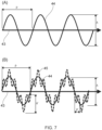
- the second sub-pattern 44 may be periodic, in that it comprises a pattern that repeats about and along a centre-line defined by the first sub-pattern 43.
- the second-sub-pattern 44 may be defined by a spatially-distributed arrangement of localised weaknesses 42 throughout the plies of the fan blade 31.
- the periodicity, P, and amplitude, A of the periodic pattern may vary along the length of the first sub-pattern 41.
- Periodicity P may be in the range of 0.1 millimetres to 5 millimetres.
- Amplitude A may be in the range of 0.1 millimetres to 5 millimetres.
- a crack will initiate and propagate within the blade, such that the crack propagates from the crack initiation site to the surface of the blade opposing the initiation site, and an outer portion of the blade is released.
- Changing the periodicity P and/or amplitude A of the periodic pattern along the first sub-pattern 41 changes the localised toughness of the blade because these changes also change the separation distance between adjacent localised weaknesses.
- the separation between adjacent localised weaknesses is increased, thus increasing the energy required to initiate or propagate a crack.
- the separation between adjacent localised weaknesses may be separated by at least one ply layer which does not comprise a localised weakness. This promotes additional delamination at the interface between the ply layers, increasing energy absorption and increasing localised toughness.
- the separation between adjacent localised weaknesses is reduced, thus decreasing the energy required to initiate or propagate a crack.
- the separation between adjacent localised weaknesses is increased, thus increasing the energy required to initiate or propagate a crack, whilst if the amplitude A of the second sub pattern is decreased, the separation between adjacent localised weaknesses is reduced, thus decreasing the energy required to initiate or propagate a crack.
- Changing the amplitude A and or periodicity P of the crack therefore provides a means to control the energy absorbed during crack propagation whilst ensuring that the crack propagates in the desired, pre-defined direction.
- a smaller amplitude A and/or periodicity P pattern within the laminate may be initially used to ensure a crack propagates in a desired direction. Following establishment (initiation) of the crack, a larger amplitude A and/or periodicity P may then be used to increase energy absorption. If the crack then propagates within a portion of the laminate such that the local geometry increases the propensity of the crack to propagate in an unintended direction, then the amplitude A, and or periodicity P may be reduced to reduce this risk.
- the amplitude A and /or periodicity P may be varied along the pre-defined pattern 41b to satisfy the competing goals of controlling the direction of crack propagation and increasing energy absorption during crack propagation.
- a of the second sub-pattern 44 along the crack propagation path defined by the first sub-pattern 43 may also be desirable from an operational viewpoint of the fan 13 of the gas turbine engine 10.
- the periodicity, P and/or amplitude, A of the second sub-pattern 44 may therefore be varied along the trajectory of crack propagation such that a crack may propagate more easily (requiring less energy) through the inner ply layers of the fan blade 31 than in the outer ply layers.
- at least one of the periodicity P and amplitude A of the second-sub-pattern within the propagation zone may be smaller than in the initiation zone.
- a potential advantage of this approach is that, by suitable selection of P and A throughout the blade, a simple visual inspection of the fan blade may be provided - i.e., although localised damage may be visible on the surface of the blade, the fact that the blade is otherwise intact (no portion of the blade has been lost) shows that the affected fan blade is suitable for at least short term operation, such that the aircraft may be scheduled to be inspected at an overhaul base, minimising operational disruption for the operator of the aircraft to which the gas turbine engine 10 is attached.
- This may be particularly advantageous for a passenger carrying aircraft, as these aircraft are operated with a high degree of utilisation, making unplanned and unscheduled maintenance highly-disruptive to the operation of the aircraft.
- the pre-defined pattern 41 additionally comprises a third sub-pattern 45.
- the third sub-pattern 45 may be superposed on the second sub-pattern 44 and the first sub-pattern 43. An example of this is illustrated in FIG. 7B .
- the third sub-pattern 45 may have a periodicity P' and an amplitude A'.
- the periodicity, P', and amplitude, A' of the third sub-pattern may vary along the length of the first sub-pattern 43 and/or second sub-pattern 44.
- a length-scale of the third sub-pattern 45 is smaller than a length scale of the second sub-pattern 44, i.e., P' is smaller than P and/or A' is smaller than A.
- the third sub-pattern 45 may be discontinuous. That is, the third sub-pattern may only be present along a length of a portion of pre-defined pattern 41.
- Incorporating a third sub-pattern 45 may be advantageous because it increases the total surface area of the crack to be formed, increasing the energy absorbed and/or providing further means to adjust the toughness of the laminate 39.
- a method 800 for controlling the failure of a composite article i.e., a fan blade
- a composite article i.e., a fan blade
- FIG. 8 A method 800 for controlling the failure of a composite article (i.e., a fan blade), as a form of kinetic energy absorptive composite article, is also now disclosed in FIG. 8 .
- a desired crack propagation surface Prior to performing the method, a desired crack propagation surface is first determined.
- the desired crack propagation surface may separate the kinetic energy absorptive component into at least two parts.
- the desired crack propagation surface may separate a fan blade 31 into a radially outer portion 31a and a radially inner portion 31b.
- the desired crack propagation surface may be determined by consideration of the mass of the radially outer portion 31a, and as a consequence, the impact energy of the radially outer portion 31a on a fan containment system and/or a following blade 31, rotating about axis 11 as a component of fan 13.
- the determination of the desired crack propagation surface may be conducted as part of a design optimisation exercise for the gas turbine engine 10.
- Impact analysis for example, using finite element techniques, may be performed to determine the desired crack propagation surface.
- an impact analysis of the response of the fan blade to an impact by a foreign body, such as a bird is performed.
- the impact analysis may determine a response of the blade to the impact, i.e., the impact analysis may determine a modal shape of the blade.
- the impact analysis may consider a range of different impact energies (i.e., different masses of foreign body), impacting at different locations (variations in blade chord and/or radius).
- a pattern 41b of localised weaknesses 42 that are configured to cause fracture along this surface are determined.
- the pattern 41b of localised weaknesses 42 comprise the first sub-pattern 43 and second sub-pattern 44, as previously disclosed.
- the pattern 41 may optionally comprise the third sub-pattern 45 and/or further sub-patterns of progressively smaller length scale superposed on the first sub-pattern 43 and second sub-pattern 44.
- the pattern 41b of localised weaknesses is spatially distributed within the ply layers of the laminate 39 that forms the kinetic energy absorptive composite article 31.
- a ply-specific pattern (a ply pre-defined pattern) 41a is then determined for each ply 50 that comprises at least one localised weakness 42.
- the required ply, location, orientation and /or size of each of the localised weaknesses 42in the composite article is then recorded.
- the record may be made, for example in a ply-book or an addendum to a ply-book.
- the method 800 may be performed.
- the plies may be of any suitable type.
- the plies may be "pre-preg" plies, comprising at least one layer of pre-impregnated fiber within a partially cured polymer matrix.
- Each ply is laid individually, with successive plies added sequentially to form the finished laminate.
- the at least one localised weakness is made to the ply before the subsequent ply is overlaid. Determination of whether at least one localised weakness is to be introduced to a ply may be made in dependence upon consulting a record, for example, in dependence upon a ply-book.
- At step 802 at least one localised weakness may be introduced to the ply that has been laid down.
- the at least one localised weakness may be introduced to form a portion of the pre-defined pattern 41. It will be appreciated from the preceding disclosure that according to which ply is laid down, no localised weakness 42 may be introduced to a specific ply layer, or at least one localised weakness 42 may be introduced.
- the at least one localised weakness may be introduced (created) within the ply layer by a variety of means.
- introducing the localised weakness may comprise severing or partially severing a single fiber or grouping of adjacent fibers of a ply.
- introducing the localised weakness may comprise severing fibers of adjacent layers simultaneously.
- the localised weaknesses within the laminate may therefore be of different sizes.
- the length of the localised weaknesses may be in the range of 10 to 50 microns.
- Severing may be performed by a cutting process, such as mechanical cutting with a blade or machine tool, or laser cutting.
- the localised weakness may be formed by a spray process, in which a chemical is locally applied to the ply.
- the chemical applied may be PTFE.
- the severing means may be comprised within a ply-layup tool.
- lay-up of the sequential ply layers may comprise application of a roller, to provide pressure on the ply being laid, such that the pre-preg ply adheres to the pre-preg layer beneath it, and that air-bubbles that would otherwise be trapped between the layers, are removed.
- the roller may be comprised within a ply-layup tool, mounted to the head of a robotic arm.
- translation and rotation of the head of the robotic arm may be controlled in up to 6 degrees of freedom (three-dimensional translation of the head, rotation of the head about up to three orthogonal axes of rotation).
- the location and orientation of the ply-layup tool mounted to the head of the robotic arm may be controlled.
- the severing means within the ply-layup tool, the location and orientation of the severing means are therefore also known.
- the localised weaknesses in each ply layer than comprises at least one weakness, may therefore be accurately made.
- a three-dimensional pre-defined pattern 41b of localised weaknesses 42 may be formed throughout the laminate 39 of the fan blade 31.
- This three-dimensional pattern extends through at least a portion of the fan blade 31.
- a kinetic energy absorptive composite article such as a fan blade may comprise a plurality of different pre-defined patterns 41a 41b, each of which is configured to direct a different crack in a different direction.
- the fan blade may be separated into a plurality (multitude) of smaller portions.
- the fan blade 31 may thus be described as frangible.
- method steps 801 and 802 may be reversed. That is, localised weaknesses may be introduced to a ply, prior to the ply being laid up on an adjacent ply during the manufacture of the kinetic energy absorptive composite article.
Landscapes
- Engineering & Computer Science (AREA)
- General Engineering & Computer Science (AREA)
- Mechanical Engineering (AREA)
- Chemical & Material Sciences (AREA)
- Materials Engineering (AREA)
- Composite Materials (AREA)
- Architecture (AREA)
- Structures Of Non-Positive Displacement Pumps (AREA)
Applications Claiming Priority (1)
| Application Number | Priority Date | Filing Date | Title |
|---|---|---|---|
| GBGB2307925.4A GB202307925D0 (en) | 2023-05-26 | 2023-05-26 | Kinetic energy absorptive composite article |
Publications (1)
| Publication Number | Publication Date |
|---|---|
| EP4467775A1 true EP4467775A1 (de) | 2024-11-27 |
Family
ID=87060962
Family Applications (1)
| Application Number | Title | Priority Date | Filing Date |
|---|---|---|---|
| EP24173264.3A Pending EP4467775A1 (de) | 2023-05-26 | 2024-04-30 | Kinetische energie absorbierender verbundartikel |
Country Status (3)
| Country | Link |
|---|---|
| US (1) | US12429104B2 (de) |
| EP (1) | EP4467775A1 (de) |
| GB (1) | GB202307925D0 (de) |
Families Citing this family (1)
| Publication number | Priority date | Publication date | Assignee | Title |
|---|---|---|---|---|
| US12509989B2 (en) | 2024-05-03 | 2025-12-30 | Rtx Corporation | Mitigating impact of blade out event |
Citations (5)
| Publication number | Priority date | Publication date | Assignee | Title |
|---|---|---|---|---|
| US8647072B2 (en) * | 2010-03-04 | 2014-02-11 | Rolls-Royce Plc | Component comprising a resin matrix |
| US20170370376A1 (en) * | 2015-01-13 | 2017-12-28 | General Electric Company | A composite airfoil with fuse architecture |
| US20200116027A1 (en) * | 2018-10-16 | 2020-04-16 | General Electric Company | Frangible Gas Turbine Engine Airfoil with Chord Reduction |
| EP3705282A1 (de) * | 2018-02-26 | 2020-09-09 | The Boeing Company | Verfahren zur absorption der kinetischen energie und absorbierender verbundartikel |
| US20230003132A1 (en) * | 2021-07-02 | 2023-01-05 | General Electric Company | Frangible airfoil |
Family Cites Families (8)
| Publication number | Priority date | Publication date | Assignee | Title |
|---|---|---|---|---|
| DE3722255A1 (de) * | 1987-07-06 | 1989-01-19 | Uniroyal Englebert Gmbh | Behaelter |
| US6048426A (en) * | 1996-11-15 | 2000-04-11 | Brigham Young University | Method of making damped composite structures with fiber wave patterns |
| US8720825B2 (en) * | 2005-03-31 | 2014-05-13 | The Boeing Company | Composite stiffeners for aerospace vehicles |
| US8618004B2 (en) * | 2006-03-16 | 2013-12-31 | Masanori Kubota | Multifunctional composites |
| GB2485758B (en) | 2010-09-22 | 2013-03-13 | Gkn Aerospace Services Ltd | Net edge method |
| US10227170B2 (en) * | 2015-11-23 | 2019-03-12 | The Boeing Company | Impact resistant liquid bladders |
| US10450870B2 (en) * | 2016-02-09 | 2019-10-22 | General Electric Company | Frangible gas turbine engine airfoil |
| US10493720B2 (en) * | 2018-02-26 | 2019-12-03 | The Boeing Company | Kinetic energy absorptive composite article and absorption method |
-
2023
- 2023-05-26 GB GBGB2307925.4A patent/GB202307925D0/en not_active Ceased
-
2024
- 2024-04-30 EP EP24173264.3A patent/EP4467775A1/de active Pending
- 2024-05-22 US US18/670,836 patent/US12429104B2/en active Active
Patent Citations (5)
| Publication number | Priority date | Publication date | Assignee | Title |
|---|---|---|---|---|
| US8647072B2 (en) * | 2010-03-04 | 2014-02-11 | Rolls-Royce Plc | Component comprising a resin matrix |
| US20170370376A1 (en) * | 2015-01-13 | 2017-12-28 | General Electric Company | A composite airfoil with fuse architecture |
| EP3705282A1 (de) * | 2018-02-26 | 2020-09-09 | The Boeing Company | Verfahren zur absorption der kinetischen energie und absorbierender verbundartikel |
| US20200116027A1 (en) * | 2018-10-16 | 2020-04-16 | General Electric Company | Frangible Gas Turbine Engine Airfoil with Chord Reduction |
| US20230003132A1 (en) * | 2021-07-02 | 2023-01-05 | General Electric Company | Frangible airfoil |
Non-Patent Citations (1)
| Title |
|---|
| MENCATTELLI LORENZO ET AL: "Bio-inspired design for enhanced damage tolerance of self-reinforced polypropylene/carbon fibre polypropylene hybrid composites", COMPOSITES PART A, vol. 121, 25 March 2019 (2019-03-25) - 25 March 2019 (2019-03-25), pages 341 - 352, XP085670854, ISSN: 1359-835X, DOI: 10.1016/J.COMPOSITESA.2019.03.028 * |
Also Published As
| Publication number | Publication date |
|---|---|
| US12429104B2 (en) | 2025-09-30 |
| US20240392855A1 (en) | 2024-11-28 |
| GB202307925D0 (en) | 2023-07-12 |
Similar Documents
| Publication | Publication Date | Title |
|---|---|---|
| EP2363271B1 (de) | Mehrlagiges Komponent mit Trennmaterial zwischen den Lagen | |
| Marsh | Aero engines lose weight thanks to composites | |
| US5785498A (en) | Composite fan blade trailing edge reinforcement | |
| US5375978A (en) | Foreign object damage resistant composite blade and manufacture | |
| Roberts et al. | Impact testing and analysis of composites for aircraft engine fan cases | |
| McCarthy et al. | Polymer composite applications to aerospace equipment | |
| EP2096269A2 (de) | Anordnung von Gebläseschienenverkleidungen für ein Gasturbinentriebwerk | |
| Zhou et al. | Bird-striking damage of rotating laminates using SPH-CDM method | |
| EP4467775A1 (de) | Kinetische energie absorbierender verbundartikel | |
| EP2071137A2 (de) | Verfahren zur Reparatur eines Berstschutzrings aus Verbundwerkstoff | |
| Marsh | Composites get in deep with new-generation engine | |
| Ahmad et al. | Progressive failure analysis of helicopter rotor blade under aeroelastic loading | |
| Soutis | Recent advances in building with composites | |
| Ashwill et al. | Composite Materials For Innovative Wind Turbine Blades. | |
| CA3260537A1 (en) | Reinforced fiber resistant to significant impacts for leading edge protection of aerodynamic structures | |
| Wiggenraad et al. | Design optimization of stiffened composite panels with buckling and damage tolerance constraints | |
| US20110217517A1 (en) | Process for manufacturing a layered composite component | |
| Reddick Jr | Safe-life and damage-tolerant design approaches for helicopter structures | |
| EP4198263B1 (de) | Rotierende verbundwerkstoff-schaufelkomponente mit z-stiften | |
| Kazemi et al. | Novel concepts for automated fibre placement ply-drops with higher strength | |
| Poe | Residual strength of composite aircraft structures with damage | |
| Kaushik et al. | Impact Analysis of Uncontained Engine | |
| CN116539312B (zh) | 用于包容试验的叶片分离装置 | |
| Roberts et al. | Impact testing of composites for aircraft engine fan cases | |
| US12415333B2 (en) | Containment structure |
Legal Events
| Date | Code | Title | Description |
|---|---|---|---|
| PUAI | Public reference made under article 153(3) epc to a published international application that has entered the european phase |
Free format text: ORIGINAL CODE: 0009012 |
|
| STAA | Information on the status of an ep patent application or granted ep patent |
Free format text: STATUS: THE APPLICATION HAS BEEN PUBLISHED |
|
| AK | Designated contracting states |
Kind code of ref document: A1 Designated state(s): AL AT BE BG CH CY CZ DE DK EE ES FI FR GB GR HR HU IE IS IT LI LT LU LV MC ME MK MT NL NO PL PT RO RS SE SI SK SM TR |
|
| STAA | Information on the status of an ep patent application or granted ep patent |
Free format text: STATUS: REQUEST FOR EXAMINATION WAS MADE |
|
| 17P | Request for examination filed |
Effective date: 20250403 |