EP4467711A1 - Condensation channel for drying apparatus, and drying apparatus - Google Patents
Condensation channel for drying apparatus, and drying apparatus Download PDFInfo
- Publication number
- EP4467711A1 EP4467711A1 EP22920090.2A EP22920090A EP4467711A1 EP 4467711 A1 EP4467711 A1 EP 4467711A1 EP 22920090 A EP22920090 A EP 22920090A EP 4467711 A1 EP4467711 A1 EP 4467711A1
- Authority
- EP
- European Patent Office
- Prior art keywords
- arc
- side wall
- airflow
- shaped
- condensation channel
- Prior art date
- Legal status (The legal status is an assumption and is not a legal conclusion. Google has not performed a legal analysis and makes no representation as to the accuracy of the status listed.)
- Pending
Links
Images




Classifications
-
- D—TEXTILES; PAPER
- D06—TREATMENT OF TEXTILES OR THE LIKE; LAUNDERING; FLEXIBLE MATERIALS NOT OTHERWISE PROVIDED FOR
- D06F—LAUNDERING, DRYING, IRONING, PRESSING OR FOLDING TEXTILE ARTICLES
- D06F58/00—Domestic laundry dryers
- D06F58/20—General details of domestic laundry dryers
- D06F58/24—Condensing arrangements
-
- D—TEXTILES; PAPER
- D06—TREATMENT OF TEXTILES OR THE LIKE; LAUNDERING; FLEXIBLE MATERIALS NOT OTHERWISE PROVIDED FOR
- D06F—LAUNDERING, DRYING, IRONING, PRESSING OR FOLDING TEXTILE ARTICLES
- D06F58/00—Domestic laundry dryers
- D06F58/20—General details of domestic laundry dryers
- D06F58/22—Lint collecting arrangements
Definitions
- the present disclosure relates to the technical field of household appliances, and specifically provides a condensation channel for a drying apparatus, and a drying apparatus.
- a drying apparatus refers to a machine that can use hot air to dry clothing.
- the drying apparatus mainly includes a washing-drying integrated machine, a clothing dryer, or a drying machine, etc.
- washing-drying integrated machine As an example, it is an intelligent apparatus in which rinsing, spinning, and drying functions are integrated together. Due to its special advantages such as high cost-effectiveness, strong spatial inclusiveness, and washing-drying integrated operations that are time-saving and laborsaving, the washing-drying integrated machine is currently widely welcomed by users in the household appliance market.
- a filter screen is mostly arranged in the midway of circulating air path to block the clothing lint generated by drying.
- the blocking effect of the filter screen on the lint is poor.
- the present disclosure aims to solve the above technical problem, that is, to solve the problem that the air duct and fan of existing drying apparatuses can be easily blocked by lint.
- a flushing nozzle is provided on the condensation channel, and a spray port of the flushing nozzle faces an inner side wall of the condensation channel.
- the water blocking structure is a water blocking protrusion formed on the front side wall.
- a first arc-shaped guide structure and a second arc-shaped guide structure are also provided on the rear side wall, so that the first airflow and the second airflow can flow smoothly toward the first arc-shaped structure and the second arc-shaped structure respectively.
- the flow split structure is symmetrically arranged left and right, and a centerline of the flow split structure coincides with a centerline of the air inlet so that the first airflow and the second airflow have substantially the same volume.
- the flow split structure includes a first arc-shaped flow split section and a second arc-shaped flow split section; one end of the first arc-shaped flow split section is smoothly connected to the first arc-shaped structure, the other end of the first arc-shaped flow split section is smoothly connected to one end of the second arc-shaped flow split section, and the other end of the second arc-shaped flow split section is smoothly connected to the second arc-shaped structure.
- a main water guide groove and branch water guide grooves are provided on the front side walls; the number of branch water guide grooves is two, top ends of the two branch water guide grooves are both communicated with a bottom end of the main water guide groove, and bottom ends of the two branch water guide grooves are respectively connected to two said water blocking structures located inside the double spiral channels.
- the condensation channel of the present disclosure includes two double spiral channels that are arranged side by side and are independent from each other; by arranging a water blocking structure on the side wall of the double spiral channel, the cooling water flow is dispersed into water splashes, which can not only flush the side wall of the double spiral channel at the same time the drying program is executed, but also can dissolve the lint in the circulating airflow.
- a first arc-shaped structure, a second arc-shaped structure, and a flow split structure are arranged on the front side wall; the left side wall and the right side wall of the double spiral channel are both arc-shaped, and the gas entering from the air inlet is divided by the flow split structure into a first airflow and a second airflow, which can rotate and rise.
- the travel of the first airflow and the second airflow in the condensation channel is extended, thereby improving the cooling effect.
- the dispersed cooling water splashes are carried by the two streams of rotating and rising airflows, forming "whirlwind” like water splashes in the condensation channel.
- a flushing nozzle is arranged on the condensation channel, and a spray port of the flushing nozzle faces an inner side wall of the condensation channel.
- the number of the spray port is multiple, and the multiple spray ports spray in different directions. Through such an arrangement, the flushing effect on the inner wall of the condensation channel can be improved.
- the water blocking structure is also arranged on the front side wall of the double spiral channel and has a triangular shape, and a centerline of the water blocking structure coincides with a centerline of the flow split structure so that the cooling water is evenly dispersed.
- the flow split structure is symmetrically arranged left and right, and the centerline of the flow split structure coincides with the centerline of the air inlet.
- the first airflow and the second airflow can have substantially the same volume. In this way, after the first airflow and the second airflow meet at a position near the rear side wall, they will not disperse each other, but can flow in parallel toward the front side wall under the interaction, and then respectively enter the first arc-shaped structure and the second arc-shaped structure arranged on the front side wall.
- a first arc-shaped guide structure and a second arc-shaped guide structure are arranged on the rear side wall so that the first airflow and the second airflow can flow smoothly toward the first arc-shaped structure and the second arc-shaped structure respectively.
- the first airflow and the second airflow meet, the movement trend of the first airflow and the movement trend of the second airflow are both facing the front side wall. Therefore, after the first airflow and the second airflow meet, they can interact with each other, so that the first airflow moves toward the first arc-shaped structure and the second airflow moves toward the second arc-shaped structure.
- the drying apparatus further provided by the present disclosure on the basis of the above technical solutions, due to having the above condensation channel adopted, can have the technical effect of the above condensation channel.
- the drying apparatus of the present disclosure can better filter the lint and has higher drying efficiency.
- 1 body; 10: water blocking structure; 11: first arc-shaped structure; 12: second arc-shaped structure; 13: flow split structure; 14: left side wall; 15: right side wall; 16: rear side wall; 131: first arc-shaped flow split section; 132: second arc-shaped flow split section; 161: first arc-shaped guide structure; 162: second arc-shaped guide structure; 171: main water guide groove; 172: branch water guide groove; 18: air outlet; 19: air inlet; 2: cooling water pipe; 3: flushing nozzle; 31: spray port; 4: inner cylinder; 5: outer cylinder; 6: fan; 7: air pipe; 8: corrugated pipe.
- connection may be a fixed connection, or a detachable connection, or an integral connection; it may be a direct connection, or an indirect connection implemented through an intermediate medium, or internal communication between two elements.
- connection may be a fixed connection, or a detachable connection, or an integral connection; it may be a direct connection, or an indirect connection implemented through an intermediate medium, or internal communication between two elements.
- the washing-drying integrated machine of the present disclosure includes a cabinet, in which an inner cylinder, an outer cylinder, a condensation channel, a fan, a heater, and an air pipe are provided.
- the heater is installed in the air pipe, one end of the air pipe is communicated with the outer cylinder, the other end of the air pipe is communicated with an air outlet of the fan, and the fan is installed between the condensation channel and the air pipe.
- air can circulate between the outer cylinder, the condensation channel, and the heater.
- dry air is heated to become dry hot air, which then enters the outer cylinder and the inner cylinder along the air pipe, exchanges heat with wet clothing in the inner cylinder, and takes away the moisture in the clothing to form relatively humid hot air, which then enters the condensation channel.
- the condensation effect of the condensation channel the moisture in the relatively humid hot air is condensed into water, and the condensed air becomes relatively dry cold air, which then enters the air pipe and is heated by the heater to become dry hot air before entering the next cycle. This cycle repeats again and again until the drying program is completed.
- an independent condenser can be provided, and the condensation channel can be formed inside the condenser.
- the condenser can be installed on a rear wall of the outer cylinder, or a shell and the rear wall of the outer cylinder together can enclose the condensation channel, etc.
- the adjustment and change to the specific formation of the condensation channel do not deviate from the principle and scope of the present disclosure, and should all be defined within the scope of protection of the present disclosure.
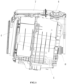
- FIG. 1 is a first schematic view of the structure of the washing-drying integrated machine of the present disclosure
- FIG. 2 is a second schematic view of the structure of the washing-drying integrated machine of the present disclosure.
- the washing-drying integrated machine of the present disclosure includes a cabinet, in which an inner cylinder 4, an outer cylinder 5, a condenser, a fan 6, a heater (not shown in the figure) and an air pipe 7 are provided.
- the heater is installed in the air pipe 7, one end of the air pipe 7 is communicated with the outer cylinder 5, the other end of the air pipe 7 is communicated with an air outlet of the fan 6, and the fan 6 is installed between the condenser and the air pipe 7.
- a condensation channel is formed inside the condenser.
- the condenser of the present disclosure includes a body 1 and a cooling water pipe 2.
- An upper part of the body 1 is provided with an air outlet 18, which is communicated with an air inlet of the fan 6.
- a lower part of the body 1 is provided with an air inlet 19, which is communicated with the outer cylinder 5 through a corrugated pipe 8.
- a condensation channel is formed inside the body 1. The top of the condensation channel is communicated with the air outlet 18, the bottom of the condensation channel is communicated with the air inlet 19, and the cooling water pipe 2 is communicated with the condensation channel.
- the condensation channel includes two double spiral channels that are arranged side by side and are independent from each other.
- the two double spiral channels are arranged left and right side by side, and the two double spiral channels are independent from each other.
- the number of air inlet 19 is two, and the two air inlets 19 are communicated with the two double spiral channels respectively. After entering the two double spiral channels from the air inlets 19, gas rotates and rises along the double spiral channels without mutual interference, and is finally discharged from the air outlet 18.
- the body 1 of the condenser is provided with only one air outlet 18, and top ends of the two double spiral channels are both communicated with this air outlet 18.
- a water blocking structure 10 is provided on the inner side wall of the double spiral channel.
- the cooling water flowing into the double spiral channel reaches the water blocking structure 10, it is dispersed into water splashes.
- the water splashes can not only flush the inner side wall of the double spiral channel at the same time the drying program is executed, but also can dissolve the lint in the circulating airflow. Then, the lint flows out with the condensate water from the air inlet 19 and is finally discharged out of the machine through a drainage pipe.
- the condenser can also filter the lint, reduce the continuous circulation of lint in the drying system, "purify" the airflow that carries the lint, reduce the phenomenon of the lint adhering to various elements and components of the drying module, and alleviate the situation of blocking the drying air duct by the lint.
- the water blocking structure 10 can be arranged as a water blocking rib, a water blocking block, a water blocking plate, etc. Such adjustment and change to the specific structural form of the water blocking structure 10 do not deviate from the principle and scope of the present disclosure, and should all be defined within the scope of protection of the present disclosure.
- a front side wall of the double spiral channel is provided with a first arc-shaped structure 11, a second arc-shaped structure 12, and a flow split structure 13 located between the first arc-shaped structure 11 and the second arc-shaped structure 12; the flow split structure 13 is located below the water blocking structure 10; a left side wall 14 and a right side wall 15 of the double spiral channel are both configured into an arc shape, two ends of the left side wall 14 are smoothly connected to the first arc-shaped structure 11 and a left end of a rear side wall 16 respectively, and two ends of the right side wall 15 are smoothly connected to the second arc-shaped structure 12 and a right end of the rear side wall 16 respectively.
- the air inlet 19 is arranged on the rear side wall 16 of the double spiral channel, and the flow split structure 13 is opposite to the air inlet 19. Through such an arrangement, the gas entering from the air inlet 19 can right hit the flow split structure 13.
- the flow split structure 13 can divide the airflow into two streams of airflows (denoted as a first airflow and a second airflow) in such a way that the first airflow enters the first arc-shaped structure 11 substantially in a tangential direction of the first arc-shaped structure 11, and under the pushing effect of the subsequent airflow, the first airflow can rotate counterclockwise and rise along the first arc-shaped structure 11, the left side wall 14 and a left part of the rear side wall 16, as well as that the second airflow enters the second arc-shaped structure 12 substantially in a tangential direction of the second arc-shaped structure 12, and under the pushing effect of the subsequent airflow, the second airflow can rotate clockwise and rise along the second arc-shaped structure 12, the right side wall 15 and a right part of the rear side wall 16.
- the double spiral channel includes two gas channels.
- the first arc-shaped structure 11, the left side wall 14, and the left part of the rear side wall 16 form a first gas channel;
- the second arc-shaped structure 12, the right side wall 15, and the right part of the rear side wall 16 form a second gas channel.
- the gas After entering the double spiral channel from the air inlet 19, the gas is divided into the first airflow and the second airflow by the flow split structure 13.
- the first airflow can rotate and rise along the inner wall of the first gas channel, and the second airflow can rotate and rise along the inner wall of the second gas channel.
- the flow split structure 13 is creatively arranged on the front side wall of the double spiral channel.
- the gas entering from the air inlet 19 is divided into the first airflow and the second airflow, so that the first airflow and the second airflow rotate and rise respectively.
- the travel of the first airflow and the second airflow in the condensation channel is extended, thereby improving the cooling effect.
- the dispersed cooling water splashes are carried by the two streams of rotating and rising airflows, forming "whirlwind” like water splashes in the condensation channel.
- vortex like water splashes with a certain liquid level height are formed in the condensation channel.
- the lint dissolves in the water splashes.
- the continuously fluctuating water splashes are used to flush the bottom of the condensation channel in real time, which can improve the filtering effect on the lint.
- the water blocking structure 10 is arranged near the top end of the flow split structure 13.
- the cooling water can meet two streams of spiral airflows immediately after being dispersed, which can have better lint filtration effect and condensation effect.
- the water blocking structure 10 can also be kept away from the air outlet 18, which can prevent water splashes from splashing from the air outlet 18 to the fan, and also prevent water splashes from being carried by the airflows into the inner cylinder 4 to reduce the drying efficiency.
- the flow split structure 13 includes a first arc-shaped flow split section 131 and a second arc-shaped flow split section 132; a left end of the first arc-shaped flow split section 131 is smoothly connected to the first arc-shaped structure 11, a right end of the first arc-shaped flow split section 131 is smoothly connected to a left end of the second arc-shaped flow split section 132, and a right end of the second arc-shaped flow split section 132 is smoothly connected to the second arc-shaped structure 12.
- the gas entering from the air inlet 19 hits the flow split structure 13 and is divided into the first airflow and the second airflow.
- the first airflow flows along the first arc-shaped flow split section 131 toward the first arc-shaped structure 11, and the second airflow flows along the second arc-shaped flow split section 132 toward the second arc-shaped structure 12.
- the flow split structure 13 is symmetrically arranged left and right, and a centerline of the flow split structure 13 coincides with a centerline of the air inlet 19.
- the first airflow and the second airflow can have substantially the same volume.
- they will not disperse each other, but can flow together in parallel toward the front side wall under the interaction, and then respectively enter the first arc-shaped structure 11 and the second arc-shaped structure 12 arranged on the front side wall.
- the first arc-shaped guide structure 161 and the second arc-shaped guide structure 162 are provided on the rear side wall 16 of the double spiral channel. Under the guidance of the first arc-shaped guide structure 161, the first airflow can smoothly flow toward the first arc-shaped structure 11. Similarly, under the guidance of the second arc-shaped guide structure 162, the second airflow can also smoothly flow toward the second arc-shaped structure 12.
- the first arc-shaped guide structure 161 and the second arc-shaped guide structure 162 it is possible to avoid direct collision from opposite directions between the first airflow and the second airflow.
- the movement trend of the first airflow and the movement trend of the second airflow are both facing the front side wall. Therefore, after the first airflow and the second airflow meet, they can interact with each other, so that the first airflow can smoothly move toward the first arc-shaped structure 11 and the second airflow can smoothly move toward the second arc-shaped structure 12.
- a middle partition can be provided in the double spiral channel.
- a front side of the middle partition is smoothly connected to the first arc-shaped structure 11 and the second arc-shaped structure 12, respectively.
- a rear side of the middle partition is smoothly connected to the left part and right part of the rear side wall 16, respectively.
- the rear side wall 16 of the double spiral channel is also configured into an arc shape.
- the rear side wall 16 includes two arc-shaped parts. Two ends of the left arc-shaped part are smoothly connected to the left side wall 14 and the first arc-shaped guide structure 161 respectively, and two ends of the right arc-shaped part are smoothly connected to the right side wall 15 and the second arc-shaped guide structure 162 respectively.
- a main water guide groove 171 and branch water guide grooves 172 are provided on the front side walls of the double spiral channels.
- the number of branch water guide grooves 172 is two, top ends of the two branch water guide grooves 172 are both communicated with a bottom end of the main water guide groove 171, and bottom ends of the two branch water guide grooves 172 are respectively connected to two water blocking structures 10 located inside the double spiral channels.
- cooling water is supplied into the double spiral channels through the cooling water pipe 2. After entering the main water guide groove 171, the cooling water flows downward along the main water guide groove 171, and then flows into the two branch water guide grooves 172 respectively, thus flowing into the two double spiral channels. When the cooling water flows to the water blocking structures 10, it is dispersed into water splashes.
- the water blocking structure 10 is also provided on the front side wall of the double spiral channel, and the water blocking structure 10 has a triangular shape.
- a top end of the water blocking structure 10 is aligned with the bottom end of the branch water guide groove 172, and the centerline of the water blocking structure 10 coincides with the centerline of the flow split structure 13, so that the cooling water is evenly dispersed.
- the water blocking structure 10 is preferably a water blocking protrusion formed on the front side wall.
- the condenser of the present disclosure further includes a flushing nozzle 3 which is arranged on the condensation channel, and a spray port 31 of the flushing nozzle 3 faces the inner side wall of the condensation channel.
- the flushing nozzle 3 sprays flushing water flow into the condenser to achieve the purpose of flushing and purifying.
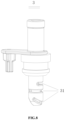
- the number of the spray port 31 is multiple, and the multiple spray ports 31 spray in different directions.
- the flushing effect on the inner wall of the condenser can be improved.
Landscapes
- Engineering & Computer Science (AREA)
- Textile Engineering (AREA)
- Detail Structures Of Washing Machines And Dryers (AREA)
- Separating Particles In Gases By Inertia (AREA)
- Drying Of Solid Materials (AREA)
Abstract
Description
- The present disclosure relates to the technical field of household appliances, and specifically provides a condensation channel for a drying apparatus, and a drying apparatus.
- A drying apparatus refers to a machine that can use hot air to dry clothing. The drying apparatus mainly includes a washing-drying integrated machine, a clothing dryer, or a drying machine, etc.
- Taking the washing-drying integrated machine as an example, it is an intelligent apparatus in which rinsing, spinning, and drying functions are integrated together. Due to its special advantages such as high cost-effectiveness, strong spatial inclusiveness, and washing-drying integrated operations that are time-saving and laborsaving, the washing-drying integrated machine is currently widely welcomed by users in the household appliance market.
- Currently, the self-cleaning problem of lint in the washing-drying integrated machine is still a major difficulty facing the industry. Due to the continuous mutual friction between clothing inside an inner cylinder, lint, fluffs and other impurities will be generated. These lint type impurities will continuously circulate in the system with airflow, and will adhere to various elements and components of the drying system and block them. If the lint is not cleaned in time, it may block an air duct and a fan, reduce the flow-through area, and cause a decrease in air volume, affecting a drying effect on the clothing.
- In the prior art, a filter screen is mostly arranged in the midway of circulating air path to block the clothing lint generated by drying. However, due to the limited structural area at the location where the filter screen is arranged, the blocking effect of the filter screen on the lint is poor.
- Accordingly, there is a need for a new technical solution in the art to solve the above problem.
- The present disclosure aims to solve the above technical problem, that is, to solve the problem that the air duct and fan of existing drying apparatuses can be easily blocked by lint.
- In a first aspect, the present disclosure provides a condensation channel for a drying apparatus, in which the condensation channel includes two double spiral channels that are arranged side by side and are independent from each other; a water blocking structure is provided on a side wall of each of the double spiral channels to disperse a cooling water flow flowing into the double spiral channel; a front side wall of the double spiral channel is further provided with a first arc-shaped structure, a second arc-shaped structure, and a flow split structure located between the first arc-shaped structure and the second arc-shaped structure; the flow split structure is located below the water blocking structure; an air inlet is formed on a rear side wall of the double spiral channel; a left side wall of the double spiral channel is configured into an arc shape, and two ends of the left side wall are smoothly connected to the first arc-shaped structure and the rear side wall respectively; a right side wall of the double spiral channel is configured into an arc shape, and two ends of the right side wall are smoothly connected to the second arc-shaped structure and the rear side wall respectively; the flow split structure is opposite to the air inlet, and the flow split structure is arranged to be capable of dividing the gas entering from the air inlet into a first airflow and a second airflow and enabling the first airflow and the second airflow to enter the first arc-shaped structure and the second arc-shaped structure respectively in a tangential direction of the first arc-shaped structure and a tangential direction of the second arc-shaped structure respectively, so that the first airflow can rotate and rise along the first arc-shaped structure, the left side wall, and a left part of the rear side wall, and that the second airflow can rotate and rise along the second arc-shaped structure, the right side wall, and a right part of the rear side wall.
- In a preferred technical solution of the condensation channel for the drying apparatus described above, a flushing nozzle is provided on the condensation channel, and a spray port of the flushing nozzle faces an inner side wall of the condensation channel.
- In a preferred technical solution of the condensation channel for the drying apparatus described above, the number of the spray port is multiple, and the multiple spray ports spray in different directions.
- In a preferred technical solution of the condensation channel for the drying apparatus described above, the water blocking structure is arranged on the front side wall and has a triangular shape, and a centerline of the water blocking structure coincides with a centerline of the flow split structure to evenly disperse the cooling water.
- In a preferred technical solution of the condensation channel for the drying apparatus described above, the water blocking structure is a water blocking protrusion formed on the front side wall.
- In a preferred technical solution of the condensation channel for the drying apparatus described above, a first arc-shaped guide structure and a second arc-shaped guide structure are also provided on the rear side wall, so that the first airflow and the second airflow can flow smoothly toward the first arc-shaped structure and the second arc-shaped structure respectively.
- In a preferred technical solution of the condensation channel for the drying apparatus described above, the flow split structure is symmetrically arranged left and right, and a centerline of the flow split structure coincides with a centerline of the air inlet so that the first airflow and the second airflow have substantially the same volume.
- In a preferred technical solution of the condensation channel for the drying apparatus described above, the flow split structure includes a first arc-shaped flow split section and a second arc-shaped flow split section; one end of the first arc-shaped flow split section is smoothly connected to the first arc-shaped structure, the other end of the first arc-shaped flow split section is smoothly connected to one end of the second arc-shaped flow split section, and the other end of the second arc-shaped flow split section is smoothly connected to the second arc-shaped structure.
- In a preferred technical solution of the condensation channel for the drying apparatus described above, a main water guide groove and branch water guide grooves are provided on the front side walls; the number of branch water guide grooves is two, top ends of the two branch water guide grooves are both communicated with a bottom end of the main water guide groove, and bottom ends of the two branch water guide grooves are respectively connected to two said water blocking structures located inside the double spiral channels.
- In a second aspect, the present disclosure also provides a drying apparatus, which includes the condensation channel described above.
- In a case where the above technical solutions are adopted, the condensation channel of the present disclosure includes two double spiral channels that are arranged side by side and are independent from each other; by arranging a water blocking structure on the side wall of the double spiral channel, the cooling water flow is dispersed into water splashes, which can not only flush the side wall of the double spiral channel at the same time the drying program is executed, but also can dissolve the lint in the circulating airflow. In addition, a first arc-shaped structure, a second arc-shaped structure, and a flow split structure are arranged on the front side wall; the left side wall and the right side wall of the double spiral channel are both arc-shaped, and the gas entering from the air inlet is divided by the flow split structure into a first airflow and a second airflow, which can rotate and rise. Through such an arrangement, the travel of the first airflow and the second airflow in the condensation channel is extended, thereby improving the cooling effect. Moreover, the dispersed cooling water splashes are carried by the two streams of rotating and rising airflows, forming "whirlwind" like water splashes in the condensation channel. By controlling the cooling water volume, vortex like water splashes with a certain liquid level height are formed in the condensation channel. When the airflows pass through this area, the lint dissolves in the water splashes. Meanwhile, at the air inlet where the lint is most likely to accumulate, the continuously fluctuating water splashes are used to flush the bottom of the condensation channel in real time, which can improve the filtering effect on the lint.
- Further, a flushing nozzle is arranged on the condensation channel, and a spray port of the flushing nozzle faces an inner side wall of the condensation channel. Through such an arrangement, after drying is completed, the flushing nozzle sprays flushing water flow into the condensation channel to achieve the purpose of flushing and purifying.
- Further, the number of the spray port is multiple, and the multiple spray ports spray in different directions. Through such an arrangement, the flushing effect on the inner wall of the condensation channel can be improved.
- Further, the water blocking structure is also arranged on the front side wall of the double spiral channel and has a triangular shape, and a centerline of the water blocking structure coincides with a centerline of the flow split structure so that the cooling water is evenly dispersed. Through such an arrangement, the two streams of spiral airflows can carry substantially equal amounts of cooling water splashes for rising, making dehumidification and filtration more uniform, and further improving the filtration effect on the lint and the condensation effect on the airflows.
- Further, the flow split structure is symmetrically arranged left and right, and the centerline of the flow split structure coincides with the centerline of the air inlet. Through such an arrangement, the first airflow and the second airflow can have substantially the same volume. In this way, after the first airflow and the second airflow meet at a position near the rear side wall, they will not disperse each other, but can flow in parallel toward the front side wall under the interaction, and then respectively enter the first arc-shaped structure and the second arc-shaped structure arranged on the front side wall.
- Further, a first arc-shaped guide structure and a second arc-shaped guide structure are arranged on the rear side wall so that the first airflow and the second airflow can flow smoothly toward the first arc-shaped structure and the second arc-shaped structure respectively. Through such an arrangement, under the guidance of the first arc-shaped guide structure and the second arc-shaped guide structure, it is possible to avoid direct collision from opposite directions between the first airflow and the second airflow. When the first airflow and the second airflow meet, the movement trend of the first airflow and the movement trend of the second airflow are both facing the front side wall. Therefore, after the first airflow and the second airflow meet, they can interact with each other, so that the first airflow moves toward the first arc-shaped structure and the second airflow moves toward the second arc-shaped structure.
- In addition, the drying apparatus further provided by the present disclosure on the basis of the above technical solutions, due to having the above condensation channel adopted, can have the technical effect of the above condensation channel. Compared with existing drying apparatuses, the drying apparatus of the present disclosure can better filter the lint and has higher drying efficiency.
- Preferred embodiments of the present disclosure will be described below in connection with the accompanying drawings, in which:
-
FIG. 1 is a first schematic view of the structure of the washing-drying integrated machine of the present disclosure; -
FIG. 2 is a second schematic view of the structure of the washing-drying integrated machine of the present disclosure; -
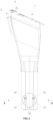
FIG. 3 is a first schematic view of the structure of the condenser of the present disclosure; -
FIG. 4 is a second schematic view of the structure of the condenser of the present disclosure; -
FIG. 5 is a sectional view taken along line A-A inFIG. 4 ; -
FIG. 6 is a third schematic view of the structure of the condenser of the present disclosure; -
FIG. 7 is a sectional view taken along line B-B inFIG. 6 ; and -
FIG. 8 is a schematic view of the structure of the flushing nozzle of the present disclosure. - 1: body; 10: water blocking structure; 11: first arc-shaped structure; 12: second arc-shaped structure; 13: flow split structure; 14: left side wall; 15: right side wall; 16: rear side wall; 131: first arc-shaped flow split section; 132: second arc-shaped flow split section; 161: first arc-shaped guide structure; 162: second arc-shaped guide structure; 171: main water guide groove; 172: branch water guide groove; 18: air outlet; 19: air inlet; 2: cooling water pipe; 3: flushing nozzle; 31: spray port; 4: inner cylinder; 5: outer cylinder; 6: fan; 7: air pipe; 8: corrugated pipe.
- Preferred embodiments of the present disclosure will be described below with reference to the accompanying drawings. It should be understood by those skilled in the art that these following embodiments are only used to explain the technical principle of the present disclosure, and are not intended to limit the scope of protection of the present disclosure.
- For example, although the following embodiments are described below in connection with a washing-drying integrated machine, the present disclosure is still applicable to other drying apparatuses, such as a clothing dryer, a drying machine, etc. Such adjustments and changes to the application object do not deviate from the principle and scope of the present disclosure, and should all be defined within the scope of protection of the present disclosure.
- It should be noted that in the description of the present disclosure, terms indicating directional or positional relationships, such as "upper", "lower", "left", "right", "front", "rear", "top", "bottom", "inner", "outer" and the like, are based on the directional or positional relationships shown in the accompanying drawings. They are only used for ease of description, and do not indicate or imply that the device or element must have a specific orientation, or must be constructed or operated in a specific orientation; therefore, they should not be considered as limitations to the present disclosure. In addition, terms "first" and "second" are only used for descriptive purpose, and should not be understood as indicating or implying relative importance.
- In addition, it should also be noted that in the description of the present disclosure, unless otherwise clearly specified and defined, terms "arrange", "communicate" and "connect" should be understood in a broad sense; for example, the connection may be a fixed connection, or a detachable connection, or an integral connection; it may be a direct connection, or an indirect connection implemented through an intermediate medium, or internal communication between two elements. For those skilled in the art, the specific meaning of the above terms in the present disclosure can be interpreted according to specific situations.
- Specifically, the washing-drying integrated machine of the present disclosure includes a cabinet, in which an inner cylinder, an outer cylinder, a condensation channel, a fan, a heater, and an air pipe are provided. The heater is installed in the air pipe, one end of the air pipe is communicated with the outer cylinder, the other end of the air pipe is communicated with an air outlet of the fan, and the fan is installed between the condensation channel and the air pipe.
- In the process of executing a drying program by the washing-drying integrated machine, under the action of the fan, air can circulate between the outer cylinder, the condensation channel, and the heater. Under the action of the heater, dry air is heated to become dry hot air, which then enters the outer cylinder and the inner cylinder along the air pipe, exchanges heat with wet clothing in the inner cylinder, and takes away the moisture in the clothing to form relatively humid hot air, which then enters the condensation channel. Through the condensation effect of the condensation channel, the moisture in the relatively humid hot air is condensed into water, and the condensed air becomes relatively dry cold air, which then enters the air pipe and is heated by the heater to become dry hot air before entering the next cycle. This cycle repeats again and again until the drying program is completed.
- It should be noted that in practical applications, an independent condenser can be provided, and the condensation channel can be formed inside the condenser. The condenser can be installed on a rear wall of the outer cylinder, or a shell and the rear wall of the outer cylinder together can enclose the condensation channel, etc. The adjustment and change to the specific formation of the condensation channel do not deviate from the principle and scope of the present disclosure, and should all be defined within the scope of protection of the present disclosure.
- In the following, the technical solutions of the present disclosure will be described using an example in which an independent condenser is provided and the condensation channel is formed inside the condenser.
- Firstly, reference is made to
FIGS. 1 and2 , in whichFIG. 1 is a first schematic view of the structure of the washing-drying integrated machine of the present disclosure, andFIG. 2 is a second schematic view of the structure of the washing-drying integrated machine of the present disclosure. - As shown in
FIGS. 1 and2 , the washing-drying integrated machine of the present disclosure includes a cabinet, in which aninner cylinder 4, anouter cylinder 5, a condenser, afan 6, a heater (not shown in the figure) and anair pipe 7 are provided. The heater is installed in theair pipe 7, one end of theair pipe 7 is communicated with theouter cylinder 5, the other end of theair pipe 7 is communicated with an air outlet of thefan 6, and thefan 6 is installed between the condenser and theair pipe 7. A condensation channel is formed inside the condenser. - With continued reference to
FIGS. 1 and2 and next with reference toFIGS. 3 to 5 , the condenser of the present disclosure includes abody 1 and a coolingwater pipe 2. An upper part of thebody 1 is provided with anair outlet 18, which is communicated with an air inlet of thefan 6. A lower part of thebody 1 is provided with anair inlet 19, which is communicated with theouter cylinder 5 through acorrugated pipe 8. A condensation channel is formed inside thebody 1. The top of the condensation channel is communicated with theair outlet 18, the bottom of the condensation channel is communicated with theair inlet 19, and the coolingwater pipe 2 is communicated with the condensation channel. - In the process of executing the drying program by the washing-drying integrated machine, cooling water can be provided to the condensation channel by the cooling
water pipe 2. The humid and hot air discharged from theinner cylinder 4 and theouter cylinder 5 enters the condensation channel through theair inlet 19 and exchanges heat with the cooling water in the condensation channel. The moisture in the humid and hot air is condensed into water, and the condensed air becomes relatively dry cold air, which is then discharged through theair outlet 18. The cooling water and condensate water are discharged from thelower air inlet 19. - With continued reference to
FIGS. 3 to 5 , the condensation channel includes two double spiral channels that are arranged side by side and are independent from each other. - Exemplarily, the two double spiral channels are arranged left and right side by side, and the two double spiral channels are independent from each other. The number of
air inlet 19 is two, and the twoair inlets 19 are communicated with the two double spiral channels respectively. After entering the two double spiral channels from theair inlets 19, gas rotates and rises along the double spiral channels without mutual interference, and is finally discharged from theair outlet 18. Thebody 1 of the condenser is provided with only oneair outlet 18, and top ends of the two double spiral channels are both communicated with thisair outlet 18. - It should be noted that in practical applications, an independent air outlet can also be set for each of the two double spiral channels. Such flexible adjustment and change do not deviate from the principle and scope of the present disclosure, and should all be defined within the scope of protection of the present disclosure.
- In addition, it should also be noted that the structures of the two double spiral channels are the same. The following description is given by taking the double spiral channel located on the left side as an example.
- As shown in
FIGS. 4 and5 , awater blocking structure 10 is provided on the inner side wall of the double spiral channel. When the cooling water flowing into the double spiral channel reaches thewater blocking structure 10, it is dispersed into water splashes. The water splashes can not only flush the inner side wall of the double spiral channel at the same time the drying program is executed, but also can dissolve the lint in the circulating airflow. Then, the lint flows out with the condensate water from theair inlet 19 and is finally discharged out of the machine through a drainage pipe. - Through such an arrangement, on the basis of achieving condensation, the condenser can also filter the lint, reduce the continuous circulation of lint in the drying system, "purify" the airflow that carries the lint, reduce the phenomenon of the lint adhering to various elements and components of the drying module, and alleviate the situation of blocking the drying air duct by the lint.
- It should be noted that in practical applications, the
water blocking structure 10 can be arranged as a water blocking rib, a water blocking block, a water blocking plate, etc. Such adjustment and change to the specific structural form of thewater blocking structure 10 do not deviate from the principle and scope of the present disclosure, and should all be defined within the scope of protection of the present disclosure. - With continued reference to
FIGS. 4 and5 , a front side wall of the double spiral channel is provided with a first arc-shapedstructure 11, a second arc-shapedstructure 12, and a flow splitstructure 13 located between the first arc-shapedstructure 11 and the second arc-shapedstructure 12; the flow splitstructure 13 is located below thewater blocking structure 10; aleft side wall 14 and aright side wall 15 of the double spiral channel are both configured into an arc shape, two ends of theleft side wall 14 are smoothly connected to the first arc-shapedstructure 11 and a left end of arear side wall 16 respectively, and two ends of theright side wall 15 are smoothly connected to the second arc-shapedstructure 12 and a right end of therear side wall 16 respectively. - With continued reference to
FIGS. 4 and5 , theair inlet 19 is arranged on therear side wall 16 of the double spiral channel, and the flow splitstructure 13 is opposite to theair inlet 19. Through such an arrangement, the gas entering from theair inlet 19 can right hit the flow splitstructure 13. The flow splitstructure 13 can divide the airflow into two streams of airflows (denoted as a first airflow and a second airflow) in such a way that the first airflow enters the first arc-shapedstructure 11 substantially in a tangential direction of the first arc-shapedstructure 11, and under the pushing effect of the subsequent airflow, the first airflow can rotate counterclockwise and rise along the first arc-shapedstructure 11, theleft side wall 14 and a left part of therear side wall 16, as well as that the second airflow enters the second arc-shapedstructure 12 substantially in a tangential direction of the second arc-shapedstructure 12, and under the pushing effect of the subsequent airflow, the second airflow can rotate clockwise and rise along the second arc-shapedstructure 12, theright side wall 15 and a right part of therear side wall 16. - It can be understood that the double spiral channel includes two gas channels. The first arc-shaped
structure 11, theleft side wall 14, and the left part of therear side wall 16 form a first gas channel; the second arc-shapedstructure 12, theright side wall 15, and the right part of therear side wall 16 form a second gas channel. After entering the double spiral channel from theair inlet 19, the gas is divided into the first airflow and the second airflow by the flow splitstructure 13. The first airflow can rotate and rise along the inner wall of the first gas channel, and the second airflow can rotate and rise along the inner wall of the second gas channel. - In the condenser of the present disclosure, the flow split
structure 13 is creatively arranged on the front side wall of the double spiral channel. Through the flow splitstructure 13, the gas entering from theair inlet 19 is divided into the first airflow and the second airflow, so that the first airflow and the second airflow rotate and rise respectively. By causing the first airflow and the second airflow to rotate and rise, the travel of the first airflow and the second airflow in the condensation channel is extended, thereby improving the cooling effect. - Moreover, the dispersed cooling water splashes are carried by the two streams of rotating and rising airflows, forming "whirlwind" like water splashes in the condensation channel. By controlling the cooling water volume, vortex like water splashes with a certain liquid level height are formed in the condensation channel. When the airflows pass through this area, the lint dissolves in the water splashes. Meanwhile, at the
air inlet 19 where the lint is most likely to accumulate, the continuously fluctuating water splashes are used to flush the bottom of the condensation channel in real time, which can improve the filtering effect on the lint. After the program runs stably, the volume of cooling water entering the condensation channel and the volume of cooling water exiting the condensation channel reach dynamic equilibrium. - Preferably, as shown in
FIGS. 6 and7 , thewater blocking structure 10 is arranged near the top end of the flow splitstructure 13. By arranging thewater blocking structure 10 near the top end of the flow splitstructure 13, the cooling water can meet two streams of spiral airflows immediately after being dispersed, which can have better lint filtration effect and condensation effect. - In addition, through such an arrangement, the
water blocking structure 10 can also be kept away from theair outlet 18, which can prevent water splashes from splashing from theair outlet 18 to the fan, and also prevent water splashes from being carried by the airflows into theinner cylinder 4 to reduce the drying efficiency. - Preferably, as shown in
FIGS. 4 and5 , the flow splitstructure 13 includes a first arc-shaped flow splitsection 131 and a second arc-shaped flow splitsection 132; a left end of the first arc-shaped flow splitsection 131 is smoothly connected to the first arc-shapedstructure 11, a right end of the first arc-shaped flow splitsection 131 is smoothly connected to a left end of the second arc-shaped flow splitsection 132, and a right end of the second arc-shaped flow splitsection 132 is smoothly connected to the second arc-shapedstructure 12. - The gas entering from the
air inlet 19 hits the flow splitstructure 13 and is divided into the first airflow and the second airflow. The first airflow flows along the first arc-shaped flow splitsection 131 toward the first arc-shapedstructure 11, and the second airflow flows along the second arc-shaped flow splitsection 132 toward the second arc-shapedstructure 12. - Preferably, as shown in
FIGS. 4 and5 , the flow splitstructure 13 is symmetrically arranged left and right, and a centerline of the flow splitstructure 13 coincides with a centerline of theair inlet 19. - Through such an arrangement, the first airflow and the second airflow can have substantially the same volume. In this way, after the first airflow and the second airflow meet at a position near the
rear side wall 16, they will not disperse each other, but can flow together in parallel toward the front side wall under the interaction, and then respectively enter the first arc-shapedstructure 11 and the second arc-shapedstructure 12 arranged on the front side wall. - Preferably, as shown in
FIGS. 4 and5 , the first arc-shapedguide structure 161 and the second arc-shapedguide structure 162 are provided on therear side wall 16 of the double spiral channel. Under the guidance of the first arc-shapedguide structure 161, the first airflow can smoothly flow toward the first arc-shapedstructure 11. Similarly, under the guidance of the second arc-shapedguide structure 162, the second airflow can also smoothly flow toward the second arc-shapedstructure 12. - Through such an arrangement, under the guidance of the first arc-shaped
guide structure 161 and the second arc-shapedguide structure 162, it is possible to avoid direct collision from opposite directions between the first airflow and the second airflow. When the first airflow and the second airflow meet, the movement trend of the first airflow and the movement trend of the second airflow are both facing the front side wall. Therefore, after the first airflow and the second airflow meet, they can interact with each other, so that the first airflow can smoothly move toward the first arc-shapedstructure 11 and the second airflow can smoothly move toward the second arc-shapedstructure 12. - It should be noted that in order to ensure that the first airflow and the second airflow can each rotate and rise independently, a middle partition can be provided in the double spiral channel. A front side of the middle partition is smoothly connected to the first arc-shaped
structure 11 and the second arc-shapedstructure 12, respectively. A rear side of the middle partition is smoothly connected to the left part and right part of therear side wall 16, respectively. By arranging the middle partition, the double spiral channel can be divided into two independent chambers. The first airflow can rotate and rise along an inner wall of a left chamber, and the second airflow can rotate and rise along an inner wall of a right chamber. - More preferably, the
rear side wall 16 of the double spiral channel is also configured into an arc shape. Exemplarily, as shown inFIG. 5 , therear side wall 16 includes two arc-shaped parts. Two ends of the left arc-shaped part are smoothly connected to theleft side wall 14 and the first arc-shapedguide structure 161 respectively, and two ends of the right arc-shaped part are smoothly connected to theright side wall 15 and the second arc-shapedguide structure 162 respectively. - Preferably, as shown in
FIGS. 6 and7 , a mainwater guide groove 171 and branchwater guide grooves 172 are provided on the front side walls of the double spiral channels. The number of branchwater guide grooves 172 is two, top ends of the two branchwater guide grooves 172 are both communicated with a bottom end of the mainwater guide groove 171, and bottom ends of the two branchwater guide grooves 172 are respectively connected to twowater blocking structures 10 located inside the double spiral channels. - In the process of executing the drying program by the washing-drying integrated machine, cooling water is supplied into the double spiral channels through the cooling
water pipe 2. After entering the mainwater guide groove 171, the cooling water flows downward along the mainwater guide groove 171, and then flows into the two branchwater guide grooves 172 respectively, thus flowing into the two double spiral channels. When the cooling water flows to thewater blocking structures 10, it is dispersed into water splashes. - Preferably, as shown in
FIGS. 6 and7 , thewater blocking structure 10 is also provided on the front side wall of the double spiral channel, and thewater blocking structure 10 has a triangular shape. A top end of thewater blocking structure 10 is aligned with the bottom end of the branchwater guide groove 172, and the centerline of thewater blocking structure 10 coincides with the centerline of the flow splitstructure 13, so that the cooling water is evenly dispersed. - Through such an arrangement, the two streams of spiral airflows can carry substantially equal amounts of cooling water splashes for rising, making dehumidification and filtration more uniform, and further improving the filtration effect on the lint and the condensation effect on the airflows. The
water blocking structure 10 is preferably a water blocking protrusion formed on the front side wall. - Preferably, as shown in
FIGS. 3 and4 , the condenser of the present disclosure further includes a flushing nozzle 3 which is arranged on the condensation channel, and aspray port 31 of the flushing nozzle 3 faces the inner side wall of the condensation channel. After drying is completed, the flushing nozzle 3 sprays flushing water flow into the condenser to achieve the purpose of flushing and purifying. - More preferably, as shown in
FIG. 8 , the number of thespray port 31 is multiple, and themultiple spray ports 31 spray in different directions. By providing themultiple spray ports 31 that spray in different directions, the flushing effect on the inner wall of the condenser can be improved. - Hitherto, the technical solutions of the present disclosure have been described in connection with the preferred embodiments shown in the accompanying drawings, but it is easily understood by those skilled in the art that the scope of protection of the present disclosure is obviously not limited to these specific embodiments. Without departing from the principles of the present disclosure, those skilled in the art can make equivalent changes or replacements to relevant technical features, and all the technical solutions after these changes or replacements will fall within the scope of protection of the present disclosure.
Claims (10)
- A condensation channel for a drying apparatus, wherein the condensation channel comprises two double spiral channels that are arranged side by side and are independent from each other;a water blocking structure is provided on a side wall of each of the double spiral channels to disperse a cooling water flow flowing into the double spiral channel;a front side wall of the double spiral channel is further provided with a first arc-shaped structure, a second arc-shaped structure, and a flow split structure located between the first arc-shaped structure and the second arc-shaped structure, and the flow split structure is located below the water blocking structure;an air inlet is formed on a rear side wall of the double spiral channel;a left side wall of the double spiral channel is configured into an arc shape, and two ends of the left side wall are smoothly connected to the first arc-shaped structure and the rear side wall respectively;a right side wall of the double spiral channel is configured into an arc shape, and two ends of the right side wall are smoothly connected to the second arc-shaped structure and the rear side wall respectively;the flow split structure is opposite to the air inlet, and the flow split structure is arranged to be capable of dividing the gas entering from the air inlet into a first airflow and a second airflow and enabling the first airflow and the second airflow to enter the first arc-shaped structure and the second arc-shaped structure respectively in a tangential direction of the first arc-shaped structure and a tangential direction of the second arc-shaped structure respectively, so that the first airflow can rotate and rise along the first arc-shaped structure, the left side wall, and a left part of the rear side wall, and that the second airflow can rotate and rise along the second arc-shaped structure, the right side wall, and a right part of the rear side wall.
- The condensation channel according to claim 1, wherein a flushing nozzle is provided on the condensation channel, and a spray port of the flushing nozzle faces an inner side wall of the condensation channel.
- The condensation channel according to claim 2, wherein the number of the spray port is multiple, and the multiple spray ports spray in different directions.
- The condensation channel according to claim 1, wherein the water blocking structure is arranged on the front side wall and has a triangular shape, and a centerline of the water blocking structure coincides with a centerline of the flow split structure to evenly disperse the cooling water.
- The condensation channel according to claim 1, wherein the water blocking structure is a water blocking protrusion formed on the front side wall.
- The condensation channel according to claim 1, wherein a first arc-shaped guide structure and a second arc-shaped guide structure are also provided on the rear side wall, so that the first airflow and the second airflow can flow smoothly toward the first arc-shaped structure and the second arc-shaped structure respectively.
- The condensation channel according to claim 1, wherein the flow split structure is symmetrically arranged left and right, and a centerline of the flow split structure coincides with a centerline of the air inlet so that the first airflow and the second airflow have substantially the same volume.
- The condensation channel according to claim 1, wherein the flow split structure comprises a first arc-shaped flow split section and a second arc-shaped flow split section; one end of the first arc-shaped flow split section is smoothly connected to the first arc-shaped structure, the other end of the first arc-shaped flow split section is smoothly connected to one end of the second arc-shaped flow split section, and the other end of the second arc-shaped flow split section is smoothly connected to the second arc-shaped structure.
- The condensation channel according to any one of claims 1 to 8, wherein a main water guide groove and branch water guide grooves are provided on the front side walls; the number of branch water guide grooves is two, top ends of the two branch water guide grooves are both communicated with a bottom end of the main water guide groove, and bottom ends of the two branch water guide grooves are respectively connected to two said water blocking structures located inside the double spiral channels.
- A drying apparatus, comprising the condensation channel according to any one of claims 1 to 9.
Applications Claiming Priority (2)
| Application Number | Priority Date | Filing Date | Title |
|---|---|---|---|
| CN202210051236.2A CN116479631A (en) | 2022-01-17 | 2022-01-17 | Condensation channel for drying equipment and drying equipment |
| PCT/CN2022/143444 WO2023134460A1 (en) | 2022-01-17 | 2022-12-29 | Condensation channel for drying apparatus, and drying apparatus |
Publications (2)
| Publication Number | Publication Date |
|---|---|
| EP4467711A1 true EP4467711A1 (en) | 2024-11-27 |
| EP4467711A4 EP4467711A4 (en) | 2025-04-23 |
Family
ID=87221927
Family Applications (1)
| Application Number | Title | Priority Date | Filing Date |
|---|---|---|---|
| EP22920090.2A Pending EP4467711A4 (en) | 2022-01-17 | 2022-12-29 | CONDENSATION DUCT FOR DRYING DEVICE AND DRYING DEVICE |
Country Status (6)
| Country | Link |
|---|---|
| US (1) | US20250163635A1 (en) |
| EP (1) | EP4467711A4 (en) |
| JP (1) | JP7784043B2 (en) |
| CN (1) | CN116479631A (en) |
| AU (1) | AU2022433280B2 (en) |
| WO (1) | WO2023134460A1 (en) |
Family Cites Families (12)
| Publication number | Priority date | Publication date | Assignee | Title |
|---|---|---|---|---|
| IT1217490B (en) * | 1988-05-04 | 1990-03-22 | Merloni A Spa | CLEANING DEVICE FOR AIR CIRCULATION DUCT, ESPECIALLY FOR WASHING MACHINES / DRYERS FOR LINEN |
| IT1246691B (en) * | 1990-11-16 | 1994-11-25 | Merloni Antonio Spa | CONDENSING DEVICE, ESPECIALLY FOR WASHING MACHINES, DRYERS |
| JP4512297B2 (en) * | 2001-08-30 | 2010-07-28 | 株式会社日立製作所 | Washer / dryer and water-cooled heat exchanger |
| KR101236972B1 (en) * | 2004-07-02 | 2013-02-22 | 삼성전자주식회사 | Cyclone Condensing Apparatus and Washing/Drying Machine Having the Same |
| JP4827677B2 (en) | 2006-09-29 | 2011-11-30 | 三洋電機株式会社 | Washing and drying machine |
| CN107541893A (en) * | 2016-06-27 | 2018-01-05 | 青岛海尔滚筒洗衣机有限公司 | A kind of washing-drying integral machine |
| JP2019017532A (en) * | 2017-07-13 | 2019-02-07 | 三星電子株式会社Samsung Electronics Co.,Ltd. | Washing and drying machine |
| CN107558127B (en) * | 2017-10-24 | 2020-02-18 | 海信(山东)冰箱有限公司 | Condensing type drying equipment, and control method and control device thereof |
| CN110093765A (en) * | 2018-01-31 | 2019-08-06 | 青岛海尔滚筒洗衣机有限公司 | A kind of condensing unit and clothes treatment device |
| CN113756071B (en) * | 2020-06-02 | 2023-06-30 | 青岛海尔洗涤电器有限公司 | Condenser for drying equipment and drying equipment |
| CN115110282B (en) * | 2021-03-18 | 2025-08-26 | 天津海尔洗涤电器有限公司 | Condenser for drying equipment and drying equipment |
| CN217266526U (en) * | 2022-01-17 | 2022-08-23 | 青岛海尔洗衣机有限公司 | A condensation channel and drying equipment for drying equipment |
-
2022
- 2022-01-17 CN CN202210051236.2A patent/CN116479631A/en active Pending
- 2022-12-29 EP EP22920090.2A patent/EP4467711A4/en active Pending
- 2022-12-29 US US18/729,622 patent/US20250163635A1/en active Pending
- 2022-12-29 JP JP2024542226A patent/JP7784043B2/en active Active
- 2022-12-29 AU AU2022433280A patent/AU2022433280B2/en active Active
- 2022-12-29 WO PCT/CN2022/143444 patent/WO2023134460A1/en not_active Ceased
Also Published As
| Publication number | Publication date |
|---|---|
| US20250163635A1 (en) | 2025-05-22 |
| WO2023134460A1 (en) | 2023-07-20 |
| JP7784043B2 (en) | 2025-12-11 |
| CN116479631A (en) | 2023-07-25 |
| AU2022433280A1 (en) | 2024-08-01 |
| AU2022433280B2 (en) | 2026-04-30 |
| JP2025500700A (en) | 2025-01-09 |
| EP4467711A4 (en) | 2025-04-23 |
Similar Documents
| Publication | Publication Date | Title |
|---|---|---|
| EP4491792A1 (en) | Condenser and laundry treatment device | |
| WO2023179564A1 (en) | Condensing device and clothes treating apparatus | |
| WO2023179573A1 (en) | Condensing assembly and clothing treatment apparatus | |
| CN215561394U (en) | Condenser for drying equipment and drying equipment | |
| EP4296423B1 (en) | A condenser for a washing-drying integrated machine and washing-drying integrated machine | |
| JP7466004B2 (en) | Condensers for drying equipment and drying equipment | |
| CN217266526U (en) | A condensation channel and drying equipment for drying equipment | |
| US20250163635A1 (en) | Condensation channel for drying apparatus, and drying apparatus | |
| CN116219709A (en) | Clothes treatment device | |
| CN204803583U (en) | Clothe nursing machine | |
| CN223688654U (en) | Clothes drying device and washing and drying integrated machine | |
| CN114790630A (en) | Washing and drying integrated machine and condensation air duct thereof | |
| CN217869630U (en) | Clothes dryer water collecting box, clothes dryer condensation system and clothes dryer | |
| CN106676859A (en) | Heat exchanger cleaning nozzle, heat pump dryer cleaning device and heat pump clothes dryer | |
| CN115821554B (en) | Drying equipment | |
| CN223837784U (en) | Clothes drying unit and washer-dryer combo | |
| CN223688653U (en) | Clothes drying unit and washer-dryer combo | |
| CN223481535U (en) | Condenser and clothes treatment equipment | |
| CN112726158B (en) | Condenser and clothes treatment equipment | |
| CN223357977U (en) | Clothes processing equipment | |
| EP3835478B1 (en) | A laundry dryer | |
| CN114717822A (en) | Condensing channel for drying equipment, condenser and drying equipment | |
| CN118345622A (en) | Condenser assembly and clothes treatment equipment with same | |
| CN114059331A (en) | Condenser and clothes treatment equipment | |
| CN111088676A (en) | Base and clothes treatment device |
Legal Events
| Date | Code | Title | Description |
|---|---|---|---|
| STAA | Information on the status of an ep patent application or granted ep patent |
Free format text: STATUS: THE INTERNATIONAL PUBLICATION HAS BEEN MADE |
|
| PUAI | Public reference made under article 153(3) epc to a published international application that has entered the european phase |
Free format text: ORIGINAL CODE: 0009012 |
|
| STAA | Information on the status of an ep patent application or granted ep patent |
Free format text: STATUS: REQUEST FOR EXAMINATION WAS MADE |
|
| 17P | Request for examination filed |
Effective date: 20240716 |
|
| AK | Designated contracting states |
Kind code of ref document: A1 Designated state(s): AL AT BE BG CH CY CZ DE DK EE ES FI FR GB GR HR HU IE IS IT LI LT LU LV MC ME MK MT NL NO PL PT RO RS SE SI SK SM TR |
|
| STAA | Information on the status of an ep patent application or granted ep patent |
Free format text: STATUS: EXAMINATION IS IN PROGRESS |
|
| A4 | Supplementary search report drawn up and despatched |
Effective date: 20250326 |
|
| DAV | Request for validation of the european patent (deleted) | ||
| DAX | Request for extension of the european patent (deleted) | ||
| RIC1 | Information provided on ipc code assigned before grant |
Ipc: D06F 58/22 20060101ALN20250320BHEP Ipc: D06F 58/24 20060101AFI20250320BHEP |
|
| 17Q | First examination report despatched |
Effective date: 20250407 |