EP4467705A1 - A laundry washer and/or dryer comprising a door - Google Patents
A laundry washer and/or dryer comprising a door Download PDFInfo
- Publication number
- EP4467705A1 EP4467705A1 EP24160469.3A EP24160469A EP4467705A1 EP 4467705 A1 EP4467705 A1 EP 4467705A1 EP 24160469 A EP24160469 A EP 24160469A EP 4467705 A1 EP4467705 A1 EP 4467705A1
- Authority
- EP
- European Patent Office
- Prior art keywords
- door
- hook
- dryer
- locking
- actuation member
- Prior art date
- Legal status (The legal status is an assumption and is not a legal conclusion. Google has not performed a legal analysis and makes no representation as to the accuracy of the status listed.)
- Granted
Links
Images


Classifications
-
- D—TEXTILES; PAPER
- D06—TREATMENT OF TEXTILES OR THE LIKE; LAUNDERING; FLEXIBLE MATERIALS NOT OTHERWISE PROVIDED FOR
- D06F—LAUNDERING, DRYING, IRONING, PRESSING OR FOLDING TEXTILE ARTICLES
- D06F37/00—Details specific to washing machines covered by groups D06F21/00 - D06F25/00
- D06F37/42—Safety arrangements, e.g. for stopping rotation of the receptacle upon opening of the casing door
-
- D—TEXTILES; PAPER
- D06—TREATMENT OF TEXTILES OR THE LIKE; LAUNDERING; FLEXIBLE MATERIALS NOT OTHERWISE PROVIDED FOR
- D06F—LAUNDERING, DRYING, IRONING, PRESSING OR FOLDING TEXTILE ARTICLES
- D06F39/00—Details of washing machines not specific to a single type of machines covered by groups D06F9/00 - D06F27/00
- D06F39/12—Casings; Tubs
- D06F39/14—Doors or covers; Securing means therefor
-
- D—TEXTILES; PAPER
- D06—TREATMENT OF TEXTILES OR THE LIKE; LAUNDERING; FLEXIBLE MATERIALS NOT OTHERWISE PROVIDED FOR
- D06F—LAUNDERING, DRYING, IRONING, PRESSING OR FOLDING TEXTILE ARTICLES
- D06F58/00—Domestic laundry dryers
- D06F58/02—Domestic laundry dryers having dryer drums rotating about a horizontal axis
- D06F58/04—Details
Definitions
- the present invention relates to a laundry washer/dryer comprising a door which can be easily opened.
- the laundry washer and/or dryers generally comprise a rotary drum wherein the laundry is loaded and which can be accessed through an access opening closed by a door.
- An electric motor drives the rotary drum so as to tumble the laundry therein so as to be in mechanical interaction with each other and with the drum surfaces.
- the door can only be opened when force is applied to rotate the latch holding the door.
- the doors of the laundry washer and/or dryers should not be opened without applying a certain force. Every time the user wants to open the door, he/she has to apply said opening force to the door. Said force applied to open the door causes the door, the lock, the latch and other locking member to wear down in the course of time. Ultimately, the door and the locking member may deteriorate or even break after a while.
- US7306266B2 discloses a latch mechanism for doors used on household appliances, and in particular a latch mechanism which tightens a door seal or similar component.
- the aim of the present invention is the realization of a laundry washer and/or dryer comprising a door which can be opened/closed in an easy, quick and safe manner.
- the laundry washer and/or dryer realized in order to attain the aim of the present invention, explicated in the first claim and the respective claims thereof, is a laundry washing machine, a laundry dryer or a laundry washer and dryer, and comprises a body; a drum which is disposed in the body and wherein the laundry is loaded; an access opening which is provided on the body and which provides access into the drum; a door which is attached to the body by means of a hinge and which can move between an open position wherein the door provides access into the drum through the access opening and a closed position wherein the door closes the access opening; a locking member having a lock body which is provided on the body, a latch which is rotatably attached to the lock body, and a spring which is attached to the latch at one end and to the lock body at the other end; a locking hook having a first hook whereon a first locking housing is provided and a second hook whereon a second locking housing engaging with the latch when the door is in the closed position is provided; an actuation member which is provided on the door and which
- the locking hook has a hook body and the first hook and the second hook which extend in directions opposite to each other over the hook body. While the door is being opened or closed, the hook is operated under a linear load in the pressing or pulling direction and by means of the first and second hooks extending in opposite directions from the hook body, the locking hook is prevented from being exposed to lateral loads and thus from bending. Thus, the economic life of the locking hook is increased.
- first locking housing and the second locking housing are positioned at an equal distance from the hook body.
- the first locking housing and the second locking housing are positioned at an equal distance from each other so as to extend in the same direction as the hook body.
- the first hook and the second hook are formed so as to be mirror-symmetric.
- the hook can be attached to the lock body from both sides, regardless of the mounting direction. Consequently, the hook is prevented from being incorrectly mounted.
- an elastic member which compresses when the actuation member is moved and applies force to the actuation member towards its free position, is disposed between the actuation member and the door.
- the actuation member automatically returns to its initial position thanks to the elastic member, providing ease of use.
- a sliding surface extending at an angle with respect to the first hook is provided on the resting surface.
- the sliding surface is positioned at an angle of 30 to 60 degrees with respect to the resting surface.
- a handle suitable to be easily gripped by the user is provided on the door, and the actuation member is placed on the door so as to remain behind the handle.
- the actuation member is hidden behind the handle and the external appearance is improved.
- ease of access is provided by ensuring that the actuation member is positioned at the part where the user contacts on the door.
- the door of the laundry washer and/or dryer is enabled to be opened/closed in an easy, quick and safe manner.
- the laundry washer and/or dryer (1) comprises a body (2); a drum (3) which is disposed in the body (2) and wherein the laundry is loaded; an access opening (4) which is provided on the body (2) and which provides access into the drum (3); a door (5) which is attached to the body (2) by means of a hinge and which can move between an open position wherein the door (5) provides access into the drum (3) through the access opening (4) and a closed position wherein the door (5) closes the access opening (4); and a locking member (7) having a lock body (8) which is provided on the body (2), a latch (10) which is rotatably attached to the lock body (8), and a spring (9) which is attached to the latch (10) at one end and to the lock body (8) at the other end.
- the door (5) is closed and the washing/drying process is performed. While the laundry washer and/or dryer (1) is in operation, the door (5) is locked and the laundry is enabled to remain in the drum (3) during the operation.
- the lock body (8) provided on the body (2) and the latch (10) rotatably attached to the lock body (8) enable the door (5) to be fixed to the body (2).
- the latch (10) can rotate and move between a lock position wherein the door (5) is locked and a free position wherein the door (5) is in the open position, and can move from the locked position back to the free position suitable for locking by means of the spring (9).
- the laundry washer and/or dryer (1) of the present invention comprises a locking hook (11) having a first hook (13) whereon a first locking housing (14) is provided and a second hook (15) whereon a second locking housing (16) engaging with the latch (10) when the door (5) is in the closed position is provided; an actuation member (17) which is provided on the door (5) and which is suitable to be moved by the user; and a resting surface (18) which is provided on the actuation member (17), which is fitted into the first locking housing (14) so as to enable the locking hook (11) to be connected to the door (5) and which enables the locking hook (11) to be released from the first locking housing (14) and separated from the door (5) when the actuation member (17) is moved.
- the actuation member (17) is configured to be slidably move on the door (5). While the door (5) is in the closed position, the actuation member (17) is moved so as to enable the locking hook (11) to be released from the resting surface (18). In this case, the door (5) is released from the locking hook (11) and becomes free. Thus, when the user wants to open the door(5), he/she can open the door (5) by simply sliding the actuation member (17), without having to pull the door (5) outward by applying a high force.
- the locking hook (11) has a hook body (12) and the first hook (13) and the second hook (15) which extend in directions opposite to each other over the hook body (12).
- the first hook (13) and the second hook (15) extend in the opposite direction to each other, on the same line.
- the first locking housing (14) and the second locking housing (16) are positioned at an equal distance from the hook body (12).
- the stress generated in the hook body (12) is distributed more evenly towards the first locking housing (14) and the second locking housing (16). Consequently, stress accumulation in the hook body (12) is prevented and the economic life of the locking hook (11) is increased.
- first hook (13) and the second hook (15) have the same form.
- the first hook (13) and the second hook (15) are configured to be mirror-symmetric.
- the locking hook (11) can be mounted from both directions, regardless of direction.
- the locking hook (11) can be mounted more easily and quickly.
- an elastic member (21) which compresses when the actuation member (17) is moved and applies force to the actuation member (17) in a direction opposite to the movement direction, is disposed between the actuation member (17) and the door (5).
- the elastic member (21) can be manufactured as a separate part or integrated with the actuation member (17). In this case, the actuation member (17) can return to its initial position with its own flexibility by resting directly on the door (5).
- the elastic member (21) compression spring can also be manufactured from rubber or a plastic material with elastic properties.
- a sliding surface (19) extending at an angle with respect to the first hook (13) is provided on the resting surface (18).
- the sliding surface (19) is provided on the actuation member (17) so as to contact the first hook (13) when the door (5) is being closed.
- the locking hook (11) remains on the body (2).
- the first hook (13) bears against the sliding surface (19).
- the inclined sliding surface (19) enables the actuation member (17) to move more easily and the first hook (13) is seated on the resting surface (18).
- the door (5) is locked more quietly and securely.
- the sliding surface (19) is positioned at an angle of 30 to 60 degrees with respect to the resting surface (18).
- the door (5) can be closed with less force.
- a handle (6) suitable to be easily gripped by the user is provided on the door (5), and the actuation member (17) is placed on the door (5) so as to remain behind the handle (6).
- the handle (6) is configured to enable the users to better grasp the door (5).
- the actuation member (17) is positioned to be hidden behind the handle (6). Thus, formation of any inconvenient appearance is prevented.
- the door (5) of the laundry washer and/or dryer (1) is enabled to be opened/closed in an easy, quick and safe manner by means of actuation.
Landscapes
- Engineering & Computer Science (AREA)
- Textile Engineering (AREA)
- Detail Structures Of Washing Machines And Dryers (AREA)
Abstract
Description
- The present invention relates to a laundry washer/dryer comprising a door which can be easily opened.
- The laundry washer and/or dryers generally comprise a rotary drum wherein the laundry is loaded and which can be accessed through an access opening closed by a door. An electric motor drives the rotary drum so as to tumble the laundry therein so as to be in mechanical interaction with each other and with the drum surfaces. In the state of the art, the door can only be opened when force is applied to rotate the latch holding the door. In accordance with safety regulations, the doors of the laundry washer and/or dryers should not be opened without applying a certain force. Every time the user wants to open the door, he/she has to apply said opening force to the door. Said force applied to open the door causes the door, the lock, the latch and other locking member to wear down in the course of time. Ultimately, the door and the locking member may deteriorate or even break after a while.
- The state of the art United States Patent No.
US7306266B2 discloses a latch mechanism for doors used on household appliances, and in particular a latch mechanism which tightens a door seal or similar component. - In the state of the art European Patent No.
EP1972715B1 , a locking device for the door of a laundry washer and dryers is disclosed. - The aim of the present invention is the realization of a laundry washer and/or dryer comprising a door which can be opened/closed in an easy, quick and safe manner.
- The laundry washer and/or dryer realized in order to attain the aim of the present invention, explicated in the first claim and the respective claims thereof, is a laundry washing machine, a laundry dryer or a laundry washer and dryer, and comprises a body; a drum which is disposed in the body and wherein the laundry is loaded; an access opening which is provided on the body and which provides access into the drum; a door which is attached to the body by means of a hinge and which can move between an open position wherein the door provides access into the drum through the access opening and a closed position wherein the door closes the access opening; a locking member having a lock body which is provided on the body, a latch which is rotatably attached to the lock body, and a spring which is attached to the latch at one end and to the lock body at the other end; a locking hook having a first hook whereon a first locking housing is provided and a second hook whereon a second locking housing engaging with the latch when the door is in the closed position is provided; an actuation member which is provided on the door and which is suitable to be moved by the user; and a resting surface which is provided on the actuation member, which is fitted into the first locking housing so as to enable the locking hook to be connected to the door and which enables the locking hook to be released from the first locking housing and separated from the door when the actuation member is moved. When the user moves the actuation member while the door is in the closed position, the first hook is released from the resting surface and the door is released. Thus, the user can easily open the door by applying less force.
- In an embodiment of the present invention, the locking hook has a hook body and the first hook and the second hook which extend in directions opposite to each other over the hook body. While the door is being opened or closed, the hook is operated under a linear load in the pressing or pulling direction and by means of the first and second hooks extending in opposite directions from the hook body, the locking hook is prevented from being exposed to lateral loads and thus from bending. Thus, the economic life of the locking hook is increased.
- In another embodiment of the present invention, the first locking housing and the second locking housing are positioned at an equal distance from the hook body. The first locking housing and the second locking housing are positioned at an equal distance from each other so as to extend in the same direction as the hook body. Thus, the loads acting on the hook are distributed equally on both sides, increasing the economic life of the hook.
- In another embodiment of the present invention, the first hook and the second hook are formed so as to be mirror-symmetric. Thus, the hook can be attached to the lock body from both sides, regardless of the mounting direction. Consequently, the hook is prevented from being incorrectly mounted.
- In another embodiment of the present invention, an elastic member, which compresses when the actuation member is moved and applies force to the actuation member towards its free position, is disposed between the actuation member and the door. Thus, when the force applied to the actuation member is removed, the actuation member automatically returns to its initial position thanks to the elastic member, providing ease of use.
- In another embodiment of the present invention, a sliding surface extending at an angle with respect to the first hook is provided on the resting surface. Thus, when the door is brought to the closed position, the hook rests on the actuation member and easily pushes the actuation member by means of the sliding surface so as to lock the door. Thus, the door can be closed more easily and silently.
- In another embodiment of the present invention, the sliding surface is positioned at an angle of 30 to 60 degrees with respect to the resting surface. Thus, when the hook bears against the actuation member, the actuation member can slide more easily.
- In another embodiment of the present invention, a handle suitable to be easily gripped by the user is provided on the door, and the actuation member is placed on the door so as to remain behind the handle. Thus, the actuation member is hidden behind the handle and the external appearance is improved. Moreover, ease of access is provided by ensuring that the actuation member is positioned at the part where the user contacts on the door.
- By means of the present invention, the door of the laundry washer and/or dryer is enabled to be opened/closed in an easy, quick and safe manner.
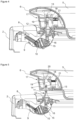
- The laundry washer and/or dryer realized in order to attain the aim of the present invention is illustrated in the attached figures, where:
-
Figure 1 - is the perspective view of the laundry washer and/or dryer related to an embodiment of the present invention. -
Figure 2 - is the partial cross-sectional view of the laundry washer and/or dryer related to an embodiment of the present invention, when the door is in the closed position. -
Figure 3 - is the partial cross-sectional view of the laundry washer and/or dryer related to an embodiment of the present invention, when the door is in the open position and the locking hook is on the door. -
Figure 4 - is the partial cross-sectional view of the laundry washer and/or dryer related to an embodiment of the present invention, when the actuation member is slid and the locking hook is released. -
Figure 5 - is the partial cross-sectional view of the laundry washer and/or dryer related to an embodiment of the present invention, when the door is in the open position and the locking hook is on the lock body. - The elements illustrated in the figures are numbered as follows:
- 1. Laundry washer and/or dryer
- 2. Body
- 3. Drum
- 4. Access opening
- 5. Door
- 6. Handle
- 7. Locking member
- 8. Lock body
- 9. Spring
- 10. Latch
- 11. Locking hook
- 12. Hook body
- 13. First hook
- 14. First locking housing
- 15. Second hook
- 16. Second locking housing
- 17. Actuation member
- 18. Resting surface
- 19. Sliding surface
- 20. Opening
- 21. Elastic member
- The laundry washer and/or dryer (1) comprises a body (2); a drum (3) which is disposed in the body (2) and wherein the laundry is loaded; an access opening (4) which is provided on the body (2) and which provides access into the drum (3); a door (5) which is attached to the body (2) by means of a hinge and which can move between an open position wherein the door (5) provides access into the drum (3) through the access opening (4) and a closed position wherein the door (5) closes the access opening (4); and a locking member (7) having a lock body (8) which is provided on the body (2), a latch (10) which is rotatably attached to the lock body (8), and a spring (9) which is attached to the latch (10) at one end and to the lock body (8) at the other end. After the laundry to be washed/dried is loaded into the drum (3), the door (5) is closed and the washing/drying process is performed. While the laundry washer and/or dryer (1) is in operation, the door (5) is locked and the laundry is enabled to remain in the drum (3) during the operation. The lock body (8) provided on the body (2) and the latch (10) rotatably attached to the lock body (8) enable the door (5) to be fixed to the body (2). The latch (10) can rotate and move between a lock position wherein the door (5) is locked and a free position wherein the door (5) is in the open position, and can move from the locked position back to the free position suitable for locking by means of the spring (9).
- The laundry washer and/or dryer (1) of the present invention comprises a locking hook (11) having a first hook (13) whereon a first locking housing (14) is provided and a second hook (15) whereon a second locking housing (16) engaging with the latch (10) when the door (5) is in the closed position is provided; an actuation member (17) which is provided on the door (5) and which is suitable to be moved by the user; and a resting surface (18) which is provided on the actuation member (17), which is fitted into the first locking housing (14) so as to enable the locking hook (11) to be connected to the door (5) and which enables the locking hook (11) to be released from the first locking housing (14) and separated from the door (5) when the actuation member (17) is moved. The actuation member (17) is configured to be slidably move on the door (5). While the door (5) is in the closed position, the actuation member (17) is moved so as to enable the locking hook (11) to be released from the resting surface (18). In this case, the door (5) is released from the locking hook (11) and becomes free. Thus, when the user wants to open the door(5), he/she can open the door (5) by simply sliding the actuation member (17), without having to pull the door (5) outward by applying a high force.
- In an embodiment of the present invention, the locking hook (11) has a hook body (12) and the first hook (13) and the second hook (15) which extend in directions opposite to each other over the hook body (12). The first hook (13) and the second hook (15) extend in the opposite direction to each other, on the same line. Thus, when a force in the direction of compressing or pulling is applied on the first hook (13) or the second hook (15), torsional loads do not occur on the hook body (12). Consequently, the hook body (12) can operate without bending and the economic life thereof is increased.
- In an embodiment of the present invention, the first locking housing (14) and the second locking housing (16) are positioned at an equal distance from the hook body (12). Thus, the stress generated in the hook body (12) is distributed more evenly towards the first locking housing (14) and the second locking housing (16). Consequently, stress accumulation in the hook body (12) is prevented and the economic life of the locking hook (11) is increased.
- In another embodiment of the present invention, the first hook (13) and the second hook (15) have the same form. The first hook (13) and the second hook (15) are configured to be mirror-symmetric. Thus, the locking hook (11) can be mounted from both directions, regardless of direction. Thus, the locking hook (11) can be mounted more easily and quickly.
- In another embodiment of the present invention, an elastic member (21), which compresses when the actuation member (17) is moved and applies force to the actuation member (17) in a direction opposite to the movement direction, is disposed between the actuation member (17) and the door (5). The elastic member (21) can be manufactured as a separate part or integrated with the actuation member (17). In this case, the actuation member (17) can return to its initial position with its own flexibility by resting directly on the door (5). The elastic member (21) compression spring can also be manufactured from rubber or a plastic material with elastic properties.
- In another embodiment of the present invention, a sliding surface (19) extending at an angle with respect to the first hook (13) is provided on the resting surface (18). The sliding surface (19) is provided on the actuation member (17) so as to contact the first hook (13) when the door (5) is being closed. When the door (5) is opened by triggering the actuation member (17), the locking hook (11) remains on the body (2). In this case, when the door (5) is brought to the closed position again, the first hook (13) bears against the sliding surface (19). The inclined sliding surface (19) enables the actuation member (17) to move more easily and the first hook (13) is seated on the resting surface (18). Thus, the door (5) is locked more quietly and securely.
- In another embodiment of the present invention, the sliding surface (19) is positioned at an angle of 30 to 60 degrees with respect to the resting surface (18). Thus, the door (5) can be closed with less force. In a preferred embodiment of the present invention, there is a 45 degree angle between the sliding surface (19) and the resting surface (18).
- In another embodiment of the present invention, a handle (6) suitable to be easily gripped by the user is provided on the door (5), and the actuation member (17) is placed on the door (5) so as to remain behind the handle (6). The handle (6) is configured to enable the users to better grasp the door (5). The actuation member (17) is positioned to be hidden behind the handle (6). Thus, formation of any inconvenient appearance is prevented.
- By means of the present invention, the door (5) of the laundry washer and/or dryer (1) is enabled to be opened/closed in an easy, quick and safe manner by means of actuation.
Claims (8)
- A laundry washer and/or dryer (1) comprising a body (2); a drum (3) which is disposed in the body (2) and wherein the laundry is loaded; an access opening (4) which is provided on the body (2) and which provides access into the drum (3); a door (5) which is attached to the body (2) by means of a hinge and which can move between an open position wherein the door (5) provides access into the drum (3) through the access opening (4) and a closed position wherein the door (5) closes the access opening (4); and a locking member (7) having a lock body (8) which is provided on the body (2), a latch (10) which is rotatably attached to the lock body (8), and a spring (9) which is attached to the latch (10) at one end and to the lock body (8) at the other end, characterized by a locking hook (11) having a first hook (13) whereon a first locking housing (14) is provided and a second hook (15) whereon a second locking housing (16) engaging with the latch (10) when the door (5) is in the closed position is provided; an actuation member (17) which is provided on the door (5) and which is suitable to be moved by the user; and a resting surface (18) which is provided on the actuation member (17), which is fitted into the first locking housing (14) so as to enable the locking hook (11) to be connected to the door (5) and which enables the locking hook (11) to be released from the first locking housing (14) and separated from the door (5) when the actuation member (17) is moved.
- A laundry washer and/or dryer (1) as in Claim 1, characterized by the locking hook (11) having a hook body (12) and the first hook (13) and the second hook (15) which extend in directions opposite to each other over the hook body (12).
- A laundry washer and/or dryer (1) as in Claim 2, characterized by the first locking housing (14) and the second locking housing (16) which are positioned at an equal distance from the hook body (12).
- A laundry washer and/or dryer (1) as in Claim 2 or Claim 3, characterized by the first hook (13) and the second hook (15) which have the same form.
- A laundry washer and/or dryer (1) as in any one of the above claims, characterized by an elastic member (21) which is disposed between the actuation member (17) and the door (5), which compresses when the actuation member (17) is moved and which applies force to the actuation member (17) in a direction opposite to the movement direction.
- A laundry washer and/or dryer (1) as in any one of the above claims, characterized by a sliding surface (19) which is provided on the resting surface (18) and which extends at an angle with respect to the first hook (13).
- A laundry washer and/or dryer (1) as in Claim 6, characterized by the sliding surface (19) which is positioned at an angle of 30 to 60 degrees with respect to the resting surface (18).
- A laundry washer and/or dryer (1) as in any one of the above claims, characterized by a handle (6) which is suitable to be easily gripped by the user is provided on the door (5), and the actuation member (17) which is placed on the door (5) so as to remain behind the handle (6).
Applications Claiming Priority (1)
| Application Number | Priority Date | Filing Date | Title |
|---|---|---|---|
| TR202305901 | 2023-05-24 |
Publications (2)
| Publication Number | Publication Date |
|---|---|
| EP4467705A1 true EP4467705A1 (en) | 2024-11-27 |
| EP4467705B1 EP4467705B1 (en) | 2025-12-10 |
Family
ID=90123081
Family Applications (1)
| Application Number | Title | Priority Date | Filing Date |
|---|---|---|---|
| EP24160469.3A Active EP4467705B1 (en) | 2023-05-24 | 2024-02-29 | A laundry washer and/or dryer comprising a door |
Country Status (1)
| Country | Link |
|---|---|
| EP (1) | EP4467705B1 (en) |
Citations (5)
| Publication number | Priority date | Publication date | Assignee | Title |
|---|---|---|---|---|
| US7306266B2 (en) | 2004-03-05 | 2007-12-11 | Illinois Tool Works, Inc. | Appliance latch having a rotating latch hook mounted on a linear slide |
| EP1972715B1 (en) | 2007-03-22 | 2009-10-21 | Elettrotecnica Rold Srl | Locking device for the closing lid of washing and drying machines |
| US20160230330A1 (en) * | 2015-02-10 | 2016-08-11 | Samsung Electronics Co., Ltd. | Clothing dryer |
| WO2019234985A1 (en) * | 2018-06-07 | 2019-12-12 | シャープ株式会社 | Cover lock mechanism and washing machine using same |
| US20220064991A1 (en) * | 2020-08-31 | 2022-03-03 | Emz-Hanauer Gmbh & Co. Kgaa | Domestic electrical appliance and door latch therefor |
-
2024
- 2024-02-29 EP EP24160469.3A patent/EP4467705B1/en active Active
Patent Citations (5)
| Publication number | Priority date | Publication date | Assignee | Title |
|---|---|---|---|---|
| US7306266B2 (en) | 2004-03-05 | 2007-12-11 | Illinois Tool Works, Inc. | Appliance latch having a rotating latch hook mounted on a linear slide |
| EP1972715B1 (en) | 2007-03-22 | 2009-10-21 | Elettrotecnica Rold Srl | Locking device for the closing lid of washing and drying machines |
| US20160230330A1 (en) * | 2015-02-10 | 2016-08-11 | Samsung Electronics Co., Ltd. | Clothing dryer |
| WO2019234985A1 (en) * | 2018-06-07 | 2019-12-12 | シャープ株式会社 | Cover lock mechanism and washing machine using same |
| US20220064991A1 (en) * | 2020-08-31 | 2022-03-03 | Emz-Hanauer Gmbh & Co. Kgaa | Domestic electrical appliance and door latch therefor |
Also Published As
| Publication number | Publication date |
|---|---|
| EP4467705B1 (en) | 2025-12-10 |
Similar Documents
| Publication | Publication Date | Title |
|---|---|---|
| RU2534056C1 (en) | Device for laundry processing | |
| KR100681570B1 (en) | Memory metal actuator in the door latch of the product | |
| EP2561168B1 (en) | Push-pull closing device | |
| KR101053624B1 (en) | Clothing processing device | |
| US11179020B2 (en) | Domestic appliance with door opener | |
| EP3983603B1 (en) | A washer/dryer comprising a lock | |
| CA2364792C (en) | Lid or door for household appliances | |
| CN113197536B (en) | Door lock device and household appliance equipped with such door lock device | |
| EP1972715A1 (en) | Locking device for the closing lid of washing and drying machines | |
| EP4467705B1 (en) | A laundry washer and/or dryer comprising a door | |
| US12467295B2 (en) | Push-push door latch and domestic electrical appliance equipped therewith | |
| EP2929077B1 (en) | Laundry treatment device with door assembly | |
| EP0917853B1 (en) | Door locking arrangement for a household appliance, such as for example a dishwashing machine | |
| CN222295976U (en) | Safety door lock for household appliances | |
| US12096901B2 (en) | Door lock for a household appliance and household appliance having the door lock | |
| KR20050111042A (en) | Door locking switch of washing machine | |
| CN115977477B (en) | Household appliance door lock | |
| WO2005042891A1 (en) | Domestic appliance with two directional hinge | |
| KR102771815B1 (en) | Door-lock device for household appliances and household appliance comprising said device | |
| KR960002302B1 (en) | Household appliance fastening device particularly for a washing machine | |
| TR2023005901A2 (en) | A WASHER AND/OR DRYER WITH A COVER | |
| CN121428792A (en) | Locking devices for doors used in household appliances | |
| KR101176134B1 (en) | Door switch for washing machine | |
| CN223867801U (en) | Door lock capable of realizing self-resetting function by using torsion spring | |
| EP2540899B1 (en) | A machine for treating laudry |
Legal Events
| Date | Code | Title | Description |
|---|---|---|---|
| PUAI | Public reference made under article 153(3) epc to a published international application that has entered the european phase |
Free format text: ORIGINAL CODE: 0009012 |
|
| STAA | Information on the status of an ep patent application or granted ep patent |
Free format text: STATUS: REQUEST FOR EXAMINATION WAS MADE |
|
| 17P | Request for examination filed |
Effective date: 20240229 |
|
| AK | Designated contracting states |
Kind code of ref document: A1 Designated state(s): AL AT BE BG CH CY CZ DE DK EE ES FI FR GB GR HR HU IE IS IT LI LT LU LV MC ME MK MT NL NO PL PT RO RS SE SI SK SM TR |
|
| GRAP | Despatch of communication of intention to grant a patent |
Free format text: ORIGINAL CODE: EPIDOSNIGR1 |
|
| STAA | Information on the status of an ep patent application or granted ep patent |
Free format text: STATUS: GRANT OF PATENT IS INTENDED |
|
| RIC1 | Information provided on ipc code assigned before grant |
Ipc: D06F 37/42 20060101AFI20250709BHEP Ipc: D06F 39/14 20060101ALI20250709BHEP Ipc: D06F 58/04 20060101ALN20250709BHEP |
|
| RIC1 | Information provided on ipc code assigned before grant |
Ipc: D06F 37/42 20060101AFI20250716BHEP Ipc: D06F 39/14 20060101ALI20250716BHEP Ipc: D06F 58/04 20060101ALN20250716BHEP |
|
| INTG | Intention to grant announced |
Effective date: 20250730 |
|
| GRAS | Grant fee paid |
Free format text: ORIGINAL CODE: EPIDOSNIGR3 |
|
| GRAA | (expected) grant |
Free format text: ORIGINAL CODE: 0009210 |
|
| STAA | Information on the status of an ep patent application or granted ep patent |
Free format text: STATUS: THE PATENT HAS BEEN GRANTED |
|
| AK | Designated contracting states |
Kind code of ref document: B1 Designated state(s): AL AT BE BG CH CY CZ DE DK EE ES FI FR GB GR HR HU IE IS IT LI LT LU LV MC ME MK MT NL NO PL PT RO RS SE SI SK SM TR |
|
| REG | Reference to a national code |
Ref country code: CH Ref legal event code: F10 Free format text: ST27 STATUS EVENT CODE: U-0-0-F10-F00 (AS PROVIDED BY THE NATIONAL OFFICE) Effective date: 20251210 Ref country code: GB Ref legal event code: FG4D |
|
| REG | Reference to a national code |
Ref country code: DE Ref legal event code: R096 Ref document number: 602024001561 Country of ref document: DE Ref country code: IE Ref legal event code: FG4D |
|
| PG25 | Lapsed in a contracting state [announced via postgrant information from national office to epo] |
Ref country code: ES Free format text: LAPSE BECAUSE OF FAILURE TO SUBMIT A TRANSLATION OF THE DESCRIPTION OR TO PAY THE FEE WITHIN THE PRESCRIBED TIME-LIMIT Effective date: 20251210 |
|
| REG | Reference to a national code |
Ref country code: LT Ref legal event code: MG9D |
|
| PG25 | Lapsed in a contracting state [announced via postgrant information from national office to epo] |
Ref country code: NO Free format text: LAPSE BECAUSE OF FAILURE TO SUBMIT A TRANSLATION OF THE DESCRIPTION OR TO PAY THE FEE WITHIN THE PRESCRIBED TIME-LIMIT Effective date: 20260310 |
|
| PGFP | Annual fee paid to national office [announced via postgrant information from national office to epo] |
Ref country code: DE Payment date: 20260319 Year of fee payment: 3 |
|
| PG25 | Lapsed in a contracting state [announced via postgrant information from national office to epo] |
Ref country code: FI Free format text: LAPSE BECAUSE OF FAILURE TO SUBMIT A TRANSLATION OF THE DESCRIPTION OR TO PAY THE FEE WITHIN THE PRESCRIBED TIME-LIMIT Effective date: 20251210 Ref country code: HR Free format text: LAPSE BECAUSE OF FAILURE TO SUBMIT A TRANSLATION OF THE DESCRIPTION OR TO PAY THE FEE WITHIN THE PRESCRIBED TIME-LIMIT Effective date: 20251210 |
|
| PGFP | Annual fee paid to national office [announced via postgrant information from national office to epo] |
Ref country code: IT Payment date: 20260228 Year of fee payment: 3 |
|
| REG | Reference to a national code |
Ref country code: NL Ref legal event code: MP Effective date: 20251210 |
|
| PG25 | Lapsed in a contracting state [announced via postgrant information from national office to epo] |
Ref country code: RS Free format text: LAPSE BECAUSE OF FAILURE TO SUBMIT A TRANSLATION OF THE DESCRIPTION OR TO PAY THE FEE WITHIN THE PRESCRIBED TIME-LIMIT Effective date: 20260310 |
|
| PGFP | Annual fee paid to national office [announced via postgrant information from national office to epo] |
Ref country code: TR Payment date: 20260225 Year of fee payment: 3 |
|
| PG25 | Lapsed in a contracting state [announced via postgrant information from national office to epo] |
Ref country code: LV Free format text: LAPSE BECAUSE OF FAILURE TO SUBMIT A TRANSLATION OF THE DESCRIPTION OR TO PAY THE FEE WITHIN THE PRESCRIBED TIME-LIMIT Effective date: 20251210 |
|
| PG25 | Lapsed in a contracting state [announced via postgrant information from national office to epo] |
Ref country code: BG Free format text: LAPSE BECAUSE OF FAILURE TO SUBMIT A TRANSLATION OF THE DESCRIPTION OR TO PAY THE FEE WITHIN THE PRESCRIBED TIME-LIMIT Effective date: 20251210 |
|
| REG | Reference to a national code |
Ref country code: AT Ref legal event code: MK05 Ref document number: 1866251 Country of ref document: AT Kind code of ref document: T Effective date: 20251210 |
|
| PG25 | Lapsed in a contracting state [announced via postgrant information from national office to epo] |
Ref country code: NL Free format text: LAPSE BECAUSE OF FAILURE TO SUBMIT A TRANSLATION OF THE DESCRIPTION OR TO PAY THE FEE WITHIN THE PRESCRIBED TIME-LIMIT Effective date: 20251210 |
|
| PG25 | Lapsed in a contracting state [announced via postgrant information from national office to epo] |
Ref country code: LT Free format text: LAPSE BECAUSE OF FAILURE TO SUBMIT A TRANSLATION OF THE DESCRIPTION OR TO PAY THE FEE WITHIN THE PRESCRIBED TIME-LIMIT Effective date: 20251210 |
|
| PG25 | Lapsed in a contracting state [announced via postgrant information from national office to epo] |
Ref country code: SM Free format text: LAPSE BECAUSE OF FAILURE TO SUBMIT A TRANSLATION OF THE DESCRIPTION OR TO PAY THE FEE WITHIN THE PRESCRIBED TIME-LIMIT Effective date: 20251210 |
|
| PG25 | Lapsed in a contracting state [announced via postgrant information from national office to epo] |
Ref country code: PL Free format text: LAPSE BECAUSE OF FAILURE TO SUBMIT A TRANSLATION OF THE DESCRIPTION OR TO PAY THE FEE WITHIN THE PRESCRIBED TIME-LIMIT Effective date: 20251210 |
|
| PG25 | Lapsed in a contracting state [announced via postgrant information from national office to epo] |
Ref country code: AT Free format text: LAPSE BECAUSE OF FAILURE TO SUBMIT A TRANSLATION OF THE DESCRIPTION OR TO PAY THE FEE WITHIN THE PRESCRIBED TIME-LIMIT Effective date: 20251210 |
|
| PG25 | Lapsed in a contracting state [announced via postgrant information from national office to epo] |
Ref country code: EE Free format text: LAPSE BECAUSE OF FAILURE TO SUBMIT A TRANSLATION OF THE DESCRIPTION OR TO PAY THE FEE WITHIN THE PRESCRIBED TIME-LIMIT Effective date: 20251210 |
|
| PG25 | Lapsed in a contracting state [announced via postgrant information from national office to epo] |
Ref country code: PT Free format text: LAPSE BECAUSE OF FAILURE TO SUBMIT A TRANSLATION OF THE DESCRIPTION OR TO PAY THE FEE WITHIN THE PRESCRIBED TIME-LIMIT Effective date: 20260410 Ref country code: IS Free format text: LAPSE BECAUSE OF FAILURE TO SUBMIT A TRANSLATION OF THE DESCRIPTION OR TO PAY THE FEE WITHIN THE PRESCRIBED TIME-LIMIT Effective date: 20260410 |
|
| PG25 | Lapsed in a contracting state [announced via postgrant information from national office to epo] |
Ref country code: CZ Free format text: LAPSE BECAUSE OF FAILURE TO SUBMIT A TRANSLATION OF THE DESCRIPTION OR TO PAY THE FEE WITHIN THE PRESCRIBED TIME-LIMIT Effective date: 20251210 |
|
| PG25 | Lapsed in a contracting state [announced via postgrant information from national office to epo] |
Ref country code: SK Free format text: LAPSE BECAUSE OF FAILURE TO SUBMIT A TRANSLATION OF THE DESCRIPTION OR TO PAY THE FEE WITHIN THE PRESCRIBED TIME-LIMIT Effective date: 20251210 |
|
| PG25 | Lapsed in a contracting state [announced via postgrant information from national office to epo] |
Ref country code: SE Free format text: LAPSE BECAUSE OF FAILURE TO SUBMIT A TRANSLATION OF THE DESCRIPTION OR TO PAY THE FEE WITHIN THE PRESCRIBED TIME-LIMIT Effective date: 20251210 |