EP4467703A1 - Clothing processing apparatus and method for controlling clothing processing apparatus - Google Patents
Clothing processing apparatus and method for controlling clothing processing apparatus Download PDFInfo
- Publication number
- EP4467703A1 EP4467703A1 EP22924339.9A EP22924339A EP4467703A1 EP 4467703 A1 EP4467703 A1 EP 4467703A1 EP 22924339 A EP22924339 A EP 22924339A EP 4467703 A1 EP4467703 A1 EP 4467703A1
- Authority
- EP
- European Patent Office
- Prior art keywords
- tub
- water level
- capacitance
- drum
- water
- Prior art date
- Legal status (The legal status is an assumption and is not a legal conclusion. Google has not performed a legal analysis and makes no representation as to the accuracy of the status listed.)
- Pending
Links
- 238000000034 method Methods 0.000 title claims description 58
- XLYOFNOQVPJJNP-UHFFFAOYSA-N water Substances O XLYOFNOQVPJJNP-UHFFFAOYSA-N 0.000 claims abstract description 225
- 239000006260 foam Substances 0.000 claims abstract description 59
- 239000003599 detergent Substances 0.000 claims abstract description 39
- 238000005406 washing Methods 0.000 claims description 30
- 239000000126 substance Substances 0.000 claims description 12
- 230000001939 inductive effect Effects 0.000 claims description 8
- 230000007423 decrease Effects 0.000 claims description 2
- 238000010586 diagram Methods 0.000 description 4
- 238000007599 discharging Methods 0.000 description 3
- 238000001035 drying Methods 0.000 description 2
- 239000000463 material Substances 0.000 description 2
- 230000005540 biological transmission Effects 0.000 description 1
- 230000003111 delayed effect Effects 0.000 description 1
- 230000000694 effects Effects 0.000 description 1
Images

Classifications
-
- D—TEXTILES; PAPER
- D06—TREATMENT OF TEXTILES OR THE LIKE; LAUNDERING; FLEXIBLE MATERIALS NOT OTHERWISE PROVIDED FOR
- D06F—LAUNDERING, DRYING, IRONING, PRESSING OR FOLDING TEXTILE ARTICLES
- D06F39/00—Details of washing machines not specific to a single type of machines covered by groups D06F9/00 - D06F27/00
- D06F39/08—Liquid supply or discharge arrangements
- D06F39/088—Liquid supply arrangements
-
- D—TEXTILES; PAPER
- D06—TREATMENT OF TEXTILES OR THE LIKE; LAUNDERING; FLEXIBLE MATERIALS NOT OTHERWISE PROVIDED FOR
- D06F—LAUNDERING, DRYING, IRONING, PRESSING OR FOLDING TEXTILE ARTICLES
- D06F33/00—Control of operations performed in washing machines or washer-dryers
- D06F33/30—Control of washing machines characterised by the purpose or target of the control
- D06F33/47—Responding to irregular working conditions, e.g. malfunctioning of pumps
-
- D—TEXTILES; PAPER
- D06—TREATMENT OF TEXTILES OR THE LIKE; LAUNDERING; FLEXIBLE MATERIALS NOT OTHERWISE PROVIDED FOR
- D06F—LAUNDERING, DRYING, IRONING, PRESSING OR FOLDING TEXTILE ARTICLES
- D06F34/00—Details of control systems for washing machines, washer-dryers or laundry dryers
- D06F34/14—Arrangements for detecting or measuring specific parameters
-
- D—TEXTILES; PAPER
- D06—TREATMENT OF TEXTILES OR THE LIKE; LAUNDERING; FLEXIBLE MATERIALS NOT OTHERWISE PROVIDED FOR
- D06F—LAUNDERING, DRYING, IRONING, PRESSING OR FOLDING TEXTILE ARTICLES
- D06F35/00—Washing machines, apparatus, or methods not otherwise provided for
- D06F35/005—Methods for washing, rinsing or spin-drying
-
- D—TEXTILES; PAPER
- D06—TREATMENT OF TEXTILES OR THE LIKE; LAUNDERING; FLEXIBLE MATERIALS NOT OTHERWISE PROVIDED FOR
- D06F—LAUNDERING, DRYING, IRONING, PRESSING OR FOLDING TEXTILE ARTICLES
- D06F37/00—Details specific to washing machines covered by groups D06F21/00 - D06F25/00
- D06F37/30—Driving arrangements
- D06F37/304—Arrangements or adaptations of electric motors
-
- D—TEXTILES; PAPER
- D06—TREATMENT OF TEXTILES OR THE LIKE; LAUNDERING; FLEXIBLE MATERIALS NOT OTHERWISE PROVIDED FOR
- D06F—LAUNDERING, DRYING, IRONING, PRESSING OR FOLDING TEXTILE ARTICLES
- D06F39/00—Details of washing machines not specific to a single type of machines covered by groups D06F9/00 - D06F27/00
- D06F39/02—Devices for adding soap or other washing agents
-
- D—TEXTILES; PAPER
- D06—TREATMENT OF TEXTILES OR THE LIKE; LAUNDERING; FLEXIBLE MATERIALS NOT OTHERWISE PROVIDED FOR
- D06F—LAUNDERING, DRYING, IRONING, PRESSING OR FOLDING TEXTILE ARTICLES
- D06F39/00—Details of washing machines not specific to a single type of machines covered by groups D06F9/00 - D06F27/00
- D06F39/06—Arrangements for preventing or destroying scum
-
- D—TEXTILES; PAPER
- D06—TREATMENT OF TEXTILES OR THE LIKE; LAUNDERING; FLEXIBLE MATERIALS NOT OTHERWISE PROVIDED FOR
- D06F—LAUNDERING, DRYING, IRONING, PRESSING OR FOLDING TEXTILE ARTICLES
- D06F39/00—Details of washing machines not specific to a single type of machines covered by groups D06F9/00 - D06F27/00
- D06F39/08—Liquid supply or discharge arrangements
-
- D—TEXTILES; PAPER
- D06—TREATMENT OF TEXTILES OR THE LIKE; LAUNDERING; FLEXIBLE MATERIALS NOT OTHERWISE PROVIDED FOR
- D06F—LAUNDERING, DRYING, IRONING, PRESSING OR FOLDING TEXTILE ARTICLES
- D06F39/00—Details of washing machines not specific to a single type of machines covered by groups D06F9/00 - D06F27/00
- D06F39/08—Liquid supply or discharge arrangements
- D06F39/087—Water level measuring or regulating devices
-
- D—TEXTILES; PAPER
- D06—TREATMENT OF TEXTILES OR THE LIKE; LAUNDERING; FLEXIBLE MATERIALS NOT OTHERWISE PROVIDED FOR
- D06F—LAUNDERING, DRYING, IRONING, PRESSING OR FOLDING TEXTILE ARTICLES
- D06F2103/00—Parameters monitored or detected for the control of domestic laundry washing machines, washer-dryers or laundry dryers
- D06F2103/18—Washing liquid level
-
- D—TEXTILES; PAPER
- D06—TREATMENT OF TEXTILES OR THE LIKE; LAUNDERING; FLEXIBLE MATERIALS NOT OTHERWISE PROVIDED FOR
- D06F—LAUNDERING, DRYING, IRONING, PRESSING OR FOLDING TEXTILE ARTICLES
- D06F2105/00—Systems or parameters controlled or affected by the control systems of washing machines, washer-dryers or laundry dryers
- D06F2105/02—Water supply
-
- D—TEXTILES; PAPER
- D06—TREATMENT OF TEXTILES OR THE LIKE; LAUNDERING; FLEXIBLE MATERIALS NOT OTHERWISE PROVIDED FOR
- D06F—LAUNDERING, DRYING, IRONING, PRESSING OR FOLDING TEXTILE ARTICLES
- D06F2105/00—Systems or parameters controlled or affected by the control systems of washing machines, washer-dryers or laundry dryers
- D06F2105/08—Draining of washing liquids
-
- D—TEXTILES; PAPER
- D06—TREATMENT OF TEXTILES OR THE LIKE; LAUNDERING; FLEXIBLE MATERIALS NOT OTHERWISE PROVIDED FOR
- D06F—LAUNDERING, DRYING, IRONING, PRESSING OR FOLDING TEXTILE ARTICLES
- D06F2105/00—Systems or parameters controlled or affected by the control systems of washing machines, washer-dryers or laundry dryers
- D06F2105/52—Changing sequence of operational steps; Carrying out additional operational steps; Modifying operational steps, e.g. by extending duration of steps
-
- D—TEXTILES; PAPER
- D06—TREATMENT OF TEXTILES OR THE LIKE; LAUNDERING; FLEXIBLE MATERIALS NOT OTHERWISE PROVIDED FOR
- D06F—LAUNDERING, DRYING, IRONING, PRESSING OR FOLDING TEXTILE ARTICLES
- D06F33/00—Control of operations performed in washing machines or washer-dryers
- D06F33/30—Control of washing machines characterised by the purpose or target of the control
- D06F33/32—Control of operational steps, e.g. optimisation or improvement of operational steps depending on the condition of the laundry
- D06F33/34—Control of operational steps, e.g. optimisation or improvement of operational steps depending on the condition of the laundry of water filling
-
- D—TEXTILES; PAPER
- D06—TREATMENT OF TEXTILES OR THE LIKE; LAUNDERING; FLEXIBLE MATERIALS NOT OTHERWISE PROVIDED FOR
- D06F—LAUNDERING, DRYING, IRONING, PRESSING OR FOLDING TEXTILE ARTICLES
- D06F33/00—Control of operations performed in washing machines or washer-dryers
- D06F33/30—Control of washing machines characterised by the purpose or target of the control
- D06F33/32—Control of operational steps, e.g. optimisation or improvement of operational steps depending on the condition of the laundry
- D06F33/38—Control of operational steps, e.g. optimisation or improvement of operational steps depending on the condition of the laundry of rinsing
-
- D—TEXTILES; PAPER
- D06—TREATMENT OF TEXTILES OR THE LIKE; LAUNDERING; FLEXIBLE MATERIALS NOT OTHERWISE PROVIDED FOR
- D06F—LAUNDERING, DRYING, IRONING, PRESSING OR FOLDING TEXTILE ARTICLES
- D06F33/00—Control of operations performed in washing machines or washer-dryers
- D06F33/30—Control of washing machines characterised by the purpose or target of the control
- D06F33/32—Control of operational steps, e.g. optimisation or improvement of operational steps depending on the condition of the laundry
- D06F33/42—Control of operational steps, e.g. optimisation or improvement of operational steps depending on the condition of the laundry of draining
-
- D—TEXTILES; PAPER
- D06—TREATMENT OF TEXTILES OR THE LIKE; LAUNDERING; FLEXIBLE MATERIALS NOT OTHERWISE PROVIDED FOR
- D06F—LAUNDERING, DRYING, IRONING, PRESSING OR FOLDING TEXTILE ARTICLES
- D06F37/00—Details specific to washing machines covered by groups D06F21/00 - D06F25/00
- D06F37/02—Rotary receptacles, e.g. drums
- D06F37/04—Rotary receptacles, e.g. drums adapted for rotation or oscillation about a horizontal or inclined axis
Definitions
- the present application relates to a laundry treatment apparatus and method of controlling the same.
- a laundry treatment device conceptually includes a washing machine for washing a washing object such as laundry and the like and a dryer for drying a drying object.
- the laundry treatment device with the aforementioned structure performs washing in a manner of repeating a foreign substance separating process of removing foreign substances remaining in a washing object by rotating the drum after supplying water and detergent to the tub through the water supply unit and the detergent supply unit, a draining process of discharging the water stored in the tub, and a dewatering process of removing water remaining in the washing object by rotating the drum.
- Foam is generated inside the tub during the foreign substance separating process, and the related art laundry treatment devices have a structure that is difficult to measure or predict an amount of the foam generated inside the tub.
- the foam generated in the foreign substance separating process causes a problem of discharging the foam to the outside of the tub, a problem of causing a large load on the driving unit rotating the drum, and a problem of having difficulty in rotating the drum at a high rotational speed required for the dewatering process.
- One technical task of the present application is to provide an apparatus for treating laundry and method of controlling the same that may determine a water level inside a tub and an amount of foam generated inside the tub (such as a height of the foam, etc.).
- another technical aspect of the present application is to provide an apparatus for treating laundry and method of controlling the same that include an electrostatic sensor capable of measuring a water level inside a tub and an amount of foam generated inside the tub in real time.
- an apparatus for treating laundry including a tub having a tub body providing a space for storing water and a tub entrance perforating one surface of the tub body, a drum having a drum body rotatably provided within the tub to store the laundry and a drum entrance perforating one surface of the drum body to communicate with the tub entrance, a water supply unit supplying water to the tub, a detergent supply unit supplying detergent to the tub, and a sensor detecting a change in capacitance inside the tub body to sense at least one of a height of foam generated within the tub body or a height of the water stored in the tub body.
- the tub body may be provided as a cylinder in a hollow shape having a central axis parallel to a ground, the tub entrance may be provided in any one of a front surface or a rear surface of the cylinder, and the sensor may be fixed to at least one of the front surface or the rear surface.
- the tub body may be provided as a cylinder in a hollow shape having a central axis orthogonal to a ground, the tub entrance may be provided in an upper surface of the cylinder, and the sensor may be fixed to at least one of the upper surface and an area in a circumferential surface of the tub body located above a horizontal line passing through a center of the tub body.
- the tub body may be provided as a cylinder in a hollow shape having a central axis inclined at an angle of less than 90 degrees with respect to a ground, the tub entrance may be provided in a front surface of the cylinder, and the sensor may be fixed to the front surface.
- the sensor may be fixed at a position capable of determining whether the foam within the tub body has reached a preset reference height.
- the apparatus may further include a driving unit providing a motive power necessary for rotation of the drum, and the reference height may be set to a height of the foam at which a rotational speed of the drum becomes lower than a set speed by 10% or more when a power of a preset reference power amount is supplied to the driving unit.
- the reference height may be set to a multitude of heights corresponding to a multitude of reference water levels set to increase in proportion to an amount of the laundry put into the drum and the number of the sensors may be equal to the number of the reference heights.
- the reference water level may include a lowest water level set to a water level at which a lowest point of a circumferential surface of the drum body is submerged, a highest water level located at a point higher than the lowest water level and lower than a horizontal line passing through a center of the tub entrance, and an intermediate water level located between the lowest water level and the highest water level
- the reference height may include a first reference height positioned between the lowest water level and the intermediate water level, a second reference height positioned between the intermediate water level and the highest water level, and a third reference height positioned at a point higher than the highest water level
- the sensor may include a first sensor fixed to the front surface and positioned at the first reference height, a second sensor positioned at the second reference height, and a third sensor positioned at the third reference height.
- the reference water level may include a lowest water level set to a water level at which a lowest point of a circumferential surface of the drum body is submerged and an intermediate water level set to a water level higher than the lowest water level
- the reference height may include a first reference height positioned between the lowest water level and the intermediate water level and a second reference height positioned at a point higher than the intermediate water level
- the sensor may include a first sensor fixed to the front surface and positioned at the first reference height and a second sensor positioned at the second reference height.
- the sensor may be fixed at a position capable of determining whether a water level inside the tub body reaches a reference water level.
- the reference water level may include a lowest water level set to a water level at which a lowest point of a circumferential surface of the drum body is submerged, a highest water level located at a point higher than the lowest water level and lower than a horizontal line passing through a center of the tub entrance, and an intermediate water level located between the lowest water level and the highest water level, and the sensor may include a first sensor positioned at the same height as the lowest water level, a second sensor positioned at the same height as the intermediate water level, and a third sensor positioned at the same height as the highest water level.
- the reference water level may include a lowest water level set to a water level at which a lowest point of a circumferential surface of the drum body is submerged and an intermediate water level set to a water level higher than the lowest water level, and the sensor may include a first sensor positioned at the same height as the lowest water level and a second sensor positioned at the same height as the intermediate water level.
- a method of controlling a laundry treating apparatus comprising a tub providing a space for storing water, a drum rotatably provided in the tub to store laundry, a water supply unit supplying water to the tub, a detergent supply unit supplying detergent to the tub, and a sensor detecting a change in capacitance inside a tub body to sense at least one of a height of foam generated inside the tub body or a height of water stored in the tub body, the method including a laundry amount detecting step of determine an amount of the laundry stored in the drum by rotating the drum, a water supply step of supplying the water to the tub through a water supply unit according to a laundry amount, a detergent supply step of supplying the detergent to the tub by the detergent supply unit, a washing step of removing foreign substances from the laundry by rotating the drum, and a measuring step of measuring by the sensor whether capacitance inside the tub body has increased and a time for which the capacitance has continued to increase during the washing step.
- the washing step may decrease a rotational speed of the drum.
- the washing step may be configured to alternately execute clockwise rotation and counterclockwise rotation of the drum.
- the washing step may set a rotation direction change period of the drum to be long.
- the method may further include an intermediate drain step of draining the water stored in the tub when the capacitance inside the tub body is equal to or greater than a reference capacitance and a state in which the capacitance is greater than or equal to the reference capacitance continues for more than a second reference time longer than the first reference time and a water resupply step of supplying water to the tub after completion of the intermediate drain step.
- the method may further include an observation motion executing step of rotating the drum at a rotational speed of inducing a centrifugal force less than 1G in either a clockwise direction or a counterclockwise direction, the observation motion executing step executed in progress of the washing step, a draining step of draining the water stored in the tub when the capacitance measured by the sensor in progress of the observation motion executing step is less than a reference capacitance or a holding time of a state in which the capacitance is equal to or greater than the reference capacitance is less than a preset third reference time, a dewatering step of removing water from the laundry by rotating the drum at a rotational speed of inducing a centrifugal force equal to or greater than 1G, and a rinsing step of separating the detergent and foreign substances from the laundry by rotating the drum at a rotational speed of inducing the centrifugal force less than 1G after supplying water to the tub after completion of the dewatering step.
- the method may further include a draining step of draining the water stored in the tub when the capacitance measured by the sensor in progress of the observation motion executing step is equal to or greater than the reference capacitance and a holding time of a state in which the capacitance is greater than or equal to the reference capacitance is greater than or equal to the third reference time and a rinsing step of separating the detergent and foreign substances from the laundry by rotating the drum after supplying water to the tub.
- the method may further include a draining step of draining the water stored in the tub when the capacitance measured by the sensor in progress of the observation motion executing step is equal to or greater than the reference capacitance and a holding time of a state in which the capacitance is greater than or equal to the reference capacitance is greater than or equal to the third reference time, a foam removing step of simultaneously executing a process of supplying the water to the tub by the water supply unit and a process of draining the water supplied to the tub by a drain unit, and a dewatering step of removing water from the laundry by rotating the drum at a rotational speed of inducing the centrifugal force equal to or greater 1G based on completing the foam removing step.
- the present application provides an apparatus for treating laundry and method of controlling the same that may determine a water level inside a tub and an amount of foam generated inside the tub (such as a height of the foam).
- the present application provides an apparatus for treating laundry and method of controlling the same that include an electrostatic sensor capable of determining at least one of a water level inside a tub and an amount of foam generated inside the tub.
- the present application provides an apparatus for treating laundry and method of controlling the same that include an electrostatic sensor capable of measuring a water level inside a tub and an amount of foam generated inside the tub in real time.
- a laundry treating apparatus 100 includes a cabinet 1, a tub 2 provided inside the cabinet to provide a space for storing water, and a drum 3 rotatably provided inside the tub to store laundry.
- the cabinet 1 is provided to include a front panel 11 forming a front surface of the laundry treating apparatus, and the front panel 11 is provided with an entrance 12 allowing the inside of the cabinet to communicate with the outside.
- the entrance 12 may be provided to be opened and closed by a door 13 rotatably provided on the front panel 11.
- the tub 2 may be provided as a cylindrical tub body 21 of which inside is hollow.
- a tub entrance 23 is provided at any one of a front surface 22 (i.e., a tub front surface) and a rear surface 26 (i.e., a tub rear surface) of the tub body 21.
- the diagram illustrates a case in which a tub entrance 23 is provided at the tub front surface 22.
- the observation motion executing step S50 is a step of executing an observation motion (e.g., a tumbling motion) in which the drum 3 is rotated at a rotational speed at which a centrifugal force of less than 1 G is induced only in one of a clockwise direction and a counterclockwise direction.
- an observation motion e.g., a tumbling motion
- the control method may sequentially execute a draining step S70, a dewatering step S80, and a rinsing step S90.
- the control method may execute only the draining step S62 and the rinsing step S90 while omitting the dewatering step S80.
- the control method is characterized in that the draining step S62, the foam removing step S63, the dewatering step S80, and the rinsing step S90 are sequentially executed.
- the draining step S62, the dewatering step S80, and the rinsing step S90 may be provided in the same manner as the draining step, the dewatering step, and the rinsing step provided in the control method of FIG. 3 .
- the foam removing step S63 may be provided as a step of simultaneously executing a process in which the water supply unit 4 supplies water to the tub 2 and a process in which the drain unit 6 drains the water supplied to the tub 2.
- the foam inside the tub may be discharged to the outside of the tub, so the control method according to the present embodiment may reduce the possibility of an error occurring due to the foam when executing the dewatering step S80.
Landscapes
- Engineering & Computer Science (AREA)
- Textile Engineering (AREA)
- Control Of Washing Machine And Dryer (AREA)
Abstract
Description
- The present application relates to a laundry treatment apparatus and method of controlling the same.
- In general, a laundry treatment device conceptually includes a washing machine for washing a washing object such as laundry and the like and a dryer for drying a drying object.
- The related art laundry treatment devices for washing are provided to include a tub providing a space for water storage, a drum rotatably provided within the tube to store a washing object, a water supply unit supplying water to the tub, a detergent supply unit supplying detergent to the tub, and a drain unit discharging water stored in the tub to the outside of the tub.
- The laundry treatment device with the aforementioned structure performs washing in a manner of repeating a foreign substance separating process of removing foreign substances remaining in a washing object by rotating the drum after supplying water and detergent to the tub through the water supply unit and the detergent supply unit, a draining process of discharging the water stored in the tub, and a dewatering process of removing water remaining in the washing object by rotating the drum.
- Foam is generated inside the tub during the foreign substance separating process, and the related art laundry treatment devices have a structure that is difficult to measure or predict an amount of the foam generated inside the tub.
- The foam generated in the foreign substance separating process causes a problem of discharging the foam to the outside of the tub, a problem of causing a large load on the driving unit rotating the drum, and a problem of having difficulty in rotating the drum at a high rotational speed required for the dewatering process.
- Regarding the related art laundry treatment devices, there is a method of detecting foam through a change in the number of revolutions of the drum or a torque variation of the driving unit above (e.g., a torque variation of the motor) (Publication No.
10-2000-0025493 10-2006-0115264 - One technical task of the present application is to provide an apparatus for treating laundry and method of controlling the same that may determine a water level inside a tub and an amount of foam generated inside the tub (such as a height of the foam, etc.).
- In addition, another technical task of the present application is to provide an apparatus for treating laundry and method of controlling the same that include an electrostatic sensor capable of determining at least one of a water level inside a tub and an amount of foam generated inside the tub.
- In addition, another technical aspect of the present application is to provide an apparatus for treating laundry and method of controlling the same that include an electrostatic sensor capable of measuring a water level inside a tub and an amount of foam generated inside the tub in real time.
- In one technical aspect of the present application, provided is an apparatus for treating laundry, the apparatus including a tub having a tub body providing a space for storing water and a tub entrance perforating one surface of the tub body, a drum having a drum body rotatably provided within the tub to store the laundry and a drum entrance perforating one surface of the drum body to communicate with the tub entrance, a water supply unit supplying water to the tub, a detergent supply unit supplying detergent to the tub, and a sensor detecting a change in capacitance inside the tub body to sense at least one of a height of foam generated within the tub body or a height of the water stored in the tub body.
- The tub body may be provided as a cylinder in a hollow shape having a central axis parallel to a ground, the tub entrance may be provided in any one of a front surface or a rear surface of the cylinder, and the sensor may be fixed to at least one of the front surface or the rear surface.
- The tub body may be provided as a cylinder in a hollow shape having a central axis orthogonal to a ground, the tub entrance may be provided in an upper surface of the cylinder, and the sensor may be fixed to at least one of the upper surface and an area in a circumferential surface of the tub body located above a horizontal line passing through a center of the tub body.
- The tub body may be provided as a cylinder in a hollow shape having a central axis inclined at an angle of less than 90 degrees with respect to a ground, the tub entrance may be provided in a front surface of the cylinder, and the sensor may be fixed to the front surface.
- The sensor may be fixed at a position capable of determining whether the foam within the tub body has reached a preset reference height.
- The apparatus may further include a driving unit providing a motive power necessary for rotation of the drum, and the reference height may be set to a height of the foam at which a rotational speed of the drum becomes lower than a set speed by 10% or more when a power of a preset reference power amount is supplied to the driving unit.
- The reference height may be set to a multitude of heights corresponding to a multitude of reference water levels set to increase in proportion to an amount of the laundry put into the drum and the number of the sensors may be equal to the number of the reference heights.
- The reference water level may include a lowest water level set to a water level at which a lowest point of a circumferential surface of the drum body is submerged, a highest water level located at a point higher than the lowest water level and lower than a horizontal line passing through a center of the tub entrance, and an intermediate water level located between the lowest water level and the highest water level, the reference height may include a first reference height positioned between the lowest water level and the intermediate water level, a second reference height positioned between the intermediate water level and the highest water level, and a third reference height positioned at a point higher than the highest water level, and the sensor may include a first sensor fixed to the front surface and positioned at the first reference height, a second sensor positioned at the second reference height, and a third sensor positioned at the third reference height.
- The reference water level may include a lowest water level set to a water level at which a lowest point of a circumferential surface of the drum body is submerged and an intermediate water level set to a water level higher than the lowest water level, the reference height may include a first reference height positioned between the lowest water level and the intermediate water level and a second reference height positioned at a point higher than the intermediate water level, and the sensor may include a first sensor fixed to the front surface and positioned at the first reference height and a second sensor positioned at the second reference height.
- The sensor may be fixed at a position capable of determining whether a water level inside the tub body reaches a reference water level.
- The reference water level may include a lowest water level set to a water level at which a lowest point of a circumferential surface of the drum body is submerged, a highest water level located at a point higher than the lowest water level and lower than a horizontal line passing through a center of the tub entrance, and an intermediate water level located between the lowest water level and the highest water level, and the sensor may include a first sensor positioned at the same height as the lowest water level, a second sensor positioned at the same height as the intermediate water level, and a third sensor positioned at the same height as the highest water level.
- The reference water level may include a lowest water level set to a water level at which a lowest point of a circumferential surface of the drum body is submerged and an intermediate water level set to a water level higher than the lowest water level, and the sensor may include a first sensor positioned at the same height as the lowest water level and a second sensor positioned at the same height as the intermediate water level.
- In another technical aspect of the present application, provided is a method of controlling a laundry treating apparatus comprising a tub providing a space for storing water, a drum rotatably provided in the tub to store laundry, a water supply unit supplying water to the tub, a detergent supply unit supplying detergent to the tub, and a sensor detecting a change in capacitance inside a tub body to sense at least one of a height of foam generated inside the tub body or a height of water stored in the tub body, the method including a laundry amount detecting step of determine an amount of the laundry stored in the drum by rotating the drum, a water supply step of supplying the water to the tub through a water supply unit according to a laundry amount, a detergent supply step of supplying the detergent to the tub by the detergent supply unit, a washing step of removing foreign substances from the laundry by rotating the drum, and a measuring step of measuring by the sensor whether capacitance inside the tub body has increased and a time for which the capacitance has continued to increase during the washing step.
- When the capacitance inside the tub body is equal to or greater than a reference capacitance (e.g., when the foam inside the tub body reaches a reference height) and a state in which the capacitance is greater than or equal to the reference capacitance continues for a first reference time or more, the washing step may decrease a rotational speed of the drum.
- The washing step may be configured to alternately execute clockwise rotation and counterclockwise rotation of the drum. When the capacitance inside the tub body is equal to or greater than a reference capacitance and a state in which the capacitance is equal to or greater than the reference capacitance continues for a first reference time or more, the washing step may set a rotation direction change period of the drum to be long.
- The method may further include an intermediate drain step of draining the water stored in the tub when the capacitance inside the tub body is equal to or greater than a reference capacitance and a state in which the capacitance is greater than or equal to the reference capacitance continues for more than a second reference time longer than the first reference time and a water resupply step of supplying water to the tub after completion of the intermediate drain step.
- The method may further include an observation motion executing step of rotating the drum at a rotational speed of inducing a centrifugal force less than 1G in either a clockwise direction or a counterclockwise direction, the observation motion executing step executed in progress of the washing step, a draining step of draining the water stored in the tub when the capacitance measured by the sensor in progress of the observation motion executing step is less than a reference capacitance or a holding time of a state in which the capacitance is equal to or greater than the reference capacitance is less than a preset third reference time, a dewatering step of removing water from the laundry by rotating the drum at a rotational speed of inducing a centrifugal force equal to or greater than 1G, and a rinsing step of separating the detergent and foreign substances from the laundry by rotating the drum at a rotational speed of inducing the centrifugal force less than 1G after supplying water to the tub after completion of the dewatering step.
- The method may further include a draining step of draining the water stored in the tub when the capacitance measured by the sensor in progress of the observation motion executing step is equal to or greater than the reference capacitance and a holding time of a state in which the capacitance is greater than or equal to the reference capacitance is greater than or equal to the third reference time and a rinsing step of separating the detergent and foreign substances from the laundry by rotating the drum after supplying water to the tub.
- The method may further include a draining step of draining the water stored in the tub when the capacitance measured by the sensor in progress of the observation motion executing step is equal to or greater than the reference capacitance and a holding time of a state in which the capacitance is greater than or equal to the reference capacitance is greater than or equal to the third reference time, a foam removing step of simultaneously executing a process of supplying the water to the tub by the water supply unit and a process of draining the water supplied to the tub by a drain unit, and a dewatering step of removing water from the laundry by rotating the drum at a rotational speed of inducing the centrifugal force equal to or greater 1G based on completing the foam removing step.
- The present application provides an apparatus for treating laundry and method of controlling the same that may determine a water level inside a tub and an amount of foam generated inside the tub (such as a height of the foam).
- In addition, the present application provides an apparatus for treating laundry and method of controlling the same that include an electrostatic sensor capable of determining at least one of a water level inside a tub and an amount of foam generated inside the tub.
- In addition, the present application provides an apparatus for treating laundry and method of controlling the same that include an electrostatic sensor capable of measuring a water level inside a tub and an amount of foam generated inside the tub in real time.
-
-
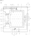
FIG. 1 is a diagram illustrating an example of a laundry treating apparatus. -
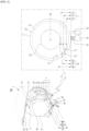
FIG. 2 is a diagram illustrating an example of a capacitive sensor provided in a laundry treating apparatus. -
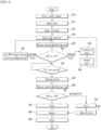
FIG. 3 andFIG. 4 are diagrams illustrating an example of a method of controlling a laundry treating apparatus. - Hereinafter, a preferred embodiment of an apparatus for treating laundry and method of controlling the same will be described in detail with reference to the accompanying drawings.
- As shown in
FIG. 1 , alaundry treating apparatus 100 includes acabinet 1, atub 2 provided inside the cabinet to provide a space for storing water, and adrum 3 rotatably provided inside the tub to store laundry. - The
cabinet 1 is provided to include afront panel 11 forming a front surface of the laundry treating apparatus, and thefront panel 11 is provided with an entrance 12 allowing the inside of the cabinet to communicate with the outside. The entrance 12 may be provided to be opened and closed by a door 13 rotatably provided on thefront panel 11. - The
front panel 11 may be provided with acontrol panel 14. And, thecontrol panel 14 may include a display unit displaying information of a user-selectable course and the like, a power switch supplying power to the laundry treating apparatus, and an input unit enabling selection and execution of a control command displayed on the display unit. - The
tub 2 may be provided as acylindrical tub body 21 of which inside is hollow. Atub entrance 23 is provided at any one of a front surface 22 (i.e., a tub front surface) and a rear surface 26 (i.e., a tub rear surface) of thetub body 21. The diagram illustrates a case in which atub entrance 23 is provided at thetub front surface 22. - The
tub entrance 23 is connected to the entrance 12 through aninsulating part 24. Theinsulating part 24 may be made of an elastic body (e.g., rubber, etc.) and may be provided as a pipe-shaped insulating body connecting the entrance 12 and thetub entrance 23. The insulatingpart 24 is a means for preventing the water stored in thetub body 21 from being discharged to thecabinet 1 through thetub entrance 23, and for attenuating the transmission of the vibration of thetub body 21 to thecabinet 1. - The
tub body 21 may be fixed to the inside of thecabinet 1 through atub support part 25. Thetub support part 25 may include a spring for fixing a region of a circumferential surface of thetub body 21 that is located above a horizontal line that passes through a rotation center of the drum to thecabinet 1 and a damper for fixing a region of the circumferential surface of thetub body 21 that is located below the horizontal line that passes through the rotation center of the drum to a bottom surface of the cabinet. - The
drum 3 is provided to include adrum body 31 rotatable inside thetub body 21. Thedrum body 31 is provided in a cylindrical shape with an empty inside, and a drum through-hole 311 allowing the inside of the drum body to communicate with the inside of the tub body is provided on a circumferential surface, a front surface, a rear surface, and the like of thedrum body 31. In addition, adrum entrance 32 is provided to a surface (i.e., a front surface of the drum) facing theentrance 11 in a space provided by thedrum body 31. - The
drum body 31 is rotated by thedriving unit 33, which includes astator 331 fixed to a rear surface of thetub body 21 to generate a rotating field, arotor 332 located outside thetub body 21 to be rotated by the rotating field, and a rotatingshaft 333 passing through the rear surface of thetub body 31 to connect the rear surface of thedrum body 31 and therotor 332. - The
laundry treating apparatus 100 supplies water to thetub body 21 through the water supply unit 4, and the water stored in thetub body 21 is discharged to the outside of thecabinet 1 through thedrain unit 6. - The water supply unit 4 may include a
water supply pipe 41 connecting thetub body 21 with a water supply source (not shown) and awater supply valve 43 controlling the opening and closing of thewater supply pipe 41. - The
drain unit 6 may include adrain pump 63, afirst drain pipe 61 for guiding the water of thetub body 21 to thedrain pump 63, and asecond drain pipe 63 for guiding the water discharged from thedrain pump 63 to the outside of thecabinet 1. - The
laundry treating apparatus 100 is provided to include adetergent supply unit 5 for supplying detergent to thetub body 21. - The
detergent supply unit 5 may be provided to supply detergent to thetub body 21 when water is supplied to the tub through thewater supply pipe 41, or may be provided to supply detergent independently of whether thewater supply pipe 41 is opened.FIG. 1 illustrates an example of the former case. - The
detergent supply unit 5 ofFIG. 1 may include astorage body 51 that provides a space where detergent is stored and ahousing 52 that is provided inside thecabinet 1 to provide a space where thestorage body 51 is accommodated. - A
discharge passage 511 is provided inside thestorage body 51, anozzle 53 for supplying water supplied from thewater supply pipe 41 to thestorage body 51 is provided to an upper surface of thestorage body 51, and thehousing 52 is connected to thetub body 21 through asupply pipe 54. Therefore, when water is supplied to thestorage body 51 through thenozzle 53, water and detergent inside thestorage body 51 are discharged to thehousing 52 through thedischarge passage 511, and the water and detergent inside thehousing 52 may move to thetub body 21 through thesupply pipe 54. - As shown in
FIG. 2 , thelaundry treating apparatus 100 is provided to include a sensor 7 (e.g., a capacitive sensor or an electrostatic sensor) capable of detecting at least one of an amount of foam (such as the height of foam) generated inside thetub body 21 and the height of water stored in thetub body 21 by detecting the change in capacitance inside thetub body 21. The sensor 7 is fixed to the circumferential surface, thefront surface 22, and the rear surface 26 of thetub body 21 and is located in an outer space (e.g., a space where water is not stored) of thetub body 21. - The sensor 7 may be provided as a capacitive sensor that includes two electrodes spaced apart from each other to output different signals according to changes in capacitance of a material located between the two electrodes (e.g., depending on a change in a dielectric constant of the material located between the two electrodes).
- The sensor 7 may be fixed to any one of the circumferential surface, the
front surface 22, and the rear surface 26 of thetub body 21, but considering that the water inside thetub body 21 may move along the circumferential surface of the tub body during high-speed rotation of thedrum 3, it is preferable to be fixed to at least one of thefront surface 22 and the rear surface 26 of the tub. The aforementioned sensor 7 may detect an amount of foam or a water level through a change in capacitance detected when foam or water rises to a point where the sensor is located, which is because it will be difficult to implement the aforementioned function in a situation where water moves along the circumferential surface of thetub body 21. - As shown in
FIG. 1 , when a central axis S1 of thetub body 21 is provided as a cylinder parallel to the ground, the sensor 7 may be fixed to at least one of thefront surface 22 of the tub and the rear surface 26 of the tub.FIG. 2 illustrates a case where the sensor 7 is fixed to thefront surface 22 of the tub as an example. - Unlike the drawing, when the central axis S1 of the
tub body 21 is provided as a cylinder inclined at an angle of less than 90 degrees with respect to the ground (in this case, the tub entrance is provided on a front side of the cylinder), it is preferable that the sensor 7 is fixed to the front side of the tub that is less affected by water stored inside the tub body. - Furthermore, if the central axis S1 of the
tub body 21 is provided as a cylinder orthogonal to the ground (in this case, the tub entrance is provided on an upper surface of the tub body), the sensor 7 may be fixed to the upper surface of thetub body 21 or may be fixed to an area of the circumferential surface of thetub body 21 located above the horizontal line passing through the center of the tub body. - When the sensor 7 is provided to sense a height of foam, the sensor 7 may be fixed at a position capable of determining whether the foam inside the
tub body 21 has reached a preset reference height H. The reference height H may be set to a height of the foam in which a rotational speed of thedrum 3 is lower by 10% or more than a preset speed when power of a preset reference power amount is supplied to the drivingunit 33. - The reference height is set to a single value, and the sensor 7 may be provided as a single capacitive sensor located at the reference height.
- Alternatively, the reference height H is set to a multitude of heights H1, H2, and H3 corresponding to a multitude of reference levels L set to increase in proportion to an amount of laundry put into the
drum 3, and the number of the sensor(s) 7 provided may be the same as the number of the reference height(s) H. - That is, the reference water level L may include a lowest water level L1 at which a lowest point in the circumferential surface of the
drum body 21 is submerged, a highest water level L3 set higher than the lowest water level, and an intermediate water level L2 positioned between the lowest water level and the highest water level. The highest water level L3 may be set to a lower water level than a horizontal line S2 passing through the center of thetub entrance 23. - In this case, the reference height H may include a first reference height H1 between the lowest water level L1 and the intermediate water level L2, a second reference height H2 between the intermediate water level L2 and the highest water level L3, and a third reference height H3 above the highest water level L3. The sensor 7 may include a
first sensor 71 fixed to thefront surface 22 of the tub and located at the first reference height H1, asecond sensor 72 located at the second reference height H2, and athird sensor 73 located at the third reference height H3. - Unlike the drawing, the reference level L may be set to the lowest water level L1 and the intermediate water level L2, the reference height H may be set to the first reference height H1 and the second reference height H2, and the sensor 7 may be provided to include only the
first sensor 71 located at the first reference height and thesecond sensor 72 located at the second reference height. - In addition, the reference water level L may be set to the lowest water level L1 and the highest water level L3, the reference height H may be set to the first reference height H1 and the third reference height H3, and the sensor 7 may be provided to include only the
first sensor 71 located at the first reference height and thethird sensor 73 located at the third reference height. - Unlike the drawing, the sensor 7 may be provided to determine whether the water level inside the
tub body 21 has reached the reference water level L. - As described above, the reference water level L may be set to include a lowest water level L1 set to a water level at which a lowest point of the circumferential surface of the
drum body 31 is submerged, a highest water level L3 located at a point higher than the lowest water level and lower than the horizontal line S2 passing through the center of thetub entrance 23, and an intermediate water level L2 positioned between the lowest water level and the highest water level. - In this case, it is preferable that the
first sensor 71 is fixed to thefront surface 22 of the tub to be located at the same height as the lowest water level L1, thesecond sensor 72 is fixed to be located at the same height as the intermediate water level L2, and thethird sensor 73 is fixed to be located at the same height as the highest water level L3. - Unlike the above description, the reference water level L is set to the lowest water level L1 and the intermediate water level L2, and the sensor 7 may include only the
first sensor 71 for detecting the lowest water level L1 and thesecond sensor 72 for detecting the intermediate water level L2. - In addition, the reference water level L is set to the lowest water level L1 and the highest water level L3, and the sensor 7 may include only the
first sensor 71 for detecting the lowest water level L1 and thethird sensor 73 for detecting the highest water level L3. - Accordingly, the
laundry treating apparatus 100 may accurately measure the water level inside thetub body 21, whether foam has been generated, or a height of the foam inside thetub body 21 in real time through the sensor 7. -
FIG. 3 illustrates an example of the above-described method of controlling the laundry treating apparatus. For convenience, the description will be made based on a case where there is only one sensor 7. - The control method includes a laundry amount detecting step S10 of determining an amount of laundry stored in the
tub 3 by rotating the drum 3 (S10), a water supply step S21 of supplying water thetub 2 through the water supply unit 4, a detergent supply step S22 of supplying detergent to thetub 2 by thedetergent supply unit 5, a washing step S30 of removing foreign substances from the laundry by rotating thedrum 3, and a measuring step (a first measuring step) S40 of measuring by the sensor 7 whether capacitance inside thetub body 21 has increased and a time for which the capacitance has continued to increase during the washing step S30. - The water supply step S21 and the detergent supply step S22 may be performed independently of each other, or the detergent supply step S22 may be configured to be executed by the water supply step S21.
- The washing step S30 may be provided to alternately perform clockwise rotation and counterclockwise rotation of the drum. The measuring step S40 may be continuously performed while the washing step S30 is performed, or may be provided to be periodically executed while the washing step S30 is performed.
- When a capacitance inside the
tub body 21 is greater than or equal to a reference capacitance h (e.g., a height of foam inside the tub body reaches a reference height H) and a state in which the capacitance is greater than or equal to the reference capacitance continues over a first reference time T1, the control method may execute a changing step S42 of changing at least one of a rotational speed and a rotation direction of the drum set in the washing step S30. - The state in which the capacitance inside the
tub body 21 is greater than or equal to the reference capacitance means that the height h of the foam inside thetub body 21 reaches the reference height H. Accordingly, the changing step S42 is started when the state in which the height h of the foam inside thetub body 21 is greater than or equal to the reference height H continues over the first reference time T1. - Since the changing step S42 is a means to suppress the further generation of foam as much as possible, the changing step S42 is preferably provided to lower a rotational speed of the drum or to change a rotational direction change period of the drum to be long.
- On the other hand, if the capacitance inside the
tub body 21 is greater than or equal to the reference capacitance and the state in which the capacitance is greater than or equal to the reference capacitance is continued for more than or equal to a second reference time T2 longer than the first reference time T1, the control method may be provided to execute an intermediate drain step S43 of draining the water stored in thetub 2 and a water resupply step S44 of supplying water to thetub 2 after completion of the intermediate drain step. - The intermediate drain step S43 is performed through the
drain unit 6, and the water resupply step S44 is performed through the water supply unit 4. The intermediate drain step S43 and the water resupply step S44 may be performed after temporarily stopping the washing step S30. - If it is determined that the foam inside the
tub body 21 is less than a predetermined amount, the control method executes the washing step S30 and the measuring step S40 until a preset time elapses. - That is, if the capacitance measured in the measuring step S40 is less than the reference capacitance (or the foam inside the tub body does not reach the reference height), or if a duration time T of such a state is less than the first reference time T1 despite that the capacitance is equal to or greater than the reference capacitance, the control method determines whether the time for performing the washing step S30 has reached the set time (S45).
- If it is determined that the washing step S30 has been executed for the set time (S45), the control method proceeds to an observation motion executing step S50. The observation motion executing step S50 is a step of executing an observation motion (e.g., a tumbling motion) in which the
drum 3 is rotated at a rotational speed at which a centrifugal force of less than 1 G is induced only in one of a clockwise direction and a counterclockwise direction. - During the observation motion executing step S50, the control method executes a measuring step (i.e., a second measuring step) S60, in which the sensor 7 measures whether the capacitance inside the
tub body 21 increases and the time the capacitance continued to increase. - If the capacitance measured during the observation motion executing step S50 is less than the reference capacitance or if the duration T of such a state is less than a preset third reference time T3 despite that the capacitance is equal to or greater than the reference capacitance (S61), the control method may sequentially execute a draining step S70, a dewatering step S80, and a rinsing step S90.
- The draining step S70 may be provided to discharge the water stored in the
tub 2 to the outside of the cabinet, and the dewatering step S80 may be provided to remove water from laundry by rotating thedrum 3 at a rotational speed at which a centrifugal force of 1G or more is induced. - The rinsing step S90 may be provided to separate detergent and foreign substances from laundry through a process of supplying water to the
tub 2 and rotating thedrum 3 at a rotational speed that induces a centrifugal force of less than 1G after completion of the dewatering step S80. - Meanwhile, when the capacitance measured during the progress of the observation motion executing step S50 is greater than or equal to the reference capacitance and the time T for which the capacitance continues to be greater than or equal to the reference capacitance is greater than or equal to the third reference time T3, the control method may be provided to execute only the draining step S62 and the rinsing step S90.
- When a large amount of foam is detected in the observation motion executing step S50, it may be difficult to increase the rotational speed of the drum to a preset dewatering speed during the proceeding of the dewatering step S80. This is because the foam inside the
tub 2 acts as a load of the drivingunit 33. When a large amount of foam is detected in the observation motion executing step S50, an error is highly likely to occur when the dewatering step S80 is executed, and thus the control method may execute only the draining step S62 and the rinsing step S90 while omitting the dewatering step S80. -
FIG. 4 illustrates another embodiment of a method of controlling a laundry treating apparatus. In the control method of the present embodiment, the steps S70, S80, and S90, which are executed when the capacitance measured in the process of the observation motion executing step S50 and the second measuring step S60 or during the progress of the observation motion executing step S50 is less than the reference capacitance or when the duration time T of the state in which the capacitance is equal to or greater than the reference capacitance is less than the third reference time, are the same as those of the embodiment ofFIG. 3 . - If the capacitance measured by the sensor 7 during the progress of the observation motion executing step S50 is greater than or equal to the reference capacitance and the duration time T of the state in which the capacitance is greater than or equal to the reference capacitance is greater than or equal to the third reference time T3, the control method is characterized in that the draining step S62, the foam removing step S63, the dewatering step S80, and the rinsing step S90 are sequentially executed.
- The draining step S62, the dewatering step S80, and the rinsing step S90 may be provided in the same manner as the draining step, the dewatering step, and the rinsing step provided in the control method of
FIG. 3 . - The foam removing step S63 may be provided as a step of simultaneously executing a process in which the water supply unit 4 supplies water to the
tub 2 and a process in which thedrain unit 6 drains the water supplied to thetub 2. - When water supply and drainage are simultaneously performed through the foam removing step S63, the foam inside the tub may be discharged to the outside of the tub, so the control method according to the present embodiment may reduce the possibility of an error occurring due to the foam when executing the dewatering step S80.
- Since the above-described structure and control method of the laundry treating apparatus relate to an example of the present application, the scope of the rights of the present application may not be limited to the above-described structure and control method.
Claims (17)
- An apparatus for treating laundry, the apparatus comprising:a tub having a tub body providing a space for storing water and a tub entrance perforating one surface of the tub body;a drum having a drum body rotatably provided within the tub to store the laundry and a drum entrance perforating one surface of the drum body to communicate with the tub entrance;a water supply unit supplying water to the tub;a detergent supply unit supplying detergent to the tub; anda sensor detecting a change in capacitance inside the tub body to sense at least one of a height of foam generated within the tub body or a height of the water stored in the tub body.
- The apparatus of claim 1, wherein the tub body is provided as a cylinder in a hollow shape having a central axis parallel to a ground, wherein the tub entrance is provided in any one of a front surface or a rear surface of the cylinder, and wherein the sensor is fixed to at least one of the front surface or the rear surface.
- The apparatus of claim 1, wherein the tub body is provided as a cylinder in a hollow shape having a central axis orthogonal to a ground, wherein the tub entrance is provided in an upper surface of the cylinder, and wherein the sensor is fixed to at least one of the upper surface and an area in a circumferential surface of the tub body located above a horizontal line passing through a center of the tub body.
- The apparatus of claim 1, wherein the tub body is provided as a cylinder in a hollow shape having a central axis inclined at an angle of less than 90 degrees with respect to a ground, wherein the tub entrance is provided in a front surface of the cylinder, and wherein the sensor is fixed to the front surface.
- The apparatus of claim 2, wherein the sensor is fixed at a position capable of determining whether the foam within the tub body has reached a preset reference height.
- The apparatus of claim 5, further comprising a driving unit providing a motive power necessary for rotation of the drum, wherein the reference height is set to a height of the foam at which a rotational speed of the drum becomes lower than a set speed by 10% or more when a power of a preset reference power amount is supplied to the driving unit.
- The apparatus of claim 5, wherein the reference height is set to a multitude of heights corresponding to a multitude of reference water levels set to increase in proportion to an amount of the laundry put into the drum and wherein the number of the sensors is equal to the number of the reference heights.
- The apparatus of claim 7, wherein the reference water level comprises a lowest water level set to a water level at which a lowest point of a circumferential surface of the drum body is submerged, a highest water level located at a point higher than the lowest water level and lower than a horizontal line passing through a center of the tub entrance, and an intermediate water level located between the lowest water level and the highest water level,wherein the reference height comprises a first reference height positioned between the lowest water level and the intermediate water level, a second reference height positioned between the intermediate water level and the highest water level, and a third reference height positioned at a point higher than the highest water level, andwherein the sensor comprises a first sensor fixed to the front surface and positioned at the first reference height, a second sensor positioned at the second reference height, and a third sensor positioned at the third reference height.
- The apparatus of claim 2, wherein the sensor is fixed at a position capable of determining whether a water level inside the tub body reaches a reference water level.
- The apparatus of claim 9, wherein the reference water level comprises a lowest water level set to a water level at which a lowest point of a circumferential surface of the drum body is submerged, a highest water level located at a point higher than the lowest water level and lower than a horizontal line passing through a center of the tub entrance, and an intermediate water level located between the lowest water level and the highest water level and
wherein the sensor comprises a first sensor positioned at the same height as the lowest water level, a second sensor positioned at the same height as the intermediate water level, and a third sensor positioned at the same height as the highest water level. - A method of controlling a laundry treating apparatus comprising a tub providing a space for storing water, a drum rotatably provided in the tub to store laundry, a water supply unit supplying water to the tub, a detergent supply unit supplying detergent to the tub, and a sensor detecting a change in capacitance inside a tub body to sense at least one of a height of foam generated inside the tub body or a height of water stored in the tub body, the method comprising:a laundry amount detecting step of determine an amount of the laundry stored in the drum by rotating the drum;a water supply step of supplying the water to the tub through a water supply unit according to a laundry amount;a detergent supply step of supplying the detergent to the tub by the detergent supply unit;a washing step of removing foreign substances from the laundry by rotating the drum; anda measuring step of measuring by the sensor whether capacitance inside the tub body has increased and a time for which the capacitance has continued to increase during the washing step.
- The method of claim 11, wherein when the capacitance inside the tub body is equal to or greater than a reference capacitance (e.g., when the foam inside the tub body reaches a reference height) and a state in which the capacitance is greater than or equal to the reference capacitance continues for a first reference time or more, the washing step decreases a rotational speed of the drum.
- The method of claim 11, wherein the washing step is configured to alternately execute clockwise rotation and counterclockwise rotation of the drum and
wherein when the capacitance inside the tub body is equal to or greater than a reference capacitance and a state in which the capacitance is equal to or greater than the reference capacitance continues for a first reference time or more, the washing step sets a rotation direction change period of the drum to be long. - The method of claim 11, further comprising:an intermediate drain step of draining the water stored in the tub when the capacitance inside the tub body is equal to or greater than a reference capacitance and a state in which the capacitance is greater than or equal to the reference capacitance continues for more than a second reference time longer than the first reference time; anda water resupply step of supplying water to the tub after completion of the intermediate drain step.
- The method of claim 11, further comprising:an observation motion executing step of rotating the drum at a rotational speed of inducing a centrifugal force less than 1G in either a clockwise direction or a counterclockwise direction, the observation motion executing step executed in progress of the washing step ;a draining step of draining the water stored in the tub when the capacitance measured by the sensor in progress of the observation motion executing step is less than a reference capacitance or a holding time of a state in which the capacitance is equal to or greater than the reference capacitance is less than a preset third reference time;a dewatering step of removing water from the laundry by rotating the drum at a rotational speed of inducing a centrifugal force equal to or greater than 1G; anda rinsing step of separating the detergent and foreign substances from the laundry by rotating the drum at a rotational speed of inducing the centrifugal force less than 1G after supplying water to the tub after completion of the dewatering step.
- The method of claim 15, further comprising:a draining step of draining the water stored in the tub when the capacitance measured by the sensor in progress of the observation motion executing step is equal to or greater than the reference capacitance and a holding time of a state in which the capacitance is greater than or equal to the reference capacitance is greater than or equal to the third reference time; anda rinsing step of separating the detergent and foreign substances from the laundry by rotating the drum after supplying water to the tub.
- The method of claim 15, further comprising:a draining step of draining the water stored in the tub when the capacitance measured by the sensor in progress of the observation motion executing step is equal to or greater than the reference capacitance and a holding time of a state in which the capacitance is greater than or equal to the reference capacitance is greater than or equal to the third reference time;a foam removing step of simultaneously executing a process of supplying the water to the tub by the water supply unit and a process of draining the water supplied to the tub by a drain unit; anda dewatering step of removing water from the laundry by rotating the drum at a rotational speed of inducing the centrifugal force equal to or greater 1G based on completing the foam removing step.
Applications Claiming Priority (2)
| Application Number | Priority Date | Filing Date | Title |
|---|---|---|---|
| KR1020220012212A KR20230115581A (en) | 2022-01-27 | 2022-01-27 | Laundry Treatment Apparatus and Control Method for the same |
| PCT/KR2022/018290 WO2023146086A1 (en) | 2022-01-27 | 2022-11-18 | Clothing processing apparatus and method for controlling clothing processing apparatus |
Publications (2)
| Publication Number | Publication Date |
|---|---|
| EP4467703A1 true EP4467703A1 (en) | 2024-11-27 |
| EP4467703A4 EP4467703A4 (en) | 2025-04-23 |
Family
ID=87472259
Family Applications (1)
| Application Number | Title | Priority Date | Filing Date |
|---|---|---|---|
| EP22924339.9A Pending EP4467703A4 (en) | 2022-01-27 | 2022-11-18 | Clothing processing apparatus and method for controlling clothing processing apparatus |
Country Status (4)
| Country | Link |
|---|---|
| US (1) | US20250146208A1 (en) |
| EP (1) | EP4467703A4 (en) |
| KR (1) | KR20230115581A (en) |
| WO (1) | WO2023146086A1 (en) |
Family Cites Families (16)
| Publication number | Priority date | Publication date | Assignee | Title |
|---|---|---|---|---|
| US2875526A (en) * | 1955-12-01 | 1959-03-03 | Murray Corp | Combined washer and drier |
| JPH07185183A (en) * | 1993-12-28 | 1995-07-25 | Matsushita Electric Ind Co Ltd | Washing machine |
| KR100282343B1 (en) | 1998-10-12 | 2001-02-15 | 구자홍 | Foam detection method of drum washing machine |
| KR101095555B1 (en) | 2005-05-04 | 2011-12-19 | 삼성전자주식회사 | Washing machine and its foaming method |
| US20080155760A1 (en) * | 2006-12-28 | 2008-07-03 | General Electric Company | Method and apparatus for operating a washing machine |
| DE102007036041A1 (en) * | 2007-08-01 | 2009-02-05 | BSH Bosch und Siemens Hausgeräte GmbH | Method for removing foam in a drum washing machine and drum washing machine suitable for this purpose |
| KR101448624B1 (en) * | 2007-12-31 | 2014-10-08 | 엘지전자 주식회사 | Control method of washing machine |
| JP5598283B2 (en) * | 2010-11-24 | 2014-10-01 | パナソニック株式会社 | Drum washing machine |
| KR102244263B1 (en) * | 2014-03-07 | 2021-04-27 | 삼성전자주식회사 | Washing machine and control method thereof |
| KR102439141B1 (en) * | 2015-04-01 | 2022-09-02 | 삼성전자주식회사 | Washing machine and washing machine control method |
| US10047469B2 (en) * | 2015-12-21 | 2018-08-14 | Whirlpool Corporation | Laundry treating appliance with over-sudsing condition compensation measures |
| CN106968080A (en) * | 2016-01-14 | 2017-07-21 | 青岛海尔滚筒洗衣机有限公司 | A kind of method that clothes washing is carried out using steam |
| KR20170138882A (en) * | 2016-06-08 | 2017-12-18 | 엘지전자 주식회사 | Laundry Treating Apparatus and Control Method thereof |
| DE102018004188B4 (en) * | 2018-05-24 | 2019-12-05 | Diehl Ako Stiftung & Co. Kg | Laundry treatment device |
| KR102694109B1 (en) * | 2019-02-01 | 2024-08-12 | 엘지전자 주식회사 | sensor module and clothes treatment apparatus having the same |
| KR20210050779A (en) * | 2019-10-29 | 2021-05-10 | 엘지전자 주식회사 | A Control Method of Laundry Treatment Apparatus |
-
2022
- 2022-01-27 KR KR1020220012212A patent/KR20230115581A/en active Pending
- 2022-11-18 US US18/833,020 patent/US20250146208A1/en active Pending
- 2022-11-18 WO PCT/KR2022/018290 patent/WO2023146086A1/en not_active Ceased
- 2022-11-18 EP EP22924339.9A patent/EP4467703A4/en active Pending
Also Published As
| Publication number | Publication date |
|---|---|
| US20250146208A1 (en) | 2025-05-08 |
| KR20230115581A (en) | 2023-08-03 |
| WO2023146086A1 (en) | 2023-08-03 |
| EP4467703A4 (en) | 2025-04-23 |
Similar Documents
| Publication | Publication Date | Title |
|---|---|---|
| KR101287536B1 (en) | Washing machine and its control method | |
| US10066333B2 (en) | Washing machine with ball balancer and method of controlling vibration reduction thereof | |
| EP3290561A1 (en) | Washing machine and method of controlling the same | |
| RU2619011C2 (en) | Washing machine and control thereof | |
| KR102491974B1 (en) | washing machine and controlling method of washing machine | |
| US11926948B2 (en) | Control method of the laundry apparatus | |
| KR20160094723A (en) | Method for controlling process in washing machine | |
| US11208748B2 (en) | Method of controlling washing machine | |
| KR101156713B1 (en) | Drum Washing machine and control method thereof | |
| KR20100040172A (en) | Washing machine and spin control method thereof | |
| KR20220056146A (en) | Laundry Treatment Apparatus | |
| EP4467703A1 (en) | Clothing processing apparatus and method for controlling clothing processing apparatus | |
| JP2020081404A (en) | Dehydrator | |
| EP3650596B1 (en) | Washing machine | |
| KR20180089965A (en) | Control Method for Laundry Treating Apparatus | |
| KR100207025B1 (en) | Washing machine control method | |
| JP7765170B2 (en) | washing machine | |
| KR20210097458A (en) | Laundry Treatment Apparatus and Control Method for the same | |
| KR20220056145A (en) | Laundry Treatment Apparatus | |
| KR20210097457A (en) | Laundry Treatment Apparatus and Contol Method for the same | |
| KR20210097456A (en) | Laundry Treatment Apparatus and Control Method for the same | |
| KR20180089966A (en) | Laundry Treating Apparatus and Control Method for the same | |
| JP4510789B2 (en) | Drum washing machine | |
| CN119032205A (en) | Clothes treatment device | |
| KR100751795B1 (en) | How to detect unbalance in washing machine |
Legal Events
| Date | Code | Title | Description |
|---|---|---|---|
| STAA | Information on the status of an ep patent application or granted ep patent |
Free format text: STATUS: THE INTERNATIONAL PUBLICATION HAS BEEN MADE |
|
| PUAI | Public reference made under article 153(3) epc to a published international application that has entered the european phase |
Free format text: ORIGINAL CODE: 0009012 |
|
| STAA | Information on the status of an ep patent application or granted ep patent |
Free format text: STATUS: REQUEST FOR EXAMINATION WAS MADE |
|
| 17P | Request for examination filed |
Effective date: 20240823 |
|
| AK | Designated contracting states |
Kind code of ref document: A1 Designated state(s): AL AT BE BG CH CY CZ DE DK EE ES FI FR GB GR HR HU IE IS IT LI LT LU LV MC ME MK MT NL NO PL PT RO RS SE SI SK SM TR |
|
| REG | Reference to a national code |
Ref country code: DE Ref legal event code: R079 Free format text: PREVIOUS MAIN CLASS: D06F0034140000 Ipc: D06F0033470000 |
|
| A4 | Supplementary search report drawn up and despatched |
Effective date: 20250320 |
|
| RIC1 | Information provided on ipc code assigned before grant |
Ipc: D06F 105/52 20200101ALN20250314BHEP Ipc: D06F 105/08 20200101ALN20250314BHEP Ipc: D06F 105/02 20200101ALN20250314BHEP Ipc: D06F 103/18 20200101ALN20250314BHEP Ipc: D06F 37/04 20060101ALN20250314BHEP Ipc: D06F 33/42 20200101ALN20250314BHEP Ipc: D06F 33/38 20200101ALN20250314BHEP Ipc: D06F 33/34 20200101ALN20250314BHEP Ipc: D06F 39/08 20060101ALI20250314BHEP Ipc: D06F 39/06 20060101ALI20250314BHEP Ipc: D06F 34/14 20200101ALI20250314BHEP Ipc: D06F 33/47 20200101AFI20250314BHEP |
|
| DAV | Request for validation of the european patent (deleted) | ||
| DAX | Request for extension of the european patent (deleted) |