EP4467699A1 - Commingled fiber preform architecture for high temperature composites - Google Patents
Commingled fiber preform architecture for high temperature composites Download PDFInfo
- Publication number
- EP4467699A1 EP4467699A1 EP24177165.8A EP24177165A EP4467699A1 EP 4467699 A1 EP4467699 A1 EP 4467699A1 EP 24177165 A EP24177165 A EP 24177165A EP 4467699 A1 EP4467699 A1 EP 4467699A1
- Authority
- EP
- European Patent Office
- Prior art keywords
- fibers
- commingled
- fugitive
- percentage
- fusible
- Prior art date
- Legal status (The legal status is an assumption and is not a legal conclusion. Google has not performed a legal analysis and makes no representation as to the accuracy of the status listed.)
- Pending
Links
Images






Classifications
-
- B—PERFORMING OPERATIONS; TRANSPORTING
- B32—LAYERED PRODUCTS
- B32B—LAYERED PRODUCTS, i.e. PRODUCTS BUILT-UP OF STRATA OF FLAT OR NON-FLAT, e.g. CELLULAR OR HONEYCOMB, FORM
- B32B5/00—Layered products characterised by the non- homogeneity or physical structure, i.e. comprising a fibrous, filamentary, particulate or foam layer; Layered products characterised by having a layer differing constitutionally or physically in different parts
- B32B5/02—Layered products characterised by the non- homogeneity or physical structure, i.e. comprising a fibrous, filamentary, particulate or foam layer; Layered products characterised by having a layer differing constitutionally or physically in different parts characterised by structural features of a fibrous or filamentary layer
- B32B5/12—Layered products characterised by the non- homogeneity or physical structure, i.e. comprising a fibrous, filamentary, particulate or foam layer; Layered products characterised by having a layer differing constitutionally or physically in different parts characterised by structural features of a fibrous or filamentary layer characterised by the relative arrangement of fibres or filaments of different layers, e.g. the fibres or filaments being parallel or perpendicular to each other
-
- D—TEXTILES; PAPER
- D04—BRAIDING; LACE-MAKING; KNITTING; TRIMMINGS; NON-WOVEN FABRICS
- D04B—KNITTING
- D04B21/00—Warp knitting processes for the production of fabrics or articles not dependent on the use of particular machines; Fabrics or articles defined by such processes
- D04B21/14—Fabrics characterised by the incorporation by knitting, in one or more thread, fleece, or fabric layers, of reinforcing, binding, or decorative threads; Fabrics incorporating small auxiliary elements, e.g. for decorative purposes
- D04B21/16—Fabrics characterised by the incorporation by knitting, in one or more thread, fleece, or fabric layers, of reinforcing, binding, or decorative threads; Fabrics incorporating small auxiliary elements, e.g. for decorative purposes incorporating synthetic threads
- D04B21/165—Fabrics characterised by the incorporation by knitting, in one or more thread, fleece, or fabric layers, of reinforcing, binding, or decorative threads; Fabrics incorporating small auxiliary elements, e.g. for decorative purposes incorporating synthetic threads with yarns stitched through one or more layers or tows, e.g. stitch-bonded fabrics
-
- B—PERFORMING OPERATIONS; TRANSPORTING
- B29—WORKING OF PLASTICS; WORKING OF SUBSTANCES IN A PLASTIC STATE IN GENERAL
- B29B—PREPARATION OR PRETREATMENT OF THE MATERIAL TO BE SHAPED; MAKING GRANULES OR PREFORMS; RECOVERY OF PLASTICS OR OTHER CONSTITUENTS OF WASTE MATERIAL CONTAINING PLASTICS
- B29B11/00—Making preforms
- B29B11/14—Making preforms characterised by structure or composition
- B29B11/16—Making preforms characterised by structure or composition comprising fillers or reinforcement
-
- B—PERFORMING OPERATIONS; TRANSPORTING
- B32—LAYERED PRODUCTS
- B32B—LAYERED PRODUCTS, i.e. PRODUCTS BUILT-UP OF STRATA OF FLAT OR NON-FLAT, e.g. CELLULAR OR HONEYCOMB, FORM
- B32B37/00—Methods or apparatus for laminating, e.g. by curing or by ultrasonic bonding
- B32B37/14—Methods or apparatus for laminating, e.g. by curing or by ultrasonic bonding characterised by the properties of the layers
- B32B37/16—Methods or apparatus for laminating, e.g. by curing or by ultrasonic bonding characterised by the properties of the layers with all layers existing as coherent layers before laminating
-
- B—PERFORMING OPERATIONS; TRANSPORTING
- B32—LAYERED PRODUCTS
- B32B—LAYERED PRODUCTS, i.e. PRODUCTS BUILT-UP OF STRATA OF FLAT OR NON-FLAT, e.g. CELLULAR OR HONEYCOMB, FORM
- B32B38/00—Ancillary operations in connection with laminating processes
- B32B38/0036—Heat treatment
-
- B—PERFORMING OPERATIONS; TRANSPORTING
- B32—LAYERED PRODUCTS
- B32B—LAYERED PRODUCTS, i.e. PRODUCTS BUILT-UP OF STRATA OF FLAT OR NON-FLAT, e.g. CELLULAR OR HONEYCOMB, FORM
- B32B5/00—Layered products characterised by the non- homogeneity or physical structure, i.e. comprising a fibrous, filamentary, particulate or foam layer; Layered products characterised by having a layer differing constitutionally or physically in different parts
- B32B5/02—Layered products characterised by the non- homogeneity or physical structure, i.e. comprising a fibrous, filamentary, particulate or foam layer; Layered products characterised by having a layer differing constitutionally or physically in different parts characterised by structural features of a fibrous or filamentary layer
- B32B5/022—Non-woven fabric
-
- B—PERFORMING OPERATIONS; TRANSPORTING
- B32—LAYERED PRODUCTS
- B32B—LAYERED PRODUCTS, i.e. PRODUCTS BUILT-UP OF STRATA OF FLAT OR NON-FLAT, e.g. CELLULAR OR HONEYCOMB, FORM
- B32B5/00—Layered products characterised by the non- homogeneity or physical structure, i.e. comprising a fibrous, filamentary, particulate or foam layer; Layered products characterised by having a layer differing constitutionally or physically in different parts
- B32B5/02—Layered products characterised by the non- homogeneity or physical structure, i.e. comprising a fibrous, filamentary, particulate or foam layer; Layered products characterised by having a layer differing constitutionally or physically in different parts characterised by structural features of a fibrous or filamentary layer
- B32B5/024—Woven fabric
-
- B—PERFORMING OPERATIONS; TRANSPORTING
- B32—LAYERED PRODUCTS
- B32B—LAYERED PRODUCTS, i.e. PRODUCTS BUILT-UP OF STRATA OF FLAT OR NON-FLAT, e.g. CELLULAR OR HONEYCOMB, FORM
- B32B5/00—Layered products characterised by the non- homogeneity or physical structure, i.e. comprising a fibrous, filamentary, particulate or foam layer; Layered products characterised by having a layer differing constitutionally or physically in different parts
- B32B5/02—Layered products characterised by the non- homogeneity or physical structure, i.e. comprising a fibrous, filamentary, particulate or foam layer; Layered products characterised by having a layer differing constitutionally or physically in different parts characterised by structural features of a fibrous or filamentary layer
- B32B5/08—Layered products characterised by the non- homogeneity or physical structure, i.e. comprising a fibrous, filamentary, particulate or foam layer; Layered products characterised by having a layer differing constitutionally or physically in different parts characterised by structural features of a fibrous or filamentary layer the fibres or filaments of a layer being of different substances, e.g. conjugate fibres, mixture of different fibres
-
- B—PERFORMING OPERATIONS; TRANSPORTING
- B32—LAYERED PRODUCTS
- B32B—LAYERED PRODUCTS, i.e. PRODUCTS BUILT-UP OF STRATA OF FLAT OR NON-FLAT, e.g. CELLULAR OR HONEYCOMB, FORM
- B32B5/00—Layered products characterised by the non- homogeneity or physical structure, i.e. comprising a fibrous, filamentary, particulate or foam layer; Layered products characterised by having a layer differing constitutionally or physically in different parts
- B32B5/14—Layered products characterised by the non- homogeneity or physical structure, i.e. comprising a fibrous, filamentary, particulate or foam layer; Layered products characterised by having a layer differing constitutionally or physically in different parts characterised by a layer differing constitutionally or physically in different parts, e.g. denser near its faces
-
- B—PERFORMING OPERATIONS; TRANSPORTING
- B32—LAYERED PRODUCTS
- B32B—LAYERED PRODUCTS, i.e. PRODUCTS BUILT-UP OF STRATA OF FLAT OR NON-FLAT, e.g. CELLULAR OR HONEYCOMB, FORM
- B32B5/00—Layered products characterised by the non- homogeneity or physical structure, i.e. comprising a fibrous, filamentary, particulate or foam layer; Layered products characterised by having a layer differing constitutionally or physically in different parts
- B32B5/14—Layered products characterised by the non- homogeneity or physical structure, i.e. comprising a fibrous, filamentary, particulate or foam layer; Layered products characterised by having a layer differing constitutionally or physically in different parts characterised by a layer differing constitutionally or physically in different parts, e.g. denser near its faces
- B32B5/145—Variation across the thickness of the layer
-
- B—PERFORMING OPERATIONS; TRANSPORTING
- B32—LAYERED PRODUCTS
- B32B—LAYERED PRODUCTS, i.e. PRODUCTS BUILT-UP OF STRATA OF FLAT OR NON-FLAT, e.g. CELLULAR OR HONEYCOMB, FORM
- B32B5/00—Layered products characterised by the non- homogeneity or physical structure, i.e. comprising a fibrous, filamentary, particulate or foam layer; Layered products characterised by having a layer differing constitutionally or physically in different parts
- B32B5/22—Layered products characterised by the non- homogeneity or physical structure, i.e. comprising a fibrous, filamentary, particulate or foam layer; Layered products characterised by having a layer differing constitutionally or physically in different parts characterised by the presence of two or more layers which are next to each other and are fibrous, filamentary, formed of particles or foamed
- B32B5/24—Layered products characterised by the non- homogeneity or physical structure, i.e. comprising a fibrous, filamentary, particulate or foam layer; Layered products characterised by having a layer differing constitutionally or physically in different parts characterised by the presence of two or more layers which are next to each other and are fibrous, filamentary, formed of particles or foamed one layer being a fibrous or filamentary layer
- B32B5/26—Layered products characterised by the non- homogeneity or physical structure, i.e. comprising a fibrous, filamentary, particulate or foam layer; Layered products characterised by having a layer differing constitutionally or physically in different parts characterised by the presence of two or more layers which are next to each other and are fibrous, filamentary, formed of particles or foamed one layer being a fibrous or filamentary layer another layer next to it also being fibrous or filamentary
-
- B—PERFORMING OPERATIONS; TRANSPORTING
- B32—LAYERED PRODUCTS
- B32B—LAYERED PRODUCTS, i.e. PRODUCTS BUILT-UP OF STRATA OF FLAT OR NON-FLAT, e.g. CELLULAR OR HONEYCOMB, FORM
- B32B7/00—Layered products characterised by the relation between layers; Layered products characterised by the relative orientation of features between layers, or by the relative values of a measurable parameter between layers, i.e. products comprising layers having different physical, chemical or physicochemical properties; Layered products characterised by the interconnection of layers
- B32B7/04—Interconnection of layers
- B32B7/08—Interconnection of layers by mechanical means
- B32B7/09—Interconnection of layers by mechanical means by stitching, needling or sewing
-
- C—CHEMISTRY; METALLURGY
- C04—CEMENTS; CONCRETE; ARTIFICIAL STONE; CERAMICS; REFRACTORIES
- C04B—LIME, MAGNESIA; SLAG; CEMENTS; COMPOSITIONS THEREOF, e.g. MORTARS, CONCRETE OR LIKE BUILDING MATERIALS; ARTIFICIAL STONE; CERAMICS; REFRACTORIES; TREATMENT OF NATURAL STONE
- C04B35/00—Shaped ceramic products characterised by their composition; Ceramics compositions; Processing powders of inorganic compounds preparatory to the manufacturing of ceramic products
- C04B35/71—Ceramic products containing macroscopic reinforcing agents
- C04B35/78—Ceramic products containing macroscopic reinforcing agents containing non-metallic materials
- C04B35/80—Fibres, filaments, whiskers, platelets, or the like
- C04B35/83—Carbon fibres in a carbon matrix
-
- D—TEXTILES; PAPER
- D02—YARNS; MECHANICAL FINISHING OF YARNS OR ROPES; WARPING OR BEAMING
- D02G—CRIMPING OR CURLING FIBRES, FILAMENTS, THREADS, OR YARNS; YARNS OR THREADS
- D02G3/00—Yarns or threads, e.g. fancy yarns; Processes or apparatus for the production thereof, not otherwise provided for
- D02G3/22—Yarns or threads characterised by constructional features, e.g. blending, filament/fibre
- D02G3/40—Yarns in which fibres are united by adhesives; Impregnated yarns or threads
- D02G3/402—Yarns in which fibres are united by adhesives; Impregnated yarns or threads the adhesive being one component of the yarn, i.e. thermoplastic yarn
-
- D—TEXTILES; PAPER
- D03—WEAVING
- D03D—WOVEN FABRICS; METHODS OF WEAVING; LOOMS
- D03D15/00—Woven fabrics characterised by the material, structure or properties of the fibres, filaments, yarns, threads or other warp or weft elements used
- D03D15/20—Woven fabrics characterised by the material, structure or properties of the fibres, filaments, yarns, threads or other warp or weft elements used characterised by the material of the fibres or filaments constituting the yarns or threads
- D03D15/242—Woven fabrics characterised by the material, structure or properties of the fibres, filaments, yarns, threads or other warp or weft elements used characterised by the material of the fibres or filaments constituting the yarns or threads inorganic, e.g. basalt
- D03D15/275—Carbon fibres
-
- D—TEXTILES; PAPER
- D03—WEAVING
- D03D—WOVEN FABRICS; METHODS OF WEAVING; LOOMS
- D03D15/00—Woven fabrics characterised by the material, structure or properties of the fibres, filaments, yarns, threads or other warp or weft elements used
- D03D15/50—Woven fabrics characterised by the material, structure or properties of the fibres, filaments, yarns, threads or other warp or weft elements used characterised by the properties of the yarns or threads
- D03D15/587—Woven fabrics characterised by the material, structure or properties of the fibres, filaments, yarns, threads or other warp or weft elements used characterised by the properties of the yarns or threads adhesive; fusible
-
- D—TEXTILES; PAPER
- D04—BRAIDING; LACE-MAKING; KNITTING; TRIMMINGS; NON-WOVEN FABRICS
- D04H—MAKING TEXTILE FABRICS, e.g. FROM FIBRES OR FILAMENTARY MATERIAL; FABRICS MADE BY SUCH PROCESSES OR APPARATUS, e.g. FELTS, NON-WOVEN FABRICS; COTTON-WOOL; WADDING ; NON-WOVEN FABRICS FROM STAPLE FIBRES, FILAMENTS OR YARNS, BONDED WITH AT LEAST ONE WEB-LIKE MATERIAL DURING THEIR CONSOLIDATION
- D04H3/00—Non-woven fabrics formed wholly or mainly of yarns or like filamentary material of substantial length
- D04H3/002—Inorganic yarns or filaments
-
- D—TEXTILES; PAPER
- D04—BRAIDING; LACE-MAKING; KNITTING; TRIMMINGS; NON-WOVEN FABRICS
- D04H—MAKING TEXTILE FABRICS, e.g. FROM FIBRES OR FILAMENTARY MATERIAL; FABRICS MADE BY SUCH PROCESSES OR APPARATUS, e.g. FELTS, NON-WOVEN FABRICS; COTTON-WOOL; WADDING ; NON-WOVEN FABRICS FROM STAPLE FIBRES, FILAMENTS OR YARNS, BONDED WITH AT LEAST ONE WEB-LIKE MATERIAL DURING THEIR CONSOLIDATION
- D04H3/00—Non-woven fabrics formed wholly or mainly of yarns or like filamentary material of substantial length
- D04H3/02—Non-woven fabrics formed wholly or mainly of yarns or like filamentary material of substantial length characterised by the method of forming fleeces or layers, e.g. reorientation of yarns or filaments
- D04H3/04—Non-woven fabrics formed wholly or mainly of yarns or like filamentary material of substantial length characterised by the method of forming fleeces or layers, e.g. reorientation of yarns or filaments in rectilinear paths, e.g. crossing at right angles
-
- D—TEXTILES; PAPER
- D04—BRAIDING; LACE-MAKING; KNITTING; TRIMMINGS; NON-WOVEN FABRICS
- D04H—MAKING TEXTILE FABRICS, e.g. FROM FIBRES OR FILAMENTARY MATERIAL; FABRICS MADE BY SUCH PROCESSES OR APPARATUS, e.g. FELTS, NON-WOVEN FABRICS; COTTON-WOOL; WADDING ; NON-WOVEN FABRICS FROM STAPLE FIBRES, FILAMENTS OR YARNS, BONDED WITH AT LEAST ONE WEB-LIKE MATERIAL DURING THEIR CONSOLIDATION
- D04H3/00—Non-woven fabrics formed wholly or mainly of yarns or like filamentary material of substantial length
- D04H3/08—Non-woven fabrics formed wholly or mainly of yarns or like filamentary material of substantial length characterised by the method of strengthening or consolidating
- D04H3/10—Non-woven fabrics formed wholly or mainly of yarns or like filamentary material of substantial length characterised by the method of strengthening or consolidating with bonds between yarns or filaments made mechanically
- D04H3/105—Non-woven fabrics formed wholly or mainly of yarns or like filamentary material of substantial length characterised by the method of strengthening or consolidating with bonds between yarns or filaments made mechanically by needling
-
- D—TEXTILES; PAPER
- D04—BRAIDING; LACE-MAKING; KNITTING; TRIMMINGS; NON-WOVEN FABRICS
- D04H—MAKING TEXTILE FABRICS, e.g. FROM FIBRES OR FILAMENTARY MATERIAL; FABRICS MADE BY SUCH PROCESSES OR APPARATUS, e.g. FELTS, NON-WOVEN FABRICS; COTTON-WOOL; WADDING ; NON-WOVEN FABRICS FROM STAPLE FIBRES, FILAMENTS OR YARNS, BONDED WITH AT LEAST ONE WEB-LIKE MATERIAL DURING THEIR CONSOLIDATION
- D04H3/00—Non-woven fabrics formed wholly or mainly of yarns or like filamentary material of substantial length
- D04H3/08—Non-woven fabrics formed wholly or mainly of yarns or like filamentary material of substantial length characterised by the method of strengthening or consolidating
- D04H3/10—Non-woven fabrics formed wholly or mainly of yarns or like filamentary material of substantial length characterised by the method of strengthening or consolidating with bonds between yarns or filaments made mechanically
- D04H3/115—Non-woven fabrics formed wholly or mainly of yarns or like filamentary material of substantial length characterised by the method of strengthening or consolidating with bonds between yarns or filaments made mechanically by applying or inserting filamentary binding elements
-
- B—PERFORMING OPERATIONS; TRANSPORTING
- B32—LAYERED PRODUCTS
- B32B—LAYERED PRODUCTS, i.e. PRODUCTS BUILT-UP OF STRATA OF FLAT OR NON-FLAT, e.g. CELLULAR OR HONEYCOMB, FORM
- B32B2250/00—Layers arrangement
- B32B2250/20—All layers being fibrous or filamentary
-
- B—PERFORMING OPERATIONS; TRANSPORTING
- B32—LAYERED PRODUCTS
- B32B—LAYERED PRODUCTS, i.e. PRODUCTS BUILT-UP OF STRATA OF FLAT OR NON-FLAT, e.g. CELLULAR OR HONEYCOMB, FORM
- B32B2250/00—Layers arrangement
- B32B2250/44—Number of layers variable across the laminate
-
- B—PERFORMING OPERATIONS; TRANSPORTING
- B32—LAYERED PRODUCTS
- B32B—LAYERED PRODUCTS, i.e. PRODUCTS BUILT-UP OF STRATA OF FLAT OR NON-FLAT, e.g. CELLULAR OR HONEYCOMB, FORM
- B32B2262/00—Composition or structural features of fibres which form a fibrous or filamentary layer or are present as additives
- B32B2262/02—Synthetic macromolecular fibres
-
- B—PERFORMING OPERATIONS; TRANSPORTING
- B32—LAYERED PRODUCTS
- B32B—LAYERED PRODUCTS, i.e. PRODUCTS BUILT-UP OF STRATA OF FLAT OR NON-FLAT, e.g. CELLULAR OR HONEYCOMB, FORM
- B32B2262/00—Composition or structural features of fibres which form a fibrous or filamentary layer or are present as additives
- B32B2262/10—Inorganic fibres
- B32B2262/106—Carbon fibres, e.g. graphite fibres
-
- B—PERFORMING OPERATIONS; TRANSPORTING
- B32—LAYERED PRODUCTS
- B32B—LAYERED PRODUCTS, i.e. PRODUCTS BUILT-UP OF STRATA OF FLAT OR NON-FLAT, e.g. CELLULAR OR HONEYCOMB, FORM
- B32B2262/00—Composition or structural features of fibres which form a fibrous or filamentary layer or are present as additives
- B32B2262/14—Mixture of at least two fibres made of different materials
-
- B—PERFORMING OPERATIONS; TRANSPORTING
- B32—LAYERED PRODUCTS
- B32B—LAYERED PRODUCTS, i.e. PRODUCTS BUILT-UP OF STRATA OF FLAT OR NON-FLAT, e.g. CELLULAR OR HONEYCOMB, FORM
- B32B2305/00—Condition, form or state of the layers or laminate
- B32B2305/10—Fibres of continuous length
- B32B2305/18—Fabrics, textiles
-
- B—PERFORMING OPERATIONS; TRANSPORTING
- B32—LAYERED PRODUCTS
- B32B—LAYERED PRODUCTS, i.e. PRODUCTS BUILT-UP OF STRATA OF FLAT OR NON-FLAT, e.g. CELLULAR OR HONEYCOMB, FORM
- B32B2605/00—Vehicles
- B32B2605/18—Aircraft
-
- C—CHEMISTRY; METALLURGY
- C04—CEMENTS; CONCRETE; ARTIFICIAL STONE; CERAMICS; REFRACTORIES
- C04B—LIME, MAGNESIA; SLAG; CEMENTS; COMPOSITIONS THEREOF, e.g. MORTARS, CONCRETE OR LIKE BUILDING MATERIALS; ARTIFICIAL STONE; CERAMICS; REFRACTORIES; TREATMENT OF NATURAL STONE
- C04B2235/00—Aspects relating to ceramic starting mixtures or sintered ceramic products
- C04B2235/02—Composition of constituents of the starting material or of secondary phases of the final product
- C04B2235/50—Constituents or additives of the starting mixture chosen for their shape or used because of their shape or their physical appearance
- C04B2235/52—Constituents or additives characterised by their shapes
- C04B2235/5208—Fibers
- C04B2235/5212—Organic
-
- C—CHEMISTRY; METALLURGY
- C04—CEMENTS; CONCRETE; ARTIFICIAL STONE; CERAMICS; REFRACTORIES
- C04B—LIME, MAGNESIA; SLAG; CEMENTS; COMPOSITIONS THEREOF, e.g. MORTARS, CONCRETE OR LIKE BUILDING MATERIALS; ARTIFICIAL STONE; CERAMICS; REFRACTORIES; TREATMENT OF NATURAL STONE
- C04B2235/00—Aspects relating to ceramic starting mixtures or sintered ceramic products
- C04B2235/02—Composition of constituents of the starting material or of secondary phases of the final product
- C04B2235/50—Constituents or additives of the starting mixture chosen for their shape or used because of their shape or their physical appearance
- C04B2235/52—Constituents or additives characterised by their shapes
- C04B2235/5208—Fibers
- C04B2235/5268—Orientation of the fibers
-
- C—CHEMISTRY; METALLURGY
- C04—CEMENTS; CONCRETE; ARTIFICIAL STONE; CERAMICS; REFRACTORIES
- C04B—LIME, MAGNESIA; SLAG; CEMENTS; COMPOSITIONS THEREOF, e.g. MORTARS, CONCRETE OR LIKE BUILDING MATERIALS; ARTIFICIAL STONE; CERAMICS; REFRACTORIES; TREATMENT OF NATURAL STONE
- C04B2235/00—Aspects relating to ceramic starting mixtures or sintered ceramic products
- C04B2235/60—Aspects relating to the preparation, properties or mechanical treatment of green bodies or pre-forms
- C04B2235/614—Gas infiltration of green bodies or pre-forms
-
- D—TEXTILES; PAPER
- D10—INDEXING SCHEME ASSOCIATED WITH SUBLASSES OF SECTION D, RELATING TO TEXTILES
- D10B—INDEXING SCHEME ASSOCIATED WITH SUBLASSES OF SECTION D, RELATING TO TEXTILES
- D10B2101/00—Inorganic fibres
- D10B2101/10—Inorganic fibres based on non-oxides other than metals
- D10B2101/12—Carbon; Pitch
-
- D—TEXTILES; PAPER
- D10—INDEXING SCHEME ASSOCIATED WITH SUBLASSES OF SECTION D, RELATING TO TEXTILES
- D10B—INDEXING SCHEME ASSOCIATED WITH SUBLASSES OF SECTION D, RELATING TO TEXTILES
- D10B2401/00—Physical properties
- D10B2401/04—Heat-responsive characteristics
- D10B2401/041—Heat-responsive characteristics thermoplastic; thermosetting
-
- D—TEXTILES; PAPER
- D10—INDEXING SCHEME ASSOCIATED WITH SUBLASSES OF SECTION D, RELATING TO TEXTILES
- D10B—INDEXING SCHEME ASSOCIATED WITH SUBLASSES OF SECTION D, RELATING TO TEXTILES
- D10B2403/00—Details of fabric structure established in the fabric forming process
- D10B2403/02—Cross-sectional features
- D10B2403/024—Fabric incorporating additional compounds
- D10B2403/0241—Fabric incorporating additional compounds enhancing mechanical properties
- D10B2403/02412—Fabric incorporating additional compounds enhancing mechanical properties including several arrays of unbent yarn, e.g. multiaxial fabrics
-
- D—TEXTILES; PAPER
- D10—INDEXING SCHEME ASSOCIATED WITH SUBLASSES OF SECTION D, RELATING TO TEXTILES
- D10B—INDEXING SCHEME ASSOCIATED WITH SUBLASSES OF SECTION D, RELATING TO TEXTILES
- D10B2505/00—Industrial
- D10B2505/02—Reinforcing materials; Prepregs
Definitions
- the present disclosure relates generally to composite preform components and, more particularly, to a commingled fiber preform architecture for high temperature composites.
- Shaped composite bodies are utilized in aerospace applications.
- Various systems and methods are known in the art for forming a preform into a shaped composite body.
- a dry fabric may be used to make a preform.
- the dry preform is then densified using gas infiltration.
- a preform includes first fabric layers.
- the first fabric layers include a first set of commingled fibers and a second set of commingled fibers.
- the first set of commingled fibers includes at least one of first carbon fibers or first fusible fibers commingled with first fugitive fibers.
- the second set of commingled fibers includes second carbon fibers.
- the first set of commingled fibers is arranged in a first direction with the second set of commingled fibers is arranged in a second direction.
- the preform includes a second fabric layer positioned between the first fabric layers.
- the second fabric layer includes a third set of commingled fibers and a fourth set of commingled fibers.
- the third set of commingled fibers includes at least one of third carbon fibers or third fusible fibers commingled with third fugitive fibers.
- the fourth set of commingled fibers includes fourth carbon fibers.
- the third set of commingled fibers is arranged in the first direction with the fourth set of commingled fibers is arranged in the second direction.
- the first set of commingled fibers include a higher percentage of first fugitive fibers than the third set of commingled fibers.
- the first fugitive fibers and the third fugitive fibers are pyrolyzed from the first fabric layers and the second fabric layer to create a path through a thickness of the first fabric layers and the second fabric layer for infiltration of fluids.
- the first set of commingled fibers include a lower percentage of the at least one of first carbon fibers or first fusible fibers than the third set of commingled fibers. In various embodiments, a percentage of at least one of the first carbon fibers or the first fusible fibers exceeds a percentage of the first fugitive fibers in the first set of commingled fibers. In various embodiments, a percentage of at least one of the third carbon fibers or the third fusible fibers exceeds a percentage of the third fugitive fibers in the third set of commingled fibers. In various embodiments, the second set of commingled fibers further comprise second fusible fibers.
- the fourth set of commingled fibers further comprise fourth fusible fibers.
- the second set of commingled fibers further comprise second fugitive fibers and the second fugitive fibers are pyrolyzed from the fabric layer.
- the fourth set of commingled fibers further comprise fourth fugitive fibers and the fourth fugitive fibers are pyrolyzed from the second fabric layer.
- a percentage of the second carbon fibers in the second set of commingled fibers exceeds a percentage of the second fugitive fibers in the second set of commingled fibers.
- a percentage of the fourth carbon fibers in the fourth set of commingled fibers exceeds a percentage of the fourth fugitive fibers in the fourth set of commingled fibers.
- the second set of commingled fibers further comprise second fusible fibers and second fugitive fibers and the second fugitive fibers are pyrolyzed from the fabric layer.
- the fourth set of commingled fibers further comprise fourth fusible fibers and fourth fugitive fibers and the fourth fugitive fibers are pyrolyzed from the second fabric layer.
- a percentage of the second carbon fibers in the second set of commingled fibers exceeds a percentage of the second fugitive fibers in the second set of commingled fibers.
- a percentage of the fourth carbon fibers in the fourth set of commingled fibers exceeds a percentage of the fourth fugitive fibers in the fourth set of commingled fibers.
- a percentage of the first carbon fibers in the first set of commingled fibers exceeds a percentage of the first fugitive fibers in the first set of commingled fibers.
- a percentage of the third carbon fibers in the third set of commingled fibers exceeds a percentage of the third fugitive fibers in the third set of commingled fibers.
- a percentage of the first fusible fibers in the first set of commingled fibers exceeds a percentage of the first fugitive fibers in the first set of commingled fibers.
- a percentage of the third fusible fibers in the third set of commingled fibers exceeds a percentage of the third fugitive fibers in the third set of commingled fibers.
- a percentage of the first carbon fibers in the first set of commingled fibers exceeds a percentage of the first fugitive fibers in the first set of commingled fibers.
- a percentage of the third carbon fibers in the third set of commingled fibers exceeds a percentage of the third fugitive fibers in the third set of commingled fibers.
- a manufacturing method includes forming first fabric layers for a commingled fiber preform by weaving a first set of commingled fibers in a first direction with a second set of commingled fibers in a second direction.
- the first set of commingled fibers comprises at least one of first carbon fibers or first fusible fibers commingled with first fugitive fibers.
- the second set of commingled fibers comprises second carbon fibers.
- the method includes forming a second fabric layer for the commingled fiber preform by weaving a third set of commingled fibers in the first direction with a fourth set of commingled fibers in the second direction.
- the third set of commingled fibers includes at least one of third carbon fibers or third fusible fibers commingled with third fugitive fibers.
- the fourth set of commingled fibers includes fourth carbon fibers,
- the method includes positioning the second fabric layer between the first fabric layers.
- the first set of commingled fibers include a higher percentage of first fugitive fibers than the third set of commingled fibers.
- the first fugitive fibers and the third fugitive fibers are pyrolyzed from the first fabric layers and the second fabric layer to create a path through a thickness of the first fabric layers and the second fabric layer for infiltration of fluids.
- the first set of commingled fibers include a lower percentage of the at least one of first carbon fibers or first fusible fibers than the third set of commingled fibers. In various embodiments, a percentage of at least one of the first carbon fibers or the first fusible fibers exceeds a percentage of the first fugitive fibers in the first set of commingled fibers. In various embodiments, a percentage of at least one of the third carbon fibers or the third fusible fibers exceeds a percentage of the third fugitive fibers in the third set of commingled fibers. In various embodiments, the second set of commingled fibers further comprise second fusible fibers.
- the fourth set of commingled fibers further comprise fourth fusible fibers.
- the second set of commingled fibers further comprise second fugitive fibers and the second fugitive fibers are pyrolyzed from the fabric layer.
- the fourth set of commingled fibers further comprise fourth fugitive fibers and the fourth fugitive fibers are pyrolyzed from the second fabric layer.
- a percentage of the second carbon fibers in the second set of commingled fibers exceeds a percentage of the second fugitive fibers in the second set of commingled fibers.
- a percentage of the fourth carbon fibers in the fourth set of commingled fibers exceeds a percentage of the fourth fugitive fibers in the fourth set of commingled fibers.
- the second set of commingled fibers further comprise second fusible fibers and second fugitive fibers and the second fugitive fibers are pyrolyzed from the fabric layer.
- the fourth set of commingled fibers further comprise fourth fusible fibers and fourth fugitive fibers and the fourth fugitive fibers are pyrolyzed from the second fabric layer.
- a percentage of the second carbon fibers in the second set of commingled fibers exceeds a percentage of the second fugitive fibers in the second set of commingled fibers.
- a percentage of the fourth carbon fibers in the fourth set of commingled fibers exceeds a percentage of the fourth fugitive fibers in the fourth set of commingled fibers.
- a percentage of the first carbon fibers in the first set of commingled fibers exceeds a percentage of the first fugitive fibers in the first set of commingled fibers.
- a percentage of the third carbon fibers in the third set of commingled fibers exceeds a percentage of the third fugitive fibers in the third set of commingled fibers.
- a percentage of the first fusible fibers in the first set of commingled fibers exceeds a percentage of the first fugitive fibers in the first set of commingled fibers.
- a percentage of the third fusible fibers in the third set of commingled fibers exceeds a percentage of the third fugitive fibers in the third set of commingled fibers.
- a percentage of the first carbon fibers in the first set of commingled fibers exceeds a percentage of the first fugitive fibers in the first set of commingled fibers.
- a percentage of the third carbon fibers in the third set of commingled fibers exceeds a percentage of the third fugitive fibers in the third set of commingled fibers.
- the present disclosure may include any one or more of the individual features disclosed above and/or below alone or in any combination thereof.
- references to "a,” “an,” or “the” may include one or more than one and that reference to an item in the singular may also include the item in the plural. Further, all ranges may include upper and lower values and all ranges and ratio limits disclosed herein may be combined.
- Commingled fibers and yarn typically entangle thermoplastic or thermoset fibers with carbon, glass, or other reinforcement fibers to produce a low-cost, yet highly-flexible material utilized to manufacture components with complex geometries.
- a commingled fiber preform may be manufactured and this commingled fiber preform may then be densified using gas infiltration.
- gas infiltration There are many variables that determine the success of the densification stage, including the number of available pathways for the gas to infiltrate uniformly into the center of the commingled fiber preform.
- fiber volume and lack of adequate gas flow paths inhibit uniform densification and yield a component with less than 10 percent open porosity.
- commingled fiber preform architecture for high temperature composites that provides numerous pathways for fluids, i.e. uniform gas, infiltration into the center of the commingled fiber preform during densification.
- commingled fibers using desired percentages of fugitive fibers, fusible fibers, and/or carbon fibers are fabricated into a fabric layers of either woven fabric layers, a non-crimp fabric layers, such as unidirectional or stitched unidirectional, or a felt fabric layers.
- a fusible fiber is comprised of one or more polymers with a combined char yield of 25% or greater by weight and a residual mass of less than 1% by weight.
- a fugitive fiber is comprised of one or more polymers with a combined char yield of 5% or less by weight, and a residual mass of less than 1% by weight.
- char yield is defined as the percentage of weight remaining when the fiber material is heated (or pyrolyzed) in an inert atmosphere (e.g., nitrogen or argon) at temperatures of up to about 1000 degrees Celsius (about 1832 degrees Fahrenheit).
- residual mass is defined as the percentage of weight remaining when the fiber material is heated (or oxidized) in an oxidizing atmosphere (e.g., air, or oxygen) at temperatures of up to about 1000 degrees Celsius (about 1832 degrees Fahrenheit). It should be noted that while a residual mass of 1% or less is preferred in the production of carbon-carbon composite structures for high temperature applications, a residual mass of greater than 1% may be acceptable for certain lower temperature applications.
- an oxidizing atmosphere e.g., air, or oxygen
- carbon fibers may include a variety of carbon moduli but, for flexibility during preform lay-up, standard or intermediate modulus carbon fibers may be preferred. In various embodiments, carbon fibers are comprised of 85% of carbon by weight or greater.
- fugitive fibers may include fibers without harmful byproducts that, responsive to being burned, burn under carbon-carbon processing temperatures, e.g. under 800 degrees Celsius (1472 degrees Fahrenheit). In that regard, fugitive fibers may be made of polyvinyl alcohol (PVA), polyethylene terephthalate (PET), nylon, polyethylene (PE), polyamide imide (PAI), or similar plastic, among others.
- fusible fibers may include thermoplastic or thermoset fibers.
- fusible fibers may include polyetheretherketone (PEEK), polyaryleetherketones (PAEK), polyetherketoneketone (PEKK), polyester imide (PEI), polyimide (PI), phenolics, pitch, or similar polymers, among others.
- PEEK polyetheretherketone
- PAEK polyaryleetherketones
- PEKK polyetherketoneketone
- PEI polyester imide
- PEI polyimide
- PI polyimide
- pitch or similar polymers, among others.
- the fabric layers may be tacked together using a variety of methods, e.g. an adhesive tackifier, a hot iron to locally melt a thermoplastic, or an ultra-sonic thermoplastic welder, among others.
- the various fabric layers may be joined through thickness reinforcement (TTR) via needling, tufting, stitching, or z-pinning, using a commingled fiber thread that includes fugitive fibers, fusible fibers, and/or carbon fibers.
- TTR thickness reinforcement
- the fabric layers may be needled, tufted, stitched, or z-pinned together.
- the needling, tufting, stitching, or z-pinning may penetrate all the fabric layers.
- the needling, tufting, stitching, or z-pinning may penetrate only a predefined number of fabric layers.
- a number of fabric layers that are needled, tufted, stitched, or z-pinned may vary as the commingled fiber preform is generated.
- the commingled fiber preform may be placed in a close die mold or vacuum bag tooling and subjected to heat and pressure to consolidate the commingled fiber preform, allowing the fusible and fugitive fibers to wet out, i.e. be completely coated, into the carbon-fiber and create a path through the thickness for infiltration of fluids.
- the commingled fiber preform may undergo pyrolysis where the fugitive fibers in the commingled fiber preform are burned, melted, or evaporated, and the fusible fibers are pyrolyzed into a carbon matrix.
- the commingled fiber preform may undergo Chemical Vapor Infiltration (CVI) densification.
- CVI Chemical Vapor Infiltration
- the commingled fiber preform may undergo skim cut machining where the surface of the commingled fiber preform is modified to meet a set of standards for the commingled fiber preform.
- the commingled fiber preform may undergo polymer infiltration where a thermoset or thermoplastic resin such as phenolic or pitch is injected into the commingled fiber preform and then cured.
- a thermoset or thermoplastic resin such as phenolic or pitch
- the commingled fiber preform may undergo pyrolysis where the fugitive fibers in the commingled fiber preform are burned, melted, or evaporated, and the fusible fibers are pyrolyzed into a carbon matrix.
- the commingled fiber preform may undergo further densification via Chemical Vapor Infiltration (CVI) densification.
- CVI Chemical Vapor Infiltration
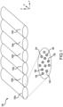
- the fabric layer 100 includes a plurality of tows 102a-102n.
- each tow of the plurality of tows 102a-102n includes a percentage of carbon fibers 104, fusible fibers 106, and fugitive fibers 108.
- each tow of the plurality of tows 102a-102n includes only carbon fibers 104.
- each tow of the plurality of tows 102a-102n includes carbon fibers 104 and either fusible fibers 106 or fugitive fibers 108. In various embodiments, each tow of the plurality of tows 102a-102n includes carbon fibers 104, fusible fibers 106, and fugitive fibers 108. In various embodiments, in a particular fabric layer 100, each tow of the plurality of tows 102a-102n includes the same percentage of carbon fibers 104, fusible fibers 106, and/or fugitive fibers 108.
- one or more tows of the plurality of tows 102a-102n may include a different percentage of carbon fibers 104, fusible fibers 106, and/or fugitive fibers 108 than another one or more tows of the plurality of tows 102a-102n.
- the fabric layer 100 has a directionality that coincides with the direction of the tows 102a-102n.
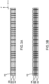
- each of fabric layers 202, 204, 206, and 208 may have consistent percentages of fugitive fibers, fusible fibers, and/or carbon fibers.
- each of fabric layers 202, 204, 206, and 208 may include fugitive fibers and carbon fibers where a ratio of fugitive fibers to carbon fibers may be 1:2, 1:3, or 1:4, among others, as long as the carbon fiber percentage is larger than the fugitive fiber percentage.
- each of fabric layers 202, 204, 206, and 208 may include fugitive fibers and fusible fibers, where a ratio of fugitive fibers to fusible fibers may be 1:2, 1:3, or 1:4, among others, as long as the fusible fiber percentage is larger than the fugitive fiber percentage.
- each of fabric layers 202, 204, 206, and 208 may include fugitive fibers, carbon fibers, and fusible fibers, where a ratio of fugitive fibers to carbon fibers to fusible fibers may be 1:2:2, 1:3:2, 1:2:3, 1:3:3, or 1:4:2, among others, as long as the carbon fiber and fusible fiber percentages are larger than the fugitive fiber percentage.
- a ratio of fugitive fibers to carbon fibers to fusible fibers may be 1:2:2, 1:3:2, 1:2:3, 1:3:3, or 1:4:2, among others, as long as the carbon fiber and fusible fiber percentages are larger than the fugitive fiber percentage.
- fabric layers 202 and 208 may have a same percentage of fugitive fibers, fusible fibers, and/or carbon fibers and fabric layers 204 and 206, while having a same percentage of fugitive fibers, fusible fibers, and/or carbon fibers, may have a different percentage of fugitive fibers, fusible fibers, and/or carbon fibers from fabric layers 202 and 208.
- fabric layers 202, 204, 206, and 208 may be joined through thickness reinforcement (TTR) via external needling, tufting, stitching, or z-pinning, among others.
- TTR thickness reinforcement
- the TTR utilizes a commingled fiber thread 210 that includes fugitive fibers, fusible fibers, and/or carbon fibers.
- commingled fiber thread 210 includes fugitive fibers and carbon fibers where a ratio of fugitive fibers to carbon fibers may be 1:2, 1:3, or 1:4, among others, as long as the carbon fiber percentage is larger than the fugitive fiber percentage.
- commingled fiber thread 210 includes fugitive fibers and fusible fibers, where a ratio of fugitive fibers to fusible fibers may be 1:2, 1:3, or 1:4, among others, as long as the fusible fiber percentage is larger than the fugitive fiber percentage.
- commingled fiber thread 210 includes fugitive fibers, carbon fibers, and fusible fibers, where a ratio of fugitive fibers to carbon fibers to fusible fibers may be 1:2:2, 1:3:2, 1:2:3, 1:3:3, or 1:4:2, among others, as long as the carbon fiber and fusible fiber percentages are larger than the fugitive fiber percentage.
- the TTR is performed in a uniform manner such that a number of needles, tufts, stiches, or z-pins are consistent along a length of the fabric layers 202, 204, 206, and 208 in the x-direction.
- a transport depth in the z-direction of the TTR is through all the fabric layers 202, 204, 206, and 208 of the commingled fiber preform for the length of the commingled fiber preform in the x-direction.
- generating a commingled fiber preform in this manner takes advantage of random fugitive fiber placement for uniform densification in through thickness direction, while maintaining high in-plane strengths.
- each of fabric layers 302, 304, 306, and 308 may have a consistent percentage of fugitive fibers, fusible fibers, and/or carbon fibers.
- each of fabric layers 302, 304, 306, and 308 may include fugitive fibers and carbon fibers where a ratio of fugitive fibers to carbon fibers may be 1:2, 1:3, or 1:4, among others, as long as the carbon fiber percentage is larger than the fugitive fiber percentage.
- each of fabric layers 302, 304, 306, and 308 may include fugitive fibers and fusible fibers, where a ratio of fugitive fibers to fusible fibers may be 1:2, 1:3, or 1:4, among others, as long as the fusible fiber percentage is larger than the fugitive fiber percentage.
- each of fabric layers 302, 304, 306, and 308 may include fugitive fibers, carbon fibers, and fusible fibers, where a ratio of fugitive fibers to carbon fibers to fusible fibers may be 1:2:2, 1:3:2, 1:2:3, 1:3:3, or 1:4:2, among others, as long as the carbon fiber and fusible fiber percentages are larger than the fugitive fiber percentage.
- a ratio of fugitive fibers to carbon fibers to fusible fibers may be 1:2:2, 1:3:2, 1:2:3, 1:3:3, or 1:4:2, among others, as long as the carbon fiber and fusible fiber percentages are larger than the fugitive fiber percentage.
- fabric layers 302 and 308 may have a same percentage of fugitive fibers, fusible fibers, and/or carbon fibers and fabric layers 304 and 306, while having a same percentage of fugitive fibers, fusible fibers, and/or carbon fibers, may have a different percentage of fugitive fibers, fusible fibers, and/or carbon fibers from fabric layers 302 and 308.
- fabric layers 302, 304, 306, and 308 may be joined through thickness reinforcement (TTR) via external needling, tufting, stitching, or z-pinning, among others.
- TTR thickness reinforcement
- the TTR utilizes a commingled fiber thread 310 that includes fugitive fibers, fusible fibers, and/or carbon fibers.
- commingled fiber thread 310 includes fugitive fibers and carbon fibers, where a ratio of fugitive fibers to carbon fibers may be 1:2, 1:3, or 1:4, among others, as long as the carbon fiber percentage is larger than the fugitive fiber percentage.
- commingled fiber thread 310 includes fugitive fibers and fusible fibers, where a ratio of fugitive fibers to fusible fibers may be 1:2, 1:3, or 1:4, among others, as long as the fusible fiber percentage is larger than the fugitive fiber percentage.
- commingled fiber thread 310 includes fugitive fibers, carbon fibers, and fusible fibers, where a ratio of fugitive fibers to carbon fibers to fusible fibers may be 1:2:2, 1:3:2, 1:2:3, 1:3:3, or 1:4:2, among others, as long as the carbon fiber and fusible fiber percentages are larger than the fugitive fiber percentage.
- the through thickness reinforcement is performed in a random manner such that a number of needles, tufts, stiches, or z-pins vary along a length of the fabric layers 202, 204, 206, and 208 in the x-direction.
- a transport depth in the z-direction of the TTR is though all of the fabric layers 202, 204, 206, and 208 of the commingled fiber preform for the length of the commingled fiber preform in the x-direction.
- generating a commingled fiber preform in this manner takes advantage of random fugitive fiber placement for uniform densification.
- TTR through thickness reinforcement
- the TTR utilizes a commingled fiber thread 410 that includes fugitive fibers, fusible fibers, and/or carbon fibers.
- commingled fiber thread 410 includes fugitive fibers and carbon fibers.
- commingled fiber thread 410 includes fugitive fibers and fusible fibers.
- commingled fiber thread 410 includes fugitive fibers, carbon fibers, and fusible fibers.
- TTR through thickness reinforcement
- the TTR using commingled fiber thread 512 penetrates completely through a thickness of the fabric layers 508 and 506 and partially through a thickness of the fabric layer 504 for a first portion of the length of the commingled fiber preform in the x-direction and then penetrates completely through a thickness of fabric layers 508, 506, and 504 and partially through a thickness of fabric layer 502 for a second portion of the length of the commingled fiber preform in the x-direction.
- the commingled fiber threads 510, 512, and 516 may include fugitive fibers and fusible fibers. In various embodiments, the commingled fiber threads 510, 512, and 516 may include fugitive fibers, carbon fibers, and fusible fibers. In various embodiments, generating a commingled fiber preform in this manner takes advantage of random fugitive fiber placement for targeted densification in through thickness direction, while maintaining high in-plane strengths.
- the multi-axial non-woven commingled fiber preform 600 includes a first fabric layer 602 positioned such that its directionality, which coincides with the direction of the tows, is at a first angle, i.e. -45 degrees with respect to the x-axis.
- a second fabric layer 604 is laid on top of the first fabric layer 602 and positioned such that its directionality is at a second angle, i.e. 90 degrees with respect to the x-axis.
- a third fabric layer 606 is laid on top of the second fabric layer 604 and positioned such that its directionality is at a third angle, i.e. +45 degrees with respect to the x-axis.
- a fourth fabric layer 608 is laid on top of the third fabric layer 609 and positioned such that its directionality is at the second angle, i.e. 90 degrees with respect to the x-axis.
- a fifth fabric layer 610 is laid on top of the fourth fabric layer 608 and positioned such that its directionality is at a fourth angle, i.e. 0 degrees with respect to the x-axis.
- the multi-axial non-woven commingled fiber preform 600 that includes fabric layers 602-610 provides for each fabric layer to be tailored dependent on the location within the commingled fiber preform and whether high or low warp strength is required.
- the multi-axial non-woven commingled fiber preform 600 is ideal for complex shapes which may require laying up on complex contour surfaces, where warp strength differentials may be preferred, which allows for the tailoring of in-plane strengths in certain directions and in certain regions.
- the multi-axial non-woven commingled fiber preform 600 that includes fabric layers 602-610 undergoes through thickness reinforcement (TTR) such as the TTR described in FIGS. 2A, 2B , 3A, 3B , 4, and 5 .
- TTR thickness reinforcement
- the TTR utilizes a commingled fiber thread 612 that includes fugitive fibers, fusible fibers, and/or carbon fibers.
- commingled fiber thread 612 includes fugitive fibers and carbon fibers.
- commingled fiber thread 612 includes fugitive fibers and fusible fibers.
- commingled fiber thread 612 includes fugitive fibers, carbon fibers, and fusible fibers.
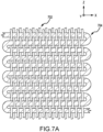
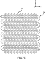
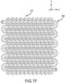
- a woven fabric for use as a fabric layer to be utilized in the embodiments of FIGS. 2A, 2B , 3A, 3B , 4, 5 , and 6 is illustrated.
- commingled fibers in the warp direction i.e. in a first direction in the y-direction may include fugitive fibers, fusible fibers, and/or carbon fibers.
- commingled fibers in the warp direction i.e. in a second direction in the x-direction may also include fugitive fibers, fusible fibers, and/or carbon fibers.
- commingled fibers in the warp or weft directions may include fugitive fibers and carbon fibers where a ratio of fugitive fibers to carbon fibers may be 1:2, 1:3, or 1:4, among others, as long as the carbon fiber percentage is larger than the fugitive fiber percentage.
- commingled fibers in the warp or weft directions may include fugitive fibers and fusible fibers, where a ratio of fugitive fibers to fusible fibers may be 1:2, 1:3, or 1:4, among others, as long as the fusible fiber percentage is larger than the fugitive fiber percentage.
- commingled fibers in the warp or weft directions may include fugitive fibers, carbon fibers, and fusible fibers, where a ratio of fugitive fibers to carbon fibers to fusible fibers may be 1:2:2, 1:3:2, 1:2:3, 1:3:3, or 1:4:2, among others, as long as the carbon fiber and fusible fiber percentages are larger than the fugitive fiber percentage.
- the commingled fibers 702 in the warp direction include fusible fibers and fugitive fibers and the commingled fibers 704 in the weft direction include only carbon fibers.
- the commingled fibers 702 in the warp direction include fusible fibers and fugitive fibers and the commingled fibers 706 in the weft direction include carbon fibers and fusible fibers.
- the commingled fibers 708 in the warp direction include carbon fibers and fugitive fibers and the commingled fibers 704 in the weft direction include only carbon fibers.
- FIG. 7A the commingled fibers 702 in the warp direction include fusible fibers and fugitive fibers and the commingled fibers 704 in the weft direction include only carbon fibers.
- the commingled fibers 708 in the warp direction include carbon fibers and fugitive fibers and the commingled fibers 706 in the weft direction include carbon fibers and fusible fibers.
- the commingled fibers 710 in the warp direction include carbon fibers, fusible fibers, and fugitive fibers and the commingled fibers 704 in the weft direction include only carbon fibers.
- the commingled fibers 710 in the warp direction include carbon fibers, fusible fibers, and fugitive fibers and the commingled fibers 706 in the weft direction include carbon fibers and fusible fibers.
- tailoring of in-plane strengths of the fabric layer in certain directions may result in the creation of a quasi-unidirectional fabric layer in a finished composite.
- changing the mix of carbon fibers and fusible fibers in the weft directions may provide for an advantageous strength differential between warp and weft directions.
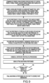
- a method of forming a commingled fiber preform for a high temperature composite is illustrated.
- commingled fibers using desired percentages of fugitive fibers, fusible fibers, and/or carbon fibers are fabricated into a fabric layers of either woven fabric layers, a non-crimp fabric layers, such as unidirectional or stitched unidirectional, or a felt fabric layers.
- the fabric layers are stacked, in a near net shape tool, with each successive layer containing the desired fiber percentages of fugitive fibers, fusible fibers, and/or carbon fibers thereby forming a commingled fiber preform.
- the various fabric layers may be joined through thickness reinforcement (TTR) via needling, tufting, stitching, or z-pinning, using a commingled fiber thread that includes fugitive fibers, fusible fibers, and/or carbon fibers.
- TTR thickness reinforcement
- the commingled fiber preform may be placed in a close die mold or vacuum bag tooling and subjected to heat and pressure to consolidate the commingled fiber preform allowing the fusible and fugitive fibers to wet out into the carbon fiber and create a path through the thickness for infiltration of fluids.
- the commingled fiber preform undergoes pyrolysis where the fugitive fibers in the commingled fiber preform are burned, melted, or evaporated, and the fusible fibers are pyrolyzed into a carbon matrix.
- the commingled fiber preform may undergo Chemical Vapor Infiltration (CVI) densification.
- CVI Chemical Vapor Infiltration
- the commingled fiber preform may undergo skim cut machining where the surface of the commingled fiber preform modified to meet a set of standards for the commingled fiber preform.
- a method of forming a commingled fiber preform for a high temperature composite is illustrated.
- commingled fibers using desired percentages of fugitive fibers, fusible fibers, and/or carbon fibers are fabricated into a fabric layers of either woven fabric layers, a non-crimp fabric layers, such as unidirectional or stitched unidirectional, or a felt fabric layers.
- the fabric layers are stacked, in a near net shape tool, with each successive layer containing the desired fiber percentages of fugitive fibers, fusible fibers, and/or carbon fibers thereby forming a commingled fiber preform.
- the various fabric layers may be joined through thickness reinforcement (TTR) via needling, tufting, stitching, or z-pinning, using a commingled fiber thread that includes fugitive fibers, fusible fibers, and/or carbon fibers.
- TTR thickness reinforcement
- the commingled fiber preform may be placed in a close die mold or vacuum bag tooling and subjected to heat and pressure to consolidate the commingled fiber preform allowing the fusible and fugitive fibers to wet out into the carbon fiber and create a path through the thickness for infiltration of fluids.
- the commingled fiber preform may undergo polymer infiltration where a thermoset resin, i.e. fluids, such as phenolic is injected into the commingled fiber preform and then cured.
- a thermoset resin i.e. fluids, such as phenolic
- the commingled fiber preform undergoes pyrolysis where the fugitive fibers in the commingled fiber preform are burned, melted, or evaporated out, and the fusible fibers are pyrolyzed into a carbon matrix.
- the commingled fiber preform may undergo Chemical Vapor Infiltration (CVI) densification.
- CVI Chemical Vapor Infiltration
- the commingled fiber preform may undergo skim cut machining where the surface of the commingled fiber preform modified to meet a set of standards for the commingled fiber preform.
- the commingled fiber preform may undergo polymer infiltration where a thermoset resin such as phenolic is injected into the commingled fiber preform and then cured.
- a thermoset resin such as phenolic
- the commingled fiber preform may undergo pyrolysis where the fugitive fibers in the commingled fiber preform are burned, melted, or evaporated out, and the fusible fibers are pyrolyzed into a carbon matrix.
- the commingled fiber preform may undergoes Chemical Vapor Infiltration (CVI) densification.
- CVI Chemical Vapor Infiltration
- the commingled fiber preform may undergo skim cut machining where the surface of the commingled fiber preform modified to meet a set of standards for the commingled fiber preform.
- the polymer infiltration, the pyrolysis, CVI densification and skim cutting may be repeated until a desired part density is reached.
- a final machining may be performed on the commingled fiber preform to meet desired commingled fiber preform dimensions.
- the illustrative embodiments provide for the creation of complex contour fibrous preforms, with a variety of thicknesses, which take advantage of commingled fibers.
- Carbon and fugitive commingled fibers enable the commingled fiber preform to take advantage of high strength properties from the carbon fibers, and yield more uniform densification than traditional carbon fiber preforms.
- the addition of carbon and fusible commingled fibers enable higher densification yields in thick sections or complex contour geometries.
- references to "one embodiment,” “an embodiment,” “various embodiments,” etc. indicate that the embodiment described may include a particular feature, structure, or characteristic, but every embodiment may not necessarily include the particular feature, structure, or characteristic. Moreover, such phrases are not necessarily referring to the same embodiment. Further, when a particular feature, structure, or characteristic is described in connection with an embodiment, it is submitted that it is within the knowledge of one skilled in the art to affect such feature, structure, or characteristic in connection with other embodiments whether or not explicitly described. After reading the description, it will be apparent to one skilled in the relevant art(s) how to implement the disclosure in alternative embodiments.
- Numbers, percentages, or other values stated herein are intended to include that value, and also other values that are about or approximately equal to the stated value, as would be appreciated by one of ordinary skill in the art encompassed by various embodiments of the present disclosure.
- a stated value should therefore be interpreted broadly enough to encompass values that are at least close enough to the stated value to perform a desired function or achieve a desired result.
- the stated values include at least the variation to be expected in a suitable industrial process, and may include values that are within 10%, within 5%, within 1%, within 0.1%, or within 0.01% of a stated value.
- the terms “substantially,” “about,” or “approximately” as used herein represent an amount close to the stated amount that still performs a desired function or achieves a desired result.
- the term “substantially,” “about,” or “approximately” may refer to an amount that is within 10% of, within 5% of, within 1% of, within 0.1% of, and within 0.01% of a stated amount or value
Landscapes
- Engineering & Computer Science (AREA)
- Textile Engineering (AREA)
- Chemical & Material Sciences (AREA)
- Mechanical Engineering (AREA)
- Inorganic Chemistry (AREA)
- Ceramic Engineering (AREA)
- Thermal Sciences (AREA)
- Physics & Mathematics (AREA)
- Composite Materials (AREA)
- Chemical Kinetics & Catalysis (AREA)
- Manufacturing & Machinery (AREA)
- Materials Engineering (AREA)
- Structural Engineering (AREA)
- Organic Chemistry (AREA)
- Nonwoven Fabrics (AREA)
Abstract
A preform is provided. The preform includes first fabric layers (202, 208) that include a first set of commingled fibers and a second set of commingled fibers. The preform includes a second fabric layer (204; 206) positioned between the first fabric layers (202, 208). The second fabric layer (204; 206) includes a third set of commingled fibers and a fourth set of commingled fibers. The first set of commingled fibers includes a lower percentage of the at least one of first carbon fibers or first fusible fibers than the third set of commingled fibers. The first set of commingled fibers include a higher percentage of first fugitive fibers than the third set of commingled fibers. The first fugitive fibers and the third fugitive fibers are pyrolyzed from the first fabric layers (202, 208) and the second fabric layer (204; 206).
Description
- The present disclosure relates generally to composite preform components and, more particularly, to a commingled fiber preform architecture for high temperature composites.
- Shaped composite bodies are utilized in aerospace applications. Various systems and methods are known in the art for forming a preform into a shaped composite body. In typical carbon-carbon manufacturing, a dry fabric may be used to make a preform. The dry preform is then densified using gas infiltration. There are many variables that determine the success of the densification stage, including the number of available pathways for the gas to infiltrate uniformly into the center of the preform.
- According to an aspect of the present invention, a preform is provided. The preform includes first fabric layers. The first fabric layers include a first set of commingled fibers and a second set of commingled fibers. The first set of commingled fibers includes at least one of first carbon fibers or first fusible fibers commingled with first fugitive fibers. The second set of commingled fibers includes second carbon fibers. The first set of commingled fibers is arranged in a first direction with the second set of commingled fibers is arranged in a second direction. The preform includes a second fabric layer positioned between the first fabric layers. The second fabric layer includes a third set of commingled fibers and a fourth set of commingled fibers. The third set of commingled fibers includes at least one of third carbon fibers or third fusible fibers commingled with third fugitive fibers. The fourth set of commingled fibers includes fourth carbon fibers. The third set of commingled fibers is arranged in the first direction with the fourth set of commingled fibers is arranged in the second direction. The first set of commingled fibers include a higher percentage of first fugitive fibers than the third set of commingled fibers. The first fugitive fibers and the third fugitive fibers are pyrolyzed from the first fabric layers and the second fabric layer to create a path through a thickness of the first fabric layers and the second fabric layer for infiltration of fluids.
- In various embodiments, the first set of commingled fibers include a lower percentage of the at least one of first carbon fibers or first fusible fibers than the third set of commingled fibers. In various embodiments, a percentage of at least one of the first carbon fibers or the first fusible fibers exceeds a percentage of the first fugitive fibers in the first set of commingled fibers. In various embodiments, a percentage of at least one of the third carbon fibers or the third fusible fibers exceeds a percentage of the third fugitive fibers in the third set of commingled fibers. In various embodiments, the second set of commingled fibers further comprise second fusible fibers. In various embodiments, the fourth set of commingled fibers further comprise fourth fusible fibers. In various embodiments, the second set of commingled fibers further comprise second fugitive fibers and the second fugitive fibers are pyrolyzed from the fabric layer. in various embodiments, the fourth set of commingled fibers further comprise fourth fugitive fibers and the fourth fugitive fibers are pyrolyzed from the second fabric layer. In various embodiments, a percentage of the second carbon fibers in the second set of commingled fibers exceeds a percentage of the second fugitive fibers in the second set of commingled fibers. In various embodiments, a percentage of the fourth carbon fibers in the fourth set of commingled fibers exceeds a percentage of the fourth fugitive fibers in the fourth set of commingled fibers.
- In various embodiments, the second set of commingled fibers further comprise second fusible fibers and second fugitive fibers and the second fugitive fibers are pyrolyzed from the fabric layer. In various embodiments, the fourth set of commingled fibers further comprise fourth fusible fibers and fourth fugitive fibers and the fourth fugitive fibers are pyrolyzed from the second fabric layer. In various embodiments, a percentage of the second carbon fibers in the second set of commingled fibers exceeds a percentage of the second fugitive fibers in the second set of commingled fibers. In various embodiments, a percentage of the fourth carbon fibers in the fourth set of commingled fibers exceeds a percentage of the fourth fugitive fibers in the fourth set of commingled fibers.
- In various embodiments, responsive to the first carbon fibers being commingled with the first fugitive fibers, a percentage of the first carbon fibers in the first set of commingled fibers exceeds a percentage of the first fugitive fibers in the first set of commingled fibers. In various embodiments, responsive to the third carbon fibers being commingled with the third fugitive fibers, a percentage of the third carbon fibers in the third set of commingled fibers exceeds a percentage of the third fugitive fibers in the third set of commingled fibers. In various embodiments, responsive to the first fusible fibers being commingled with the first fugitive fibers, a percentage of the first fusible fibers in the first set of commingled fibers exceeds a percentage of the first fugitive fibers in the first set of commingled fibers. In various embodiments, responsive to the third fusible fibers being commingled with the third fugitive fibers, a percentage of the third fusible fibers in the third set of commingled fibers exceeds a percentage of the third fugitive fibers in the third set of commingled fibers. In various embodiments, responsive to the first carbon fibers and the first fusible fibers being commingled with the first fugitive fibers, a percentage of the first carbon fibers in the first set of commingled fibers exceeds a percentage of the first fugitive fibers in the first set of commingled fibers. In various embodiments, responsive to the third carbon fibers and the third fusible fibers being commingled with the third fugitive fibers, a percentage of the third carbon fibers in the third set of commingled fibers exceeds a percentage of the third fugitive fibers in the third set of commingled fibers.
- According to an aspect of the present invention, a manufacturing method is provided. The method includes forming first fabric layers for a commingled fiber preform by weaving a first set of commingled fibers in a first direction with a second set of commingled fibers in a second direction. The first set of commingled fibers comprises at least one of first carbon fibers or first fusible fibers commingled with first fugitive fibers. The second set of commingled fibers comprises second carbon fibers. The method includes forming a second fabric layer for the commingled fiber preform by weaving a third set of commingled fibers in the first direction with a fourth set of commingled fibers in the second direction. The third set of commingled fibers includes at least one of third carbon fibers or third fusible fibers commingled with third fugitive fibers. The fourth set of commingled fibers includes fourth carbon fibers, The method includes positioning the second fabric layer between the first fabric layers. The first set of commingled fibers include a higher percentage of first fugitive fibers than the third set of commingled fibers. The first fugitive fibers and the third fugitive fibers are pyrolyzed from the first fabric layers and the second fabric layer to create a path through a thickness of the first fabric layers and the second fabric layer for infiltration of fluids.
- In various embodiments, the first set of commingled fibers include a lower percentage of the at least one of first carbon fibers or first fusible fibers than the third set of commingled fibers. In various embodiments, a percentage of at least one of the first carbon fibers or the first fusible fibers exceeds a percentage of the first fugitive fibers in the first set of commingled fibers. In various embodiments, a percentage of at least one of the third carbon fibers or the third fusible fibers exceeds a percentage of the third fugitive fibers in the third set of commingled fibers. In various embodiments, the second set of commingled fibers further comprise second fusible fibers. In various embodiments, the fourth set of commingled fibers further comprise fourth fusible fibers. In various embodiments, the second set of commingled fibers further comprise second fugitive fibers and the second fugitive fibers are pyrolyzed from the fabric layer. in various embodiments, the fourth set of commingled fibers further comprise fourth fugitive fibers and the fourth fugitive fibers are pyrolyzed from the second fabric layer. In various embodiments, a percentage of the second carbon fibers in the second set of commingled fibers exceeds a percentage of the second fugitive fibers in the second set of commingled fibers. In various embodiments, a percentage of the fourth carbon fibers in the fourth set of commingled fibers exceeds a percentage of the fourth fugitive fibers in the fourth set of commingled fibers.
- In various embodiments, the second set of commingled fibers further comprise second fusible fibers and second fugitive fibers and the second fugitive fibers are pyrolyzed from the fabric layer. In various embodiments, the fourth set of commingled fibers further comprise fourth fusible fibers and fourth fugitive fibers and the fourth fugitive fibers are pyrolyzed from the second fabric layer. In various embodiments, a percentage of the second carbon fibers in the second set of commingled fibers exceeds a percentage of the second fugitive fibers in the second set of commingled fibers. In various embodiments, a percentage of the fourth carbon fibers in the fourth set of commingled fibers exceeds a percentage of the fourth fugitive fibers in the fourth set of commingled fibers.
- In various embodiments, responsive to the first carbon fibers being commingled with the first fugitive fibers, a percentage of the first carbon fibers in the first set of commingled fibers exceeds a percentage of the first fugitive fibers in the first set of commingled fibers. In various embodiments, responsive to the third carbon fibers being commingled with the third fugitive fibers, a percentage of the third carbon fibers in the third set of commingled fibers exceeds a percentage of the third fugitive fibers in the third set of commingled fibers. In various embodiments, responsive to the first fusible fibers being commingled with the first fugitive fibers, a percentage of the first fusible fibers in the first set of commingled fibers exceeds a percentage of the first fugitive fibers in the first set of commingled fibers. In various embodiments, responsive to the third fusible fibers being commingled with the third fugitive fibers, a percentage of the third fusible fibers in the third set of commingled fibers exceeds a percentage of the third fugitive fibers in the third set of commingled fibers. In various embodiments, responsive to the first carbon fibers and the first fusible fibers being commingled with the first fugitive fibers, a percentage of the first carbon fibers in the first set of commingled fibers exceeds a percentage of the first fugitive fibers in the first set of commingled fibers. In various embodiments, responsive to the third carbon fibers and the third fusible fibers being commingled with the third fugitive fibers, a percentage of the third carbon fibers in the third set of commingled fibers exceeds a percentage of the third fugitive fibers in the third set of commingled fibers.
- According to an aspect of the present invention, a compositionally gradient preform is provided. The compositionally gradient preform includes a gradient comprising fusible fibers and fugitive fibers. The compositionally gradient preform has a plurality of fabric layers. A percentage of the fusible fibers sequentially decreases from one fabric layer in the plurality of fabric layers to a next fabric layer in the plurality of fabric layers in a direction starting from a center fabric layer in the plurality of fabric layers to surface layers in the plurality of fabric layers. A percentage of the fugitive fibers sequentially increases from the one fabric layer in the plurality of fabric layers to the next fabric layer in the plurality of fabric layers in a direction starting from the central fabric layer in the plurality of fabric layers to the surface layers in the plurality of fabric layers.
- The present disclosure may include any one or more of the individual features disclosed above and/or below alone or in any combination thereof.
- The foregoing features and elements may be combined in various combinations without exclusivity, unless expressly indicated herein otherwise. These features and elements as well as the operation of the disclosed embodiments will become more apparent in light of the following description and accompanying drawings.
-
-
FIG. 1 illustrates a fabric layer formed using commingled fibers including percentages of fugitive fibers, fusible fibers, and/or carbon fibers, in accordance with various embodiments. -
FIGS. 2A and 2B illustrate a commingled fiber preform using commingled fiber fabric layers, in accordance with various embodiments. -
FIGS. 3A and 3B illustrate a commingled fiber preform using commingled fiber fabric layers, in accordance with various embodiments. -
FIG. 4 illustrates through thickness reinforcement (TTR) of a commingled fiber preform where a transport depth coincides with the number of fabric layers added to the preform, in accordance with various embodiments. -
FIG. 5 illustrates through thickness reinforcement (TTR) of a commingled fiber preform where a transport depth of the TTR varies with regard to a number of fabric layers as well as length of the commingled fiber preform, in accordance with various embodiments. -
FIG. 6 illustrates a multi-axial non-woven commingled fiber preform, in accordance with various embodiments. -
FIGS. 7A ,7B ,7C ,7D ,7E , and7F illustrate a woven fabric for use as a fabric layer to be utilized in the embodiments ofFIGS. 2A, 2B ,3A, 3B ,4, 5 , and6 , in accordance with various embodiments. -
FIG. 8 illustrates a method of forming a commingled fiber preform for a high temperature composite, in accordance with various embodiments. -
FIG. 9 illustrates a method of forming a commingled fiber preform for a high temperature composite, in accordance with various embodiments. - The following detailed description of various embodiments herein makes reference to the accompanying drawings, which show various embodiments by way of illustration. While these various embodiments are described in sufficient detail to enable those skilled in the art to practice the disclosure, it should be understood that other embodiments may be realized and that changes may be made without departing from the scope of the disclosure. Thus, the detailed description herein is presented for purposes of illustration only and not of limitation. Furthermore, any reference to singular includes plural embodiments, and any reference to more than one component or step may include a singular embodiment or step. Also, any reference to attached, fixed, connected, or the like may include permanent, removable, temporary, partial, full or any other possible attachment option. Additionally, any reference to without contact (or similar phrases) may also include reduced contact or minimal contact. It should also be understood that unless specifically stated otherwise, references to "a," "an," or "the" may include one or more than one and that reference to an item in the singular may also include the item in the plural. Further, all ranges may include upper and lower values and all ranges and ratio limits disclosed herein may be combined.
- Various systems and methods are known in the art for generating a commingled fiber preform. Commingled fibers and yarn typically entangle thermoplastic or thermoset fibers with carbon, glass, or other reinforcement fibers to produce a low-cost, yet highly-flexible material utilized to manufacture components with complex geometries. In typical carbon-carbon manufacturing, a commingled fiber preform may be manufactured and this commingled fiber preform may then be densified using gas infiltration. There are many variables that determine the success of the densification stage, including the number of available pathways for the gas to infiltrate uniformly into the center of the commingled fiber preform. Typically, fiber volume and lack of adequate gas flow paths inhibit uniform densification and yield a component with less than 10 percent open porosity.
- Disclosed herein are systems and methods for a commingled fiber preform architecture for high temperature composites that provides numerous pathways for fluids, i.e. uniform gas, infiltration into the center of the commingled fiber preform during densification. In various embodiments, commingled fibers using desired percentages of fugitive fibers, fusible fibers, and/or carbon fibers are fabricated into a fabric layers of either woven fabric layers, a non-crimp fabric layers, such as unidirectional or stitched unidirectional, or a felt fabric layers.
- As used herein, a fusible fiber is comprised of one or more polymers with a combined char yield of 25% or greater by weight and a residual mass of less than 1% by weight. As used herein, a fugitive fiber is comprised of one or more polymers with a combined char yield of 5% or less by weight, and a residual mass of less than 1% by weight. As used herein, char yield is defined as the percentage of weight remaining when the fiber material is heated (or pyrolyzed) in an inert atmosphere (e.g., nitrogen or argon) at temperatures of up to about 1000 degrees Celsius (about 1832 degrees Fahrenheit). As used herein, residual mass is defined as the percentage of weight remaining when the fiber material is heated (or oxidized) in an oxidizing atmosphere (e.g., air, or oxygen) at temperatures of up to about 1000 degrees Celsius (about 1832 degrees Fahrenheit). It should be noted that while a residual mass of 1% or less is preferred in the production of carbon-carbon composite structures for high temperature applications, a residual mass of greater than 1% may be acceptable for certain lower temperature applications.
- In various embodiments, carbon fibers may include a variety of carbon moduli but, for flexibility during preform lay-up, standard or intermediate modulus carbon fibers may be preferred. In various embodiments, carbon fibers are comprised of 85% of carbon by weight or greater. In various embodiments, fugitive fibers may include fibers without harmful byproducts that, responsive to being burned, burn under carbon-carbon processing temperatures, e.g. under 800 degrees Celsius (1472 degrees Fahrenheit). In that regard, fugitive fibers may be made of polyvinyl alcohol (PVA), polyethylene terephthalate (PET), nylon, polyethylene (PE), polyamide imide (PAI), or similar plastic, among others. In various embodiments, fusible fibers may include thermoplastic or thermoset fibers. In that regard, fusible fibers may include polyetheretherketone (PEEK), polyaryleetherketones (PAEK), polyetherketoneketone (PEKK), polyester imide (PEI), polyimide (PI), phenolics, pitch, or similar polymers, among others.
- In various embodiments, the fabric layers may then be stacked, in a near net shape tool, with each successive layer containing the desired fiber percentages of fugitive fibers, fusible fibers, and/or carbon fibers thereby forming a commingled fiber preform. In various embodiments, the fiber percentages may be varied such that interior plies of the commingled fiber preform may contain a higher percentage of carbon fibers and a lower percentage of fugitive fibers or fusible fibers while the exterior plies of the commingled fiber preform may conversely contain a lower percentage of carbon fibers and a higher percentage of fugitive fibers or fusible fibers. In various embodiments, during stacking, the fabric layers may be tacked together using a variety of methods, e.g. an adhesive tackifier, a hot iron to locally melt a thermoplastic, or an ultra-sonic thermoplastic welder, among others. In various embodiments, as the commingled fiber preform is stacked, the various fabric layers may be joined through thickness reinforcement (TTR) via needling, tufting, stitching, or z-pinning, using a commingled fiber thread that includes fugitive fibers, fusible fibers, and/or carbon fibers. In various embodiments, once all the fabric layers are stacked, then all the fabric layers are needled, tufted, stitched, or z-pinned together. In various embodiments, as each successive fabric layer is added, then the fabric layers may be needled, tufted, stitched, or z-pinned together. In various embodiments, the needling, tufting, stitching, or z-pinning may penetrate all the fabric layers. In various embodiments, the needling, tufting, stitching, or z-pinning may penetrate only a predefined number of fabric layers. In various embodiments, a number of fabric layers that are needled, tufted, stitched, or z-pinned may vary as the commingled fiber preform is generated. In various embodiments, once the commingled fiber preform is completely stacked and needled, the commingled fiber preform may be placed in a close die mold or vacuum bag tooling and subjected to heat and pressure to consolidate the commingled fiber preform, allowing the fusible and fugitive fibers to wet out, i.e. be completely coated, into the carbon-fiber and create a path through the thickness for infiltration of fluids.
- In various embodiments, once consolidation is complete, the commingled fiber preform may undergo pyrolysis where the fugitive fibers in the commingled fiber preform are burned, melted, or evaporated, and the fusible fibers are pyrolyzed into a carbon matrix. In various embodiments, once pyrolysis is complete, the commingled fiber preform may undergo Chemical Vapor Infiltration (CVI) densification. In various embodiments, once the CVI densification is complete, the commingled fiber preform may undergo skim cut machining where the surface of the commingled fiber preform is modified to meet a set of standards for the commingled fiber preform. In various embodiments, the pyrolysis, CVI densification and skim cutting may be repeated until a desired part density is reached. In various embodiments, once the desired part density is reached, a final machining may be performed on the commingled fiber preform to meet desired commingled fiber preform dimensions.
- In various embodiments, once consolidation is complete, the commingled fiber preform may undergo polymer infiltration where a thermoset or thermoplastic resin such as phenolic or pitch is injected into the commingled fiber preform and then cured. In various embodiments, once the thermoset resin is cured, the commingled fiber preform may undergo pyrolysis where the fugitive fibers in the commingled fiber preform are burned, melted, or evaporated, and the fusible fibers are pyrolyzed into a carbon matrix. In various embodiments, once pyrolysis is complete, the commingled fiber preform may undergo further densification via Chemical Vapor Infiltration (CVI) densification. In various embodiments, once the CVI densification is complete, the commingled fiber preform may undergo skim cut machining where the surface of the commingled fiber preform is modified to meet a set of standards for the commingled fiber preform. In various embodiments, at least one of polymer infiltration, the pyrolysis, CVI densification and skim cutting may be repeated until a desired part density is reached. In various embodiments, once the desired part density is reached, a final machining may be performed on the commingled fiber preform to meet desired commingled fiber preform dimensions.
- Referring now to
FIG. 1 , in accordance with various embodiments, a fabric layer formed using commingled fibers including percentages of fugitive fibers, fusible fibers, and/or carbon fibers is illustrated. In various embodiments, thefabric layer 100 includes a plurality oftows 102a-102n. In various embodiments, each tow of the plurality oftows 102a-102n includes a percentage ofcarbon fibers 104,fusible fibers 106, andfugitive fibers 108. In various embodiments, each tow of the plurality oftows 102a-102n includesonly carbon fibers 104. In various embodiments, each tow of the plurality oftows 102a-102n includescarbon fibers 104 and eitherfusible fibers 106 orfugitive fibers 108. In various embodiments, each tow of the plurality oftows 102a-102n includescarbon fibers 104,fusible fibers 106, andfugitive fibers 108. In various embodiments, in aparticular fabric layer 100, each tow of the plurality oftows 102a-102n includes the same percentage ofcarbon fibers 104,fusible fibers 106, and/orfugitive fibers 108. In various embodiments, in aparticular fabric layer 100, one or more tows of the plurality oftows 102a-102n may include a different percentage ofcarbon fibers 104,fusible fibers 106, and/orfugitive fibers 108 than another one or more tows of the plurality oftows 102a-102n. In various embodiments, thefabric layer 100 has a directionality that coincides with the direction of thetows 102a-102n. - Referring now to
FIGS. 2A and 2B , in accordance with various embodiments, a commingled fiber preform using commingled fiber fabric layers is illustrated. In various embodiments, as illustrated inFIG. 2A , each offabric layers fabric layers fabric layers fabric layers FIG. 2B , fabric layers 202 and 208 may have a same percentage of fugitive fibers, fusible fibers, and/or carbon fibers andfabric layers fabric layers fiber thread 210 that includes fugitive fibers, fusible fibers, and/or carbon fibers. In various embodiments, commingledfiber thread 210 includes fugitive fibers and carbon fibers where a ratio of fugitive fibers to carbon fibers may be 1:2, 1:3, or 1:4, among others, as long as the carbon fiber percentage is larger than the fugitive fiber percentage. In various embodiments, commingledfiber thread 210 includes fugitive fibers and fusible fibers, where a ratio of fugitive fibers to fusible fibers may be 1:2, 1:3, or 1:4, among others, as long as the fusible fiber percentage is larger than the fugitive fiber percentage. In various embodiments, commingledfiber thread 210 includes fugitive fibers, carbon fibers, and fusible fibers, where a ratio of fugitive fibers to carbon fibers to fusible fibers may be 1:2:2, 1:3:2, 1:2:3, 1:3:3, or 1:4:2, among others, as long as the carbon fiber and fusible fiber percentages are larger than the fugitive fiber percentage. In various embodiments, the TTR is performed in a uniform manner such that a number of needles, tufts, stiches, or z-pins are consistent along a length of the fabric layers 202, 204, 206, and 208 in the x-direction. In various embodiments, a transport depth in the z-direction of the TTR is through all the fabric layers 202, 204, 206, and 208 of the commingled fiber preform for the length of the commingled fiber preform in the x-direction. In various embodiments, generating a commingled fiber preform in this manner takes advantage of random fugitive fiber placement for uniform densification in through thickness direction, while maintaining high in-plane strengths. - Referring now to
FIGS. 3A and 3B , in accordance with various embodiments, a commingled fiber preform using commingled fiber fabric layers is illustrated. In various embodiments, as illustrated inFIG. 3A , each offabric layers fabric layers fabric layers fabric layers FIG. 3B , fabric layers 302 and 308 may have a same percentage of fugitive fibers, fusible fibers, and/or carbon fibers andfabric layers fabric layers fiber thread 310 that includes fugitive fibers, fusible fibers, and/or carbon fibers. In various embodiments, commingledfiber thread 310 includes fugitive fibers and carbon fibers, where a ratio of fugitive fibers to carbon fibers may be 1:2, 1:3, or 1:4, among others, as long as the carbon fiber percentage is larger than the fugitive fiber percentage. In various embodiments, commingledfiber thread 310 includes fugitive fibers and fusible fibers, where a ratio of fugitive fibers to fusible fibers may be 1:2, 1:3, or 1:4, among others, as long as the fusible fiber percentage is larger than the fugitive fiber percentage. In various embodiments, commingledfiber thread 310 includes fugitive fibers, carbon fibers, and fusible fibers, where a ratio of fugitive fibers to carbon fibers to fusible fibers may be 1:2:2, 1:3:2, 1:2:3, 1:3:3, or 1:4:2, among others, as long as the carbon fiber and fusible fiber percentages are larger than the fugitive fiber percentage. In various embodiments, the through thickness reinforcement (TTR) is performed in a random manner such that a number of needles, tufts, stiches, or z-pins vary along a length of the fabric layers 202, 204, 206, and 208 in the x-direction. In various embodiments, a transport depth in the z-direction of the TTR is though all of the fabric layers 202, 204, 206, and 208 of the commingled fiber preform for the length of the commingled fiber preform in the x-direction. In various embodiments, generating a commingled fiber preform in this manner takes advantage of random fugitive fiber placement for uniform densification. - Referring now to
FIG. 4 , in accordance with various embodiments, through thickness reinforcement (TTR) of a commingled fiber preform where a transport depth coincides with the number of fabric layers added to the commingled fiber preform is illustrated. In various embodiments, a transport depth in the z-direction of the TTR only penetrates a current fabric layer and an immediate previous fabric layer. In that regard, responsive tofabric layer 404 being laid on top offabric layer 402, the TTR using commingledfiber thread 410 penetrates thefabric layer 404 andfabric layer 402. Responsive tofabric layer 406 being laid on top offabric layer 404, the TTR using commingledfiber thread 410 penetrates onlyfabric layer 406 andfabric layer 404. Responsive tofabric layer 408 being laid on top offabric layer 406, the TTR using commingledfiber thread 410 penetrates onlyfabric layer 408 andfabric layer 406. Responsive tofabric layer 412 being laid on top offabric layer 408, the TTR using commingledfiber thread 410 penetrates onlyfabric layer 412 andfabric layer 408. In various embodiments, the TTR utilizes a commingledfiber thread 410 that includes fugitive fibers, fusible fibers, and/or carbon fibers. In various embodiments, commingledfiber thread 410 includes fugitive fibers and carbon fibers. In various embodiments, commingledfiber thread 410 includes fugitive fibers and fusible fibers. In various embodiments, commingledfiber thread 410 includes fugitive fibers, carbon fibers, and fusible fibers. - Referring now to
FIG. 5 , in accordance with various embodiments, through thickness reinforcement (TTR) of a commingled fiber preform where a transport depth of the TTR varies with regard to a number of fabric layers as well as length of the commingled fiber preform is illustrated. In various embodiments, responsive tofabric layer 504 being laid on top offabric layer 502, the TTR using commingledfiber thread 510 penetrates completely through a thickness of thefabric layer 504 and partially through a thickness offabric layer 502 but only for a portion of the length of the commingled fiber preform in the x-direction. Responsive tofabric layer 506 being laid on top offabric layer 504 and thenfabric layer 508 being laid on top offabric layer 506, the TTR using commingledfiber thread 512 penetrates completely through a thickness of the fabric layers 508 and 506 and partially through a thickness of thefabric layer 504 for a first portion of the length of the commingled fiber preform in the x-direction and then penetrates completely through a thickness offabric layers fabric layer 502 for a second portion of the length of the commingled fiber preform in the x-direction. Responsive tofabric layer 514 being laid on top offabric layer 508, the TTR using commingledfiber thread 516 penetrates completely through a thickness offabric layer 514 and partially though a thickness offabric layer 508 for the first portion and the second portion of the length of the commingled fiber preform in the x-direction. In various embodiments, the commingledfiber threads fiber threads fiber threads fiber threads - Referring now to
FIG. 6 , in accordance with various embodiments, a multi-axial non-woven commingled fiber preform is illustrated. In various embodiments, the multi-axial non-woven commingled fiber preform 600 includes afirst fabric layer 602 positioned such that its directionality, which coincides with the direction of the tows, is at a first angle, i.e. -45 degrees with respect to the x-axis. In various embodiments, asecond fabric layer 604 is laid on top of thefirst fabric layer 602 and positioned such that its directionality is at a second angle, i.e. 90 degrees with respect to the x-axis. In various embodiments, athird fabric layer 606 is laid on top of thesecond fabric layer 604 and positioned such that its directionality is at a third angle, i.e. +45 degrees with respect to the x-axis. In various embodiments, afourth fabric layer 608 is laid on top of the third fabric layer 609 and positioned such that its directionality is at the second angle, i.e. 90 degrees with respect to the x-axis. In various embodiments, afifth fabric layer 610 is laid on top of thefourth fabric layer 608 and positioned such that its directionality is at a fourth angle, i.e. 0 degrees with respect to the x-axis. In various embodiments, the multi-axial non-woven commingled fiber preform 600 that includes fabric layers 602-610 provides for each fabric layer to be tailored dependent on the location within the commingled fiber preform and whether high or low warp strength is required. In various embodiments, the multi-axial non-woven commingled fiber preform 600 is ideal for complex shapes which may require laying up on complex contour surfaces, where warp strength differentials may be preferred, which allows for the tailoring of in-plane strengths in certain directions and in certain regions. In various embodiments, once the multi-axial non-woven commingled fiber preform 600 that includes fabric layers 602-610 is laid up, the multi-axial non-woven commingled fiber preform undergoes through thickness reinforcement (TTR) such as the TTR described inFIGS. 2A, 2B ,3A, 3B ,4, and 5 . In various embodiments, the TTR utilizes a commingledfiber thread 612 that includes fugitive fibers, fusible fibers, and/or carbon fibers. In various embodiments, commingledfiber thread 612 includes fugitive fibers and carbon fibers. In various embodiments, commingledfiber thread 612 includes fugitive fibers and fusible fibers. In various embodiments, commingledfiber thread 612 includes fugitive fibers, carbon fibers, and fusible fibers. - Referring now to
FIGS. 7A-7F , in accordance with various embodiments, a woven fabric for use as a fabric layer to be utilized in the embodiments ofFIGS. 2A, 2B ,3A, 3B ,4, 5 , and6 is illustrated. In various embodiments, commingled fibers in the warp direction, i.e. in a first direction in the y-direction may include fugitive fibers, fusible fibers, and/or carbon fibers. Likewise, in various embodiments, commingled fibers in the warp direction, i.e. in a second direction in the x-direction may also include fugitive fibers, fusible fibers, and/or carbon fibers. In that regard, in various embodiments, commingled fibers in the warp or weft directions may include fugitive fibers and carbon fibers where a ratio of fugitive fibers to carbon fibers may be 1:2, 1:3, or 1:4, among others, as long as the carbon fiber percentage is larger than the fugitive fiber percentage. In various embodiments, commingled fibers in the warp or weft directions may include fugitive fibers and fusible fibers, where a ratio of fugitive fibers to fusible fibers may be 1:2, 1:3, or 1:4, among others, as long as the fusible fiber percentage is larger than the fugitive fiber percentage. In various embodiments, commingled fibers in the warp or weft directions may include fugitive fibers, carbon fibers, and fusible fibers, where a ratio of fugitive fibers to carbon fibers to fusible fibers may be 1:2:2, 1:3:2, 1:2:3, 1:3:3, or 1:4:2, among others, as long as the carbon fiber and fusible fiber percentages are larger than the fugitive fiber percentage. - In
FIG. 7A , the commingledfibers 702 in the warp direction include fusible fibers and fugitive fibers and the commingledfibers 704 in the weft direction include only carbon fibers. InFIG. 7B , the commingledfibers 702 in the warp direction include fusible fibers and fugitive fibers and the commingledfibers 706 in the weft direction include carbon fibers and fusible fibers. InFIG. 7C , the commingledfibers 708 in the warp direction include carbon fibers and fugitive fibers and the commingledfibers 704 in the weft direction include only carbon fibers. InFIG. 7D , the commingledfibers 708 in the warp direction include carbon fibers and fugitive fibers and the commingledfibers 706 in the weft direction include carbon fibers and fusible fibers. InFIG. 7E , the commingledfibers 710 in the warp direction include carbon fibers, fusible fibers, and fugitive fibers and the commingledfibers 704 in the weft direction include only carbon fibers. InFIG. 7F , the commingledfibers 710 in the warp direction include carbon fibers, fusible fibers, and fugitive fibers and the commingledfibers 706 in the weft direction include carbon fibers and fusible fibers. In various embodiments, tailoring of in-plane strengths of the fabric layer in certain directions, may result in the creation of a quasi-unidirectional fabric layer in a finished composite. In various embodiments, changing the mix of carbon fibers and fusible fibers in the weft directions may provide for an advantageous strength differential between warp and weft directions. - Referring now to
FIG. 8 , in accordance with various embodiments, a method of forming a commingled fiber preform for a high temperature composite is illustrated. Atblock 802, commingled fibers using desired percentages of fugitive fibers, fusible fibers, and/or carbon fibers are fabricated into a fabric layers of either woven fabric layers, a non-crimp fabric layers, such as unidirectional or stitched unidirectional, or a felt fabric layers. Atblock 804, the fabric layers are stacked, in a near net shape tool, with each successive layer containing the desired fiber percentages of fugitive fibers, fusible fibers, and/or carbon fibers thereby forming a commingled fiber preform. Atblock 806, as the commingled fiber preform is stacked, the various fabric layers may be joined through thickness reinforcement (TTR) via needling, tufting, stitching, or z-pinning, using a commingled fiber thread that includes fugitive fibers, fusible fibers, and/or carbon fibers. Atblock 808, once the commingled fiber preform is completely stacked and needled, the commingled fiber preform may be placed in a close die mold or vacuum bag tooling and subjected to heat and pressure to consolidate the commingled fiber preform allowing the fusible and fugitive fibers to wet out into the carbon fiber and create a path through the thickness for infiltration of fluids. - At
block 810, once consolidation is complete, the commingled fiber preform undergoes pyrolysis where the fugitive fibers in the commingled fiber preform are burned, melted, or evaporated, and the fusible fibers are pyrolyzed into a carbon matrix. Atblock 812, once pyrolysis is complete, the commingled fiber preform may undergo Chemical Vapor Infiltration (CVI) densification. At block 814, once the CVI densification is complete, the commingled fiber preform may undergo skim cut machining where the surface of the commingled fiber preform modified to meet a set of standards for the commingled fiber preform. At block 816 a determination is made as to whether a desired part density is reached. If atblock 816 the desired part density has not been reached, the operation returns to block 810. If atblock 816 the desired part density has been reached, then, atblock 818, a final machining may be performed on the commingled fiber preform to meet desired commingled fiber preform dimensions. - Referring now to
FIG. 9 , in accordance with various embodiments, a method of forming a commingled fiber preform for a high temperature composite is illustrated. Atblock 902, commingled fibers using desired percentages of fugitive fibers, fusible fibers, and/or carbon fibers are fabricated into a fabric layers of either woven fabric layers, a non-crimp fabric layers, such as unidirectional or stitched unidirectional, or a felt fabric layers. Atblock 904, the fabric layers are stacked, in a near net shape tool, with each successive layer containing the desired fiber percentages of fugitive fibers, fusible fibers, and/or carbon fibers thereby forming a commingled fiber preform. Atblock 906, as the commingled fiber preform is stacked, the various fabric layers may be joined through thickness reinforcement (TTR) via needling, tufting, stitching, or z-pinning, using a commingled fiber thread that includes fugitive fibers, fusible fibers, and/or carbon fibers. Atblock 908, once the commingled fiber preform is completely stacked and needled, the commingled fiber preform may be placed in a close die mold or vacuum bag tooling and subjected to heat and pressure to consolidate the commingled fiber preform allowing the fusible and fugitive fibers to wet out into the carbon fiber and create a path through the thickness for infiltration of fluids. - At
block 910, once consolidation is complete, the commingled fiber preform may undergo polymer infiltration where a thermoset resin, i.e. fluids, such as phenolic is injected into the commingled fiber preform and then cured. Atblock 912, once the thermoset resin is cured, the commingled fiber preform undergoes pyrolysis where the fugitive fibers in the commingled fiber preform are burned, melted, or evaporated out, and the fusible fibers are pyrolyzed into a carbon matrix. Atblock 914, once pyrolysis is complete, the commingled fiber preform may undergo Chemical Vapor Infiltration (CVI) densification. Atblock 916, once the CVI densification is complete, the commingled fiber preform may undergo skim cut machining where the surface of the commingled fiber preform modified to meet a set of standards for the commingled fiber preform. At block 918 a determination is made as to whether a desired part density is reached. If atblock 918 the desired part density has not been reached, the operation returns to block 910. If atblock 918 the desired part density has been reached, then, atblock 920, a final machining may be performed on the commingled fiber preform to meet desired commingled fiber preform dimensions. - In various embodiments, once consolidation is complete, the commingled fiber preform may undergo polymer infiltration where a thermoset resin such as phenolic is injected into the commingled fiber preform and then cured. In various embodiments, once the thermoset resin is cured, the commingled fiber preform may undergo pyrolysis where the fugitive fibers in the commingled fiber preform are burned, melted, or evaporated out, and the fusible fibers are pyrolyzed into a carbon matrix. In various embodiments, once pyrolysis is complete, the commingled fiber preform may undergoes Chemical Vapor Infiltration (CVI) densification. In various embodiments, once the CVI densification is complete, the commingled fiber preform may undergo skim cut machining where the surface of the commingled fiber preform modified to meet a set of standards for the commingled fiber preform. In various embodiments, the polymer infiltration, the pyrolysis, CVI densification and skim cutting may be repeated until a desired part density is reached. In various embodiments, once the desired part density is reached, a final machining may be performed on the commingled fiber preform to meet desired commingled fiber preform dimensions.
- Therefore, the illustrative embodiments provide for the creation of complex contour fibrous preforms, with a variety of thicknesses, which take advantage of commingled fibers. Carbon and fugitive commingled fibers enable the commingled fiber preform to take advantage of high strength properties from the carbon fibers, and yield more uniform densification than traditional carbon fiber preforms. The addition of carbon and fusible commingled fibers enable higher densification yields in thick sections or complex contour geometries.
- Benefits and other advantages have been described herein with regard to specific embodiments. Furthermore, the connecting lines shown in the various figures contained herein are intended to represent exemplary functional relationships and/or physical couplings between the various elements. It should be noted that many alternative or additional functional relationships or physical connections may be present in a practical system. However, the benefits, advantages, and any elements that may cause any benefit or advantage to occur or become more pronounced are not to be construed as critical, required, or essential features or elements of the disclosure. The scope of the disclosure is accordingly to be limited by nothing other than the appended claims, in which reference to an element in the singular is not intended to mean "one and only one" unless explicitly so stated, but rather "one or more." Moreover, where a phrase similar to "at least one of A, B, or C" is used in the claims, it is intended that the phrase be interpreted to mean that A alone may be present in an embodiment, B alone may be present in an embodiment, C alone may be present in an embodiment, or that any combination of the elements A, B and C may be present in a single embodiment; for example, A and B, A and C, B and C, or A and B and C.
- Systems, methods, and apparatus are provided herein. In the detailed description herein, references to "one embodiment," "an embodiment," "various embodiments," etc., indicate that the embodiment described may include a particular feature, structure, or characteristic, but every embodiment may not necessarily include the particular feature, structure, or characteristic. Moreover, such phrases are not necessarily referring to the same embodiment. Further, when a particular feature, structure, or characteristic is described in connection with an embodiment, it is submitted that it is within the knowledge of one skilled in the art to affect such feature, structure, or characteristic in connection with other embodiments whether or not explicitly described. After reading the description, it will be apparent to one skilled in the relevant art(s) how to implement the disclosure in alternative embodiments.
- Numbers, percentages, or other values stated herein are intended to include that value, and also other values that are about or approximately equal to the stated value, as would be appreciated by one of ordinary skill in the art encompassed by various embodiments of the present disclosure. A stated value should therefore be interpreted broadly enough to encompass values that are at least close enough to the stated value to perform a desired function or achieve a desired result. The stated values include at least the variation to be expected in a suitable industrial process, and may include values that are within 10%, within 5%, within 1%, within 0.1%, or within 0.01% of a stated value. Additionally, the terms "substantially," "about," or "approximately" as used herein represent an amount close to the stated amount that still performs a desired function or achieves a desired result. For example, the term "substantially," "about," or "approximately" may refer to an amount that is within 10% of, within 5% of, within 1% of, within 0.1% of, and within 0.01% of a stated amount or value.
- Furthermore, no element, component, or method step in the present disclosure is intended to be dedicated to the public regardless of whether the element, component, or method step is explicitly recited in the claims. No claim element herein is to be construed under the provisions of 35 U.S.C. 112(f) unless the element is expressly recited using the phrase "means for." As used herein, the terms "comprises," "comprising," or any other variation thereof, are intended to cover a non-exclusive inclusion, such that a process, method, article, or apparatus that comprises a list of elements does not include only those elements but may include other elements not expressly listed or inherent to such process, method, article, or apparatus.
- Finally, it should be understood that any of the above-described concepts can be used alone or in combination with any or all of the other above-described concepts. Although various embodiments have been disclosed and described, one of ordinary skill in this art would recognize that certain modifications would come within the scope of this disclosure. Accordingly, the description is not intended to be exhaustive or to limit the principles described or illustrated herein to any precise form. Many modifications and variations are possible in light of the above teaching.
Claims (15)
- A preform comprising:first fabric layers, wherein first fabric layers comprises:a first set of commingled fibers, wherein the first set of commingled fibers comprises at least one of first carbon fibers or first fusible fibers commingled with first fugitive fibers; anda second set of commingled fibers, wherein the second set of commingled fibers comprises second carbon fibers and wherein the first set of commingled fibers is arranged in a first direction with the second set of commingled fibers is arranged in a second direction; anda second fabric layer positioned between the first fabric layers, wherein the second fabric layer comprises:a third set of commingled fibers, wherein the third set of commingled fibers comprises at least one of third carbon fibers or third fusible fibers commingled with third fugitive fibers; anda fourth set of commingled fibers, wherein the fourth set of commingled fibers comprises fourth carbon fibers and wherein the third set of commingled fibers is arranged in the first direction with the fourth set of commingled fibers arranged in the second direction,wherein the first set of commingled fibers comprise a higher percentage of fugitive fibers than the third set of commingled fibers, andwherein the first fugitive fibers and the third fugitive fibers are pyrolyzed from the first fabric layers and the second fabric layer to create a path through a thickness of the first fabric layers and the second fabric layer for infiltration of fluids.
- The preform of claim 1, wherein the first set of commingled fibers comprise a lower percentage of the at least one of first carbon fibers or first fusible fibers than the third set of commingled fibers.
- The preform of claim 1 or 2, wherein a percentage of at least one of the first carbon fibers or the first fusible fibers exceeds a percentage of the first fugitive fibers in the first set of commingled fibers and wherein a percentage of at least one of the third carbon fibers or the third fusible fibers exceeds a percentage of the third fugitive fibers in the third set of commingled fibers.
- The preform of claim 1, 2 or 3, wherein the second set of commingled fibers further comprise second fusible fibers and wherein the fourth set of commingled fibers further comprise fourth fusible fibers.
- The preform of any preceding claim, wherein the second set of commingled fibers further comprise second fugitive fibers, wherein the second fugitive fibers are pyrolyzed from the first fabric layers, wherein the fourth set of commingled fibers further comprise fourth fugitive fibers, and wherein the fourth fugitive fibers are pyrolyzed from the second fabric layer.
- The preform of claim 5, wherein a percentage of the second carbon fibers in the second set of commingled fibers exceeds a percentage of the second fugitive fibers in the second set of commingled fibers and wherein a percentage of the fourth carbon fibers in the fourth set of commingled fibers exceeds a percentage of the fourth fugitive fibers in the fourth set of commingled fibers.
- The preform of any preceding claim, wherein, responsive to the first carbon fibers being commingled with the first fugitive fibers, a percentage of the first carbon fibers in the first set of commingled fibers exceeds a percentage of the first fugitive fibers in the first set of commingled fibers and wherein, responsive to the third carbon fibers being commingled with the third fugitive fibers, a percentage of the third carbon fibers in the third set of commingled fibers exceeds a percentage of the third fugitive fibers in the third set of commingled fibers.
- The preform of any preceding claim, wherein, responsive to the first fusible fibers being commingled with the first fugitive fibers, a percentage of the first fusible fibers in the first set of commingled fibers exceeds a percentage of the first fugitive fibers in the first set of commingled fibers and wherein, responsive to the third fusible fibers being commingled with the third fugitive fibers, a percentage of the third fusible fibers in the third set of commingled fibers exceeds a percentage of the third fugitive fibers in the third set of commingled fibers.
- The preform of any preceding claim, wherein, responsive to the first carbon fibers and the first fusible fibers being commingled with the first fugitive fibers, a percentage of the first carbon fibers in the first set of commingled fibers exceeds a percentage of the first fugitive fibers in the first set of commingled fibers and wherein, responsive to the third carbon fibers and the third fusible fibers being commingled with the third fugitive fibers, a percentage of the third carbon fibers in the third set of commingled fibers exceeds a percentage of the third fugitive fibers in the third set of commingled fibers.
- A manufacturing method, comprising:forming first fabric layers for a commingled fiber preform by arranging a first set of commingled fibers in a first direction with a second set of commingled fibers in a second direction, wherein the first set of commingled fibers comprises at least one of first carbon fibers or first fusible fibers commingled with first fugitive fibers and wherein the second set of commingled fibers comprises second carbon fibers;forming a second fabric layer for the commingled fiber preform by arranging a third set of commingled fibers in the first direction with a fourth set of commingled fibers in the second direction, wherein the third set of commingled fibers comprises at least one of third carbon fibers or third fusible fibers commingled with third fugitive fibers and wherein the fourth set of commingled fibers comprises fourth carbon fibers; andpositioning the second fabric layer between the first fabric layers,wherein the first set of commingled fibers comprise a lower percentage of the at least one of first carbon fibers or first fusible fibers than the third set of commingled fibers,wherein the first set of commingled fibers comprise a higher percentage of fugitive fibers than the third set of commingled fibers, andwherein the first fugitive fibers and the third fugitive fibers are pyrolyzed from the first fabric layers and the second fabric layer to create a path through a thickness of the first fabric layers and the second fabric layer for infiltration of fluids.
- The manufacturing method of claim 10, wherein the first set of commingled fibers comprise a lower percentage of the at least one of first carbon fibers or first fusible fibers than the third set of commingled fibers.
- The manufacturing method of claim 10 or 11, wherein a percentage of at least one of the first carbon fibers or the first fusible fibers exceeds a percentage of the first fugitive fibers in the first set of commingled fibers and wherein a percentage of at least one of the third carbon fibers or the third fusible fibers exceeds a percentage of the third fugitive fibers in the third set of commingled fibers.
- The manufacturing method of claim 10, 11 or 12, wherein the second set of commingled fibers further comprise second fusible fibers and wherein the fourth set of commingled fibers further comprise fourth fusible fibers; and/orwherein the second set of commingled fibers further comprise second fugitive fibers, wherein the second fugitive fibers are pyrolyzed from the first fabric layers, wherein the fourth set of commingled fibers further comprise fourth fugitive fibers, wherein the fourth fugitive fibers are pyrolyzed from the second fabric layer, wherein a percentage of the second carbon fibers in the second set of commingled fibers exceeds a percentage of the second fugitive fibers in the second set of commingled fibers and wherein a percentage of the fourth carbon fibers in the fourth set of commingled fibers exceeds a percentage of the fourth fugitive fibers in the fourth set of commingled fibers; and/orwherein the second set of commingled fibers further comprise second fusible fibers and second fugitive fibers, wherein the second fugitive fibers are pyrolyzed from the fabric layer, wherein the fourth set of commingled fibers further comprise fourth fusible fibers and fourth fugitive fibers, and wherein the fourth fugitive fibers are pyrolyzed from the second fabric layer, wherein a percentage of the second carbon fibers in the second set of commingled fibers exceeds a percentage of the second fugitive fibers in the second set of commingled fibers and wherein a percentage of the fourth carbon fibers in the fourth set of commingled fibers exceeds a percentage of the fourth fugitive fibers in the fourth set of commingled fibers.
- The manufacturing method of any of claims 10 to 13, wherein, responsive to the first carbon fibers being commingled with the first fugitive fibers, a percentage of the first carbon fibers in the first set of commingled fibers exceeds a percentage of the first fugitive fibers in the first set of commingled fibers and wherein, responsive to the third carbon fibers being commingled with the third fugitive fibers, a percentage of the third carbon fibers in the third set of commingled fibers exceeds a percentage of the third fugitive fibers in the third set of commingled fibers; and / orwherein, responsive to the first fusible fibers being commingled with the first fugitive fibers, a percentage of the first fusible fibers in the first set of commingled fibers exceeds a percentage of the first fugitive fibers in the first set of commingled fibers and wherein, responsive to the third fusible fibers being commingled with the third fugitive fibers, a percentage of the third fusible fibers in the third set of commingled fibers exceeds a percentage of the third fugitive fibers in the third set of commingled fibers; and / orwherein, responsive to the first carbon fibers and the first fusible fibers being commingled with the first fugitive fibers, a percentage of the first carbon fibers in the first set of commingled fibers exceeds a percentage of the first fugitive fibers in the first set of commingled fibers and wherein, responsive to the third carbon fibers and the third fusible fibers being commingled with the third fugitive fibers, a percentage of the third carbon fibers in the third set of commingled fibers exceeds a percentage of the third fugitive fibers in the third set of commingled fibers.
- A compositionally gradient preform comprising:
a gradient comprising fusible fibers and fugitive fibers, wherein the compositionally gradient preform has a plurality of fabric layers, wherein a percentage of the fusible fibers sequentially decreases from one fabric layer in the plurality of fabric layers to a next fabric layer in the plurality of fabric layers in a direction starting from a center fabric layer in the plurality of fabric layers to surface layers in the plurality of fabric layers, and wherein a percentage of the fugitive fibers sequentially increases from the one fabric layer in the plurality of fabric layers to the next fabric layer in the plurality of fabric layers in a direction starting from the central fabric layer in the plurality of fabric layers to the surface layers in the plurality of fabric layers.
Applications Claiming Priority (1)
| Application Number | Priority Date | Filing Date | Title |
|---|---|---|---|
| US18/321,726 US12629916B2 (en) | 2023-05-22 | Commingled fiber preform architecture for high temperature composites |
Publications (1)
| Publication Number | Publication Date |
|---|---|
| EP4467699A1 true EP4467699A1 (en) | 2024-11-27 |
Family
ID=91193437
Family Applications (1)
| Application Number | Title | Priority Date | Filing Date |
|---|---|---|---|
| EP24177165.8A Pending EP4467699A1 (en) | 2023-05-22 | 2024-05-21 | Commingled fiber preform architecture for high temperature composites |
Country Status (1)
| Country | Link |
|---|---|
| EP (1) | EP4467699A1 (en) |
Citations (4)
| Publication number | Priority date | Publication date | Assignee | Title |
|---|---|---|---|---|
| WO2011099611A1 (en) * | 2010-02-15 | 2011-08-18 | 倉敷紡績株式会社 | Sheet for fiber-reinforced resin and fiber-reinforced resin molded article using same |
| US20180126674A1 (en) * | 2015-04-03 | 2018-05-10 | Mitsubishi Gas Chemical Company, Inc. | Composite material, method for manufacturing composite material, and method for manufacturing molded article |
| CN110093713A (en) * | 2019-04-18 | 2019-08-06 | 浙江联洋新材料股份有限公司 | A method of it reducing axial stitch bonded fabrics broken yarn and decoherences |
| US10995039B1 (en) * | 2019-12-20 | 2021-05-04 | General Electric Company | Methods of forming ceramic matrix composites using sacrificial fibers and non-wetting coating |
-
2024
- 2024-05-21 EP EP24177165.8A patent/EP4467699A1/en active Pending
Patent Citations (4)
| Publication number | Priority date | Publication date | Assignee | Title |
|---|---|---|---|---|
| WO2011099611A1 (en) * | 2010-02-15 | 2011-08-18 | 倉敷紡績株式会社 | Sheet for fiber-reinforced resin and fiber-reinforced resin molded article using same |
| US20180126674A1 (en) * | 2015-04-03 | 2018-05-10 | Mitsubishi Gas Chemical Company, Inc. | Composite material, method for manufacturing composite material, and method for manufacturing molded article |
| CN110093713A (en) * | 2019-04-18 | 2019-08-06 | 浙江联洋新材料股份有限公司 | A method of it reducing axial stitch bonded fabrics broken yarn and decoherences |
| US10995039B1 (en) * | 2019-12-20 | 2021-05-04 | General Electric Company | Methods of forming ceramic matrix composites using sacrificial fibers and non-wetting coating |
Also Published As
| Publication number | Publication date |
|---|---|
| US20240391208A1 (en) | 2024-11-28 |
Similar Documents
| Publication | Publication Date | Title |
|---|---|---|
| CA1175332A (en) | Composite article and method of making | |
| US5380477A (en) | Process of making fiber reinforced laminates | |
| AU2013346634B2 (en) | Method of applying an intermediate material making it possible to ensure the cohesion thereof, method of forming a stack intended for the manufacture of composite components and intermediate material | |
| CA2115473C (en) | A method of fabricating a composite material part, in particular a sandwich panel, from a plurality of assembled-together preforms | |
| CN104853893B (en) | Prepare process of semi-finished and for preparing composite moulded parts, the especially semi-finished product of fibre composite moulding part and composite moulded parts, especially fibre composite moulding part | |
| US20120288664A1 (en) | Methods and preforms for forming composite members with interlayers formed of nonwonven, continuous materials | |
| JP5658176B2 (en) | Fiber-reinforced resin sheet and fiber-reinforced resin molded body using the same | |
| US12421637B2 (en) | Systems and methods for selective needling of fibrous preforms for shape-forming | |
| JP2001511827A (en) | Fiber material partially impregnated with resin | |
| EP3843980B1 (en) | Product | |
| US12629916B2 (en) | Commingled fiber preform architecture for high temperature composites | |
| EP4467698A1 (en) | Commingled fiber preform architecture for high temperature composites | |
| US20240391208A1 (en) | Commingled fiber preform architecture for high temperature composites | |
| US12485645B2 (en) | Commingled fiber preform architecture for high temperature composites | |
| WO2001092002A2 (en) | Method for consolidation for random carbon fiber orientation and for forming a carbon fiber preform | |
| EP4494832A1 (en) | Porosity gradient preform architecture for high temperature composites | |
| CA2084197A1 (en) | Method for manufacturing a composite article and composite article | |
| TW202019707A (en) | Reinforced fiber tape material and production method therefor, fiber reinforced resin molded body and reinforced fiber layered body using reinforced fiber tape material | |
| EP4506161A1 (en) | Porosity gradient preform architecture for high temperature composites | |
| EP4501626A1 (en) | Porosity gradient preform architecture for high temperature composites | |
| EP4494831A1 (en) | Porosity gradient preform architecture for high temperature composites | |
| JP7805311B2 (en) | Intermediate composite element, process for its manufacture and composite part | |
| Trevino et al. | Mechanical Performance of Needle-Punched Carbon Fiber Reinforced Phenolic Composites | |
| KR101777732B1 (en) | Long-fiber nonwoven textile preforms including Long-fiber web layer and method of manufacturing the same and composite material including Long-fiber nonwoven textile preforms and method of manufacturing the same | |
| CN120192172A (en) | Carbon fiber preform and carbon/carbon composite material using the same |
Legal Events
| Date | Code | Title | Description |
|---|---|---|---|
| PUAI | Public reference made under article 153(3) epc to a published international application that has entered the european phase |
Free format text: ORIGINAL CODE: 0009012 |
|
| STAA | Information on the status of an ep patent application or granted ep patent |
Free format text: STATUS: THE APPLICATION HAS BEEN PUBLISHED |
|
| AK | Designated contracting states |
Kind code of ref document: A1 Designated state(s): AL AT BE BG CH CY CZ DE DK EE ES FI FR GB GR HR HU IE IS IT LI LT LU LV MC ME MK MT NL NO PL PT RO RS SE SI SK SM TR |
|
| STAA | Information on the status of an ep patent application or granted ep patent |
Free format text: STATUS: REQUEST FOR EXAMINATION WAS MADE |
|
| 17P | Request for examination filed |
Effective date: 20250519 |