EP4467516A1 - Verfahren zur rückgewinnung von brom aus bromwasserstoffhaltigen strömen - Google Patents
Verfahren zur rückgewinnung von brom aus bromwasserstoffhaltigen strömen Download PDFInfo
- Publication number
- EP4467516A1 EP4467516A1 EP23315211.5A EP23315211A EP4467516A1 EP 4467516 A1 EP4467516 A1 EP 4467516A1 EP 23315211 A EP23315211 A EP 23315211A EP 4467516 A1 EP4467516 A1 EP 4467516A1
- Authority
- EP
- European Patent Office
- Prior art keywords
- hydrogen bromide
- liquid phase
- bromine
- aqueous solution
- electrolytic cells
- Prior art date
- Legal status (The legal status is an assumption and is not a legal conclusion. Google has not performed a legal analysis and makes no representation as to the accuracy of the status listed.)
- Withdrawn
Links
Images


Classifications
-
- C—CHEMISTRY; METALLURGY
- C25—ELECTROLYTIC OR ELECTROPHORETIC PROCESSES; APPARATUS THEREFOR
- C25B—ELECTROLYTIC OR ELECTROPHORETIC PROCESSES FOR THE PRODUCTION OF COMPOUNDS OR NON-METALS; APPARATUS THEREFOR
- C25B1/00—Electrolytic production of inorganic compounds or non-metals
- C25B1/01—Products
- C25B1/24—Halogens or compounds thereof
-
- C—CHEMISTRY; METALLURGY
- C01—INORGANIC CHEMISTRY
- C01B—NON-METALLIC ELEMENTS; COMPOUNDS THEREOF; METALLOIDS OR COMPOUNDS THEREOF NOT COVERED BY SUBCLASS C01C
- C01B7/00—Halogens; Halogen acids
- C01B7/09—Bromine; Hydrogen bromide
- C01B7/096—Bromine
-
- C—CHEMISTRY; METALLURGY
- C25—ELECTROLYTIC OR ELECTROPHORETIC PROCESSES; APPARATUS THEREFOR
- C25B—ELECTROLYTIC OR ELECTROPHORETIC PROCESSES FOR THE PRODUCTION OF COMPOUNDS OR NON-METALS; APPARATUS THEREFOR
- C25B15/00—Operating or servicing cells
- C25B15/08—Supplying or removing reactants or electrolytes; Regeneration of electrolytes
- C25B15/083—Separating products
Definitions
- the present disclosure pertains to a production process of bromine from hydrogen bromide, in particular from gaseous streams containing hydrogen bromide, and to an installation for producing thereof.
- Hydrogen bromide is a colourless, corrosive, and non-flammable gas. HBr fumes strongly in moist air. It is one of the strongest mineral acids, extremely soluble in water, forming a strong acid that is available as 48% or 68% solutions. HBr is a severe irritant to the eyes, skin, and nasal passages; high concentrations may penetrate the lungs resulting in oedema and haemorrhage.
- Bromine is a compound used in different domains of the industry. For instance, it finds applications in production flame retardants or bromobutane rubbers, used in tyres. Yet the production of bromine remains complex and costly.
- CN102482083A discloses a method for converting hydrogen bromide to elemental bromine.
- a portion of an initial hydrogen bromide-rich gas is thermally oxidized at a thermal oxidation temperature to produce a first fraction of elemental bromine and a remainder of the initial hydrogen bromide-rich gas.
- At least a portion of the remainder of the initial hydrogen bromide-rich gas is catalytically oxidized at a lower catalytic oxidation temperature to produce a second fraction of elemental bromine.
- bromine may be obtained by electrolysis. Electrolysis of hydrogen bromide in the aqueous phase is generally applied for the production of hydrogen and/or recovery of bromine from streams comprising hydrogen bromide (HBr).
- HBr hydrogen bromide
- Bromine is almost insoluble in water. However, it could be dissolved in an HBr solution, as follows:
- US5385650 discloses a process for recovering bromine from an acidic solution containing bromide ion comprising passing an electric current through said solution between an anode in contact with said solution and a cathode in electrical communication with said solution, thereby generating bromine by electrolysis of said solution at the anode to produce an electrolyzate containing bromine; and separating bromine as a vapour from said electrolyzate under negative pressure.
- CN113789525 provides a process for electrolytic acidification of sodium bromide to produce bromine comprising the following steps:
- US2018222776 provides an electro generation system for the oxidation of bromide to bromine in an aqueous electrolyte solution
- a treatment chamber comprising at least one electrochemical cell to contain an aqueous electrolyte solution and an inlet and an outlet, wherein the aqueous electrolyte solution comprises bromide ions, chloride ions, or a mixture of bromide and chloride ions; at least one anode in the treatment chamber; and at least one cathode in the treatment chamber; a power supply in communication with the at least one anode and the at least one cathode to generate an electric current sufficient to generate bromine, chlorine, chloride ions, or a combination thereof, and reduce bromate formation in the aqueous electrolyte solution; an electrolyte reservoir for holding the aqueous electrolyte solution connected to the inlet; an aqueous electrolyte solution flow controller to control a selected volume of the electrolyte solution between the electrolyte reservoir and the electrochemical cell
- the disclosure provides for a process for bromine production comprising the following steps:
- the inventors have used the current process wherein the second liquid phase is recovered and concentrated to a concentration of bromide that allows it to be reintroduced in the process as an electrolyte. This greatly increases the efficiency of the process, as more hydrogen bromide is transformed in the desired products and there is no need of ensuring safe and environmental-friendly disposal of the spent electrolyte.
- the first input flow is obtained by mixing an aqueous solution with a gaseous phase comprising hydrogen bromide.
- the mixing of the aqueous solution with the gaseous phase comprising hydrogen bromide is a stripping process.
- the second input flow at the cathode side has a pH ranging from 0.1 to 5.0; with preference ranging from 0.5 to 2.0.
- the aqueous solution of one or more mineral acids comprises one or more selected from hydrochloric acid (HCl), nitric acid (HNO 3 ), phosphoric acid (H 3 PO 4 ), sulfuric acid (H 2 SO 4 ), boric acid (H 3 BO 3 ), hydrofluoric acid (HF), hydrobromic acid (HBr), perchloric acid (HClO 4 ), hydroiodic acid (HI), or any mixture thereof, preferably hydrobromic acid (HBr).
- the separation in step e) is performed by distillation or decantation.
- step e) comprises a decanting step e1) comprising passing the liquid effluent comprising bromine in a decanter to obtain the first liquid phase comprising bromine and the second liquid phase comprising unreacted hydrogen bromide; and optionally recovering the first liquid phase comprising bromine.
- the decanting step e1) is performed during a time of at least 10 minutes; preferably during a time ranging from 10 minutes to 1 hour.
- step e) comprises a drying step e2) comprising drying the first liquid phase comprising bromine, preferably by using molecular sieve.
- the drying step e2) is performed in a drying unit using a molecular sieve.
- the final product is or comprises dry bromine.
- step g) is performed by distillation or by mixing the second liquid phase with a gaseous phase comprising bromide.
- step g the second liquid phase is taken over in the second input flow.
- the electrolysis conditions comprise a voltage of at least 0.9 V; preferably at least 1.0; more preferably at least 2.5 and even more preferably at least 4.0 V
- the electrolysis conditions comprise a voltage ranging from 0.9 to 10.0 V; preferably, ranging from 1.0 to 9.0 V; more preferably ranging from 2.5 to 8.0 V.
- the electrolysis conditions comprise an anode current density ranging from 0.5 to 10 kA/m 2 ; preferably, from 0.6 to 9.0 kA/m 2 ; more preferably, from 1.0 to 8.0 kA/m 2 .
- step c) the temperature of the solution during electrolysis ranges from 20 to 100°C; preferably from 60 to 85°C.
- the hydrogen bromide aqueous solution in the first input flow comprises from 15 to 48.3 wt.% of hydrogen bromide based on the total weight of the hydrogen bromide aqueous solution; or comprises at most 48.3 wt.% of hydrogen bromide based on the total weight of the hydrogen bromide aqueous solution.
- the second liquid phase is a hydrogen bromide aqueous solution comprising less than 35 wt.%, or less than 30 wt.% of hydrogen bromide based on the total weight of the hydrogen bromide aqueous solution.
- the bromide concentration in the second liquid phase comprising unreacted hydrogen bromide comprises less than 35 wt. % of hydrogen bromide based on the total weight of the hydrogen bromide aqueous solution.
- the ion-exchange membrane is a cation-exchange membrane.
- the cation-exchange membrane further comprises an ionomer, more particularly an ionomer comprising fluoropolymer having one or more sulfonic acid groups or one or more pendant sulfonic acid groups.
- the cation-exchange membrane comprises one or more layers, wherein the layer or at least one of the layers comprises an ionomer, more particularly an ionomer comprising fluoropolymer having one or more sulfonic acid groups or one or more pendant sulfonic acid groups.
- the cation-exchange membrane is a proton-exchange membrane preferably comprising an ionomer, more particularly an ionomer comprising fluoropolymer having one or more sulfonic acid groups or one or more pendant sulfonic acid groups.
- the anode comprises an anode catalyst that comprises platinum; with preference, the anode catalyst comprises at least 0.5 wt.% of platinum based on the total weight of the anode catalyst.
- the cathode catalyst may be any suitable catalyst known from the art.
- the cathode catalyst comprises platinum; with preference the cathode catalyst comprises 0.5 wt.% of platinum based on the total weight of the catalyst.
- the decanting step e1) is performed at a pressure of at least 0.15 MPa.
- the disclosure provides an installation for bromine production according to the process of the first aspect; wherein the installation is remarkable in that it comprises one or more electrolytic cells comprising an anode, a cathode, an anode chamber, a cathode chamber and a solid polymer electrolyte membrane separating the anode chamber from the cathode chamber; at least a separation unit, at least a concentration unit and means to convey the liquid effluent exiting the anodic chamber of the one or more electrolytic cells to the separation unit, means to convey the second liquid phase from the separation unit to the concentration unit and optionally means to convey the third liquid phase to the first input flow.
- the separation unit is a decanter or a distillation column.
- the concentration unit is an absorber.
- the one or more electrolytic cells are selected from zero-gap electrolytic cells, two-gap electrolytic cells, catholyte-containing one-gap electrolytic cells and catholyte-free one-gap electrolytic cells; preferably the one or more electrolytic cells are zero-gap electrolytic cells, such as a membrane electrode assembly (MEA).
- MEA membrane electrode assembly
- the present disclosure provides a process for bromine production and an installation to be used to perform such a process.
- the process and the installation will therefore be described jointly.
- the process for bromine production comprises the following steps:
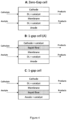
- the one or more electrolytic cells 1 are selected from zero-gap electrolytic cells, two-gap electrolytic cells, or one-gap electrolytic, which could be catholyte-free one-gap electrolytic cells.
- the one or more electrolytic cells are zero-gap electrolytic cells, such as membrane electrode assembly (MEA).
- MEA membrane electrode assembly
- the electrolytic cell is a zero-gap electrolytic cell (figure 2A) or a one-gap electrolytic cell (figure 2C and figure 2D), then the cathode catalyst layer is in contact with the ion-exchange membrane.
- the electrolytic cell is a zero-gap electrolytic cell (figure 2A) or a one-gap electrolytic cell (figure 2A) then the anode catalyst layer is in contact with the ion-exchange membrane.
- the electrolytic cell is a two-gap electrolytic cell (figure 2E)
- none of the cathode catalyst layer and anode catalyst layer is in contact with the ion-exchange membrane. This is due to the presence of both a catholyte and an anolyte.
- DL is for diffusion layer, which is a porous media which enable uniform distribution of reactive liquids of gases on the surface of the electrodes and transports of electrons.
- the zero-gap cell and the one-gap cell comprise at least one diffusion layer as illustrated on Figure 4 .
- Suitable materials for the diffusion layer are known to the person skilled in the art.
- the diffusion layer is a conductive material.
- the diffusion layer is a composite material comprising polytetrafluoroethylene (PTFE) and a conductive material such as carbon particles.
- the anode catalyst and the cathode catalyst may be any suitable catalyst known from the art.
- the anode catalyst and the cathode catalyst can be the same or different.
- the anode catalyst and/or the cathode catalyst are or comprise one or more transition metal-based catalysts comprising ruthenium, rhodium, palladium, osmium, iridium, platinum, titanium, cobalt, iron, nickel, niobium, molybdenum, alloys of titanium, alloys of cobalt, alloys of iron, alloys of nickel, alloys of niobium, alloys of molybdenum, oxides of ruthenium, oxides of rhodium, oxides of palladium, oxides of osmium, oxides of iridium, and oxides of platinum and any mixtures thereof.
- transition metal-based catalysts comprising ruthenium, rhodium, palladium, osmium, iridium, platinum, titanium, cobalt, iron, nickel, niobium, molybdenum, alloys of titanium, alloys of cobalt, alloys of iron, alloys of nickel, alloys
- the anode catalyst comprises platinum; with preference the anode catalyst comprises at least 0.5 wt.% of platinum based on the total weight of the anode catalyst.
- platinum losses could occur due to dissolution and poisoning ( Kyu Taek Cho, Michael C. Tucker, Adam Z. Weber, Energy Technology, Volume 4, Issue 6, 2016, Pages 655-678 )
- DSA ® brand anode catalysts produced by De Nora company could be applied.
- This type of anode uses mixed metal oxide (MMO) coating which allows a long and stable operation.
- MMO mixed metal oxide
- Lead Dioxide Titanium Electrode Ti/PbO 2
- the lead dioxide coating on titanium substrate has strong corrosion resistance and suitable for the media.
- anodes could be further modified by doping Ce or Bi metals to the anode catalyst using the techniques known in the art ( Pengfei Xu, Xiaohong He, Junwei Mao and Yongming Tang, Journal of The Electrochemical Society, Volume 166, Number 13, 2019, 638 ).
- the cathode catalyst comprises platinum; with preference the cathode catalyst comprises 0.5 wt.% of platinum based on the total weight of the cathode catalyst.
- the ion exchange membrane is a cation-exchange membrane (CEM), preferably a proton-exchange membrane (PEM). Both types of membranes are well-known by the person skilled in the art.
- Typical cation exchange membranes include proton conducting membranes, such as the perfluorosulfonic acid polymer available under the trade designation Nafion from E. I. du Pont de Nemours and Company (DuPont) of Wilmington, Del.
- a proton-exchange membrane, or polymer-electrolyte membrane (PEM) is a semipermeable membrane generally made from ionomers and designed to conduct protons while acting as an electronic insulator and reactant barrier, e.g. to oxygen and hydrogen gas.
- PEM membranes is Aquivion membranes developed by Solvay company.
- the cation-exchange membrane can further comprise an ionomer, more particularly an ionomer comprising fluoropolymer having one or more sulfonic acid groups or one or more pendant sulfonic acid groups.
- the cation-exchange membrane can comprise one or more layers, wherein the layer or at least one of the layers comprises an ionomer, more particularly an ionomer comprising fluoropolymer having one or more sulfonic acid groups or one or more pendant sulfonic acid groups.
- the ionomer comprises a perfluorinated sulfonic acid ionomer.
- said perfluorinated sulfonic acid ionomer comprises sulfonated tetrafluoroethylene based fluoropolymer-copolymer (such as Nafion ® or 1,1,2,2-Tetrafluoroethene;1,1,2,2-tetrafluoro-2-[1,1,1,2,3,3-hexafluoro-3-(1,2,2-trifluoroethenoxy)propan-2-yl]oxyethanesulfonic acid), SSC, Aciplex, Flemion, 3M-perfluorinated sulfonic acid ionomer, Aquivion, an ionene, or a combination thereof.
- the ion-exchange membrane is a proton exchange membrane comprising one or more layers, wherein the layer or at least one of the layers comprises an ionomer comprising a fluoropolymer having one or more pendant sulfonic acid groups.
- step b) providing a first input flow 101 at the anode side of the one or more electrolytic cells 1 that is or comprises a hydrogen bromide aqueous solution, and a second input flow 102 at the cathode side of the one or more electrolytic cells 1 that is or comprises water or an aqueous solution of one or more mineral acids
- the first input flow 101 provided at the anode side is or comprises a hydrogen bromide aqueous solution 101.
- hydrogen bromide is present in the hydrogen bromide aqueous solution at a content of at least 15 wt.% of HBr based on the total weight of the hydrogen bromide aqueous solution; preferably at least 25 wt.%; more preferably at least 30 wt.%; even more preferably at least 45 wt.%.
- hydrogen bromide is present in the hydrogen bromide aqueous solution at a content of at most 48.3 wt.% at 20 °C; and forms a constant-boiling azeotrope mixture.
- hydrogen bromide is present in the hydrogen bromide aqueous solution at a content ranging from 10 to 48.3 wt.% of HBr based on the total weight of the hydrogen bromide aqueous solution; preferably ranging from 15 to 47.6 wt.%; more preferably ranging from 17 to 45 wt.%; even more preferably ranging from 19 to 42 wt.% or from 20 to 40 wt.% or from 21 wt.% to 39 wt.% or from 22 wt.% to 48.3 wt.%.
- the first input flow 101 i.e ., the hydrogen bromide aqueous solution
- the first input flow 101 is metal-free.
- the second input flow 102 is provided at the cathode side and is or comprises water or an aqueous solution of one or more mineral acids.
- aqueous solution of one or more mineral acids serves as a source of protons.
- said aqueous solution has a pH of 0.1-5.
- the aqueous solution of the one or more mineral acids comprises one or more selected from hydrochloric acid (HCl), nitric acid (HNOs), phosphoric acid (H 3 PO 4 ), sulfuric acid (H 2 SO 4 ), boric acid (H 3 BO 3 ), hydrofluoric acid (HF), hydrobromic acid (HBr), perchloric acid (HClO 4 ), hydroiodic acid (HI), or any mixture thereof.
- the aqueous solution of the one or more mineral acids comprises hydrobromic acid, sulfuric acid, nitric acid, or mixture thereof, more preferably hydrobromic acid.
- the second input flow 102 is a lean hydrogen bromide aqueous solution at a content of less than 35 wt.%. More preferably the lean hydrogen bromide aqueous solution has a content of less than 25 wt.%.
- the first and/or the second input flow have liquid minute space velocity ranging from 0.1 to 20; preferably ranging from 0.2 to 2.
- the liquid minute space velocity (LMSV) is V1/V2, where V1 [L/min] - flow, V2 - volume of half-cell (between to electrode and membrane) wherein the LMSV is normalised.
- the first input flow 101 is obtained by mixing an aqueous solution with a gaseous phase comprising the bromide.
- the mixing of the aqueous solution with the gaseous phase comprising the bromide is a stripping process performed in an absorber.
- the gaseous phase comprising bromide can be pure HBr vapour, HBr azeotrope vapour or any gas stream comprising HBr.
- the gaseous phase comprising bromide is free of basic compounds.
- Operating the one or more electrolytic cells 1 comprises passing a current between the anode and the cathode.
- the electrolysis conditions comprise an anode current density of at least 0.5 kA/m 2 ; preferably, at least 0.6 kA/m 2 or 4.5 kA/m 2 ; more preferably, at least 1 kA/m 2 or 1.5 kA/m 2 ; even more preferably at least 2.0 kA/m 2 and most preferably at least 2.2 kA/m 2 or at least 2.5 kA/m 2 .
- the electrolysis conditions comprise an anode current density ranging from 0.5 to 10.0 kA/m 2 ; preferably, from 0.6 to 9.0 kA/m 2 ; more preferably, from 1 to 8.5 kA/m 2 ; even more preferably from 1.5 to 8.0 kA/m 2 and most preferably from 2 to 7.8 kA/m 2 or from 2.2 to 7.5 kA/m 2 .
- the electrolysis conditions comprise a voltage of at least 0.9 V or at least 1.0 V; preferably at least 1.1V or at least 1.2 V,
- the electrolysis conditions comprise a voltage ranging from 0.9 V to 10.0 V or from 1.0 V to 10.0 V; preferably from 1.1V to 9.5 V, more preferably from 1.2 V to 9.0 V.
- the electrolysis conditions comprising high voltage and high current density ensure maximum HBr conversion (>50%) per pass and the formation of a two-phase system as an effluent.
- the electrolysis conditions comprise a temperature of the solution during electrolysis that is ranging from 20 to 100°C; preferably from 40 to 95°C; more preferably from 50 to 90°C; and even more preferably from 60 to 85°C.
- the temperature of the solution during electrolysis is ranging from 20 to 100°C; preferably from 60 to 85°C.
- the liquid effluent 201 comprises bromine, water and and possibly unreacted hydrogen bromide.
- step d) further comprises recovering a gaseous effluent 202 comprising hydrogen at the cathode side.
- step d) of recovering a liquid effluent from the anode chamber comprises cooling the liquid effluent at a temperature ranging from 10 to 40°C before the separating step e). This can be done using one or more heat exchangers.
- the separation in step e) may be performed by distillation or decantation in the separation unit 2.
- the separation unit 2 may be any known in the art.
- the separation unit 2 is a separation funnel or a decanter.
- the separation unit 2 is a decanter.
- step e) further comprises a decanting step e1) comprising passing the liquid effluent comprising bromine in the decanter to obtain the first liquid phase 301 comprising bromine and the second liquid phase 302 comprising unreacted hydrogen bromide.
- the first liquid phase 301 comprising bromine may be recovered and stored for further use.
- the second liquid phase 302 is sent to the concentration unit 3 in step g).
- the decanting step e1) is performed for a time sufficient to obtain a two phases separation.
- the decanting step e1) is performed during a time of at least 10 minutes; preferably during a time ranging from 10 minutes to 1 hour.
- the decanting step e) is performed at a pressure of at least 0.12 MPa to avoid vapour formation so that the bromine is kept in a liquid phase.
- the decanting step e1) is performed at a pressure of at least 0.15 MPa; preferably at least 0.20 MPa; and/or at most 0.5 MPa.
- step e) may further comprise step e2) drying the first liquid phase comprising bromine 301.
- the drying step is performed in any drying unit known in the art.
- the drying step e2) is performed in a drying unit using a molecular sieve.
- the final product is or comprises dry bromine.
- Said molecular sieves could be, for instance 3A, which is a commercial product used for drying.
- step g) concentrating the second liquid phase to obtain a third liquid phase comprising bromide, wherein the concentration of the bromide in the second liquid phase 302 is lower than the concentration of the bromide in the third liquid phase 401.
- the bromide is present in the second liquid phase 302 at a content of less than 30 wt.% of HBr based on the total weight of the hydrogen bromide aqueous solution; preferably less than 20 wt.%; more preferably ranging from 10 wt.%; even more preferably less than 2 wt.%.
- the bromide is present in the third liquid phase 401 at a content ranging from 10 to 68.85 wt.% of HBr based on the total weight of the hydrogen bromide aqueous solution; preferably ranging from 15 to 60 wt.%; more preferably ranging from 17 to 55 wt.%; even more preferably ranging from 19 to 50 wt.% or from 20 to 50 wt.% or from 21 wt.% to 49.85 wt.% or from 22 wt.% to 48.85 wt.%.
- the concentration in step g) may be performed in a concentration unit 3 by removing part of the water or by adding bromide; for example, hydrogen bromide.
- the concentration is performed by distillation or by mixing the second liquid phase 302 with a gaseous phase comprising bromide.
- Concentration unit 3 may be any known in the art.
- the concentration unit is a distillation column or an absorber.
- step g) is performed by mixing the second liquid phase 302 with a gaseous phase comprising bromide in the same absorber as used for obtaining the first input flow 101.
- the third stream 401 is taken over in the first input flow 101 and fed to the electrolytical cell 1.
- the second liquid phase 302 which comprises unreacted hydrogen bromide, is taken over in the second input flow 102.
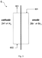
- a gaseous stream 501 comprising HBr and/or HBr azeotrope vapour is provided to an absorber 5.
- an effluent with lean HBr aqueous solution or water, and which is liquid flows through an absorber 5 and contacts a gaseous stream 501.
- the resulting liquid effluent is an aqueous stream enriched in HBr, which is further sent as a first input flow 601 to the anode side of the electrolytical cell 6.
- a second input flow 602 comprising water or an aqueous solution of one or more mineral acids, such as hydrogen bromide, is sent to the cathode side of the electrolytical cell 6.
- a liquid effluent 701 comprising bromine (Br 2 ), and also water and unreacted (residual) HBr, is removed from the anode side and is directed to a separation unit 7, to obtain a first liquid phase 801 containing Br 2 substantially free of water and a second liquid phase 802 containing water and the unreacted HBr.
- the second liquid phase 802 is redirected to the cathode side of the electrolytical cell 6, for example directly and/or via the second input flow 602, and may absorb potential HBr formed due to crossover through the membrane.
- the lean HBr stream 901 exiting the cathode side is then redirected to the absorber 5, optionally with a water makeup, and serves as the liquid effluent with lean HBr aqueous solution or water, which is liquid, and which is flowed through the absorber 5.
- hydrogen is produced at the cathode side of the electrolytical cell 6 and recovered as a hydrogen stream 702.
- the disclosure also provides an installation for bromine production according to the process of the first aspect; wherein the installation comprises one or more electrolytic cells 1, 6 comprising an anode, a cathode, an anode chamber, a cathode chamber and a solid polymer electrolyte membrane separating the anode chamber from the cathode chamber; at least a separating unit 2, 7, at least a concentration unit 3, 5, and means to convey the liquid effluent exiting the anodic chamber of the one or more electrolytic cells to the separating unit, means to convey the second liquid phase from the separating unit to the concentration unit and optionally means to convey the third liquid phase to the first input flow.
- the installation comprises one or more electrolytic cells 1, 6 comprising an anode, a cathode, an anode chamber, a cathode chamber and a solid polymer electrolyte membrane separating the anode chamber from the cathode chamber; at least a separating unit 2, 7, at least a concentration unit 3, 5, and means to convey the liquid
- the separating unit is a decanter or a distillation column.
- the concentration unit is an absorber.
- the one or more electrolytic cells are selected from zero-gap electrolytic cells, two-gap electrolytic cells, catholyte-containing one-gap electrolytic cells and catholyte-free one-gap electrolytic cells; preferably the one or more electrolytic cells are zero-gap electrolytic cells, such as membrane electrode assembly (MEA).
- MEA membrane electrode assembly
- a symmetric zero-gap custom-made electrolytic cell with an active area of 40 cm 2 was assembled to perform the electrolysis tests.
- the cell comprises titanium end plates, carbon loaded polymer channel plates, gas diffusion electrodes made of carbon cloth with Pt loading (0.5 wt.%) and a reinforced Nation TM N324 membrane.
- the National TM N324 is a perfluorosulfonic acid (PFSA) cation exchange membrane, combining outstanding chemical resistance with a strong polytetrafluoroethylene (PTFE) fibre reinforcement.
- PFSA perfluorosulfonic acid
- PTFE polytetrafluoroethylene
- the cell was put on a heated shelf to maintain the operating temperature at 80 °C and liquid effluents were passed through a heat exchanger at 20 °C to avoid evaporation.
- the HBr azeotrope (cca. 48 wt.% of HBr in water) was fed to the anode side using a teflonized peristaltic pump at a flow rate of 20 mL/min. To avoid membrane drying, the cathode side was fed with a stream of 2 wt.% of HBr in water at a flow rate of 10 mL/min.
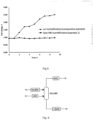
- a stable operation of the cell was achieved with an operating voltage of about 1V, as shown in Figure 5 .
- a symmetric zero-gap custom made electrolytic cell with an active area of 40 cm 2 was assembled to perform the electrolysis tests.
- the cell comprises titanium end plates, carbon loaded polymer channel plates, gas diffusion electrodes made of carbon cloth with Pt loading (0.5 wt.%) and a reinforced Nation TM N324 membrane.
- the cell was put on a heated shelf to maintain the operating temperature at 80 °C and liquid effluents were passed through a heat exchanger at 20 °C to avoid evaporation.
- the HBr azeotrope (cca. 48 wt.% of HBr in water) was fed to the anode side using a teflonized peristaltic pump at a flow rate of 20 mL/min.
- the cathode side was flushed with dry nitrogen, 60 mL/min.
- Gradual voltage increase indicated instability of cell operation due to drying and loss of conductivity of the membrane, as shown in Figure 5 .
- the treated gas flow comprised dry HBr (0.4 kg/hr) and N 2 (0.2 kg/hr) and was fed on the bottom stage of the column (see figure 6 ).
- Liquid absorbent comprised pure water (1 kg/hr) and was fed on the top stage to have counter-current flow.
- the system operated at 2 barG. Exothermic absorption occurred leading to complete removal of HBr from the inlet stream.
- the outlets of the column comprise two streams:
- Results are provided in the below table: Stream Name Units GAS HBr LIQUID WATER Temperature C 94 25 130 25 Pressure bar 2 2 2 2 H 2 O kg/hr 0.05 0.00 0.86 1.00 HBr kg/hr 0.00 0.40 0.00 0.00 H 3 O + kg/hr 0.00 0.00 0.09 0.00 Br kg/hr 0.00 0.00 0.39 0.00 N 2 kg/hr 0.20 0.20 0.00 0.00
Landscapes
- Chemical & Material Sciences (AREA)
- Organic Chemistry (AREA)
- Engineering & Computer Science (AREA)
- Chemical Kinetics & Catalysis (AREA)
- Electrochemistry (AREA)
- Materials Engineering (AREA)
- Metallurgy (AREA)
- Inorganic Chemistry (AREA)
- Electrolytic Production Of Non-Metals, Compounds, Apparatuses Therefor (AREA)
Priority Applications (3)
| Application Number | Priority Date | Filing Date | Title |
|---|---|---|---|
| EP23315211.5A EP4467516A1 (de) | 2023-05-24 | 2023-05-24 | Verfahren zur rückgewinnung von brom aus bromwasserstoffhaltigen strömen |
| PCT/EP2024/064420 WO2024240947A1 (en) | 2023-05-24 | 2024-05-24 | Process for production of sulfuric acid from a hydrogen sulfide |
| PCT/EP2024/064415 WO2024240945A1 (en) | 2023-05-24 | 2024-05-24 | Process for production of concentrated sulfuric acid |
Applications Claiming Priority (1)
| Application Number | Priority Date | Filing Date | Title |
|---|---|---|---|
| EP23315211.5A EP4467516A1 (de) | 2023-05-24 | 2023-05-24 | Verfahren zur rückgewinnung von brom aus bromwasserstoffhaltigen strömen |
Publications (1)
| Publication Number | Publication Date |
|---|---|
| EP4467516A1 true EP4467516A1 (de) | 2024-11-27 |
Family
ID=86861923
Family Applications (1)
| Application Number | Title | Priority Date | Filing Date |
|---|---|---|---|
| EP23315211.5A Withdrawn EP4467516A1 (de) | 2023-05-24 | 2023-05-24 | Verfahren zur rückgewinnung von brom aus bromwasserstoffhaltigen strömen |
Country Status (1)
| Country | Link |
|---|---|
| EP (1) | EP4467516A1 (de) |
Cited By (1)
| Publication number | Priority date | Publication date | Assignee | Title |
|---|---|---|---|---|
| CN120719303A (zh) * | 2025-08-29 | 2025-09-30 | 中国石油大学(华东) | 一种含溴废水电氧化处理系统及方法 |
Citations (6)
| Publication number | Priority date | Publication date | Assignee | Title |
|---|---|---|---|---|
| EP0476862A1 (de) * | 1990-09-04 | 1992-03-25 | Great Lakes Chemical Corporation | Elektrolytische Brom-Herstellung und ihre Verwendung bei der Rückgewinnung von Edelmetallen und Abwässerbehandlung |
| WO1994025643A1 (en) * | 1993-04-30 | 1994-11-10 | Great Lakes Chemical Corporation | Recovery of bromine and preparation of hypobromous acid from bromide solution |
| WO2006110780A2 (en) * | 2005-04-12 | 2006-10-19 | University Of South Carolina | Production of low temperature electrolytic hydrogen |
| CN102482083A (zh) | 2009-07-15 | 2012-05-30 | 马拉索恩科技有限责任公司 | 将溴化氢转化成单质溴 |
| US20180222776A1 (en) | 2013-03-15 | 2018-08-09 | Southern Methodist University | Method and Apparatus for Electrochemical Bromide Removal |
| CN113789525A (zh) | 2021-09-29 | 2021-12-14 | 山东海王化工股份有限公司 | 电解酸化溴化钠生产溴素的工艺方法 |
-
2023
- 2023-05-24 EP EP23315211.5A patent/EP4467516A1/de not_active Withdrawn
Patent Citations (7)
| Publication number | Priority date | Publication date | Assignee | Title |
|---|---|---|---|---|
| EP0476862A1 (de) * | 1990-09-04 | 1992-03-25 | Great Lakes Chemical Corporation | Elektrolytische Brom-Herstellung und ihre Verwendung bei der Rückgewinnung von Edelmetallen und Abwässerbehandlung |
| US5385650A (en) | 1991-11-12 | 1995-01-31 | Great Lakes Chemical Corporation | Recovery of bromine and preparation of hypobromous acid from bromide solution |
| WO1994025643A1 (en) * | 1993-04-30 | 1994-11-10 | Great Lakes Chemical Corporation | Recovery of bromine and preparation of hypobromous acid from bromide solution |
| WO2006110780A2 (en) * | 2005-04-12 | 2006-10-19 | University Of South Carolina | Production of low temperature electrolytic hydrogen |
| CN102482083A (zh) | 2009-07-15 | 2012-05-30 | 马拉索恩科技有限责任公司 | 将溴化氢转化成单质溴 |
| US20180222776A1 (en) | 2013-03-15 | 2018-08-09 | Southern Methodist University | Method and Apparatus for Electrochemical Bromide Removal |
| CN113789525A (zh) | 2021-09-29 | 2021-12-14 | 山东海王化工股份有限公司 | 电解酸化溴化钠生产溴素的工艺方法 |
Non-Patent Citations (2)
| Title |
|---|
| KYU TAEK CHOMICHAEL C. TUCKERADAM Z. WEBER, ENERGY TECHNOLOGY, vol. 4, no. 6, 2016, pages 655 - 678 |
| PENGFEI XUXIAOHONG HEJUNWEI MAOYONGMING TANG, JOURNAL OF THE ELECTROCHEMICAL SOCIETY, vol. 166, no. 13, 2019, pages 638 |
Cited By (1)
| Publication number | Priority date | Publication date | Assignee | Title |
|---|---|---|---|---|
| CN120719303A (zh) * | 2025-08-29 | 2025-09-30 | 中国石油大学(华东) | 一种含溴废水电氧化处理系统及方法 |
Similar Documents
| Publication | Publication Date | Title |
|---|---|---|
| US9574276B2 (en) | Production of low temperature electrolytic hydrogen | |
| CN104641019B (zh) | 用于卤素和一氧化碳电化学联合生产羰基化产物的方法和系统 | |
| EP0730675B1 (de) | Elektrochemische umwandlung von wasserfreien wasserstoffhaliden zu halogengas unter zuhilfenahme von kationtransportmembranen | |
| AU648076B2 (en) | Process for the production of chloric acid and perchloric acid | |
| Motupally et al. | Recycling chlorine from hydrogen chloride: a new and economical electrolytic process | |
| WO2003010360A1 (en) | Electrochemical synthesis of hydrogen peroxide | |
| US6685818B2 (en) | Process for the electrochemical preparation of hydrogen peroxide | |
| WO2017118712A1 (en) | Method and system for electrochemical reduction of carbon dioxide employing a gas diffusion anode | |
| WO1996034997A1 (en) | Electrochemical cell and process for splitting a sulfate solution and producing a hydroxide solution, sulfuric acid and a halogen gas | |
| WO2021195746A1 (en) | Electrosynthesis of oxiranes | |
| WO2002002846A2 (en) | Electrochemical cell | |
| JP3493242B2 (ja) | 硝酸塩の電気化学的回収方法及び装置 | |
| EP4467686A1 (de) | Verfahren zur herstellung von brom | |
| EP0870076A1 (de) | Herstellung von carbonylhalogenid | |
| Inaba et al. | Application of the Solid Polymer Electrolyte Method to Organic Electrochemistry: XIV. Effects of Solvents on the Electroreduction of Nitrobenzene on Cu, Pt‐Nafion | |
| WO2025149572A1 (en) | PROCESS FOR BROMINE SEPARATION FROM AQUEOUS SOLUTIONS OF HBr | |
| EP4467517A1 (de) | Verfahren zur herstellung von schwefelsäure aus h2s | |
| US9273405B1 (en) | Electrolysis device for chlorine production | |
| CA2219922A1 (en) | Electrochemical conversion of anhydrous hydrogen halide to halogen gas using a cation-transporting membrane | |
| MXPA97008397A (en) | Electrochemical conversion of hydrogenoanhydro halide to halogen gas using a transportation member cation | |
| WO2024240947A1 (en) | Process for production of sulfuric acid from a hydrogen sulfide | |
| EP4602196B1 (de) | Co2-elektroreduktion zu mehrkohlenstoffprodukten in sauren bedingungen in verbindung mit co2-regeneration aus carbonat | |
| EP4646503A1 (de) | Elektrochemische reduktion von kohlendioxid zu ameisensäure | |
| CN119640328A (zh) | 电化学合成氨的方法及所用的聚合物固体电解质 |
Legal Events
| Date | Code | Title | Description |
|---|---|---|---|
| STAA | Information on the status of an ep patent application or granted ep patent |
Free format text: STATUS: UNKNOWN |
|
| PUAI | Public reference made under article 153(3) epc to a published international application that has entered the european phase |
Free format text: ORIGINAL CODE: 0009012 |
|
| STAA | Information on the status of an ep patent application or granted ep patent |
Free format text: STATUS: THE APPLICATION HAS BEEN PUBLISHED |
|
| AK | Designated contracting states |
Kind code of ref document: A1 Designated state(s): AL AT BE BG CH CY CZ DE DK EE ES FI FR GB GR HR HU IE IS IT LI LT LU LV MC ME MK MT NL NO PL PT RO RS SE SI SK SM TR |
|
| STAA | Information on the status of an ep patent application or granted ep patent |
Free format text: STATUS: THE APPLICATION IS DEEMED TO BE WITHDRAWN |
|
| 18D | Application deemed to be withdrawn |
Effective date: 20250528 |