EP4467482A1 - Closure capsule for closing a container - Google Patents
Closure capsule for closing a container Download PDFInfo
- Publication number
- EP4467482A1 EP4467482A1 EP24170341.2A EP24170341A EP4467482A1 EP 4467482 A1 EP4467482 A1 EP 4467482A1 EP 24170341 A EP24170341 A EP 24170341A EP 4467482 A1 EP4467482 A1 EP 4467482A1
- Authority
- EP
- European Patent Office
- Prior art keywords
- tamper
- lid
- capsule
- mouth
- container
- Prior art date
- Legal status (The legal status is an assumption and is not a legal conclusion. Google has not performed a legal analysis and makes no representation as to the accuracy of the status listed.)
- Granted
Links
Images




Classifications
-
- B—PERFORMING OPERATIONS; TRANSPORTING
- B65—CONVEYING; PACKING; STORING; HANDLING THIN OR FILAMENTARY MATERIAL
- B65D—CONTAINERS FOR STORAGE OR TRANSPORT OF ARTICLES OR MATERIALS, e.g. BAGS, BARRELS, BOTTLES, BOXES, CANS, CARTONS, CRATES, DRUMS, JARS, TANKS, HOPPERS, FORWARDING CONTAINERS; ACCESSORIES, CLOSURES, OR FITTINGS THEREFOR; PACKAGING ELEMENTS; PACKAGES
- B65D55/00—Accessories for container closures not otherwise provided for
- B65D55/16—Devices preventing loss of removable closure members
-
- B—PERFORMING OPERATIONS; TRANSPORTING
- B65—CONVEYING; PACKING; STORING; HANDLING THIN OR FILAMENTARY MATERIAL
- B65D—CONTAINERS FOR STORAGE OR TRANSPORT OF ARTICLES OR MATERIALS, e.g. BAGS, BARRELS, BOTTLES, BOXES, CANS, CARTONS, CRATES, DRUMS, JARS, TANKS, HOPPERS, FORWARDING CONTAINERS; ACCESSORIES, CLOSURES, OR FITTINGS THEREFOR; PACKAGING ELEMENTS; PACKAGES
- B65D51/00—Closures not otherwise provided for
- B65D51/24—Closures not otherwise provided for combined or co-operating with auxiliary devices for non-closing purposes
- B65D51/28—Closures not otherwise provided for combined or co-operating with auxiliary devices for non-closing purposes with auxiliary containers for additional articles or materials
- B65D51/2807—Closures not otherwise provided for combined or co-operating with auxiliary devices for non-closing purposes with auxiliary containers for additional articles or materials the closure presenting means for placing the additional articles or materials in contact with the main contents by acting on a part of the closure without removing the closure, e.g. by pushing down, pulling up, rotating or turning a part of the closure, or upon initial opening of the container
- B65D51/2814—Closures not otherwise provided for combined or co-operating with auxiliary devices for non-closing purposes with auxiliary containers for additional articles or materials the closure presenting means for placing the additional articles or materials in contact with the main contents by acting on a part of the closure without removing the closure, e.g. by pushing down, pulling up, rotating or turning a part of the closure, or upon initial opening of the container the additional article or materials being released by piercing, cutting or tearing an element enclosing it
- B65D51/2842—Closures not otherwise provided for combined or co-operating with auxiliary devices for non-closing purposes with auxiliary containers for additional articles or materials the closure presenting means for placing the additional articles or materials in contact with the main contents by acting on a part of the closure without removing the closure, e.g. by pushing down, pulling up, rotating or turning a part of the closure, or upon initial opening of the container the additional article or materials being released by piercing, cutting or tearing an element enclosing it said element being provided with a preformed weakened line
- B65D51/285—Closures not otherwise provided for combined or co-operating with auxiliary devices for non-closing purposes with auxiliary containers for additional articles or materials the closure presenting means for placing the additional articles or materials in contact with the main contents by acting on a part of the closure without removing the closure, e.g. by pushing down, pulling up, rotating or turning a part of the closure, or upon initial opening of the container the additional article or materials being released by piercing, cutting or tearing an element enclosing it said element being provided with a preformed weakened line ruptured by a sharp element, e.g. a cutter or a piercer
-
- B—PERFORMING OPERATIONS; TRANSPORTING
- B65—CONVEYING; PACKING; STORING; HANDLING THIN OR FILAMENTARY MATERIAL
- B65D—CONTAINERS FOR STORAGE OR TRANSPORT OF ARTICLES OR MATERIALS, e.g. BAGS, BARRELS, BOTTLES, BOXES, CANS, CARTONS, CRATES, DRUMS, JARS, TANKS, HOPPERS, FORWARDING CONTAINERS; ACCESSORIES, CLOSURES, OR FITTINGS THEREFOR; PACKAGING ELEMENTS; PACKAGES
- B65D2401/00—Tamper-indicating means
- B65D2401/15—Tearable part of the closure
- B65D2401/20—Frangible elements completely enclosed in closure skirt
-
- B—PERFORMING OPERATIONS; TRANSPORTING
- B65—CONVEYING; PACKING; STORING; HANDLING THIN OR FILAMENTARY MATERIAL
- B65D—CONTAINERS FOR STORAGE OR TRANSPORT OF ARTICLES OR MATERIALS, e.g. BAGS, BARRELS, BOTTLES, BOXES, CANS, CARTONS, CRATES, DRUMS, JARS, TANKS, HOPPERS, FORWARDING CONTAINERS; ACCESSORIES, CLOSURES, OR FITTINGS THEREFOR; PACKAGING ELEMENTS; PACKAGES
- B65D2401/00—Tamper-indicating means
- B65D2401/15—Tearable part of the closure
- B65D2401/30—Tamper-ring remaining connected to closure after initial removal
Definitions
- the present invention relates to a closure capsule for closing a container typically used for pharmaceutical or nutraceutical substances.
- Closure capsules provided with a tamper-evident ring are known and they are known in the technical field as "tamper-evident capsules".
- Such capsules thus comprise a lid applicable to the neck of a container and a lower strip connected to the lid by means of frangible connection bridges.
- the interface between the lid and the strip thus defines a zone of facilitated fracture when the user moves the lid. In this way the user has proof that the capsule has already been used and cannot be confused with a new one.
- An example is shown by patent EP3436365 .
- Object of the present invention is to make available a closure capsule that, once opened to allow access to the product contained in the container, does not have easily removable and accidentally ingestable parts.
- reference number 1 denotes a closure capsule for closing a container.
- the closure capsule 1 comprises a lid 2 positionable on a mouth of the container.
- the capsule 1 also comprises a first tamper-evident ring 3.
- the first tamper-evident ring 3 defines a tamper-evident element.
- the capsule 1 comprises a second tamper-evident ring 4 interposed between the lid 2 and the first tamper-evident ring 3.
- the second tamper-evident ring 4 defines a tamper-evident element.
- connection means 5 may comprise frangible connection means 50.
- frangible connection means 50 are yielding bridges. They allow a programmed separation along a pre-fracture line.
- the connection means 5 may comprise stable connection means 51.
- the stable connection means 51 is intended to maintain the connection between the first and the second tamper-evident ring 3, 4 even in a configuration in which the frangible connection means 50 has yielded.
- the stable connection means 51 comprises one or more connections that are more robust than the yielding bridges of the means 50 and therefore is not affected by the pre-fracture line.
- the first tamper-evident ring 3 comprises a zone 30 of facilitated fracture intended to separate two flaps 31, 32 of the first ring 3 itself.
- This zone 30 of facilitated fracture affects a section of the annular extension (typically circumferential) of the first tamper-evident ring 3.
- the zone 30 of facilitated fracture thus makes it possible to obtain a first split tamper-evident ring 2 (compare figures 1 and 2 in this regard).
- the second tamper-evident ring 4 in turn comprises:
- the strip 42 prevents separation of the lid 2 from the annular base 41. As exemplified in the appended figures, it allows the distancing or approach, but not separation thereof.
- the lid 2 and the annular base 41 therefore define a piece that extends seamlessly. And it is precisely the strip 42 that connects the lid 2 and the annular base 41.
- the strip 42 is flexible.
- the strip 42 has a predominant longitudinal extension.
- the annular base 41 comprises a first projection 43 towards the lid 2 from which the strip 42 starts.
- the first projection 43 always remains connected (suitably it is in a single monolithic body) both to the annular base 41 and to the strip 42.
- the lid 2 comprises a second projection 44 towards the annular base 41 where the strip 42 ends.
- the second projection 44 always remains connected (suitably it is in a single monolithic body) both to the lid 2 and to the strip 42.
- the lid 2 and the second tamper-evident ring 4 are mutually connected both with yielding portions 43 and with at least one zone (which by way of example is indicated by reference 44 in the appended figures and to which reference was made above as second projection 44) that prevents complete separation thereof.
- the yielding portions 43 affect opposing portions of the strip 42 and of the lid 2.
- the first and the second tamper-evident ring 3, 4 are fractured by rotating the lid 2 constrained to the container in mutually opposite directions.
- the capsule 1 comprises a cap 6 intended to occlude the mouth of the container.
- the cap 6 comprises a frangible bottom 60.
- the frangible bottom 60 comprises a pre-scoring or a zone of facilitated breakage.
- the cap 6 is removable from the container to allow the product to be dispensed.
- the capsule 1 also comprises a cutter 7 intended for opening the frangible bottom 60.
- the cutter 7 is movable between:
- the cutter 7 may comprise an internally hollow stem 71.
- the cutter 7 comprises at one end a cutting edge 72 used for opening the frangible bottom 60.
- the lid 2 surmounts the cutter 7. It performs a protective function by preventing access from the outside.
- the lid 2 is also movable between a configuration close to the annular base 41 (see for example figures 1 or 4 or 5 ) and a configuration distanced from the annular base 41 (see for example figures 2 or 3 or 6 ).
- the strip 42 is deformable and mutually connects the lid 2 and the annular base 41 both in the close configuration and in the distanced configuration.
- at least a section of the strip 42, in the distanced configuration provides for a spiral-shaped extension (see for example figure 2 ).
- the strip 42 has a length extension comprised between half a turn and a full turn.
- the strip 42 has a course according to an arc of circumference (see for example figure 1 ) and is suitably parallel to a plane. In the close configuration the strip 42 extends parallel to the annular base 41.
- the passage from the close configuration to the distanced configuration is associated with the final configuration of the cutter 7. Therefore, the passage from the close configuration to the distanced configuration (and vice versa) takes place with the cutter 7 in the final configuration.
- the present invention also relates to a dispenser 10 for a product.
- the dispenser 10 comprises a container 8.
- the container 8 comprises a product dispensing mouth 80.
- the dispenser 10 also comprises a capsule 1 applied to said mouth 80.
- mouth 80 is intended to mean the neck of the container 8.
- the capsule 1 has one or more of the characteristics described hereinabove.
- the container 8, along the mouth 80, comprises anti-extraction abutment means 81 intended to interact with the capsule 1.
- the abutment means 81 comprises/coincides with a projection 810 protruding towards the outside of the mouth 80.
- said projection 810 is annular and surrounds the mouth 80.
- the projection 810 extends circumferentially and protrudes radially outward.
- the first tamper-evident ring 3 is engaged with the abutment means 81 (see figure 4 ).
- the second tamper-evident ring 4 is not directly engaged with the container.
- the annular base 41 is engaged with the abutment means 81 (see for example figure 5 ).
- the second tamper-evident ring 4 is not directly engaged with the container.
- the first and the second tamper-evident ring 3, 4 respectively comprise a first and a second protuberance 36, 46 protruding towards the mouth 80.
- the abutment means 81 When the first tamper-evident ring 3 is engaged with the abutment means 81, the abutment means 81 is intended to abut the protuberance 36 of the first tamper-evident ring 3 preventing extraction thereof. Similarly, when the second tamper-evident ring 4 is engaged with the abutment means 81, the abutment means 81 is intended to abut the protuberance 46 of the second tamper-evident ring 4 preventing extraction thereof. In the second configuration, the first tamper-evident ring 3 is broken along the perimeter extension (preferably circumferential); this occurs in the fracture zone 30 (see for example figure 2 or 5 ).
- frangible connection means 50 referred to above is broken; this allows a partial separation of the first tamper-evident ring 3 from the second tamper-evident ring 4. Also in the second configuration (see for example figures 2 and 5 ) the first and the second tamper-evident ring 3, 4 remain mutually connected by the stable connection means 51.
- the lid 2, the first tamper-evident ring 3, the second tamper-evident ring 4 define a monolithic single body.
- the lid 2, the first tamper-evident ring 3, the second tamper-evident ring 4 define a monolithic single body (even if partially fractured the lid 2, the first tamper-evident ring 3, the second tamper-evident ring 4 remain united in a monolithic single body).
- the first configuration is associated with the initial configuration of the cutter 7.
- the second configuration is associated with the final configuration of the cutter 7.
- the present invention also relates to a method for operating (in particular opening) a closure capsule 1 for closing a mouth 80 of a container 8.
- the capsule 1 suitably has one or more of the characteristics described above.
- the capsule 1 comprises a lid 2, a first tamper-evident ring 3, a second tamper-evident ring 4 interposed between the lid 2 and the first tamper-evident ring 3.
- the second tamper-evident ring 4 in turn comprises an annular base 41 constrained to the first ring 3 and a strip 42 connecting the annular base 41 and the lid 2.
- the strip 42 prevents separation of the lid 2 from the annular base 41.
- the method comprises the step of screwing the lid 2 along the mouth 80 of the container 8 (or more generally of moving the lid 2 towards the container 8; it could take place with a push even without threading). See for example the passage from figure 1 to figure 2 or from figure 4 to figure 5 .
- This step causes breaking the first tamper-evident ring 3 previously engaged with the anti-extraction abutment means 81 placed along the mouth 80.
- the step of screwing the lid 2 to the mouth 80 of the container comprises in fact the sub-step of shifting the first tamper-evident ring 3 from a position in which it surrounds the mouth 80, to a position in which it surrounds a part of the side 82 of the container 8.
- the side 82 has a greater cross-section than the mouth 80.
- the step of screwing the lid 2 along the mouth 80 of the container 8 also provides for the engagement of the annular base 41 of the second tamper-evident ring 4 with the anti-extraction abutment means 81.
- This provides that the annular base 41 steps over at least a part of the anti-extraction abutment means 81.
- the annular base 41 remains interposed between the abutment means 81 and the side 82 of the container. This prevents extraction thereof through the mouth 80.
- the step of screwing the lid 2 along the mouth 80 also provides for constraining by extraction the cap 6 to the lid 2. In fact, during screwing a projection 45 towards the outside of the cap 4 steps over a projection 21 towards the inside of the lid 2.
- the capsule 1 comprises:
- the step of screwing the lid 2 comprises the step of pushing with said lid 2 the cutter 7 against the frangible bottom 60, causing the opening of the frangible bottom 60 and the dispensing of the first substance into the container 8 (see passage from figure 4 to figure 5 ).
- the method also comprises the step of unscrewing the lid 2 from the mouth 80 keeping the annular base 41 constrained to the abutment means 81 and deforming the strip 42 to remove the lid 2 from a position in which it occludes a product dispensing opening 800 located at one end of the mouth 80.
- the strip 42 will in fact have one end that remains constrained to the annular base 41 (which remains retained in position by the abutment means 81) and the other end that remains constrained to the lid 2.
- the annular base 41 retained by the abutment means 81 is free to rotate around the mouth 80.
- the lid 2 drags into extraction also the cap 6, which in turn drags the cutter 7 (see passage from figure 5 to figure 6 ).
- the present invention achieves important advantages.
Landscapes
- Engineering & Computer Science (AREA)
- Mechanical Engineering (AREA)
- Closures For Containers (AREA)
Abstract
Description
- The present invention relates to a closure capsule for closing a container typically used for pharmaceutical or nutraceutical substances. Closure capsules provided with a tamper-evident ring are known and they are known in the technical field as "tamper-evident capsules".
- Such capsules thus comprise a lid applicable to the neck of a container and a lower strip connected to the lid by means of frangible connection bridges. The interface between the lid and the strip thus defines a zone of facilitated fracture when the user moves the lid. In this way the user has proof that the capsule has already been used and cannot be confused with a new one. An example is shown by patent
EP3436365 . - Object of the present invention is to make available a closure capsule that, once opened to allow access to the product contained in the container, does not have easily removable and accidentally ingestable parts.
- The stated technical task and specified objects are substantially achieved by a closure capsule comprising the technical features set forth in one or more of the appended claims.
- Further features and advantages of the present invention will become more apparent from the indicative, and hence non-limiting, description of a preferred, but not exclusive, embodiment of a closure capsule as illustrated in the appended drawings, in which:
-
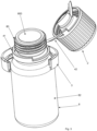
figures 1-3 show in perspective view a succession of steps for opening the capsule; -
figures 4-6 show in cross-section a succession of steps for opening the capsule. - In the appended figures, reference number 1 denotes a closure capsule for closing a container.
- The closure capsule 1 comprises a
lid 2 positionable on a mouth of the container. - The capsule 1 also comprises a first tamper-
evident ring 3. The first tamper-evident ring 3 defines a tamper-evident element. - The capsule 1 comprises a second tamper-
evident ring 4 interposed between thelid 2 and the first tamper-evident ring 3. The second tamper-evident ring 4 defines a tamper-evident element. - The first and the second tamper-
evident ring evident ring means 50 and therefore is not affected by the pre-fracture line. Suitably, the first tamper-evident ring 3 comprises azone 30 of facilitated fracture intended to separate twoflaps first ring 3 itself. Thiszone 30 of facilitated fracture affects a section of the annular extension (typically circumferential) of the first tamper-evident ring 3. At a section of the circumferential extension of thefirst ring 3 there are therefore twoopposing flaps zone 30 of facilitated fracture that is located in this section. Thezone 30 of facilitated fracture thus makes it possible to obtain a first split tamper-evident ring 2 (comparefigures 1 and2 in this regard). - The second tamper-
evident ring 4 in turn comprises: - an
annular base 41 constrained to the first tamper-evident ring 3; - a
strip 42 connecting theannular base 41 and thelid 2. - The
strip 42 prevents separation of thelid 2 from theannular base 41. As exemplified in the appended figures, it allows the distancing or approach, but not separation thereof. Thelid 2 and theannular base 41 therefore define a piece that extends seamlessly. And it is precisely thestrip 42 that connects thelid 2 and theannular base 41. Thestrip 42 is flexible. - Suitably, the
strip 42 has a predominant longitudinal extension. - The
annular base 41 comprises afirst projection 43 towards thelid 2 from which thestrip 42 starts. Thefirst projection 43 always remains connected (suitably it is in a single monolithic body) both to theannular base 41 and to thestrip 42. Thelid 2 comprises asecond projection 44 towards theannular base 41 where thestrip 42 ends. Thesecond projection 44 always remains connected (suitably it is in a single monolithic body) both to thelid 2 and to thestrip 42. - Suitably, the
lid 2 and the second tamper-evident ring 4 are mutually connected both with yieldingportions 43 and with at least one zone (which by way of example is indicated byreference 44 in the appended figures and to which reference was made above as second projection 44) that prevents complete separation thereof. - Suitably, the yielding
portions 43 affect opposing portions of thestrip 42 and of thelid 2. - The first and the second tamper-
evident ring lid 2 constrained to the container in mutually opposite directions. - The capsule 1 comprises a
cap 6 intended to occlude the mouth of the container. Thecap 6 comprises afrangible bottom 60. For example, thefrangible bottom 60 comprises a pre-scoring or a zone of facilitated breakage. Thecap 6 is removable from the container to allow the product to be dispensed. - The capsule 1 also comprises a
cutter 7 intended for opening thefrangible bottom 60. Thecutter 7 is movable between: - an initial configuration in which it defines, in combination at least with the
cap 6, areservoir 70 of a first substance (see for examplefigure 4 ); - a final configuration in which the
frangible bottom 60 is open and allows the first substance to be dispensed into the container 8 (see for examplefigure 5 or6 ). The introduction of the first substance into thecontainer 8 allows mixing with a second substance (previously placed in the container 8) to obtain the final product to be dispensed; embodiment solutions of this type that provide for the separate storage of the two products and that require the mixing of the two products before administration are known as "dual chamber"; the first substance is typically powdery or granular; the second substance is typically liquid or viscous. - The
cutter 7 may comprise an internallyhollow stem 71. Suitably, thecutter 7 comprises at one end acutting edge 72 used for opening thefrangible bottom 60. Suitably, thelid 2 surmounts thecutter 7. It performs a protective function by preventing access from the outside. - The
lid 2 is also movable between a configuration close to the annular base 41 (see for examplefigures 1 or4 or5 ) and a configuration distanced from the annular base 41 (see for examplefigures 2 or3 or6 ). In the configuration close to theannular base 41, thelid 2 and the second tamper-evident ring 4 are compacted against each other. Thestrip 42 is deformable and mutually connects thelid 2 and theannular base 41 both in the close configuration and in the distanced configuration. Suitably at least a section of thestrip 42, in the distanced configuration provides for a spiral-shaped extension (see for examplefigure 2 ). Typically, thestrip 42 has a length extension comprised between half a turn and a full turn. Instead, in the close configuration, thestrip 42 has a course according to an arc of circumference (see for examplefigure 1 ) and is suitably parallel to a plane. In the close configuration thestrip 42 extends parallel to theannular base 41. - The passage from the close configuration to the distanced configuration is associated with the final configuration of the
cutter 7. Therefore, the passage from the close configuration to the distanced configuration (and vice versa) takes place with thecutter 7 in the final configuration. - The present invention also relates to a
dispenser 10 for a product. Thedispenser 10 comprises acontainer 8. Thecontainer 8 comprises aproduct dispensing mouth 80. - The
dispenser 10 also comprises a capsule 1 applied to saidmouth 80. During this discussion,mouth 80 is intended to mean the neck of thecontainer 8. Suitably, the capsule 1 has one or more of the characteristics described hereinabove. - The
container 8, along themouth 80, comprises anti-extraction abutment means 81 intended to interact with the capsule 1. Suitably, the abutment means 81 comprises/coincides with a projection 810 protruding towards the outside of themouth 80. Suitably, said projection 810 is annular and surrounds themouth 80. The projection 810 extends circumferentially and protrudes radially outward. - In a first configuration of the capsule 1 the first tamper-
evident ring 3 is engaged with the abutment means 81 (seefigure 4 ). In the first configuration of the capsule 1 the second tamper-evident ring 4 is not directly engaged with the container. In a second configuration of the capsule 1, theannular base 41 is engaged with the abutment means 81 (see for examplefigure 5 ). In the second configuration of the capsule 1, the second tamper-evident ring 4 is not directly engaged with the container. In particular, the first and the second tamper-evident ring second protuberance mouth 80. When the first tamper-evident ring 3 is engaged with the abutment means 81, the abutment means 81 is intended to abut theprotuberance 36 of the first tamper-evident ring 3 preventing extraction thereof. Similarly, when the second tamper-evident ring 4 is engaged with the abutment means 81, the abutment means 81 is intended to abut theprotuberance 46 of the second tamper-evident ring 4 preventing extraction thereof. In the second configuration, the first tamper-evident ring 3 is broken along the perimeter extension (preferably circumferential); this occurs in the fracture zone 30 (see for examplefigure 2 or5 ). Furthermore the frangible connection means 50 referred to above is broken; this allows a partial separation of the first tamper-evident ring 3 from the second tamper-evident ring 4. Also in the second configuration (see for examplefigures 2 and5 ) the first and the second tamper-evident ring - In the first configuration the
lid 2, the first tamper-evident ring 3, the second tamper-evident ring 4 define a monolithic single body. Similarly in the second configuration thelid 2, the first tamper-evident ring 3, the second tamper-evident ring 4 define a monolithic single body (even if partially fractured thelid 2, the first tamper-evident ring 3, the second tamper-evident ring 4 remain united in a monolithic single body). - The first configuration is associated with the initial configuration of the
cutter 7. The second configuration is associated with the final configuration of thecutter 7. - The present invention also relates to a method for operating (in particular opening) a closure capsule 1 for closing a
mouth 80 of acontainer 8. The capsule 1 suitably has one or more of the characteristics described above. In particular, the capsule 1 comprises alid 2, a first tamper-evident ring 3, a second tamper-evident ring 4 interposed between thelid 2 and the first tamper-evident ring 3. The second tamper-evident ring 4 in turn comprises anannular base 41 constrained to thefirst ring 3 and astrip 42 connecting theannular base 41 and thelid 2. Thestrip 42 prevents separation of thelid 2 from theannular base 41. - The method comprises the step of screwing the
lid 2 along themouth 80 of the container 8 (or more generally of moving thelid 2 towards thecontainer 8; it could take place with a push even without threading). See for example the passage fromfigure 1 to figure 2 or fromfigure 4 to figure 5 . This step causes breaking the first tamper-evident ring 3 previously engaged with the anti-extraction abutment means 81 placed along themouth 80. The step of screwing thelid 2 to themouth 80 of the container comprises in fact the sub-step of shifting the first tamper-evident ring 3 from a position in which it surrounds themouth 80, to a position in which it surrounds a part of theside 82 of thecontainer 8. Theside 82 has a greater cross-section than themouth 80. - The step of screwing the
lid 2 along themouth 80 of thecontainer 8 also provides for the engagement of theannular base 41 of the second tamper-evident ring 4 with the anti-extraction abutment means 81. This provides that theannular base 41 steps over at least a part of the anti-extraction abutment means 81. Thus, theannular base 41 remains interposed between the abutment means 81 and theside 82 of the container. This prevents extraction thereof through themouth 80. - The step of screwing the
lid 2 along themouth 80 also provides for constraining by extraction thecap 6 to thelid 2. In fact, during screwing aprojection 45 towards the outside of thecap 4 steps over aprojection 21 towards the inside of thelid 2. - As mentioned above, the capsule 1 comprises:
- a
cap 6 intended to occlude themouth 80 of thecontainer 8 and provided with a frangible bottom 60; saidlid 2 defining a protective element that surmounts thecutter 7; - a
cutter 7 intended for opening the frangible bottom 60 and defining, at least with the frangible bottom 60, areservoir 70 for a first substance. - In this case, the step of screwing the
lid 2 comprises the step of pushing with saidlid 2 thecutter 7 against the frangible bottom 60, causing the opening of the frangible bottom 60 and the dispensing of the first substance into the container 8 (see passage fromfigure 4 to figure 5 ). The method also comprises the step of unscrewing thelid 2 from themouth 80 keeping theannular base 41 constrained to the abutment means 81 and deforming thestrip 42 to remove thelid 2 from a position in which it occludes aproduct dispensing opening 800 located at one end of themouth 80. Thestrip 42 will in fact have one end that remains constrained to the annular base 41 (which remains retained in position by the abutment means 81) and the other end that remains constrained to thelid 2. Theannular base 41 retained by the abutment means 81 is free to rotate around themouth 80. During the step of unscrewing thelid 2, thelid 2 drags into extraction also thecap 6, which in turn drags the cutter 7 (see passage fromfigure 5 to figure 6 ). - The present invention achieves important advantages.
- First of all, it allows preventing small parts such as the
lid 2 from being accidentally ingested by children. It also allows preventing thelid 2 from getting lost once thecontainer 8 is opened while the product is being dosed. A further important advantage is to facilitate the separate collection of the plastic material that remains all united. - The invention thus conceived is susceptible to numerous modifications and variants, all falling within the scope of the inventive concept that characterises it. Furthermore, all the details may be replaced with other technically equivalent elements. All the materials used, as well as the dimensions, may in practice be any whatsoever according to needs.
Claims (10)
- A closure capsule for closing a container, comprising:i) a lid (2) positionable on a mouth of the container;ii) a first tamper-evident ring (3);characterized in that it comprises a second tamper-evident ring (4) interposed between the lid (2) and the first tamper-evident ring (3); the second tamper-evident ring (4) in turn comprises:- an annular base (41) constrained to the first tamper-evident ring (3);- a strip (42) connecting the annular base (41) and the lid (2); said strip (42) preventing separation of the lid (2) from the annular base (41).
- The capsule according to claim 1, characterized in that it comprises:i) a cap (6) intended to occlude the mouth of the container and comprising a frangible bottom (60);ii) a cutter (7) intended for opening the frangible bottom (60); said cutter (7) being movable between:- an initial configuration in which it defines, in combination with at least the cap (6), a reservoir (70) of a first substance;- a final configuration in which the frangible bottom (60) is open and allows the first substance to be dispensed into the container.
- The capsule according to claim 1 or 2, characterized in that said lid (2) is movable between a configuration close to the annular base (41) and a configuration distanced from the annular base (41); said strip (42) is deformable and mutually connects the lid (2) and the annular base (41) both in the close configuration and in the distanced configuration.
- The capsule according to claim 3 when directly or indirectly dependent on claim 2, characterized in that the passage from the close configuration to the distanced configuration is associated with the final configuration of the cutter (7).
- The capsule according to any one of the preceding claims, characterized in that said strip (42) is flexible and has a predominant longitudinal extension.
- A dispenser for dispensing a product comprising:- a container (8) comprising a product dispensing mouth (80);- a capsule (1) applied to said mouth (80), said capsule (1) being according to any one of claims 1 to 5;said container (8), along said mouth (80), comprising anti-extraction abutment means (81) intended to interact with the capsule (1);in a first configuration of the capsule (1) the first tamper-evident ring (3) is engaged with said abutment means (81); in a second configuration of the capsule (1) the annular base (41) is engaged with said abutment means (81).
- A dispenser for dispensing a product comprising:- a container (8) comprising a product dispensing mouth (80);- a capsule (1) applied to said mouth (80), said capsule (1) being according to claim 2 or 4;said container (8), along said mouth (80), comprising anti-extraction abutment means (81) intended to interact with the capsule (1);in a first configuration of the capsule (1) the first tamper-evident ring (3) is engaged with said abutment means (81); in a second configuration of the capsule (1) the annular base (41) is engaged with said abutment means (81);the first configuration being associated with the initial configuration of the cutter (7);the second configuration being associated with the final configuration of the cutter (7).
- A method for operating a closure capsule (1) closing a mouth (80) of a container (8), said capsule (1) comprising a lid (2), a first tamper-evident ring (3), a second tamper-evident ring (4) interposed between the lid (2) and the first tamper-evident ring (3); the second tamper-evident ring (4) in turn comprising an annular base (41) constrained to the first ring (3) and a strip (42) connecting the annular base (41) and the lid (2); said strip (42) preventing separation of the lid (2) from the annular base (41);
said method comprising the steps of:i) screwing the lid (2) along the mouth (80) of the container (8) causing:- breaking the first tamper-evident ring (3), said first tamper-evident ring (3) being previously engaged with anti-extraction abutment means (81) placed along the mouth (80); and- engaging the annular base (41) of the second tamper-evident ring (4) with said anti-extraction abutment means (81);ii) unscrewing the cover (2) from the mouth (80) keeping the annular base (41) constrained to the abutment means (81) and deforming the strip (42) to remove the lid (2) from a position in which it occludes a product dispensing opening (800) located at one end of the mouth (80). - The method according to claim 8, characterized in that the capsule (1) comprises:- a cap (6) intended to occlude the mouth (80) of the container (8) and provided with a frangible bottom (60);- a cutter (7) intended for opening the frangible bottom (60) and defining, at least with the frangible bottom (60), a reservoir (70) for a first substance; said cover (2) defining a protective element that surmounts the cutter (7); the step of screwing the lid (2) comprises the step of pushing with said lid (2) the cutter (7) against the frangible bottom (60) causing the opening of the frangible bottom (60) and the dispensing of the first substance into the container (8).
- The method according to claim 8 or 9, characterized in that the step of screwing the lid (2) to the mouth (80) of the container comprises the sub-step of shifting the first tamper-evident ring (3) from a position in which it surrounds the mouth (80), to a position in which it surrounds a part of the side (82) of the container (8), said side (82) having a greater cross-section than the mouth (80).
Applications Claiming Priority (1)
| Application Number | Priority Date | Filing Date | Title |
|---|---|---|---|
| IT102023000010599A IT202300010599A1 (en) | 2023-05-25 | 2023-05-25 | Closing capsule of a container |
Publications (3)
| Publication Number | Publication Date |
|---|---|
| EP4467482A1 true EP4467482A1 (en) | 2024-11-27 |
| EP4467482C0 EP4467482C0 (en) | 2025-11-05 |
| EP4467482B1 EP4467482B1 (en) | 2025-11-05 |
Family
ID=87801486
Family Applications (1)
| Application Number | Title | Priority Date | Filing Date |
|---|---|---|---|
| EP24170341.2A Active EP4467482B1 (en) | 2023-05-25 | 2024-04-15 | Closure capsule for closing a container |
Country Status (3)
| Country | Link |
|---|---|
| EP (1) | EP4467482B1 (en) |
| ES (1) | ES3056760T3 (en) |
| IT (1) | IT202300010599A1 (en) |
Cited By (2)
| Publication number | Priority date | Publication date | Assignee | Title |
|---|---|---|---|---|
| PL132505U1 (en) * | 2024-12-16 | 2025-07-14 | W-M Spółka Z Ograniczoną Odpowiedzialnością Spółka Komandytowa | Dosing nut |
| EP4647358A1 (en) * | 2024-05-07 | 2025-11-12 | Capsulit S.P.A. | Tethered closure element for containers and container comprising such closure element |
Citations (3)
| Publication number | Priority date | Publication date | Assignee | Title |
|---|---|---|---|---|
| US20140048507A1 (en) * | 2011-05-06 | 2014-02-20 | Bormioli Rocco S.P.A. | Closure |
| EP3436365A1 (en) | 2016-03-31 | 2019-02-06 | Bormioli Pharma S.r.l. | A closure capsule |
| EP4173987A1 (en) * | 2019-09-30 | 2023-05-03 | Tetra Laval Holdings & Finance S.A. | Closure assembly for a container and container having a closure assembly |
-
2023
- 2023-05-25 IT IT102023000010599A patent/IT202300010599A1/en unknown
-
2024
- 2024-04-15 EP EP24170341.2A patent/EP4467482B1/en active Active
- 2024-04-15 ES ES24170341T patent/ES3056760T3/en active Active
Patent Citations (3)
| Publication number | Priority date | Publication date | Assignee | Title |
|---|---|---|---|---|
| US20140048507A1 (en) * | 2011-05-06 | 2014-02-20 | Bormioli Rocco S.P.A. | Closure |
| EP3436365A1 (en) | 2016-03-31 | 2019-02-06 | Bormioli Pharma S.r.l. | A closure capsule |
| EP4173987A1 (en) * | 2019-09-30 | 2023-05-03 | Tetra Laval Holdings & Finance S.A. | Closure assembly for a container and container having a closure assembly |
Cited By (3)
| Publication number | Priority date | Publication date | Assignee | Title |
|---|---|---|---|---|
| EP4647358A1 (en) * | 2024-05-07 | 2025-11-12 | Capsulit S.P.A. | Tethered closure element for containers and container comprising such closure element |
| PL132505U1 (en) * | 2024-12-16 | 2025-07-14 | W-M Spółka Z Ograniczoną Odpowiedzialnością Spółka Komandytowa | Dosing nut |
| PL74247Y1 (en) * | 2024-12-16 | 2026-02-02 | W M Spolka Z Ograniczona Odpowiedzialnoscia Spolka Komandytowa | Dosing nut |
Also Published As
| Publication number | Publication date |
|---|---|
| EP4467482C0 (en) | 2025-11-05 |
| ES3056760T3 (en) | 2026-02-24 |
| IT202300010599A1 (en) | 2024-11-25 |
| EP4467482B1 (en) | 2025-11-05 |
Similar Documents
| Publication | Publication Date | Title |
|---|---|---|
| EP4467482A1 (en) | Closure capsule for closing a container | |
| US5474209A (en) | Pharmaceutical product container with two separate substances and a mixing device and dosed dispensation | |
| CA1294585C (en) | Combination of endpiece and recipient | |
| EP1682443B1 (en) | Twist-open closure having inclined frangible membrane | |
| CA2279893C (en) | A package for keeping products separate before use | |
| US5482176A (en) | Membrane piercing closure and spout assembly | |
| EP1678048B1 (en) | Bottle for fluid products, particularly pharmaceutical, medicinal and cosmetic products | |
| US4867326A (en) | Child resistant cap and tube assembly | |
| JP7823286B2 (en) | Closure device for sterile liquid containers | |
| EP2452890B1 (en) | Upgraded bottle for fluid products, particularly pharmaceutical, medicinal or cosmetic products | |
| BR112018076963B1 (en) | CLOSURE INCLUDING AN EVIDENT INFRINGEMENT BAND AND ASSEMBLY | |
| HUP0102897A2 (en) | Improvements in or relating to packaging | |
| US20220332488A1 (en) | Closure | |
| US12172807B2 (en) | Vial for fluid products with childproof system | |
| UA117558C2 (en) | CONSTRUCTION OF THE DOSING CAP | |
| US20070187428A1 (en) | Shutoff device for packages of liquid products | |
| EP3760554B1 (en) | Device for automatically opening a container provided with a sealing element | |
| EP3856655B1 (en) | A container closure system | |
| EP4455042A1 (en) | Capsule with cutter and stopper with concavity | |
| US20250250074A1 (en) | System for automatic opening containers provided with sealing elements | |
| JP3932579B2 (en) | Outlet plug with built-in opening blade | |
| EP3416895A1 (en) | Re-closable container for fluid products, particularly for medical products, pharmaceuticals, cosmetics, food or the like |
Legal Events
| Date | Code | Title | Description |
|---|---|---|---|
| PUAI | Public reference made under article 153(3) epc to a published international application that has entered the european phase |
Free format text: ORIGINAL CODE: 0009012 |
|
| STAA | Information on the status of an ep patent application or granted ep patent |
Free format text: STATUS: THE APPLICATION HAS BEEN PUBLISHED |
|
| AK | Designated contracting states |
Kind code of ref document: A1 Designated state(s): AL AT BE BG CH CY CZ DE DK EE ES FI FR GB GR HR HU IE IS IT LI LT LU LV MC ME MK MT NL NO PL PT RO RS SE SI SK SM TR |
|
| STAA | Information on the status of an ep patent application or granted ep patent |
Free format text: STATUS: REQUEST FOR EXAMINATION WAS MADE |
|
| 17P | Request for examination filed |
Effective date: 20241128 |
|
| RBV | Designated contracting states (corrected) |
Designated state(s): AL AT BE BG CH CY CZ DE DK EE ES FI FR GB GR HR HU IE IS IT LI LT LU LV MC ME MK MT NL NO PL PT RO RS SE SI SK SM TR |
|
| P01 | Opt-out of the competence of the unified patent court (upc) registered |
Free format text: CASE NUMBER: APP_9566/2025 Effective date: 20250226 |
|
| GRAP | Despatch of communication of intention to grant a patent |
Free format text: ORIGINAL CODE: EPIDOSNIGR1 |
|
| STAA | Information on the status of an ep patent application or granted ep patent |
Free format text: STATUS: GRANT OF PATENT IS INTENDED |
|
| INTG | Intention to grant announced |
Effective date: 20250724 |
|
| GRAS | Grant fee paid |
Free format text: ORIGINAL CODE: EPIDOSNIGR3 |
|
| GRAA | (expected) grant |
Free format text: ORIGINAL CODE: 0009210 |
|
| STAA | Information on the status of an ep patent application or granted ep patent |
Free format text: STATUS: THE PATENT HAS BEEN GRANTED |
|
| AK | Designated contracting states |
Kind code of ref document: B1 Designated state(s): AL AT BE BG CH CY CZ DE DK EE ES FI FR GB GR HR HU IE IS IT LI LT LU LV MC ME MK MT NL NO PL PT RO RS SE SI SK SM TR |
|
| REG | Reference to a national code |
Ref country code: CH Ref legal event code: F10 Free format text: ST27 STATUS EVENT CODE: U-0-0-F10-F00 (AS PROVIDED BY THE NATIONAL OFFICE) Effective date: 20251105 Ref country code: GB Ref legal event code: FG4D |
|
| REG | Reference to a national code |
Ref country code: DE Ref legal event code: R096 Ref document number: 602024001144 Country of ref document: DE |
|
| REG | Reference to a national code |
Ref country code: IE Ref legal event code: FG4D |
|
| REG | Reference to a national code |
Ref country code: CH Ref legal event code: R17 Free format text: ST27 STATUS EVENT CODE: U-0-0-R10-R17 (AS PROVIDED BY THE NATIONAL OFFICE) Effective date: 20251208 |
|
| U01 | Request for unitary effect filed |
Effective date: 20251201 |
|
| U07 | Unitary effect registered |
Designated state(s): AT BE BG DE DK EE FI FR IT LT LU LV MT NL PT RO SE SI Effective date: 20251205 |
|
| P04 | Withdrawal of opt-out of the competence of the unified patent court (upc) registered |
Free format text: CASE NUMBER: APP_9566_1/2025 Effective date: 20251205 |
|
| REG | Reference to a national code |
Ref country code: ES Ref legal event code: FG2A Ref document number: 3056760 Country of ref document: ES Kind code of ref document: T3 Effective date: 20260224 |
|
| PG25 | Lapsed in a contracting state [announced via postgrant information from national office to epo] |
Ref country code: NO Free format text: LAPSE BECAUSE OF FAILURE TO SUBMIT A TRANSLATION OF THE DESCRIPTION OR TO PAY THE FEE WITHIN THE PRESCRIBED TIME-LIMIT Effective date: 20260205 |
|
| PG25 | Lapsed in a contracting state [announced via postgrant information from national office to epo] |
Ref country code: HR Free format text: LAPSE BECAUSE OF FAILURE TO SUBMIT A TRANSLATION OF THE DESCRIPTION OR TO PAY THE FEE WITHIN THE PRESCRIBED TIME-LIMIT Effective date: 20251105 |
|
| PG25 | Lapsed in a contracting state [announced via postgrant information from national office to epo] |
Ref country code: RS Free format text: LAPSE BECAUSE OF FAILURE TO SUBMIT A TRANSLATION OF THE DESCRIPTION OR TO PAY THE FEE WITHIN THE PRESCRIBED TIME-LIMIT Effective date: 20260205 |
|
| PG25 | Lapsed in a contracting state [announced via postgrant information from national office to epo] |
Ref country code: IS Free format text: LAPSE BECAUSE OF FAILURE TO SUBMIT A TRANSLATION OF THE DESCRIPTION OR TO PAY THE FEE WITHIN THE PRESCRIBED TIME-LIMIT Effective date: 20260305 |
|
| PG25 | Lapsed in a contracting state [announced via postgrant information from national office to epo] |
Ref country code: PL Free format text: LAPSE BECAUSE OF FAILURE TO SUBMIT A TRANSLATION OF THE DESCRIPTION OR TO PAY THE FEE WITHIN THE PRESCRIBED TIME-LIMIT Effective date: 20251105 |