EP4467480A1 - Deckel zur verwendung zusammen mit einem behälter sowie satz aus behälter und deckel und verfahren zur herstellung solch eines deckels - Google Patents
Deckel zur verwendung zusammen mit einem behälter sowie satz aus behälter und deckel und verfahren zur herstellung solch eines deckels Download PDFInfo
- Publication number
- EP4467480A1 EP4467480A1 EP23174541.5A EP23174541A EP4467480A1 EP 4467480 A1 EP4467480 A1 EP 4467480A1 EP 23174541 A EP23174541 A EP 23174541A EP 4467480 A1 EP4467480 A1 EP 4467480A1
- Authority
- EP
- European Patent Office
- Prior art keywords
- container
- lid
- skirt
- circumferential segment
- outer rim
- Prior art date
- Legal status (The legal status is an assumption and is not a legal conclusion. Google has not performed a legal analysis and makes no representation as to the accuracy of the status listed.)
- Pending
Links
Images

Classifications
-
- B—PERFORMING OPERATIONS; TRANSPORTING
- B65—CONVEYING; PACKING; STORING; HANDLING THIN OR FILAMENTARY MATERIAL
- B65D—CONTAINERS FOR STORAGE OR TRANSPORT OF ARTICLES OR MATERIALS, e.g. BAGS, BARRELS, BOTTLES, BOXES, CANS, CARTONS, CRATES, DRUMS, JARS, TANKS, HOPPERS, FORWARDING CONTAINERS; ACCESSORIES, CLOSURES, OR FITTINGS THEREFOR; PACKAGING ELEMENTS; PACKAGES
- B65D43/00—Lids or covers for rigid or semi-rigid containers
- B65D43/02—Removable lids or covers
- B65D43/0202—Removable lids or covers without integral tamper element
- B65D43/0214—Removable lids or covers without integral tamper element secured only by friction or gravity
- B65D43/0222—Removable lids or covers without integral tamper element secured only by friction or gravity only on the outside, or a part turned to the outside, of the mouth of the container
-
- B—PERFORMING OPERATIONS; TRANSPORTING
- B31—MAKING ARTICLES OF PAPER, CARDBOARD OR MATERIAL WORKED IN A MANNER ANALOGOUS TO PAPER; WORKING PAPER, CARDBOARD OR MATERIAL WORKED IN A MANNER ANALOGOUS TO PAPER
- B31D—MAKING ARTICLES OF PAPER, CARDBOARD OR MATERIAL WORKED IN A MANNER ANALOGOUS TO PAPER, NOT PROVIDED FOR IN SUBCLASSES B31B OR B31C
- B31D1/00—Multiple-step processes for making flat articles ; Making flat articles
- B31D1/0043—Multiple-step processes for making flat articles ; Making flat articles the articles being box parts not otherwise provided for
- B31D1/005—Multiple-step processes for making flat articles ; Making flat articles the articles being box parts not otherwise provided for making bottoms or caps
-
- B—PERFORMING OPERATIONS; TRANSPORTING
- B31—MAKING ARTICLES OF PAPER, CARDBOARD OR MATERIAL WORKED IN A MANNER ANALOGOUS TO PAPER; WORKING PAPER, CARDBOARD OR MATERIAL WORKED IN A MANNER ANALOGOUS TO PAPER
- B31D—MAKING ARTICLES OF PAPER, CARDBOARD OR MATERIAL WORKED IN A MANNER ANALOGOUS TO PAPER, NOT PROVIDED FOR IN SUBCLASSES B31B OR B31C
- B31D5/00—Multiple-step processes for making three-dimensional [3D] articles
- B31D5/0086—Making hollow objects
-
- B—PERFORMING OPERATIONS; TRANSPORTING
- B31—MAKING ARTICLES OF PAPER, CARDBOARD OR MATERIAL WORKED IN A MANNER ANALOGOUS TO PAPER; WORKING PAPER, CARDBOARD OR MATERIAL WORKED IN A MANNER ANALOGOUS TO PAPER
- B31D—MAKING ARTICLES OF PAPER, CARDBOARD OR MATERIAL WORKED IN A MANNER ANALOGOUS TO PAPER, NOT PROVIDED FOR IN SUBCLASSES B31B OR B31C
- B31D5/00—Multiple-step processes for making three-dimensional [3D] articles
- B31D5/02—Multiple-step processes for making three-dimensional [3D] articles including pressing
-
- B—PERFORMING OPERATIONS; TRANSPORTING
- B65—CONVEYING; PACKING; STORING; HANDLING THIN OR FILAMENTARY MATERIAL
- B65D—CONTAINERS FOR STORAGE OR TRANSPORT OF ARTICLES OR MATERIALS, e.g. BAGS, BARRELS, BOTTLES, BOXES, CANS, CARTONS, CRATES, DRUMS, JARS, TANKS, HOPPERS, FORWARDING CONTAINERS; ACCESSORIES, CLOSURES, OR FITTINGS THEREFOR; PACKAGING ELEMENTS; PACKAGES
- B65D2543/00—Lids or covers essentially for box-like containers
- B65D2543/00009—Details of lids or covers for rigid or semi-rigid containers
- B65D2543/00018—Overall construction of the lid
- B65D2543/00064—Shape of the outer periphery
- B65D2543/00074—Shape of the outer periphery curved
- B65D2543/00083—Shape of the outer periphery curved oval
-
- B—PERFORMING OPERATIONS; TRANSPORTING
- B65—CONVEYING; PACKING; STORING; HANDLING THIN OR FILAMENTARY MATERIAL
- B65D—CONTAINERS FOR STORAGE OR TRANSPORT OF ARTICLES OR MATERIALS, e.g. BAGS, BARRELS, BOTTLES, BOXES, CANS, CARTONS, CRATES, DRUMS, JARS, TANKS, HOPPERS, FORWARDING CONTAINERS; ACCESSORIES, CLOSURES, OR FITTINGS THEREFOR; PACKAGING ELEMENTS; PACKAGES
- B65D2543/00—Lids or covers essentially for box-like containers
- B65D2543/00009—Details of lids or covers for rigid or semi-rigid containers
- B65D2543/00018—Overall construction of the lid
- B65D2543/00259—Materials used
- B65D2543/00268—Paper
-
- B—PERFORMING OPERATIONS; TRANSPORTING
- B65—CONVEYING; PACKING; STORING; HANDLING THIN OR FILAMENTARY MATERIAL
- B65D—CONTAINERS FOR STORAGE OR TRANSPORT OF ARTICLES OR MATERIALS, e.g. BAGS, BARRELS, BOTTLES, BOXES, CANS, CARTONS, CRATES, DRUMS, JARS, TANKS, HOPPERS, FORWARDING CONTAINERS; ACCESSORIES, CLOSURES, OR FITTINGS THEREFOR; PACKAGING ELEMENTS; PACKAGES
- B65D2543/00—Lids or covers essentially for box-like containers
- B65D2543/00009—Details of lids or covers for rigid or semi-rigid containers
- B65D2543/00444—Contact between the container and the lid
- B65D2543/00481—Contact between the container and the lid on the inside or the outside of the container
- B65D2543/00537—Contact between the container and the lid on the inside or the outside of the container on the outside, or a part turned to the outside of the mouth of the container
Definitions
- the present invention relates in general to the field of rigid cellulose products having non-flat general shape, wherein the rigid cellulose products are intended to be used as single/multiple use disposable articles/products in order to replace corresponding plastic products.
- the present invention relates specifically to a lid configured to be used together with a container and relates specifically to a set comprising a container and a lid, wherein the lid is constituted by such a rigid cellulose product.
- the present invention also relates to a method for manufacturing such a lid.
- the container comprises a container wall and an opening defined by a circumferential rim of the container wall, wherein said rim has a circular outer rim surface.
- the lid is made of cellulose fibers, wherein said lid comprises a cover plate configured to cover the opening of the container and a skirt connected to the cover plate and configured to engage the circular outer rim surface of the rim of the container, and wherein a first circumferential segment of an inner surface of the skirt has cylindrical shape, said first circumferential segment being located intermediate a second circumferential segment of the inner surface of the skirt and the cover plate of the lid.
- a biomaterial commonly used for packaging is wet moulded pulp based on cellulose fibres.
- Such wet moulded pulp has the advantage of being considered as a sustainable packaging material, since it is produced from biomaterials and can be recycled after use.
- Wet moulded pulp comprises more or less only water and separated cellulose fibers, and consequently, wet moulded pulp has been popular to use for packaging applications and as single/multiple use disposable articles.
- dry-forming techniques wherein rigid cellulose products are manufactured from separated cellulose fibres that are introduced into a product forming unit in the shape of a dry cellulose blank/web, wherein the cellulose blank is formed into the shape of the intended cellulose product and wherein the cellulose fibres are bonded to each other using heat and pressure in the product forming unit.
- the dry-forming techniques comprises different steps of generating an air-laid cellulose blank, that is fed into the product forming unit.
- Alternative dry-forming techniques makes use of a paperboard/cardboard cellulose blank, that is fed into the product forming unit.
- US 2013/0334228 discloses a paper lid configured to be used together with a container/cup having a circular rim.
- the paper lid is manufactured from a cardboard cellulose blank.
- the lid comprises a cover plate and a skirt extending from the cover plate.
- the lid comprises a bead, ring, undercut groove, or the like on the inside of the skirt, configured to engage the underside of a rim/brim of the container.
- the manufacturing of the lid becomes much more complicated and requires several pressing/forming steps as disclosed in US 2013/0334228 .
- the manufacturing requires complicated forming mould design as disclosed in EP 3736099 that among other things disclose manufacturing of a rigid cellulose product having an undercut groove, wherein the forming of the cellulose product and undercut groove is based on a flexible mould part/half asserting isostatic pressure to the entire air-laid cellulose blank.
- This technique has its obvious drawbacks relating to the use of a flexible mould part during the pressing/forming step, wherein the flexible mould part will wear much faster than a metal/steel mould part, and the flexible mould part may have different material characteristics throughout the body and/or over time.
- the forming units used in the abovementioned patent applications requires moulds that are complex, costly and highly specialized for a single product design, thus resulting in a higher tooling development and manufacturing cost and increasing the complexity of the pressing/forming setup/machine.
- the circular lids When using moulded plastic lids, the circular lids usually have a much smaller circumference than the circular rim of the container in order to utilize the internal elasticity in the plastic material in the skirt of the lid in the circumferential direction in order to obtain a squeeze fit around the rim of the container, in addition to the snap/holding effect of an undercut groove.
- the internal elasticity of the plastic material will remain over time.
- the internal elasticity in a lid made from cellulose fibers will decrease rapidly/immediately, whereby such a squeeze fit design in the circumferential direction of the skirt of the lid cannot be applied for lids made of cellulose fibres.
- the present invention aims at obviating the aforementioned and other disadvantages and failings of previously known methods for dry manufacturing rigid cellulose lids and of known lids, and at providing an improved method for dry manufacturing rigid cellulose lids having non-flat general shape and improved lids made of cellulose fibres.
- a primary object of the present invention is to provide an improved lid made of cellulose fibres and a method for dry forming/manufacturing rigid cellulose lids having non-flat general shape, wherein the environmental benefits as well as time and energy saving benefits of conventional dry-forming techniques are maintained.
- a lid as well as a set of container and lid, wherein the container has a circular outer rim surface, and wherein the cylinder-shaped first circumferential segment of the skirt of the lid has non-circular shape, and in that the inner circumference of the first circumferential segment of the inner surface of the skirt is equal to or less than 102% of the circumference of the circular outer rim surface of the container and is equal to or more than 98% of the circumference of the circular outer rim surface of the container.
- the present invention is based on the insight of utilizing a non-circular lid to be used together with a circular container, at the same time as the circumference of the skirt of the lid is more or less the same as the circumference of the circular rim of the container.
- the skirt of the lid will experience no or minimal tensile force in the circumferential direction, but the lid is kept in place due to the difference in overall shape between the skirt of the lid and the rim of the container.
- the present invention provides the advantage that a lid made of cellulose fibres may be designed without undercut groove/feature, whereby such inventive lids may be formed/pressed in a traditional forming mould wherein the pressing movement is one reciprocating movement in one direction using solid mould parts.
- the first circumferential segment of the skirt of the lid comprises four equidistantly distributed radii, wherein at least one radius of said four radii is the shortest radius of the first circumferential segment and is less than the radius of the circular outer rim surface of the container and is equal to or more than 98% of the radius of the circular outer rim surface of the container.
- At least one other radius of the four radii is the longest radius of the first circumferential segment and is more than the radius of the circular outer rim surface of the container and is equal to or less than 102% of the radius of the circular outer rim surface of the container.
- the skirt of the lid has an outer surface located opposite the cylindrical first circumferential segment of the inner surface of the skirt, wherein said outer surface has truncated cone shape.
- a method for manufacturing a lid made of cellulose fibres wherein the lid is configured to engage a circular outer rim surface of a circumferential rim of a container, the method comprises the steps of:
- air/dry moulding/forming or air/dry laying/laid means a well-known method according to which separated cellulose fibres are formed into a cellulose blank/sheet.
- small/short fibres having a normal length in the range of 0,5 to 70 mm, for instance 1 to 50 mm are separated and captured by an air stream/flow, and then laid on/applied to a forming mesh/surface, usually using a low pressure at the other side of the mesh/surface.
- air/dry laying and “air/dry moulding” are used interchangeably herein.
- the cellulose fibre carrying air flow may be generated by suitable device located upstream and/or downstream the forming mesh/surface.
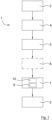
- FIG. 1 disclosing a schematic illustration of a generic production line/apparatus for dry manufacturing rigid cellulose products, generally designated 1.
- the production line 1 is configured for manufacturing rigid cellulose products, generally designated 2, having essentially non-flat general shape from separated cellulose fibres.
- Such a production line 1 may be arranged and set-up according to different well-known ways.
- Cellulose raw material 3 is provided to the production line, and is fed to a separating/disintegrating unit 4 in order to obtain individualized/separated cellulose fibres.
- the separated cellulose fibres are thereafter transported by an air stream/flow to a dispenser of a cellulose blank/sheet forming unit 5.
- the cellulose fibres are laid by the dispenser on a moving or stationary perforated surface of the cellulose blank forming unit 5.
- the cellulose fibre carrying air flow may be generated by suitable device located upstream and/or downstream the perforated surface.
- the generated cellulose blank 6 is transported to a product forming unit 7, whereby rigid cellulose products 2 are formed and discharged from the product forming unit 7.
- the rigid cellulose product 2 is in this embodiment made of a heat-pressed sheet of air-laid cellulose fluff comprising cellulose fibers.
- the cellulose blank forming unit 5 may be configured to generate a continuous cellulose blank and/or discontinuous/discrete cellulose blanks. Preferably discontinuous/discrete cellulose blanks 6 are fed into the product forming unit 7.
- the cellulose raw material 3 may be in the form of reeled pulp or paper, bale of cellulose pulp, paper, etc. and/or sheets of paper, cellulose pulp, etc. In case said cellulose raw material 3 is in the form of sheets and/or reeled pulp or paper, it can be fed directly into the separating unit 4. However, in case said cellulose raw material 3 is in the form of a bale or compact stacks of sheets, etc. one or more shredders and/or one or more additional separating/disintegrating units 4 may be necessary to be used for separating and dosing said cellulose raw material 3 from said bale or sheets in smaller quantities. The shredder(s) prepare cellulose raw material 3 to be accepted by said separating unit 4.
- the separating unit 4 disintegrates the cellulose raw material 3 into separated cellulose fibres.
- Said one or plurality of shredder(s) are arranged before said one or a plurality of separating unit(s) 4, so that an output of one of said shredder is connected to an input of one of said separating units 4.
- the shredders may be arranged in parallel to each other or in series with each other, and the disintegrating units 4 may be arranged in parallel to each other or in series with each other.
- the shredders and the disintegrating units 4 together constitute a cellulose fibre separating unit, arranged upstream the cellulose blank forming unit 5.
- Said cellulose raw material 3 may be constituted by virgin cellulose fibres and/or recycled cellulose fibres and may originate from wood pulps such as kraft pulp, sulphite pulp, mechanical pulp, thermomechanical pulp (TMP), chemical treated mechanical pulp, chemi-thermomechanical pulp (CTMP), and/or from non-wood pulps such as bagasse, bamboo, abaca, hemp, flax, cotton.
- wood pulps such as kraft pulp, sulphite pulp, mechanical pulp, thermomechanical pulp (TMP), chemical treated mechanical pulp, chemi-thermomechanical pulp (CTMP), and/or from non-wood pulps such as bagasse, bamboo, abaca, hemp, flax, cotton.
- the separating unit 4 may according to various embodiments be constituted by a hammer mill.
- said separating unit 4 the cellulose raw material is separated into fibres having a normal length in the range of 0,5-70 mm.
- the length of said fibres may be customized by adjusting the internal properties of the separating unit 4 and/or by choosing a different separating unit 4 and/or choosing different cellulose raw material.
- the fibre length for wood pulp is according to various embodiments in the range 0,5-4 mm, preferably in the range 1,7-3,6 mm.
- the fibre length for non-wood pulp is in the range 0,5-70 mm.
- the production line 1 may comprise a pre-compression and/or imprinting unit 8, located downstream the cellulose blank forming unit 5 and upstream the product forming unit 7.
- a pre-compression and/or imprinting unit 8 located downstream the cellulose blank forming unit 5 and upstream the product forming unit 7.
- an air-laid fluffy cellulose blank having a first thickness may be compressed into a cellulose blank having a second thickness, wherein said second thickness is thinner than said first thickness, and/or may be provided with an imprinted pattern.
- the cellulose blank is made more coherent and easier to handle, since the pre-compression/imprinting generates internal bindings between individual cellulose fibres preventing mutual separation of the cellulose fibres.
- the product forming unit 7 comprises a press unit 9, and may optionally comprise a pre-heating unit 10 arranged upstream the press unit 9.
- said cellulose blank 6 may be heated to an elevated temperature before being fed into the press unit 9 of the product forming unit 7.
- said press unit 9 may or may not comprise heating.
- said press unit 9 may be a heated press unit 9 for heating said cellulose blank 6 during pressing.
- preheating of said cellulose blank using a pre-heating unit 10 is optional.
- preheating of the cellulose blank in said pre-heating unit 10 may be combined with a heated press unit 9.
- the rigid cellulose product 2 is made of a heat-pressed sheet of air-laid cellulose fluff comprising cellulose fibers.
- the press unit 9 comprises a moulding tool having a first mould part 11 and a second mould part 12, wherein at least one of the first mould part 11 and the second mould part 12 is/are displaceable back and forth in relation to each other, in order to exert pressure to the cellulose blank 6 loaded therebetween.
- the mutual displacement is disclosed as being vertical, however the mutual displacement may be horizontal or any other suitable angle.
- the cellulose blank 6 loaded into the moulding tool is constituted by an air-laid cellulose blank 6.
- the air-laid cellulose blank 6 may be generated upstream the product forming unit 7 in the same production line and provided to the product forming unit 7, or may be generated at a separate location and provided to the product forming unit 7 via intermediate handling and storage.
- the first mould part 11 of the moulding tool is a female mould part, i.e. having a main recess for receiving the cellulose blank 6, and the second mould part 12 of the moulding tool is a male mould part, i.e. having a main protrusion for cooperation with said recess of the first/female mould part, such that the cellulose blank 6 is pressed into a final rigid non-flat shape.
- a predetermined pressure P1 is applied by the moulding tool between the recess and the protrusion.
- the rigid cellulose product 2 obtains its final rigid non-flat shape, which may have any conceivable non-flat design/shape.
- the edges of the rigid cellulose product 2 are trimmed concurrently with the pressing/forming of the rigid cellulose product 2.
- the predetermined pressure P1 is in the range 40-10000N/cm 2 , preferably in the range 100-4000N/cm 2 . According to various embodiments said predetermined pressures are above 400 N/ cm 2 , and according to various embodiments said predetermined pressures are below 2000 N/ cm 2 . According to various embodiments the cellulose blank 6 loaded into the press unit 9 is constituted by a paperboard/cardboard cellulose blank, instead of the air-laid cellulose blank described above.
- the rigid cellulose product is hereinbelow constituted by an inventive lid 2 made of cellulose fibers.
- the above disclosure concerning a rigid cellulose product is fully applicable to the lid 2.
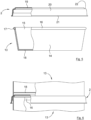
- figure 5 disclosing a set constituted by a container 13 and a lid 2, wherein the lid is shaped according to a first embodiment
- figure 6 disclosing a stack of two containers 13 wherein the lower container 13 is closed by a lid 2 and the upper container 13 is placed on top of the lid 2 of the lower container 13.
- the container 13 comprises a container wall 14 and an opening 15 defined by a circumferential rim/brim 16 of the container wall 14, wherein said rim 16 has a circular outer rim surface 17.
- the outer rim surface 17 of the rim is the circumferential radially most outer surface of the rim 16.
- the rim 16 has an essentially round cross-sectional area wherein the circular outer rim surface 17 is more or less constituted by a circumferential line.
- the rim 16 has an essentially square shaped cross-sectional area.
- the container wall 14 is cylindrical and has a circular cross section in the radial plane, like a tin can or a tube for crisps.
- the cylinder wall 14 may have truncated cone shape, narrowing in the direction away from the opening 15, in accordance with figure 5 embodiment, or may have complete cone shape. Thereby the containers 13 are stackable one inside the other when they are empty, like mugs/cups/trays.
- the cross section of the container wall 14 in the radial plane may have any suitable shape and may differ in shape and/or dimension along the axial extension of the container 13, as long as the outer rim surface 17 of the rim 16 is circular.
- the cylinder 13 may comprise a fixed bottom 18, or may be open in both axial ends, i.e. having two opposite openings 15, like a tube for posters.
- the bottom 18 may be located at the very lower end of the container wall 14, according to figure 5 embodiment, or be located at a distance from the lower end of the container wall 14, according to figure 6 embodiment, or a combination thereof.
- the circular outer rim surface 17 of the rim 16 of the container 13 is located radially outside the envelope surface of the container wall 14.
- the circular outer rim surface 17 of the rim 16 is in flush with the envelope surface of the container wall 14.
- the container 13 may be made of any suitable and rigid material or combination of materials, such as cellulose, paperboard, metal, glass, plastic, etc.
- the lid 2 is a rigid cellulose product thermoformed from an air-laid cellulose blank or from a paperboard cellulose blank, i.e. is made of cellulose fibers.
- the lid 2 comprises a cover plate 19 configured to cover the opening 15 of the container 13, and a skirt 20 connected to the cover plate 19 and configured to engage the circular outer rim surface 17 of the rim 16 of the container 13.
- the lid 2 comprises a radially extending flange 21 at the lower end of the skirt 20, in order to simplify closing and opening of the container 13.
- Said flange 21 is optional. It shall also be pointed out that the flange 21 may be replaced by or supplemented by radially extending lugs (not disclosed) to further simplify closing and opening of the container 13.
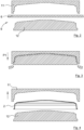
- Figures 5 and 6 disclose a lid 2 according to a first embodiment, wherein the cover plate 19 has a circumferential step 22 at the periphery of the cover plate 19.
- the cover plate 19 is provided a convex general shape, and one purpose is to align and support the upper container 13 in a stack/pile of containers 13 having cylindrical container wall 14 and the bottom 18 offset upwards as disclosed in figure 6 .
- the step 22 also provides stability to the lid 2.
- the cover plate 19 may in the central part thereof comprise further projections and/or recesses.
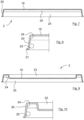
- Figures 7, 8 and 11 disclose a lid 2 according to a second embodiment, wherein the cover plate 19 is flat. It is advantageous to have as few sharp corners/edges as possible since such areas are crack-prone areas during the forming/moulding step.
- the cover plate 19 may comprise projections and/or recesses.
- Figures 9 and 10 disclose a lid 2 according to a third embodiment, wherein the cover plate 19 has a central recess 23.
- the cover plate 19 is provided a concave general shape, and one purpose is to align and support the upper container 13 in a stack/pile of containers 13 having truncated cone shaped container wall 14 as disclosed in figure 5 .
- the recess 23 also provides stability to the lid 2.
- the cover plate 19 may in the central recess 23 thereof comprise further projections and/or recesses.
- step 22 according to the first embodiment of the lid 2 may be combined with the recess 23 according to the third embodiment of the lid 2, in order to obtain a more versatile and multi-application lid 2.
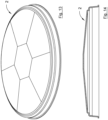
- Figures 13 and 14 disclose a lid 2 according to a fourth embodiment, wherein the cover plate 19 has a circumferential step 22 at the periphery of the cover plate 19 and thereto a dome-shaped centre part of the cover plate 19, i.e. the cover plate 19 has convex general shape.
- the step 22 is optional in this embodiment.
- One purpose of the dome-shaped centre part of the cover plate 19 is to provide stability to the lid 2, another purpose is to enlarge the closed cavity/volume of the container 13 and lid 2.
- the dome-shaped centre part of the cover plate 19 also entails that by being deformed when applying the lid 2 to the container 13, the skirt 20 may be distorted in the radial direction without damaging the cover plate 19 and/or the skirt 20 and at the same time provides a biasing force in the radial direction to the skirt 20.
- the dome-shaped centre part of the cover plate 19 may be semispherical and/or may be composed by several generally flat tiles as disclosed in figures 13 and 14 .
- a first circumferential segment 24 of an inner surface of the skirt 20 has cylindrical shape, i.e. an axially/vertically extending surface segment.
- the first circumferential segment 24 of the inner surface of the skirt 20 is located intermediate a second circumferential segment 25 of the inner surface of the skirt 20 and the cover plate 19.
- the second circumferential segment 25 is adjacent the radial flange 21 of the skirt 20.
- the first circumferential segment 24 is adjacent the cover plate 19.
- the skirt 20 comprises a third circumferential segment of the inner surface of the skirt 20 located intermediate the first circumferential segment 24 and the cover plate 19.
- the cylinder-shaped first circumferential segment 24 of the inner surface of the skirt 20 is configured to engage the circular outer rim surface 17 of the rim 16 of the container 13.
- the cylinder-shaped first circumferential segment 24 of the skirt 20 of the lid 2 has non-circular shape, to engage the circular-shaped outer rim surface 17 of the rim 16 of the container 13.
- the difference in shape and dimensions in the radial plane secures the engagement between the lid 2 and the container 13.
- the inner circumference of the first circumferential segment 24 of the inner surface of the skirt 20 is equal to or less than 102% of the circumference of the circular outer rim surface 17 of the container 13, and is equal to or more than 98% of the circumference of the circular outer rim surface 17 of the container 13.
- the inner circumference of the non-circular first circumferential segment 24 is more or less the same as the circumference of the circular outer rim surface 17, whereby there is low internal tensions in the bindings between individual cellulose fibres at the skirt 20 of the lid 2.
- the inner circumference of the non-circular first circumferential segment 24 is equal to or less than 101% of the circumference of the circular outer rim surface 17, and most preferably equal to or less than the circumference of the circular outer rim surface 17.
- the axial height of the first circumferential segment 24 of the inner surface of the skirt 20 is equal to or more than 1 mm and equal to or less than 5 mm, preferably equal to or more than 1,5 mm and equal to or less than 3 mm.
- the axial height of the first circumferential segment 24 has to be large enough to be able to engage the outer rim surface 17 of the container 13.
- the skirt 20 of the lid 2 has an outer surface 26 located opposite the cylindrical first circumferential segment 24 of the inner surface of the skirt 20, wherein said outer surface 26 has truncated cone shape.
- the thickness of the skirt 20 between the conical outer surface 26 and the cylindrical first circumferential segment 24 of the inner surface will vary from large, adjacent the second circumferential segment 25 of the inner surface of the skirt 20, to small, at the cover plate 19.
- the difference in thickness entails that the density and rigidity of the skirt 20 will vary accordingly.
- the rim 16 of the container 13 may slightly penetrate into the slightly softer surface of the first circumferential segment 24, and thereby the lid 2 is kept harder/firmer to the rim 16 of the container 13.
- the second circumferential segment 25 of the inner surface of the skirt 20 has truncated cone shape, in order to facilitate closing of the lid 2.
- the rim 16 of the container 13 is easily guided by the truncated cone-shaped second circumferential segment 25 towards the first circumferential segment 24. Thereafter the lid 2 is forced downwards at the same time as the first circumferential segment 24 engage the outer rim surface 17.
- the entire outer surface of the skirt 20, except the radial flange 21, is in the shape of a truncated cone, in order to obtain correct pressing/forming of the skirt 20 of the lid 2 during one directional pressing in the mould.
- the second circumferential segment 25 of the inner surface of the skirt 20, as well as the outer surface of the skirt 20, has circular shape.
- the lid 2 is and behaves as a circular lid 2 and may be stacked without having to consider rotational position/orientation of the individual lids 2, since the outer surface of the skirt 20 only engage the second circumferential segment 25 of the inner surface.
- the first circumferential segment 24 of the lid 2 has to have non-circular shape.
- the second circumferential segment 25 of the inner surface of the skirt 20, and/or the outer surface of the skirt 20, may have non-circular shape in accordance with the first circumferential segment 24.
- the first circumferential segment 24 comprises four equidistantly distributed radii 27a-27d, wherein at least one radius 27a of said four radii is the shortest radius of the first circumferential segment 24, and is less than the radius of the circular outer rim surface 17 of the container 13, and is equal to or more than 98% of the radius of the circular outer rim surface 17.
- said at least one radius 27a of said four radii that is the shortest is equal to or more than 99% of the radius of the circular outer rim surface 17.
- the radius 27c that is located opposite the at least one radius 27a of said four radii that is the shortest radius has the same length as said at least one radius 27a.
- At least one other radius 27b of the four radii is the longest radius of the first circumferential segment 24 and is more than the radius of the circular outer rim surface 17 of the container 13 and is equal to or less than 102% of the radius of the circular outer rim surface 17.
- said at least one other radius 27b of the four radii that is the longest is equal to or less than 101% of the radius of the circular outer rim surface 17.
- the radius 27d that is located opposite the at least one other radius 27b of said four radii that is the largest radius has the same length as said at least one other radius 27b.
- the non-circular first circumferential segment 24 has oval shape, having one large diameter (radii 27b and 27d) and one small diameter (radii 27a and 27c) perpendicular to the large diameter.
- two mutually adjacent radii (27a and 27d) have the same length, and the other two mutually adjacent radii (27b and 27c) have the same length.
- three radii 27b-27d has the same length and the fourth radius 27a is shorter (or longer).
- the radius of the cylinder-shaped first circumferential segment 24 of the inner surface of the skirt 20 varies uniformly between two adjacent radii of the four equidistantly distributed radii 27a-27d.
- the smallest inner circumference of the second circumferential segment 25 of the inner surface of the skirt 20 is greater than the greatest of: the circumference of the circular outer rim surface 17 of the container 13, and the inner circumference of the first circumferential segment 24 of the inner surface of the skirt 20.
- the method comprises the steps of forming the cover plate 19 and forming the skirt 20 connected to the cover plate 19, wherein the first circumferential segment 24 of the inner surface of the skirt 20 is given cylindrical shape and is located intermediate the second circumferential segment 25 and the cover plate 19.
- the method also comprises the step of forming the cylinder-shaped first circumferential segment 24 of the skirt 20 into non-circular shape, wherein the inner circumference of the first circumferential segment 24 is made equal to or less than 102% of the circumference of the circular outer rim surface 17 and is made equal to or more than 98% of the circumference of the circular outer rim surface 17.
- the final rigid cellulose product may be constituted by three or more segments, wherein each pair of neighbouring segments are joined/connected to each other according to the present invention.
Landscapes
- Engineering & Computer Science (AREA)
- Mechanical Engineering (AREA)
- Closures For Containers (AREA)
Priority Applications (4)
| Application Number | Priority Date | Filing Date | Title |
|---|---|---|---|
| EP23174541.5A EP4467480A1 (de) | 2023-05-22 | 2023-05-22 | Deckel zur verwendung zusammen mit einem behälter sowie satz aus behälter und deckel und verfahren zur herstellung solch eines deckels |
| PCT/EP2024/063899 WO2024240736A1 (en) | 2023-05-22 | 2024-05-21 | Lid to be used together with a container as well as set of container and lid and a method for manufacturing such a lid |
| CN202480034088.0A CN121175249A (zh) | 2023-05-22 | 2024-05-21 | 与容器一起使用的盖、容器和盖的套件以及用于制造这种盖的方法 |
| AU2024276808A AU2024276808A1 (en) | 2023-05-22 | 2024-05-21 | Lid to be used together with a container as well as set of container and lid and a method for manufacturing such a lid |
Applications Claiming Priority (1)
| Application Number | Priority Date | Filing Date | Title |
|---|---|---|---|
| EP23174541.5A EP4467480A1 (de) | 2023-05-22 | 2023-05-22 | Deckel zur verwendung zusammen mit einem behälter sowie satz aus behälter und deckel und verfahren zur herstellung solch eines deckels |
Publications (1)
| Publication Number | Publication Date |
|---|---|
| EP4467480A1 true EP4467480A1 (de) | 2024-11-27 |
Family
ID=86497699
Family Applications (1)
| Application Number | Title | Priority Date | Filing Date |
|---|---|---|---|
| EP23174541.5A Pending EP4467480A1 (de) | 2023-05-22 | 2023-05-22 | Deckel zur verwendung zusammen mit einem behälter sowie satz aus behälter und deckel und verfahren zur herstellung solch eines deckels |
Country Status (4)
| Country | Link |
|---|---|
| EP (1) | EP4467480A1 (de) |
| CN (1) | CN121175249A (de) |
| AU (1) | AU2024276808A1 (de) |
| WO (1) | WO2024240736A1 (de) |
Citations (8)
| Publication number | Priority date | Publication date | Assignee | Title |
|---|---|---|---|---|
| US2350950A (en) * | 1943-05-21 | 1944-06-06 | Lee M Wiley | Fibrous, covered container |
| FR967699A (fr) * | 1948-06-08 | 1950-11-09 | Dispositif de fermeture énergique et étanche de récipients en matière plastique | |
| US3104045A (en) * | 1960-08-12 | 1963-09-17 | American Can Co | Container and closure therefor |
| US20130334228A1 (en) | 2012-06-13 | 2013-12-19 | Alois SCHMIDTNER | Multipart cover made of paper material and method for producing a multipart cover |
| DE102014219272A1 (de) * | 2014-09-24 | 2016-03-24 | Ptm Packaging Tools Machinery Pte. Ltd. | Deckel für einen Getränkebecher, Becheranordnung und Verfahren zur Herstellung eines Deckels |
| EP3736099A1 (de) | 2016-03-18 | 2020-11-11 | PulPac AB | Verfahren zur herstellung eines celluloseprodukts mit einer pressformvorrichtung, pressformvorrichtung und celluloseprodukt |
| WO2021140104A1 (en) * | 2020-01-06 | 2021-07-15 | Hanpak Limited | A lid |
| CA3037920C (en) * | 2018-04-05 | 2022-11-29 | Joel S. Harris | Multi-function container lid |
-
2023
- 2023-05-22 EP EP23174541.5A patent/EP4467480A1/de active Pending
-
2024
- 2024-05-21 WO PCT/EP2024/063899 patent/WO2024240736A1/en not_active Ceased
- 2024-05-21 AU AU2024276808A patent/AU2024276808A1/en active Pending
- 2024-05-21 CN CN202480034088.0A patent/CN121175249A/zh active Pending
Patent Citations (9)
| Publication number | Priority date | Publication date | Assignee | Title |
|---|---|---|---|---|
| US2350950A (en) * | 1943-05-21 | 1944-06-06 | Lee M Wiley | Fibrous, covered container |
| FR967699A (fr) * | 1948-06-08 | 1950-11-09 | Dispositif de fermeture énergique et étanche de récipients en matière plastique | |
| US3104045A (en) * | 1960-08-12 | 1963-09-17 | American Can Co | Container and closure therefor |
| US20130334228A1 (en) | 2012-06-13 | 2013-12-19 | Alois SCHMIDTNER | Multipart cover made of paper material and method for producing a multipart cover |
| DE102012216631A1 (de) * | 2012-06-13 | 2013-12-19 | Michael Hörauf Maschinenfabrik GmbH & Co. KG | Mehrteiliger Deckel aus einem Papiermaterial und Verfahren zum Herstellen eines mehrteiligen Deckels |
| DE102014219272A1 (de) * | 2014-09-24 | 2016-03-24 | Ptm Packaging Tools Machinery Pte. Ltd. | Deckel für einen Getränkebecher, Becheranordnung und Verfahren zur Herstellung eines Deckels |
| EP3736099A1 (de) | 2016-03-18 | 2020-11-11 | PulPac AB | Verfahren zur herstellung eines celluloseprodukts mit einer pressformvorrichtung, pressformvorrichtung und celluloseprodukt |
| CA3037920C (en) * | 2018-04-05 | 2022-11-29 | Joel S. Harris | Multi-function container lid |
| WO2021140104A1 (en) * | 2020-01-06 | 2021-07-15 | Hanpak Limited | A lid |
Also Published As
| Publication number | Publication date |
|---|---|
| AU2024276808A1 (en) | 2025-10-30 |
| WO2024240736A1 (en) | 2024-11-28 |
| CN121175249A (zh) | 2025-12-19 |
Similar Documents
| Publication | Publication Date | Title |
|---|---|---|
| CN101229855B (zh) | 一次性带槽纹的纸板盘及其制造方法 | |
| US4609140A (en) | Rigid paperboard container and method and apparatus for producing same | |
| US20240408789A1 (en) | Press molding method of a cup shaped fiber product, a fiber press mold and a cup shaped fiber product | |
| JP7331451B2 (ja) | カバー材、および、その製造方法と二次加工用型 | |
| EP4467480A1 (de) | Deckel zur verwendung zusammen mit einem behälter sowie satz aus behälter und deckel und verfahren zur herstellung solch eines deckels | |
| AU561748B2 (en) | Rigid paperboard container and method and apparatus for producing the same | |
| EP4527608A1 (de) | Vorrichtung und verfahren zur trockenherstellung von steifen zelluloseprodukten | |
| EP4650161A1 (de) | Verfahren und produktformungseinheit zur trockenherstellung von steifen celluloseprodukten | |
| EP4520496A1 (de) | Vorrichtung zur trockenherstellung von steifen zelluloseprodukten | |
| EP4527610A1 (de) | Vorrichtung und verfahren zur trockenherstellung von steifen zelluloseprodukten | |
| EP4656369A1 (de) | Produktformungseinheit und verfahren zur trockenherstellung von starren celluloseprodukten | |
| EP4613472A1 (de) | Produktformungseinheit zur trockenherstellung von starren celluloseprodukten und verfahren zur steuerung solch einer produktformungseinheit | |
| EP4678363A1 (de) | Verfahren und vorrichtung zur trockenherstellung von steifen zelluloseprodukten | |
| EP4570488A1 (de) | Verfahren und vorrichtung zur trockenherstellung einer steifen zelluloseschale und steife zelluloseschale | |
| EP4640392A1 (de) | Produktformungseinheit zur trockenherstellung von starren celluloseprodukten | |
| EP4590475A1 (de) | Pressformverfahren für ein faserprodukt, faserpressform und faserprodukt | |
| EP4653184A1 (de) | Vorrichtung und verfahren zur trockenherstellung von steifen zelluloseprodukten | |
| EP4699767A1 (de) | Produktformungseinheit und verfahren zur trockenherstellung von starren celluloseprodukten | |
| EP4477373A1 (de) | Verfahren und vorrichtung zur trockenherstellung von steifen zelluloseprodukten | |
| EP4656368A1 (de) | Produktformungseinheit und verfahren zur trockenherstellung von starren celluloseprodukten | |
| TW202448373A (zh) | 具有提供增加的剛度的側壁特徵的紙板容器及其製造方法 | |
| WO2025132692A1 (en) | Multi-cavity forming mould system and method for dry-forming cellulose products in a multi-cavity forming mould system | |
| CN119968254A (zh) | 纤维制品的压制成型方法、纤维压制模具和纤维制品 |
Legal Events
| Date | Code | Title | Description |
|---|---|---|---|
| PUAI | Public reference made under article 153(3) epc to a published international application that has entered the european phase |
Free format text: ORIGINAL CODE: 0009012 |
|
| STAA | Information on the status of an ep patent application or granted ep patent |
Free format text: STATUS: THE APPLICATION HAS BEEN PUBLISHED |
|
| AK | Designated contracting states |
Kind code of ref document: A1 Designated state(s): AL AT BE BG CH CY CZ DE DK EE ES FI FR GB GR HR HU IE IS IT LI LT LU LV MC ME MK MT NL NO PL PT RO RS SE SI SK SM TR |
|
| STAA | Information on the status of an ep patent application or granted ep patent |
Free format text: STATUS: REQUEST FOR EXAMINATION WAS MADE |
|
| 17P | Request for examination filed |
Effective date: 20250520 |
|
| STAA | Information on the status of an ep patent application or granted ep patent |
Free format text: STATUS: EXAMINATION IS IN PROGRESS |
|
| 17Q | First examination report despatched |
Effective date: 20251006 |
|
| RIN1 | Information on inventor provided before grant (corrected) |
Inventor name: JOHANSSON, ADAM |