EP4467443A2 - Liquefied gas storage tank and ship comprising same - Google Patents
Liquefied gas storage tank and ship comprising same Download PDFInfo
- Publication number
- EP4467443A2 EP4467443A2 EP24197640.6A EP24197640A EP4467443A2 EP 4467443 A2 EP4467443 A2 EP 4467443A2 EP 24197640 A EP24197640 A EP 24197640A EP 4467443 A2 EP4467443 A2 EP 4467443A2
- Authority
- EP
- European Patent Office
- Prior art keywords
- corner
- primary
- barrier
- flat
- block
- Prior art date
- Legal status (The legal status is an assumption and is not a legal conclusion. Google has not performed a legal analysis and makes no representation as to the accuracy of the status listed.)
- Pending
Links
Images













Classifications
-
- F—MECHANICAL ENGINEERING; LIGHTING; HEATING; WEAPONS; BLASTING
- F17—STORING OR DISTRIBUTING GASES OR LIQUIDS
- F17C—VESSELS FOR CONTAINING OR STORING COMPRESSED, LIQUEFIED OR SOLIDIFIED GASES; FIXED-CAPACITY GAS-HOLDERS; FILLING VESSELS WITH, OR DISCHARGING FROM VESSELS, COMPRESSED, LIQUEFIED, OR SOLIDIFIED GASES
- F17C3/00—Vessels not under pressure
- F17C3/02—Vessels not under pressure with provision for thermal insulation
- F17C3/025—Bulk storage in barges or on ships
-
- B—PERFORMING OPERATIONS; TRANSPORTING
- B63—SHIPS OR OTHER WATERBORNE VESSELS; RELATED EQUIPMENT
- B63B—SHIPS OR OTHER WATERBORNE VESSELS; EQUIPMENT FOR SHIPPING
- B63B25/00—Load-accommodating arrangements, e.g. stowing, trimming; Vessels characterised thereby
- B63B25/02—Load-accommodating arrangements, e.g. stowing, trimming; Vessels characterised thereby for bulk goods
- B63B25/08—Load-accommodating arrangements, e.g. stowing, trimming; Vessels characterised thereby for bulk goods fluid
- B63B25/12—Load-accommodating arrangements, e.g. stowing, trimming; Vessels characterised thereby for bulk goods fluid closed
- B63B25/16—Load-accommodating arrangements, e.g. stowing, trimming; Vessels characterised thereby for bulk goods fluid closed heat-insulated
-
- F—MECHANICAL ENGINEERING; LIGHTING; HEATING; WEAPONS; BLASTING
- F17—STORING OR DISTRIBUTING GASES OR LIQUIDS
- F17C—VESSELS FOR CONTAINING OR STORING COMPRESSED, LIQUEFIED OR SOLIDIFIED GASES; FIXED-CAPACITY GAS-HOLDERS; FILLING VESSELS WITH, OR DISCHARGING FROM VESSELS, COMPRESSED, LIQUEFIED, OR SOLIDIFIED GASES
- F17C3/00—Vessels not under pressure
- F17C3/02—Vessels not under pressure with provision for thermal insulation
- F17C3/025—Bulk storage in barges or on ships
- F17C3/027—Wallpanels for so-called membrane tanks
-
- F—MECHANICAL ENGINEERING; LIGHTING; HEATING; WEAPONS; BLASTING
- F17—STORING OR DISTRIBUTING GASES OR LIQUIDS
- F17C—VESSELS FOR CONTAINING OR STORING COMPRESSED, LIQUEFIED OR SOLIDIFIED GASES; FIXED-CAPACITY GAS-HOLDERS; FILLING VESSELS WITH, OR DISCHARGING FROM VESSELS, COMPRESSED, LIQUEFIED, OR SOLIDIFIED GASES
- F17C3/00—Vessels not under pressure
- F17C3/02—Vessels not under pressure with provision for thermal insulation
- F17C3/04—Vessels not under pressure with provision for thermal insulation by insulating layers
-
- F—MECHANICAL ENGINEERING; LIGHTING; HEATING; WEAPONS; BLASTING
- F17—STORING OR DISTRIBUTING GASES OR LIQUIDS
- F17C—VESSELS FOR CONTAINING OR STORING COMPRESSED, LIQUEFIED OR SOLIDIFIED GASES; FIXED-CAPACITY GAS-HOLDERS; FILLING VESSELS WITH, OR DISCHARGING FROM VESSELS, COMPRESSED, LIQUEFIED, OR SOLIDIFIED GASES
- F17C2201/00—Vessel construction, in particular geometry, arrangement or size
- F17C2201/01—Shape
- F17C2201/0147—Shape complex
- F17C2201/0157—Polygonal
-
- F—MECHANICAL ENGINEERING; LIGHTING; HEATING; WEAPONS; BLASTING
- F17—STORING OR DISTRIBUTING GASES OR LIQUIDS
- F17C—VESSELS FOR CONTAINING OR STORING COMPRESSED, LIQUEFIED OR SOLIDIFIED GASES; FIXED-CAPACITY GAS-HOLDERS; FILLING VESSELS WITH, OR DISCHARGING FROM VESSELS, COMPRESSED, LIQUEFIED, OR SOLIDIFIED GASES
- F17C2201/00—Vessel construction, in particular geometry, arrangement or size
- F17C2201/05—Size
- F17C2201/052—Size large (>1000 m3)
-
- F—MECHANICAL ENGINEERING; LIGHTING; HEATING; WEAPONS; BLASTING
- F17—STORING OR DISTRIBUTING GASES OR LIQUIDS
- F17C—VESSELS FOR CONTAINING OR STORING COMPRESSED, LIQUEFIED OR SOLIDIFIED GASES; FIXED-CAPACITY GAS-HOLDERS; FILLING VESSELS WITH, OR DISCHARGING FROM VESSELS, COMPRESSED, LIQUEFIED, OR SOLIDIFIED GASES
- F17C2203/00—Vessel construction, in particular walls or details thereof
- F17C2203/01—Reinforcing or suspension means
- F17C2203/011—Reinforcing means
-
- F—MECHANICAL ENGINEERING; LIGHTING; HEATING; WEAPONS; BLASTING
- F17—STORING OR DISTRIBUTING GASES OR LIQUIDS
- F17C—VESSELS FOR CONTAINING OR STORING COMPRESSED, LIQUEFIED OR SOLIDIFIED GASES; FIXED-CAPACITY GAS-HOLDERS; FILLING VESSELS WITH, OR DISCHARGING FROM VESSELS, COMPRESSED, LIQUEFIED, OR SOLIDIFIED GASES
- F17C2203/00—Vessel construction, in particular walls or details thereof
- F17C2203/03—Thermal insulations
- F17C2203/0304—Thermal insulations by solid means
- F17C2203/0329—Foam
- F17C2203/0333—Polyurethane
-
- F—MECHANICAL ENGINEERING; LIGHTING; HEATING; WEAPONS; BLASTING
- F17—STORING OR DISTRIBUTING GASES OR LIQUIDS
- F17C—VESSELS FOR CONTAINING OR STORING COMPRESSED, LIQUEFIED OR SOLIDIFIED GASES; FIXED-CAPACITY GAS-HOLDERS; FILLING VESSELS WITH, OR DISCHARGING FROM VESSELS, COMPRESSED, LIQUEFIED, OR SOLIDIFIED GASES
- F17C2203/00—Vessel construction, in particular walls or details thereof
- F17C2203/03—Thermal insulations
- F17C2203/0304—Thermal insulations by solid means
- F17C2203/0358—Thermal insulations by solid means in form of panels
-
- F—MECHANICAL ENGINEERING; LIGHTING; HEATING; WEAPONS; BLASTING
- F17—STORING OR DISTRIBUTING GASES OR LIQUIDS
- F17C—VESSELS FOR CONTAINING OR STORING COMPRESSED, LIQUEFIED OR SOLIDIFIED GASES; FIXED-CAPACITY GAS-HOLDERS; FILLING VESSELS WITH, OR DISCHARGING FROM VESSELS, COMPRESSED, LIQUEFIED, OR SOLIDIFIED GASES
- F17C2203/00—Vessel construction, in particular walls or details thereof
- F17C2203/06—Materials for walls or layers thereof; Properties or structures of walls or their materials
- F17C2203/0602—Wall structures; Special features thereof
- F17C2203/0612—Wall structures
- F17C2203/0626—Multiple walls
-
- F—MECHANICAL ENGINEERING; LIGHTING; HEATING; WEAPONS; BLASTING
- F17—STORING OR DISTRIBUTING GASES OR LIQUIDS
- F17C—VESSELS FOR CONTAINING OR STORING COMPRESSED, LIQUEFIED OR SOLIDIFIED GASES; FIXED-CAPACITY GAS-HOLDERS; FILLING VESSELS WITH, OR DISCHARGING FROM VESSELS, COMPRESSED, LIQUEFIED, OR SOLIDIFIED GASES
- F17C2221/00—Handled fluid, in particular type of fluid
- F17C2221/03—Mixtures
- F17C2221/032—Hydrocarbons
-
- F—MECHANICAL ENGINEERING; LIGHTING; HEATING; WEAPONS; BLASTING
- F17—STORING OR DISTRIBUTING GASES OR LIQUIDS
- F17C—VESSELS FOR CONTAINING OR STORING COMPRESSED, LIQUEFIED OR SOLIDIFIED GASES; FIXED-CAPACITY GAS-HOLDERS; FILLING VESSELS WITH, OR DISCHARGING FROM VESSELS, COMPRESSED, LIQUEFIED, OR SOLIDIFIED GASES
- F17C2221/00—Handled fluid, in particular type of fluid
- F17C2221/03—Mixtures
- F17C2221/032—Hydrocarbons
- F17C2221/033—Methane, e.g. natural gas, CNG, LNG, GNL, GNC, PLNG
-
- F—MECHANICAL ENGINEERING; LIGHTING; HEATING; WEAPONS; BLASTING
- F17—STORING OR DISTRIBUTING GASES OR LIQUIDS
- F17C—VESSELS FOR CONTAINING OR STORING COMPRESSED, LIQUEFIED OR SOLIDIFIED GASES; FIXED-CAPACITY GAS-HOLDERS; FILLING VESSELS WITH, OR DISCHARGING FROM VESSELS, COMPRESSED, LIQUEFIED, OR SOLIDIFIED GASES
- F17C2221/00—Handled fluid, in particular type of fluid
- F17C2221/03—Mixtures
- F17C2221/032—Hydrocarbons
- F17C2221/035—Propane butane, e.g. LPG, GPL
-
- F—MECHANICAL ENGINEERING; LIGHTING; HEATING; WEAPONS; BLASTING
- F17—STORING OR DISTRIBUTING GASES OR LIQUIDS
- F17C—VESSELS FOR CONTAINING OR STORING COMPRESSED, LIQUEFIED OR SOLIDIFIED GASES; FIXED-CAPACITY GAS-HOLDERS; FILLING VESSELS WITH, OR DISCHARGING FROM VESSELS, COMPRESSED, LIQUEFIED, OR SOLIDIFIED GASES
- F17C2223/00—Handled fluid before transfer, i.e. state of fluid when stored in the vessel or before transfer from the vessel
- F17C2223/01—Handled fluid before transfer, i.e. state of fluid when stored in the vessel or before transfer from the vessel characterised by the phase
- F17C2223/0146—Two-phase
- F17C2223/0153—Liquefied gas, e.g. LPG, GPL
-
- F—MECHANICAL ENGINEERING; LIGHTING; HEATING; WEAPONS; BLASTING
- F17—STORING OR DISTRIBUTING GASES OR LIQUIDS
- F17C—VESSELS FOR CONTAINING OR STORING COMPRESSED, LIQUEFIED OR SOLIDIFIED GASES; FIXED-CAPACITY GAS-HOLDERS; FILLING VESSELS WITH, OR DISCHARGING FROM VESSELS, COMPRESSED, LIQUEFIED, OR SOLIDIFIED GASES
- F17C2223/00—Handled fluid before transfer, i.e. state of fluid when stored in the vessel or before transfer from the vessel
- F17C2223/01—Handled fluid before transfer, i.e. state of fluid when stored in the vessel or before transfer from the vessel characterised by the phase
- F17C2223/0146—Two-phase
- F17C2223/0153—Liquefied gas, e.g. LPG, GPL
- F17C2223/0161—Liquefied gas, e.g. LPG, GPL cryogenic, e.g. LNG, GNL, PLNG
-
- F—MECHANICAL ENGINEERING; LIGHTING; HEATING; WEAPONS; BLASTING
- F17—STORING OR DISTRIBUTING GASES OR LIQUIDS
- F17C—VESSELS FOR CONTAINING OR STORING COMPRESSED, LIQUEFIED OR SOLIDIFIED GASES; FIXED-CAPACITY GAS-HOLDERS; FILLING VESSELS WITH, OR DISCHARGING FROM VESSELS, COMPRESSED, LIQUEFIED, OR SOLIDIFIED GASES
- F17C2223/00—Handled fluid before transfer, i.e. state of fluid when stored in the vessel or before transfer from the vessel
- F17C2223/03—Handled fluid before transfer, i.e. state of fluid when stored in the vessel or before transfer from the vessel characterised by the pressure level
- F17C2223/033—Small pressure, e.g. for liquefied gas
-
- F—MECHANICAL ENGINEERING; LIGHTING; HEATING; WEAPONS; BLASTING
- F17—STORING OR DISTRIBUTING GASES OR LIQUIDS
- F17C—VESSELS FOR CONTAINING OR STORING COMPRESSED, LIQUEFIED OR SOLIDIFIED GASES; FIXED-CAPACITY GAS-HOLDERS; FILLING VESSELS WITH, OR DISCHARGING FROM VESSELS, COMPRESSED, LIQUEFIED, OR SOLIDIFIED GASES
- F17C2260/00—Purposes of gas storage and gas handling
- F17C2260/03—Dealing with losses
- F17C2260/031—Dealing with losses due to heat transfer
- F17C2260/033—Dealing with losses due to heat transfer by enhancing insulation
-
- F—MECHANICAL ENGINEERING; LIGHTING; HEATING; WEAPONS; BLASTING
- F17—STORING OR DISTRIBUTING GASES OR LIQUIDS
- F17C—VESSELS FOR CONTAINING OR STORING COMPRESSED, LIQUEFIED OR SOLIDIFIED GASES; FIXED-CAPACITY GAS-HOLDERS; FILLING VESSELS WITH, OR DISCHARGING FROM VESSELS, COMPRESSED, LIQUEFIED, OR SOLIDIFIED GASES
- F17C2270/00—Applications
- F17C2270/01—Applications for fluid transport or storage
- F17C2270/0102—Applications for fluid transport or storage on or in the water
- F17C2270/0105—Ships
- F17C2270/0107—Wall panels
-
- Y—GENERAL TAGGING OF NEW TECHNOLOGICAL DEVELOPMENTS; GENERAL TAGGING OF CROSS-SECTIONAL TECHNOLOGIES SPANNING OVER SEVERAL SECTIONS OF THE IPC; TECHNICAL SUBJECTS COVERED BY FORMER USPC CROSS-REFERENCE ART COLLECTIONS [XRACs] AND DIGESTS
- Y02—TECHNOLOGIES OR APPLICATIONS FOR MITIGATION OR ADAPTATION AGAINST CLIMATE CHANGE
- Y02E—REDUCTION OF GREENHOUSE GAS [GHG] EMISSIONS, RELATED TO ENERGY GENERATION, TRANSMISSION OR DISTRIBUTION
- Y02E60/00—Enabling technologies; Technologies with a potential or indirect contribution to GHG emissions mitigation
- Y02E60/30—Hydrogen technology
- Y02E60/32—Hydrogen storage
Definitions
- the present disclosure relates to a liquefied gas storage tank and a ship including the same.
- liquefied gas such as liquefied natural gas (LNG) and liquefied petroleum gas (LPG) is widely used to replace gasoline or diesel.
- LNG liquefied natural gas
- LPG liquefied petroleum gas
- LNG RV (Regasification Vessel), LNG FPSO (Floating, Production, Storage and Offloading), LNG FSRU (Floating Storage and Regasification Unit), etc.
- storage tanks (so-called “cargo holds") are installed for storing LNG in the cryogenic liquid state, and in accordance with IMO environmental regulations, using LNG fuel tanks in large-scale container ships and various cargo ships is becoming a reality.
- the liquefied gas storage tank may generate boil-off gas (BOG) due to thermal intrusion from the outside, and it is a key technology in the design of a liquefied gas storage tank to lower the boil-off rate (BOR), which is the vaporization rate of the boil-off gas through an insulating design. Additionally, it may be also necessary to secure the mechanical strength of insulating panels as the liquefied gas storage tank is exposed to various loads such as sloshing.
- BOG boil-off gas
- BOR boil-off rate
- the present disclosure has been proposed to solve the problems of the related art as described above, and an object of the present disclosure is to provide a liquefied gas storage tank and a ship including the same that are capable of reducing the burden of low temperature, sloshing, and stress of the corner secondary barrier by improving the structure of the corner block.
- a liquefied gas storage tank includes: a flat block including a flat primary insulating wall disposed on a flat portion on a first surface or a second surface at different angles forming a storage space for accommodating liquefied gas, the flat primary insulating wall securing a flat primary barrier made of metal and being disposed on the outside of the flat primary barrier, a flat secondary barrier disposed on the outside of the flat primary insulating wall, and a flat secondary insulating wall disposed on the outside of the flat secondary barrier; and a corner block including a corner primary insulating wall disposed in a corner portion where the first surface and the second surface meet, the corner primary insulating wall securing a corner primary barrier made of metal and being disposed on the outside of the corner primary barrier, a corner secondary barrier disposed on the outside of the corner primary insulating wall, and a corner secondary insulating wall disposed on the outside of the corner secondary barrier, wherein the corner primary insulating wall includes an outer primary plywood secured to the corner secondary
- the corner primary insulation wall may include: an inner first fixing portion and an inner second fixing portion disposed on the inside of the first and second surfaces, respectively, and including the outer primary plywood, the corner primary insulation material, and the inner primary plywood; and an inner bent portion configured by filling an insulation material between the inner first fixing portion and the inner second fixing portion.
- the corner primary insulation material may be a high-density polyurethane foam
- the insulation material of the inner bent portion may be a low-density polyurethane foam
- the corner primary barrier may secured to the inner primary plywood of the inner first fixing portion and the inner primary plywood of the inner second fixing portion, and provided to be bent on an inner surface of the insulation material of the inner bent portion.
- the corner secondary insulation wall may be secured to the inside of the first and second surfaces, respectively, and may include an outer first fixing portion and an outer second fixing portion including an inner secondary plywood, a corner secondary insulation material, and an outer secondary plywood sequentially arranged to the outside of the corner secondary barrier, and side surfaces of the first outer fixing portion secured to the first surface and the outer second fixing portion secured to the second surface facing each other may be provided to be inclined in a direction dividing the corner portion.
- corner primary insulation wall of the corner block connected to the flat primary insulation wall of the flat block may have the same or similar thickness to that of the corner secondary thermal insulation wall of the corner block connected to the flat secondary thermal insulation wall of the flat block.
- a liquefied gas storage tank includes a corner block disposed at a corner portion where a first surface and a second surface meet at different angles to form a storage space for accommodating liquefied gas
- the corner block includes a lower block provided inside the first and second surfaces and formed of a single board, a plurality of upper blocks disposed adjacently on the lower block and bonded to each other, and an upper connection block that is bonded to upper surfaces of the lower blocks disposed adjacent to each other and connects the lower blocks
- the upper block (or the upper connection block) may include a barrier fixing member provided to be bent at a predetermined angle on the inside of the first and second surfaces, securing a corner primary barrier made of metal, and disposed on the outside of the corner primary barrier, an inner primary plywood (or corner first connecting plywood) disposed on the outside of the barrier fixing member, a corner primary insulation material (or corner connecting insulation material) disposed on the outside of the inner primary plywood (or the corner first connection plywood), and an outer primary plywood (
- the barrier fixing member may be bolted to the inner primary plywood (or the corner first connecting plywood).
- filling of a separate insulation material may be carried out or omitted between the corner primary insulation materials of the upper blocks disposed adjacent to each other.
- filling of a separate insulation material may be carried out or omitted between the corner primary insulation material of the upper block and the corner connecting insulation material of the upper connecting block disposed adjacent to each other.
- a liquefied gas storage tank and a ship including the same of the present disclosure may reduce the burden of low temperature, sloshing, and stress of the corner secondary barrier by improving the structure of the corner block.
- the liquefied gas storage tank and the ship having the same of the present disclosure may form the inner first and second fixing portions for holding the barrier fixing member to which the corner primary barrier is secured in the corner block not only with plywood, but in combination of polyurethane foam insulation, thereby improving insulation compared to the related art including plywood only, and reducing the associated weight and costs.
- the liquefied gas storage tank and the ship having the same of the present disclosure may reduce the burden of the low temperature and sloshing of the corner secondary barrier as the thickness of the corner primary insulating wall becomes relatively thicker (however, the thickness of the corner secondary insulating wall is sufficient to maintain the mechanical strength at a certain level). Furthermore, it is possible to prevent damages to the secondary corner barriers as well as reduce the low temperature load on the corner secondary barriers to prevent any brittle fracture of the hull.
- the liquefied gas storage tank and the ship having the same of the present disclosure may allow the corner secondary barrier to increase a length of the non-adhesive portion to the corner secondary insulating wall, thereby reducing the probability of damages to the corner secondary barrier including the corner connecting barrier due to the increased flexibility of the corner secondary barrier, allowing the corner secondary barrier to easily absorb the hull deformation, and reducing the low temperature stress.
- the liquefied gas storage tank and the ship having the same of the present disclosure may reduce the bending angle of the corner primary barrier by the inner intermediate fixing portion, thereby reducing the burden of sloshing in the corner primary barrier and increasing the mechanical strength of the corner portion.
- the liquefied gas storage tank and the ship having the same of the present disclosure may further increase the thermal insulation performance in the corner portion by the low-density polyurethane foam.
- the liquefied gas storage tank and the ship having the same of the present disclosure may further prevent damages to the corner secondary barrier due to the increased flexibility of the corner secondary barrier including the corner connecting barrier formed on top of the glass wool.
- the liquefied gas storage tank and the ship having the same of the present disclosure may prevent damages to the corner secondary barrier secured to the outer fixing portion as contraction or expansion stress caused by the temperature of the outer fixing portion is alleviated by respective gaps formed between the first outer fixing portion and the outer intermediate fixing portion and between the outer second fixing portion and the outer intermediate fixing portion compared to the conventional one gap configuration.
- the liquefied gas storage tank and the ship having the same of the present disclosure may allow the corner secondary barrier to protrude and bend outward, increasing the length of the non-adhesive portion to the corner secondary insulating wall.
- the corner secondary barrier due to the increased flexibility of the corner secondary barrier, not only the probability of damages to the corner secondary barrier including the corner connecting barrier may be further reduced, but also the corner secondary barrier may easily absorb the hull deformation, and the low temperature stress may be further reduced.
- the liquefied gas storage tank and the ship having the same of the present disclosure may facilitate the installation handling of the barrier fixing member through the stepped portion between the adjacent inner first plywood, and reduce the consumption of the packing material because the packing material only needs to be applied on the stepped portion.
- the liquefied gas storage tank and the ship having the same of the present disclosure by not providing a reinforcing member such as a stiffener on a rear surface of the barrier fixing member, the weight of the barrier fixing member itself may be reduced, and welding for attaching the reinforcing member may be omitted, thereby reducing the welding time and increasing the precision. Also, the liquefied gas storage tank and the ship having the same of the present disclosure may improve the system stability by uniformly distributing stress generated in the portion bent at a right angle or an obtuse angle such that the frequency of damages occurring in the bent portion may be reduced, and repair may be minimized compared to the conventional wall fixing member with a stiffener.
- a reinforcing member such as a stiffener
- the liquefied gas storage tank and the ship having the same of the present disclosure by providing a chamfered or groove shape as a squeeze-out identifier to each of the outer primary plywood and the corner second connecting plywood, which are the lower layers of the upper block and the upper connecting block, respectively, it is possible to reduce the weight of each of the upper block and upper connection block, and to improve the system stability by directly checking the adhesive squeezed out with the naked eye after applying the adhesive on each of the upper block and upper connecting block.
- the liquefied gas storage tank and the ship having the same of the present disclosure by providing a stuffing piece for inserting into a first stepped space formed between the inner primary plywood of the neighboring upper block as well as a second stepped space formed between the inner primary plywood of the upper block and the corner first connecting plywood of the upper connecting block, it is possible to keep constant the gap distance between the neighboring upper blocks and the gap distance between the upper block and the upper connecting block, and to secure the inner bent portion of the upper block and the corner connecting bent portion of the upper connecting block, thereby facilitating handling when working with the upper block.
- the terms including ordinal numbers such as first, second, etc. may be used to describe various elements, but the elements are not limited by these terms. The aforesaid terms are used only for the purpose of distinguishing one element from another. Additionally, it should be noted that among the terms used herein, the term “outer” refers to the outside of a liquefied gas storage tank, and the term “inner” refers to the inside of the liquefied gas storage tank.
- liquefied gas may be used to encompass all gas fuels that are generally stored in a liquid state, such as LNG, LPG, ethylene, ammonia, etc., and gas that is not in a liquid state due to heating or pressurization may also be referred to as a liquefied gas for convenience of discussion.
- a liquefied gas for convenience of discussion.
- LNG may be used to encompass both natural gas (NG) in a liquid state as well as LNG in a supercritical state, etc.
- boil-off gas may be used to refer to not only gaseous boil-off gas, but also liquefied boil-off gas.
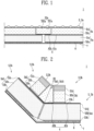
- FIG. 1 is a partial cross-sectional view of a flat portion for describing a liquefied gas storage tank according to a first embodiment of the present disclosure
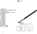
- FIG. 2 is a cross-sectional view of a corner portion for describing the liquefied gas storage tank according to the first embodiment of the present disclosure
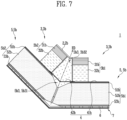
- FIG. 3 is a diagram illustrating structural analysis results for the corner portion of the liquefied gas storage tank according to the first embodiment of the present disclosure
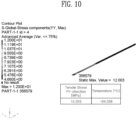
- FIG. 4 is a diagram illustrating other structural analysis results for the corner portion of the liquefied gas storage tank according to the first embodiment of the present disclosure.
- a ship provided with a liquefied gas storage tank 1 as described below is a concept that encompasses off-shore structures configured to float at a certain point on the sea and perform specific tasks in addition to commercial ships that transport cargo from an origin to a destination.
- the liquefied gas storage tank 1 may include any type of tank for storing liquefied gas.
- the liquefied gas storage tank 1 disposed on a ship may store liquefied gas such as LNG, which is a cryogenic material (at a temperature of about -160°C to -170°C), and may include a flat structure and a corner structure.
- liquefied gas such as LNG, which is a cryogenic material (at a temperature of about -160°C to -170°C)
- lateral walls in the front-rear direction, a floor between the lateral walls, vertical walls, and a ceiling of the liquefied gas storage tank 1 may correspond to a flat structure.
- a structure in which the lateral walls, the floor, the vertical walls, and the ceiling of the liquefied gas storage tank 1 meet may correspond to a corner structure.
- the corner structure may include an obtuse-angled corner structure or a right-angled corner structure.
- the flat structure of the liquefied gas storage tank 1 as shown in FIG. 1 may be made of a combination of a plurality of flat blocks
- the corner structure of the liquefied gas storage tank 1 as shown in FIG. 2 may be made of a combination of a plurality of corner blocks.
- the plurality of flat blocks may be connected to the plurality of corner blocks in the corner portion of the liquefied gas storage tank 1.
- the liquefied gas storage tank 1 may be configured to include a primary barrier 2 in contact with liquefied gas, the primary insulating wall 3 disposed on the outside of the primary barrier 2, a secondary barrier 4 disposed on the outside of the primary insulating wall 3, and the secondary insulating wall 5 disposed on the outside of the secondary barrier 4.
- the liquefied gas storage tank 1 may be supported on a hull 7 by a mastic 6 disposed between the secondary insulating wall 5 and the hull 7.
- the primary barrier 2 may include a flat primary barrier 2a of the flat block and a corner primary barrier 2b of the corner block
- the primary insulating wall 3 may include a flat primary insulating wall 3a of the flat block and a corner primary insulating wall 3b of the corner block
- the secondary barrier 4 may include a flat secondary barrier 41a of the flat block and a corner secondary barrier 41b of the corner block
- a secondary insulation wall 5 may include a flat secondary insulation wall 5a of the flat block and a corner secondary insulation wall 5b of the corner block.
- the secondary barrier 4 of the flat block and the corner block may include the flat secondary barriers 41a disposed adjacent to each other or a flat connecting barrier 42a or corner connecting barriers 42b connecting adjacent corner secondary barriers 41b.
- the liquefied gas storage tank 1 may need to optimize the thicknesses of the primary insulating wall 3 and the secondary insulating wall 5 in order to optimize the insulating performance and storage capacity.
- a total sum of the thickness of the primary insulating wall 3 and the thickness of the secondary insulating wall 5 may be in the range of 250 mm to 500 mm, and in this embodiment, the thickness of the primary insulating wall 3 and the thickness of the secondary insulating wall 5 in the flat block and the corner block may be the same as or similar to each other.
- the thickness of the primary insulating wall in the flat block and the corner block is about 1/3 times thinner than the thickness of the secondary insulating wall.
- the present embodiment configures the thickness of the primary insulating wall 3 and the thickness of the secondary insulating wall 5 in the flat block and the corner block to be the same as or similar to each other, the reason for which will be described below.
- the flat portion of the liquefied gas storage tank 1 includes a combination of a plurality of flat blocks, and it should be noted in advance that the configuration of the flat block of the liquefied gas storage tank 1 as described below applies the same not only to the first embodiment but also to the second embodiment to the eighth embodiment.
- the flat block of the liquefied gas storage tank 1 may be disposed on a flat portion on a first surface or a second surface at different angles forming a storage space for storing liquefied gas, and may include the flat primary insulating wall 3a disposed on the outside of the flat primary barrier 2a and securing the flat primary barrier 2a made of a metal material, the flat secondary barrier 41a disposed on the outside of the flat primary insulating wall 3a, and a flat secondary insulating wall 5a disposed on the outside of the flat secondary barrier 41a.
- the flat primary barrier 2a may be disposed on a flat portion on the first surface or the second surface at different angles to form a storage space for storing liquefied gas, which is a cryogenic material, and may be made of a metal material.
- the metal material may be a stainless steel material, but is not limited thereto.
- the flat primary barrier 2a may prevent leakage of liquefied gas to the outside in conjunction with the flat secondary barrier 41a.
- the flat primary barrier 2a may be fixedly coupled to an upper portion of the flat primary insulating wall 3a by a metal strip (not shown), and may be disposed to be in direct contact with liquefied gas, which is a cryogenic material stored in the liquefied gas storage tank 1.
- the flat primary barrier 2a seals the flat primary insulating wall 3a and the corner primary barrier 2b as shown in FIG. 2 when the flat block and the corner block as shown in FIG. 2 are adjacently connected to each other.
- the flat primary insulating wall 3a may be designed to withstand an impact from the outside or an impact caused by sloshing of liquefied gas from the inside while blocking heat intrusion from the outside, and may be disposed between the flat primary barrier 2a and the flat secondary barrier 41a.
- the flat primary insulating wall 3a may have a structure in which a flat primary plywood 31a and a flat primary insulation material 32a are sequentially stacked toward the outside of the flat primary barrier 2a, and a sum of the thickness of the flat primary plywood 31a and the thickness of the flat primary insulation material 32a may be, for example, in range of 160 mm to 250 mm, but is not limited thereto.
- the flat primary plywood 31a may be disposed between the flat primary barrier 2a and the flat primary insulation material 32a.
- the flat primary insulation material 32a is to be formed of a material having excellent thermal insulation performance as well as excellent mechanical strength so as to withstand the impact from the outside or sloshing of the liquefied gas from the inside while blocking the intrusion of heat from the outside.
- the flat primary insulation material 32a may be formed of polyurethane foam between the flat primary plywood 31a and the flat secondary barrier 4a, and may account for most of the thickness of the flat primary insulating wall 3a.
- the flat primary heat insulating wall 3a may be a part of the flat block with the flat secondary barrier 41a and the flat secondary insulating wall 5a, and the flat primary heat insulating wall 3a constituting the flat block may have a width smaller than the width of the flat secondary insulating wall 5a, which is another configuration for the flat block. Consequently, a portion of the flat secondary barrier 41a may be exposed on both sides of the flat primary insulating wall 3a.
- a flat connection insulating wall 33a may be disposed in a space portion between the adjacently disposed flat primary insulating walls 3a, that is, the space portion where the flat secondary barrier 41a is exposed.
- the flat connection insulating wall 33a may be disposed between the adjacent flat primary insulating walls 3a when the flat blocks are disposed adjacent to each other.
- the flat connection insulating wall 33a may be provided as a stack of the flat connection plywood 331a, which is the same as or similar to the flat primary insulation wall 3a, and the flat connection insulation material 332a, and may have the same or similar thickness to the flat primary insulating wall 3a.
- the flat connection insulating wall 33a may seal the space portion formed between the neighboring flat secondary insulating walls 5a with the flat connection barrier 42a when arranging a plurality of flat blocks adjacent to each other while also serving to block the intrusion of heat from the outside.
- the flat secondary barrier 41a may be disposed between the flat primary insulating wall 3a and the flat secondary insulating wall 5a, and may be configured to prevent leakage of liquefied gas to the outside in conjunction with the flat primary barrier 2a.
- the flat secondary barrier 41a is a part of the flat block together with the flat primary insulating wall 3a and the flat secondary insulating wall 5a, and may be connected by a flat connection barrier 42a when flat blocks are disposed adjacently.
- the flat connection barrier 42a may connect the neighboring flat secondary barriers 41 exposed to the outside when the flat blocks are disposed adjacently, and the flat connection insulating wall 33a may be disposed thereon.
- the flat secondary insulating wall 5a together with the flat primary insulating wall 3a and the flat connection insulating wall 33a, may be designed to withstand an impact from an external shock or liquefied gas sloshing from the inside while blocking heat intrusion from the outside.
- the flat secondary insulating wall 5a may be disposed between the flat secondary barrier 4a and the hull 7, and may include a flat secondary insulation material 51a and a flat secondary plywood 52a.
- the flat secondary insulating wall 5a may have a structure in which a flat secondary insulation material 51a and a flat secondary plywood 52a are sequentially stacked toward the outside of the flat secondary barrier 41a, and a sum of the thickness of the flat secondary insulation material 51a and the thickness of the flat secondary plywood 52a may be, for example, the same as or similar to the thickness of the flat primary insulating wall 3a such as in the range of 150 mm to 240 mm, but is not limited thereto.
- the flat secondary insulation material 51a may be made of a material having excellent thermal insulation performance and excellent mechanical strength so as to withstand an impact from the outside or an impact caused by liquefied gas sloshing from the inside while blocking heat intrusion from the outside.
- the flat secondary insulation material 51a may be formed of polyurethane foam between the flat secondary barrier 41a and the flat secondary plywood 52a, and accounts for most of the thickness of the flat secondary insulating wall 5a.
- the flat secondary plywood 52a may be disposed between the flat secondary insulation material 51a and the hull 7.
- the flat connection insulating wall 33a encompassed by the flat primary insulating wall 3a may be configured to have the same or similar thickness to the thickness of the flat secondary insulating wall 5a.
- the flat connection insulation material 332a of the flat connection insulation wall 33a may have a thickness of 90% to 110% of the flat secondary insulation material 51a such that the flat connection insulation material 332a of the flat connection insulation wall 33a has the same or similar thickness to that of the flat secondary insulation material 51a.
- the thickness of the flat primary insulating wall 3a and the thickness of the flat secondary insulating wall 5a in the flat block were configured to be the same or similar, compared to the liquefied gas storage tank of the related art where the thickness of the primary insulating wall in the flat block is about 1/3 thinner than the thickness of the secondary insulating wall. This is to prevent damages due to low-temperature stress of the flat secondary heat insulating wall 41a.
- the flat secondary barrier 41a and the flat secondary insulating wall 5a have a difference in the amount of selfcontraction depending on the temperature to which they are exposed.
- the thickness of the flat connection insulating wall 33a decreases, it may be significantly affected by the cooling and heating of the cryogenic liquefied gas.
- the amount of shrinkage itself may increase, resulting in a problem with the increased risk of damage to the flat secondary barrier 41a because stress at low temperature increases. In particular, this problem may occur frequently in the flat connection barrier 42a that interconnects the flat secondary barrier 41a below the flat connection insulation wall 33a by bonding or the like.
- the flat connection barrier 42a may be connected to the flat secondary barrier 41a of the plurality of flat blocks having both ends adjacent to each other. This is because both ends of the flat connection barrier 42a may be deformed to move away from or move closer to each other as the flat secondary heat insulating wall 5a of the flat block contracts.
- the present embodiment reduces the cryogenic burden on the flat secondary barrier 41a as well as the flat connection barrier 42a in particular by configuring the same or similar thicknesses for the flat primary insulating wall 3a and the flat secondary insulating wall 5a encompassing the flat connection insulating wall 33a.
- the amount of shrinkage itself may decrease, thereby reducing stress at the low temperature.
- the thickness of the insulating wall 5a becomes relatively thin compared to the conventional one, the amount of shrinkage itself is reduced, and thus the stress at low temperature is reduced. As a result, the risk of damages to the secondary barrier 4 in the portion where the plurality of flat blocks are disposed adjacent to each other may become relatively lower than that of the related art.
- the corner portion of the liquefied gas storage tank 1 may be formed of a combination of a plurality of corner blocks.
- the corner portion of the liquefied gas storage tank 1 is described below with an example of an obtuse-angled corner structure forming an angle of 135 degrees, but is not limited to such degree.
- the corner block of the liquefied gas storage tank 1 may be disposed at a corner portion where the first and second surfaces at different angles form a storage space for accommodating the liquefied gas, and may include a corner primary insulating wall 3b securing the corner primary barrier 2b made of metal and disposed on the outside of the corner primary barrier 2b, a corner secondary barrier 41b disposed on the outside of the corner primary insulating wall 3b, and a corner secondary insulating wall 5b disposed on the outside of the corner secondary barrier 41b.
- the corner primary insulating wall 3b may further include an inner bent portion 3b3.
- the corner primary barrier 2b may be disposed at a corner portion where the first surface or the second surface at different angles meet to form an accommodating space for accommodating liquefied gas, which is a cryogenic material, and may be made of a metal material.
- the corner primary barrier 2b may prevent leakage of liquefied gas to the outside in conjunction with the corner secondary barrier 41b.
- the corner primary barrier 2b may be fixedly coupled to the corner primary insulating wall 3b by a barrier fixing member installed in various ways such as bonding or bolting to an upper end of the corner primary insulating wall 3b so as to be disposed in direct contact with liquefied gas, which is a cryogenic material stored in the liquefied gas storage tank 1.
- a barrier fixing member installed in various ways such as bonding or bolting to an upper end of the corner primary insulating wall 3b so as to be disposed in direct contact with liquefied gas, which is a cryogenic material stored in the liquefied gas storage tank 1.
- the corner primary barrier 2b described below may be used in a sense including a barrier fixing member or the like.
- This corner primary barrier 2b may seal the corner primary insulating wall 3b and the flat primary barrier 2a as shown in FIG. 1 when the corner block and the flat block as shown in FIG. 1 are adjacently connected to each other, and the corner primary barrier 2b may be secured to an inner primary plywood 31b of an inner first fixing portion 3b1 and the inner primary plywood 31b of an inner second fixing portion 3b2, and may be provided to be bend at a predetermined angle, for example, 135 degrees from an inner surface of an insulation material 3b31 of the inner bent portion 3b3.
- the corner primary insulating wall 3b may be designed to withstand an impact from the outside or an impact caused by liquefied gas sloshing from the inside while blocking heat intrusion from the outside, and may be disposed between the corner primary barrier 2b and the corner secondary barrier 41b.
- the corner primary insulating walls 3b may be disposed on the inside of the first and second surfaces, respectively, and may include the inner first fixing portion 3b1 and the inner second fixing portion 3b2 including the inner primary plywood 31b, corner primary insulation material 32b, and outer primary plywood 33b sequentially stacked toward the outside of the corner primary barrier 2b.
- the inner first fixing portion 3b1 may be secured to an outer first fixing portion 5b1 and disposed on the inside of the first surface
- the inner second fixing portion 3b2 may be secured to an outer second fixing portion 5b2 and provided on the inside of the second surface.
- corner primary insulating walls 3b may include an inner bent portion 3b3 configured by filling an insulation material 3b31 between the inner first fixing portion 3b1 and the inner second fixing portion 3b2.
- a sum of the thickness of the inner primary plywood 31b, the thickness of the corner primary insulation material 32b, and the thickness of the outer primary plywood 33b may be the same as the thickness of the flat primary insulating walls 3a (e.g. a thickness of 160 mm to 250 mm) as described above.
- the inner primary plywood 31b may be disposed between the corner primary barrier 2b and the corner primary insulation material 32b.
- the primary insulating walls 3 in the flat block and the corner block may be formed to be thicker than the thickness of the primary insulating walls of the related art, it may be possible to reduce the thickness of the inner primary plywood 31b constituting the corner primary insulating walls 3b of the corner block, and a remaining portion of the thickness may be replaced with the corner primary insulation material 32b made of polyurethane foam.
- the inner primary plywood 31b of this embodiment may have a thickness of 20 mm to 80 mm.
- the inner first and second fixing portions 3b1, 3b2 for holding the barrier fixing member to which the corner primary barrier 2b is secured in the corner block from a combination with the corner primary insulation material 32b of polyurethane foam in place of only plywood having a thickness of about 92mm as in the related art, insulation performance may be improved, and related weights and costs may be reduced compared to the related art consisting only of plywood.
- the corner primary insulation material 32b may be disposed between the inner primary plywood 31b and the outer primary plywood 33b, and may be formed of high-density polyurethane foam, which is a material having excellent insulation performance and excellent mechanical strength so as to withstand an impact from the outside or an impact caused by liquefied gas sloshing from the inside while blocking heat intrusion from the outside.
- the outer primary plywood 33b may be disposed between the corner primary insulation material 32b and the corner secondary barrier 41b, and may be secured to the corner secondary barrier 41b.
- the outer primary plywood 33b may be formed to have a thickness of 6.5 mm to 15 mm.
- the corner primary insulating wall 3b of this embodiment may be configured to have a structure in which the inner primary plywood 31b, the corner primary insulation material 32b, and the outer primary plywood 33b are sequentially stacked. Therefore, the high strength inner primary plywood 31b and the outer primary plywood 33b may hold thermal contraction of the corner primary insulation material 32b such that the thermal contraction of the corner primary insulation material 32b is not directly applied to the secondary barriers 4, 41b, and 42b between the outer first and second fixing portions 5b1, 5b2, and it may be also possible to easily control the tolerance of the inner primary plywood 31b and the outer primary plywood 33b sensitive to humidity by providing the corner primary insulation material 32b as an intermediate layer.
- Each of the inner first and second fixing portions 3b1 and 3b2 consisting of the corner primary insulating walls 3b is secured to each of the outer first and second fixing portions 5b1, 5b2 consisting of the corner secondary barrier 41b and the corner secondary insulating walls 5b, and each of these inner first and second fixing portions 3b1 and 3b2 may have a width smaller than that of each of the outer first and second fixing portions 5b1 and 5b2.
- the inner bent portion 3b3 may be formed in a space portion between the adjacent inner first and second fixing portions 3b1 and 3b2, that is, in the space portion where the corner secondary barrier 41b is exposed.
- the inner bent portion 3b3 may be configured by filling it with the insulation material 3b31.
- the insulation material 3b31 of the inner bent portion 3b3 may be a low-density polyurethane foam, and the secondary barrier 4 in which the corner secondary barrier 41b and the corner connection barrier 42b are stacked may be disposed on the outer surface bent at a predetermined angle, for example, an angle of 135 degrees.
- the insulation material 3b31 of the inner bent portion 3b3 may serve to block the heat intrusion from the outside by sealing the space portion formed between the adjacently disposed outer first and second fixing portions 5b1 and 5b2 in conjunction with the corner connection barrier 42b when the plurality of corner blocks are disposed adjacently.
- the corner secondary barrier 41b may be disposed on the outside of the corner primary insulating walls 3b.
- the corner secondary barrier 41b may be disposed between the corner primary insulating walls 3b and the corner secondary insulating walls 5b, and may be configured to prevent leakage of liquefied gas to the outside in conjunction with the corner primary barrier 2b.
- the corner secondary barrier 41b is a part of the configuration of the corner block together with the corner primary insulating walls 3b and the corner secondary insulating walls 5b, and the neighboring corner secondary barrier 41b between the outer first and second fixing portions 5b1 and 5b2 may be connected by a corner connecting barrier 42b when corner blocks are disposed adjacently.
- the corner connection barrier 42b may connect the neighboring corner secondary barriers 41b exposed to the outside when the corner blocks are disposed adjacently, and the insulation material 3b31 of the inner bent portion 3b3 may be disposed thereon so as to seal the space formed between the insulation material 3b31 of the inner bent part 3b3 and the outer first and second fixing portions 5b1 and 5b2 disposed adjacent to each other, thereby serving to block heat intrusion from the outside.
- the corner connecting barrier 42b may be formed to extend not only between the inner first and second fixing portions 3b1 and 3b2, but also extend to a length overlapping with at least the inner first and second fixing portions 3b1 and 3b2.
- the secondary barrier 4 in which the corner secondary barrier 41b and the corner connecting barrier 42b are stacked may be disposed to be bent.
- the corner secondary insulating walls 5b may be disposed on the outside of the corner secondary barrier 41b.
- the corner secondary insulating wall 5b may be designed to withstand an impact from the outside or an impact caused by liquefied gas sloshing from the inside while blocking heat intrusion from the outside in conjunction with the insulation material 3b31 of the inner bent portion 3b3 and the corner primary insulating walls 3b.
- the corner secondary insulation wall 5b may be disposed between the corner secondary barrier 4b and the hull 7, and may be configured to include the inner secondary plywood 51b, the corner secondary insulation material 52b, and the outer secondary plywood 53b.
- the corner secondary insulating walls 5b may be secured to the inside of the first and second surfaces, respectively, and may include the outer first fixing portion 5b1 and the outer second fixing portion 5b2 including the inner secondary plywood 51b, the corner secondary insulation material 52b, the outer secondary plywood 53b sequentially stacked toward the outside of the corner secondary barrier 2b.
- outer first fixing portion 5b1 may be secured to the inside of the first surface
- outer second fixing portion 5b2 may be secured to the inside of the second surface
- the side on which the outer first fixing portion 5b1 secured to the first surface and the outer second fixing portion 5b2 secured to the second surface face each other may be disposed to be inclined in the direction ED of evenly dividing the corner portion.
- the corner portion is described to be equally divided, but it is not limited thereto, and as the division may not be equal depending on the position of the corner, the side may also be disposed to be inclined in the direction ED of unevenly dividing the corner portion.
- the thickness of this corner secondary insulating walls 5b may have a thickness that is a sum of the thickness of the inner secondary plywood 51b, the thickness of the corner secondary insulation material 52b, and the thickness of the outer secondary plywood 53b, which is the same as that of the flat secondary insulating walls 5a (e.g., 150 mm to 240 mm) as described above.
- the inner secondary plywood 51b may be disposed between the corner secondary barrier 2b and the corner secondary insulation material 51b, and may secure the corner secondary barrier 2b.
- the inner secondary plywood 51b may be formed to have a thickness of 6.5 mm to 15 mm.
- the corner secondary insulation material 52b may be formed of a material having excellent thermal insulation performance and excellent mechanical strength so as to withstand an impact from the outside or an impact caused by liquefied gas sloshing from the inside while blocking heat intrusion from the outside.
- the corner secondary insulation material 52b may be formed of polyurethane foam between the inner secondary plywood 51b and the outer secondary plywood 53b, accounting for most of the thickness of the corner secondary insulating walls 5b.
- the outer secondary plywood 53b may be disposed between the corner secondary insulation material 52b and the hull 7.
- the outer secondary plywood 53b may be formed to have a thickness of 6.5 mm to 25 mm.
- the secondary barrier 4 in the flat block as well as the corner block may move toward the hull 7 side, thereby increasing the radius of curvature.
- the radius of curvature of the secondary barrier 4 increases at the corner portion, the length of the portion where the secondary barrier 4 is not attached to the secondary insulating walls 5 also increases.
- the length of the non-adhesive portion may be, for example, 0 mm to 100 mm, preferably 50 mm to 100 mm.
- the secondary barrier 4 in the obtuse-angled corner structure of the present disclosure may have reduced low-temperature stress applied thereon compared to the obtuse-angled corner structure of the primary insulating walls 3 formed with a relatively thin thickness.
- the non-adhesive portion increases, it is also easy to absorb hull deformations.
- heat transfer analysis was performed at 20°C at the hull position and 163°C at the primary barrier, and structural analysis was carried out using a resulting temperature distribution.
- the thickness of the primary insulating walls is about 1/3 times thinner than that of the secondary insulating walls
- the fixing members corresponding to the inner first and second fixing portions 3b1 and 3b2 consist of only plywood
- the length of the non-adhesive portion is 50 mm
- a value of the stress of the bent portion of the secondary barrier in the YY direction was about 66.8984 MPa
- the temperature was about -135.857 °C.
- the stress value in the YY direction obtained as a result of structural analysis corresponds to a stress value at the corner, and the lower the value is, there is less stress.
- the temperature corresponds to a temperature at the corner, and the higher the temperature, the less stress (represents a value changed after installation at room temperature of 25°C).
- FIG. 3 shows results of structural analysis of the temperature distribution and the stress value in the YY direction of the secondary barriers 4, 41b, 42b in the bent portion where the outer first and second fixing portions 5b1 and 5b2 face each other when the length of the non-adhesive portion in this embodiment is 50 mm.
- the stress value in the YY direction was 37.155 MPa, and the temperature was -57.940 °C.
- FIG. 4 shows results of structural analysis of the temperature distribution and the stress value in the YY direction of the secondary barriers 4, 41b, 42b in the bent portion where the outer first and second fixing portions 5b1 and 5b2 face each other when the length of the non-adhesive portion of this embodiment is 97 mm.
- the stress value in the YY direction was 12.084 MPa, and the temperature was -59.025 °C.
- the inner first and second fixing portions 3b1, 3b2 for holding the barrier fixing member to which the corner primary barrier 2b is secured in the corner block from a combination with the insulation material 3b31 of polyurethane foam instead of only plywood, insulation performance may be improved, and related weights and costs may be reduced compared to those of the related art which consist only of plywood.
- the corner primary insulating wall 3b of the corner block connected to the flat primary insulating wall 3a of the flat block may be configured to have the same or similar thickness to that of the corner secondary insulating walls 5b of the corner block connected to the flat secondary insulating walls 5a of the flat block, thereby increasing the thickness of the corner primary insulating walls 3b compared to the related art (however, the thickness of the corner secondary insulation wall 5b is sufficient to maintain the mechanical strength at a certain level).
- the thickness of the corner primary insulating walls 3b may be configured to be relatively thicker than the related art so that the length of the non-adhesive portion of the secondary barriers 4, 41b, 42b to the corner secondary insulating wall 5b is increased.
- the secondary barriers 4, 41b, 42b due to the increased flexibility of the secondary barriers 4, 41b, 42b, it is possible to further lower the probability of damages to the secondary barriers 4, 41b, 42b, and the secondary barriers 4, 41b, 42b may easily absorb hull deformations while further reducing the low-temperature stress.
- FIG. 5 is a cross-sectional view of the corner portion for describing a liquefied gas storage tank according to a second embodiment of the present disclosure
- FIG. 6 is a diagram illustrating structural analysis results for the corner portion of the liquefied gas storage tank according to the second embodiment of the present disclosure.
- the flat structure of the liquefied gas storage tank 1 of this embodiment may consist of a combination of a plurality of flat blocks as shown in FIG. 1
- the corner structure of the liquefied gas storage tank 1 may consist of a combination of a plurality of corner blocks as shown in FIG. 5
- the plurality of flat blocks may be connected to the plurality of corner blocks at the corner portion of the liquefied gas storage tank 1.
- the configuration of the flat blocks is the same as or similar to the configuration as described above with reference to FIG. 1 .
- the flat block of the liquefied gas storage tank 1 may be disposed on a flat portion on a first surface or a second surface at different angles forming a storage space for accommodating liquefied gas, and may include the flat primary insulating wall 3a disposed on the outside of the flat primary barrier 2a and securing the flat primary barrier 2a made of a metal material, the flat secondary barrier 41a disposed on the outside of the flat primary insulating wall 3a, and a flat secondary insulating wall 5a disposed on the outside of the flat secondary barrier 41a.
- the liquefied gas storage tank 1 may be configured to include the primary barrier 2 in contact with the liquefied gas, the primary insulating wall 3 disposed on the outside of the primary barrier 2, the secondary barrier 4 disposed on the outside of the primary insulating wall 3, and the secondary insulating wall 5 disposed on the outside of the secondary barrier 4.
- the liquefied gas storage tank 1 may be supported by the mastic 6 disposed between the secondary insulating wall 5 and the hulls 7.
- the primary barrier 2 may include the flat primary barrier 2a of the flat block and the corner primary barrier 2b of the corner block
- the primary insulating wall 3 may include the flat primary insulating wall 3a of the flat block and the corner primary insulating wall 3b of the corner block
- the secondary barrier 4 may include the flat secondary barrier 41a of the flat block and the corner secondary barrier 41b of the corner block
- the secondary insulating wall 5 may include the flat secondary insulating wall 5a of the flat block and the corner secondary insulation wall 5b of the corner block.
- the thickness of the primary insulating wall 3 and the thickness of the secondary insulating wall 5 in the flat block and the corner block may be configured the same as or similar to each other.
- the secondary barrier 4 of the flat block and the corner block when arranging a plurality of flat blocks or a plurality of corner blocks adjacently, may further include a flat connection barrier 42a or a corner connection barrier 42b for connecting adjacently disposed flat secondary barriers 41a or adjacently disposed corner secondary barriers 41b.
- the corner portion of the liquefied gas storage tank 1 may consist of a combination of a plurality of corner blocks.
- the corner structure of the liquefied gas storage tank 1 as described below may be an obtuse-angled corner structure forming a predetermined angle, for example, 135 degrees.
- the corner block of the liquefied gas storage tank 1 may be disposed at the corner portion where the first surface and the second surface at different angles forming a storage space for accommodating liquefied gas meet, and the corner block may include the corner primary insulating wall 3b disposed on the outside of the corner primary barrier 2b and securing the corner primary barrier 2b made of a metal material, the corner secondary barrier 41b disposed on the outside of the corner primary insulating wall 3b, and the corner secondary insulating wall 5b disposed on the outside of the corner secondary barrier 41b.
- the corner primary barrier 2b may be disposed at the corner portion where the first surface or the second surface at different angles meet to form an accommodating space for accommodating liquefied gas, which is a cryogenic material, and the corner primary barrier 2b may be made of a metal material.
- the corner primary barrier 2b may prevent leakage of liquefied gas to the outside in conjunction with the corner secondary barrier 41b.
- the corner primary barrier 2b of the present embodiment is basically the same as or similar to the first embodiment as described above, and thus detailed description thereof will be omitted here.
- the corner primary barrier 2b of this embodiment may have a different bending angle as the configuration of the corner primary insulating wall 3b is different from that of the first embodiment, which will be discussed below when describing the corner primary insulating wall 3b.
- the corner primary insulating wall 3b may be designed to withstand an impact from the outside or an impact caused by liquefied gas sloshing from the inside while blocking heat intrusion from the outside, and may be disposed between the corner primary barrier 2b and the corner secondary barrier 41b.
- the configuration of the corner primary insulating wall 3b of this embodiment is the same as or similar to that of the first embodiment except that the outer primary plywood 33b is omitted, and the placement of the inner bent portion 3b3 configured by filling the insulation material 3b31. Therefore, the differences therebetween will be mainly discussed below.
- the corner primary insulating wall 3b may be provided on the inside of the first surface and the second surface, respectively, and may include the inner first fixing portion 3b1 and the inner second fixing portion 3b2 configured to include the inner first plywood 31b and the corner primary insulation material 32b stacked sequentially toward the outside of the corner primary barrier 2b.
- the inner primary plywood 31b and the corner primary insulation material 32b of this embodiment may be the same as or similar to those of the first embodiment as described above, and thus detailed descriptions thereof are omitted to avoid redundancy.
- the inner first fixing portion 3b1 may be disposed on the inside of the first surface by being secured to the outer first fixing portion 5b1, and the inner second fixing portion 3b2 may be disposed on the inside of the second surface by being secured to the outer second fixing portion 5b2.
- corner primary insulating wall 3b may include an inner intermediate fixing portion 3b12 provided between the inner first fixing portion 3b1 and the inner second fixing portion 3b2.
- the inner intermediate fixing portion 3b12 may include a corner intermediate insulation material 32b12 secured to the corner connecting barrier 42b connecting the neighboring corner secondary barriers 41b, and an inner intermediate plywood 31b12 disposed on the inside of the corner intermediate insulation material 32b12 and to which the corner primary barrier 2b is secured.
- the inner intermediate plywood 31b12 may be parallel to the direction perpendicular to the evenly dividing direction ED when the corner portion is evenly divided. However, of course, the inner intermediate plywood 31b12 may not be parallel to the direction perpendicular to the direction ED for dividing the corner portion when unevenly dividing the corner portion.
- the corner intermediate insulation material 32b12 may be formed of the same or similar material to the corner primary insulation material 32b.
- the corner intermediate insulation material 32b12 may be formed of high-density polyurethane foam.
- This corner intermediate heat insulation material 32b12 when arranging a plurality of corner blocks adjacently, may seal the space portion formed between the adjacently disposed outer first and second fixing portions 5b1 and 5b2 in conjunction with the corner connection barrier 42b, serving to block heat intrusion from the outside.
- the corner connecting barrier 42b may be formed to extend not only between the inner first and second fixing portions 3b1 and 3b2, but also extend to a length overlapping with at least the inner first and second fixing portions 3b1 and 3b2.
- the corner primary barrier 2b may be secured to the inner primary plywood 31b of the inner first fixing portion 3b1, the inner intermediate plywood 31b12 of the inner intermediate fixing portion 3b12, and the inner primary plywood 31b of the inner second fixing portion 3b2 by disposing the inner intermediate plywood 31b12 between the inner first fixing portion 3b1 and the inner second fixing portion 3b2, and the corner primary barrier 2b may be bent in an angle range of 150 degrees to 160 degrees between the inner first fixing portion 3b1 and the inner intermediate fixing portion 3b12, and between the inner intermediate fixing portion 3b12 and the inner second fixing portion 3b2.
- the present embodiment may reduce the bending angle of the corner primary barrier 2b by the inner intermediate fixing portion 3b12, thereby reducing the burden of sloshing in the corner primary barrier 2b and increasing the mechanical strength of the corner portion.
- the corner secondary barrier 41b may be disposed between the corner primary insulating wall 3b and the corner secondary insulating wall 5b, and when the corner blocks are adjacently disposed, the corner secondary barrier 41b neighboring between the outer first and second fixing portions 5b1 and 5b2 may be connected by the corner connection barrier 42b, serving to prevent leakage of liquefied gas to the outside in conjunction with the corner primary barrier 2b.
- the corner secondary barrier 41b of the present embodiment is the same as or similar to that of the first embodiment as described above, and detailed descriptions thereof are omitted to avoid redundancy.
- the corner secondary insulation wall 5b may be configured to include the inner secondary plywood 51b, corner secondary insulation material 52b, and outer secondary plywood 53b.
- the corner secondary insulating wall 5b may be secured to the inside of the first side and the second side, respectively, and may include the outer first fixing portion 5b1 and the outer second fixing portion 5b2 configured to include the inner secondary plywood 51b, the corner secondary insulation material 52b, and the outer secondary plywood 53b stacked sequentially toward the outside of the corner secondary barrier 2b.
- FIG. 6 shows results of structural analysis of the temperature distribution and the stress value in the YY direction of the secondary barriers 4, 41b, 42b in the bent portion where the outer first and second fixing portions 5b1 and 5b2 face each other.
- the stress value was 10.982 MPa, and the temperature was -67.914 °C.
- FIG. 7 is a cross-sectional view of a corner portion for describing a liquefied gas storage tank according to a third embodiment of the present disclosure
- FIG. 8 is a diagram illustrating structural analysis results for the corner portion of the liquefied gas storage tank according to the third embodiment of the present disclosure.
- the flat structure of the liquefied gas storage tank 1 of this embodiment may consist of a combination of a plurality of flat blocks as shown in FIG. 1 described above, and the corner structure of the liquefied gas storage tank 1 may consist of a combination of a plurality of corner blocks as shown in FIG. 7 .
- the flat blocks may be connected to the plurality of corner blocks in the corner portion of the liquefied gas storage tank 1.
- the configuration of the flat block is the same as or similar to the configuration as described above with reference to FIG. 1 .
- the flat block of the liquefied gas storage tank 1 may be disposed on a flat portion on a first surface or a second surface at different angles forming a storage space for storing liquefied gas, and may include the flat primary insulating wall 3a disposed on the outside of the flat primary barrier 2a and securing the flat primary barrier 2a made of a metal material, the flat secondary barrier 41a disposed on the outside of the flat primary insulating wall 3a, and the flat secondary insulating wall 5a disposed on the outside of the flat secondary barrier 41a.
- the liquefied gas storage tank 1 may be configured to include the primary barrier 2 in contact with the liquefied gas, the primary insulating wall 3 disposed on the outside of the primary barrier 2, the secondary barrier 4 disposed on the outside of the primary insulating wall 3, and the secondary insulating wall 5 disposed on the outside of the secondary barrier 4.
- the liquefied gas storage tank 1 may be supported on the hull 7 by the mastic 6 disposed between the secondary insulating wall 5 and the hull 7.
- the primary barrier 2 may consist of the flat primary barrier 2a of the flat block and the corner primary barrier 2b of the corner block
- the primary insulating wall 3 may consist of the flat primary insulating wall 3a of the flat block and the corner primary insulating wall 3b of the corner block
- the secondary barrier 4 may consist of the flat secondary barrier 41a of the flat block and the corner secondary barrier 41b of the corner block
- the secondary insulating wall 5 may consist of the flat secondary insulating wall 5a of the flat block and the corner secondary insulation wall 5b of the corner block.
- the thickness of the primary insulating wall 3 and the thickness of the secondary insulating wall 5 in the flat block and the corner block may be the same as or similar to each other.
- the secondary barrier 4 of the flat block and the corner block may include the flat connection barrier 42a or the corner connection barrier 42b connecting the adjacently disposed flat secondary barriers 41a or the adjacently disposed corner secondary barriers 41b.
- the corner portion of the liquefied gas storage tank 1 may consist of a combination of a plurality of corner blocks.
- the corner structure of the liquefied gas storage tank 1 as described below may be an obtuse-angled corner structure forming a predetermined angle, for example, 135 degrees.
- the corner primary insulating wall 3b may also be positioned to expose the corner secondary barrier 41b constructed on the corner secondary insulating wall 5b at the center of the corner portion. Therefore, it is also possible to finish the exposed corner secondary barrier 41b by interconnecting with the corner connecting barrier 42b, or to stack the corner primary insulating wall 3b on top of the corner secondary barrier 41b/corner connecting barrier 42b after the construction of the corner connection barrier 42b to connect the adjacently disposed neighboring corner secondary barrier 41b.
- the corner connecting barrier 42b may be formed to extend not only between the inner first and second fixing portions 3b1 and 3b2, but also extend to a length overlapping with at least the inner first and second fixing portions 3b1 and 3b2.
- the corner block of the liquefied gas storage tank 1 may be disposed at the corner portion where the first surface and the second surface at different angles forming a storage space for accommodating liquefied gas meet, and the corner block may include the corner primary insulating wall 3b disposed on the outside of the corner primary barrier 2b and securing the corner primary barrier 2b made of a metal material, the corner secondary barrier 41b disposed on the outside of the corner primary insulating wall 3b, and the corner secondary insulating wall 5b disposed on the outside of the corner secondary barrier 41b.
- the corner primary barrier 2b may be disposed at the corner portion where the first surface or the second surface at different angles meet to form an accommodating space for accommodating liquefied gas, which is a cryogenic material, and may be made of a metal material.
- the corner primary barrier 2b may prevent leakage of liquefied gas to the outside in conjunction with the corner secondary barrier 41b.
- the corner primary insulating wall 3b may be designed to withstand an impact from the outside or an impact caused by liquefied gas sloshing from the inside while blocking heat intrusion from the outside, and may be disposed between the corner primary barrier 2b and the corner secondary barrier 41b.
- the configuration of the corner primary insulating wall 3b of this embodiment is the same as or similar to that of the first embodiment as described above except that the outer primary plywood 33b is omitted, and thus only differences therebetween are mainly described below.
- the corner primary insulating wall 3b may be disposed on the inside of the first and second surfaces, respectively, and may include the inner first fixing portion 3b1 and the inner second fixing portion 3b2 having the inner primary plywood 31b and the corner primary insulation material 32b sequentially stacked toward the outside of the corner primary barrier 2b.
- the inner primary plywood 31b and the corner primary insulation material 32b of this embodiment may be the same as or similar to those of the first embodiment as described above, and thus detailed descriptions thereof are omitted to avoid redundancy.
- the inner first fixing portion 3b1 may be disposed on the inside of the first surface by being secured to the outer first fixing portion 5b1, and the inner second fixing portion 3b2 may be disposed on the inside of the second surface by being secured to the outer second fixing portion 5b2.
- the corner primary heat insulating wall 3b may include the inner bent portion 3b3 configured by filling an insulation material 3b32 between the inner first fixing portion 3b1 and the inner second fixing portion 3b2.
- the insulation material 3b32 of the inner bent portion 3b3 of the present embodiment may be the same as or similar to that of the first embodiment as described above, and thus, detailed descriptions thereof are omitted to avoid redundancy.
- the corner secondary barrier 41b may be disposed between the corner primary insulating wall 3b and the corner secondary insulating wall 5b, and when the corner blocks are adjacently disposed, the corner secondary barrier 41b neighboring between the outer first and second fixing portions 5b1 and 5b2 may be connected by the corner connection barrier 42b, serving to prevent leakage of liquefied gas to the outside in conjunction with the corner primary barrier 2b.
- the corner secondary barrier 41b of the present embodiment may have basically the same or similar configuration to that of the first embodiment as described above.
- corner secondary barrier 41b encompassing the corner connection barrier 42b of this embodiment may have a different arrangement from that of the first embodiment as described above in terms of some configuration of the corner secondary insulating wall 5b, which will be discussed below when describing the corner secondary insulating wall 5b.
- the corner secondary Insulating wall 5b may be configured to include the inner secondary plywood 51b, the corner secondary insulation material 52b, and the outer secondary plywood 53b.
- the corner secondary insulating wall 5b may be secured to the inside of the first surface and the second surface, respectively, and may include the outer first fixing portion 5b1 and the outer second fixing portion 5b2 having the inner secondary plywood 51b, the corner secondary insulation material 52b, and the outer secondary plywood 53b stacked sequentially toward the outside of the corner secondary barrier 2b.
- the aforesaid outer first fixing portion 5b1 and the outer second fixing portion 5b2 may be disposed such that their side surfaces facing each other are inclined in the direction ED of evenly dividing the corner portion.
- the corner portion is described to be evenly divided, but it is not limited thereto, and they may be inclined in the direction ED of unevenly dividing the center portion.
- the outer first fixing portion 5b1 and the outer second fixing portion 5b2 may have a chamfer formed at the corner where they face each other.
- corner secondary heat insulating wall 5b may include the outer bent portion 5b3 including the insulation material 5b31 filled between the chamfered portions of the outer first fixing portion 5b1 and the outer second fixing portion 5b2.
- the insulation material 5b31 of the outer bent portion 5b3 may be a low-density polyurethane foam.
- the corner secondary barrier 41b encompassing the corner connection barrier 42b may be secured to the inner secondary plywood 51b of the outer first fixing portion 5b1, the insulation material 5b31 of the outer bent portion 5b3, and the inner secondary plywood 51b of the outer second fixing portion 5b2, and may be provided to bend at a predetermined angle, for example 135 degrees from the inside of the insulation material of the outer bent portion 5b3.
- chamfers may be formed at the corner where the outer first fixing portion 5b1 and the outer second fixing portion 5b2 respectively secured to the first and second surfaces at different angles face each other, and it is possible to further increase the thermal insulation performance at the corners using the low-density polyurethane foam by providing the insulation material 5b31 of the outer bent portion 5b3 made of low-density polyurethane foam in the chamfers.
- FIG. 8 shows results of structural analysis of the temperature distribution and the stress value in the YY direction of the secondary barriers 4, 41b, 42b in the bent portion where the outer first and second fixing portions 5b1 and 5b2 face each other.
- the stress value was 12.003 MPa, and the temperature was -64.358 °C.
- FIG. 9 is a cross-sectional view of a corner portion for describing a liquefied gas storage tank according to a fourth embodiment of the present disclosure
- FIG. 10 is a diagram illustrating structural analysis results for the corner portion of the liquefied gas storage tank according to the fourth embodiment of the present disclosure.
- the flat structure of the liquefied gas storage tank 1 of this embodiment may consist of a combination of a plurality of flat blocks as shown in FIG. 1
- the corner structure of the liquefied gas storage tank 1 may consist of a combination of a plurality of corner blocks as shown in FIG. 9 .
- the flat blocks may be connected to the plurality of corner blocks at the corner portion of the liquefied gas storage tank 1.
- the configuration of the flat block is the same as or similar to the configuration as described above with reference to FIG. 1 .
- the flat block of the liquefied gas storage tank 1 of this embodiment may be disposed at a flat portion on the first surface or the second surface at different angles forming a storage space for accommodating the liquefied gas, and may include the flat primary insulating wall 3a disposed on the outside of the flat primary barrier 2a and securing the flat primary barrier 2a made of a metal material, the flat secondary barrier 41a disposed on the outside of the flat primary insulating wall 3a, and the flat secondary insulating wall 5a disposed on the outside of the flat secondary barrier 41a.
- the liquefied gas storage tank 1 may be configured to include the primary barrier 2 in contact with the liquefied gas, the primary insulating wall 3 disposed on the outside of the primary barrier 2, the secondary barrier 4 disposed on the outside of the primary insulating wall 3, and the secondary insulating wall 5 disposed on the outside of the secondary barrier 4.
- the liquefied gas storage tank 1 may be supported by the mastic 6 on the hull 7 disposed between the secondary insulating wall 5 and the hull 7.
- the primary barrier 2 may include the flat primary barrier 2a of the flat block and a corner primary barrier 2b of the corner block
- the primary insulating wall 3 may consist of a flat primary insulating wall 3a of the flat block and a corner primary insulating wall 3b of the corner block
- the secondary barrier 4 may include the flat secondary barrier 41a of the flat block and the corner secondary barrier 41b of the corner block
- the secondary insulation wall 5 may consist of a flat secondary insulation wall 5a of the flat block and a corner secondary insulation wall 5b of the corner block.
- the thickness of the primary insulating wall 3 and the thickness of the secondary insulating wall 5 in the flat block and the corner block may be the same as or similar to each other.
- the secondary barrier 4 of the flat block and the corner block when arranging a plurality of flat blocks or a plurality of corner blocks adjacently, may include the flat connecting barrier 42a or the corner connecting barriers 42b connecting the adjacently disposed flat secondary barrier 41a or the adjacently disposed corner secondary barrier 41b.
- the corner portion of the liquefied gas storage tank 1 may consist of a plurality of corner blocks.
- the corner structure of the liquefied gas storage tank 1 as described below may be an obtuse-angled corner structure forming a predetermined angle, for example, 135 degrees.
- the corner primary insulating wall 3b may also be positioned to expose the corner secondary barrier 41b constructed on the corner secondary insulating wall 5b at the center of the corner portion. Therefore, it is also possible to finish the exposed corner secondary barrier 41b by interconnecting with the corner connecting barrier 42b, or to stack the corner primary insulating wall 3b on top of the corner secondary barrier 41b/corner connecting barrier 42b after the construction of the corner connection barrier 42b to connect the adjacently disposed neighboring corner secondary barrier 41b.
- the corner connecting barrier 42b may be formed to extend not only between the inner first and second fixing portions 3b1 and 3b2, but also extend to a length overlapping with at least the inner first and second fixing portions 3b1 and 3b2.
- the corner block of the liquefied gas storage tank 1 may be disposed at the corner portion where the first and second surfaces at different angles forming a storage space for accommodating the liquefied gas meet, and may include the corner primary insulating wall 3b securing the corner primary barrier 2b made of metal and disposed on the outside of the corner primary barrier 2b, the corner secondary barrier 41b disposed on the outside of the corner primary insulating wall 3b, and the corner secondary insulating wall 5b disposed on the outside of the corner secondary barrier 41b.
- the corner primary barrier 2b may be disposed at the corner portion where the first surface or the second surface at different angles meet, forming an accommodating space for accommodating liquefied gas, which is a cryogenic material, and may be made of a metal material.
- the corner primary barrier 2b may prevent leakage of liquefied gas to the outside in conjunction with the corner secondary barrier 41b.
- the corner primary barrier 2b of the present embodiment is basically the same as or similar to that of the first embodiment as described above, and detailed descriptions thereof are omitted herein.
- the corner primary insulating wall 3b may be designed to withstand an impact from the outside or an impact caused by liquefied gas sloshing from the inside while blocking heat intrusion from the outside, and may be disposed between the corner primary barrier 2b and the corner secondary barriers 41b.
- the configuration of the corner primary insulating wall 3b of this embodiment is the same as or similar to that of the first embodiment as described above except that the outer primary plywood 33b is omitted and the inner bent portion 3b3 has a different configuration, and thus only differences therebetween are mainly described below.
- the corner primary insulating wall 3b may be disposed on the inside of the first surface and the second surface, respectively, and may include the inner first fixing portion 3b1 and the inner second fixing portion 3b2 having the inner primary plywood 31b and the corner primary insulation material 32b stacked sequentially toward the outside of the corner primary barrier 2b.
- the inner primary plywood 31b and the corner primary insulation material 32b of this embodiment may be the same as or similar to those of the first embodiment as described above, and thus detailed descriptions thereof are omitted to avoid redundancy.
- the inner first fixing portion 3b1 may be disposed on the inside of the first surface by being secured to the outer first fixing portion 5b1, and the inner second fixing portion 3b2 may be disposed on the inside of the second surface by being secured to the outer second fixing portion 5b2.
- the corner primary insulating wall 3b may include an inner bent portion 3b3 including an outer insulation material 3b33 filled between the inner first fixing portion 3b1 and the inner second fixing portion 3b2, and disposed on the corner secondary barrier 41b encompassing the corner connection barrier 42b, and an inner insulation material 3b34 disposed between the outer insulation material 3b33 and the corner primary barrier 2b.
- the outer insulation material 3b33 of the inner bent portion 3b3 may be glass wool, and on the outer surface thereof bent at a predetermined angle, for example, 135 degrees, there may be disposed the secondary barrier 4 having the corner secondary barrier 41b and the corner connection barrier 42b stacked together.
- the inner insulation material 3b34 of the inner bent portion 3b3 may be a low-density polyurethane foam, and the corner primary barrier 2b may be provided on the inner surface thereof bent at a predetermined angle, for example, 135 degrees.
- Each thickness of the outer insulation material 3b33 and the inner insulation material 3b34 of the inner bent portion 3b3 may be selected as needed.
- the corner secondary barrier 41b may be disposed between the corner primary insulating wall 3b and the corner secondary insulating wall 5b, the corner secondary barrier 41b neighboring between the outer first and second fixing portions 5b1 and 5b2 may be connected by the corner connecting barrier 42b, serving to prevent leakage of liquefied gas to the outside in conjunction with the corner primary barrier 2b.
- the corner secondary barrier 41b of the present embodiment may have basically the same or similar configuration to that of the first embodiment as described above.
- placements may be different from the first embodiment as some components of the corner primary insulating wall 3b and the corner secondary insulating wall 5b may be different from those of the first embodiment, which will be discussed below when describing the corner secondary insulating wall 5b.
- the corner secondary insulating wall 5b may be configured to include the inner secondary plywood 51b, corner secondary insulation material 52b, and outer secondary plywood 53b.
- the corner secondary insulating wall 5b may be secured to the inside of the first surface and the second surface, respectively, and may include the outer first fixing portion 5b1 and the outer second fixing portion 5b2 having the inner secondary plywood 51b, the corner secondary insulation material 52b, and the outer secondary plywood 53b stacked sequentially toward the outside of the corner secondary barrier 2b.
- the aforesaid outer first fixing portion 5b1 and the outer second fixing portion 5b2 may be disposed such that their side surfaces facing each other are inclined in the direction ED of evenly dividing the corner portion.
- the corner portion is described to be evenly divided, but it is not limited thereto, and they may be inclined in the direction ED of unevenly dividing the corner portion.
- the outer first fixing portion 5b1 and the outer second fixing portion 5b2 may have a step formed at the corners facing each other.
- corner secondary insulating wall 5b may include the outer bent portion 5b3 including the insulation material 5b312 filled between the stepped portion of the outer first fixing portion 5b1 and the outer second fixing portion 5b2.
- the insulation material 5b32 of the outer bent portion 5b3 may be glass wool, which is the same as that of the outer insulation material of the inner bent portion 3b3.
- the corner secondary barrier 41b encompassing the corner connection barrier 42b may be secured to the inner secondary plywood 51b of the outer first fixing portion 5b1, the insulation material 5b32 of the outer bent portion 5b3, and the inner secondary plywood 51b of the outer second fixing portion 5b2, and may be provided to bend at a predetermined angle, for example 135 degrees from the inside of the insulation material 5b32 of the outer bent portion 5b3.
- this embodiment may form a step at the corner where the outer first fixing portion 5b1 and the outer second fixing portion 5b2 respectively secured to the first and second surfaces at different angles face each other, wherein the insulation material 5b32 of the outer bent portion 5b3 made of glass wool may be provided in the stepped portion, and the outer insulation material 3b33 of the inner bent portion 5b3 made of glass wool may be provided between the corner secondary barrier 41b encompassing the corner connection barrier 42b. Therefore, it is possible to further prevent damages to the corner secondary barrier 41b encompassing the corner connecting barrier 42b by improving flexibility of the corner secondary barrier 41b encompassing the corner connection barrier 42b formed between glass wool.
- FIG. 10 shows results of structural analysis of the temperature distribution and the stress value in the YY direction of the secondary barriers 4, 41b, 42b in the bent portion where the outer first and second fixing portions 5b1 and 5b2 face each other.
- the stress value was 12.003 MPa, and the temperature was -64.358 °C.
- FIG. 11 is a cross-sectional view of a corner portion for describing a liquefied gas storage tank according to a fifth embodiment of the present disclosure
- FIG. 12 is a diagram illustrating structural analysis results for the corner portion of the liquefied gas storage tank according to the fifth embodiment of the present disclosure.
- the flat structure of the liquefied gas storage tank 1 of this embodiment may consist of a combination of a plurality of flat blocks as shown in FIG. 1
- the corner structure of the liquefied gas storage tank 1 may consist of a combination of a plurality of corner blocks as shown in FIG. 11 .
- These plurality of flat blocks may be connected to the plurality of corner blocks at the corner portion of the liquefied gas storage tank 1.
- the configuration of the flat block is the same as or similar to the configuration as described above with reference to FIG. 1 .
- the flat block of the liquefied gas storage tank 1 of this embodiment may be disposed at the flat portion on the first surface or the second surface at different angles forming a storage space for accommodating liquefied gas, and may include the flat primary insulating wall 3a disposed on the outside of the flat primary barrier 2a and securing the flat primary barrier 2a made of a metal material, the flat secondary barrier 41a disposed on the outside of the flat primary insulating wall 3a, and the flat secondary insulating wall 5a disposed on the outside of the flat secondary barrier 41a.
- the liquefied gas storage tank 1 may be configured to include the primary barrier 2 in contact with the liquefied gas, the primary insulating wall 3 disposed on the outside of the primary barrier 2, the secondary barrier 4 disposed on the outside of the primary insulating wall 3, and the secondary insulating wall 5 disposed on the outside of the secondary barrier 4.
- the liquefied gas storage tank 1 may be supported on the hull 7 by the mastic 6 disposed between the secondary insulating wall 5 and the hull 7.
- the primary barrier 2 may consist of the flat primary barrier 2a of the flat block and the corner primary barrier 2b of the corner block
- the primary insulating wall 3 may consist of the flat primary insulating wall 3a of the flat block and the corner primary insulating wall 3b of the corner block
- the secondary barrier 4 may consist of the flat secondary barrier 41a of the flat block and the corner secondary barrier 41b of the corner block
- the secondary insulating wall 5 may consist of the flat secondary insulating wall 5a of the flat block and the corner secondary insulation wall 5b of the corner block.
- the thickness of the primary insulating wall 3 and the thickness of the secondary insulating wall 5 in the flat block and the corner block may be the same as or similar to each other.
- the secondary barrier 4 of the flat block and the corner block may further include the flat connection barrier 42a or the corner connection barrier 42b for connecting adjacently disposed flat secondary barriers 41a or adjacently disposed corner secondary barriers 41b.
- the corner portion of the liquefied gas storage tank 1 may consist of a combination of a plurality of corner blocks.
- the corner structure of the liquefied gas storage tank 1 as described below may be an obtuse-angled corner structure forming a predetermined angle, for example, 135 degrees.
- the corner primary insulating wall 3b may also be positioned to expose the corner secondary barrier 41b constructed on the corner secondary insulating wall 5b at the center of the corner portion. Therefore, it is also possible to finish the exposed corner secondary barrier 41b by interconnecting it with the corner connecting barrier 42b, or to stack the corner primary insulating wall 3b on top of the corner secondary barrier 41b/corner connecting barrier 42b after the construction of the corner connection barrier 42b to connect the adjacently disposed neighboring corner secondary barrier 41b.
- the corner connecting barrier 42b may be formed to extend not only between the inner first and second fixing portions 3b1 and 3b2, but also extend to a length overlapping with at least the inner first and second fixing portions 3b1 and 3b2.
- the corner block of the liquefied gas storage tank 1 may be disposed at the corner portion where the first surface and the second surface at different angles forming a storage space for accommodating liquefied gas meet, and the corner block may include the corner primary insulating wall 3b disposed on the outside of the corner primary barrier 2b and securing the corner primary barrier 2b made of a metal material, the corner secondary barrier 41b disposed on the outside of the corner primary insulating wall 3b, and the corner secondary insulating wall 5b disposed on the outside of the corner secondary barrier 41b.
- the corner primary barrier 2b may be disposed at the corner portion where the first surface or the second surface at different angles meet, forming an accommodating space for accommodating liquefied gas, which is a cryogenic material, and may be made of a metal material.
- the corner primary barrier 2b may prevent leakage of liquefied gas to the outside in conjunction with the corner secondary barrier 41b.
- the corner primary barrier 2b of this embodiment is basically the same as or similar to that of the first embodiment as described above, and detailed descriptions thereof are omitted herein.
- the corner primary insulating wall 3b may be designed to withstand an impact from the outside or an impact caused by liquefied gas sloshing from the inside while blocking heat intrusion from the outside, and may be disposed between the corner primary barrier 2b and the corner secondary barrier 41b.
- the configuration of the corner primary insulating wall 3b of this embodiment is the same as or similar to that of the first embodiment as described above except that the outer primary plywood 33b is omitted, and thus only differences therebetween are mainly described below.
- the corner primary insulating wall 3b may be disposed on the inside of the first and second surfaces, respectively, and may include the inner first fixing portion 3b1 and the inner second fixing portion 3b2 having the inner primary plywood 31b and the corner primary insulation material 32b sequentially stacked toward the outside of the corner primary barrier 2b.
- the inner primary plywood 31b and the corner primary insulation material 32b of this embodiment may be the same as or similar to those of the first embodiment as described above, and thus detailed descriptions thereof are omitted to avoid redundancy.
- the inner first fixing portion 3b1 may be disposed on the inside of the first surface by being secured to the outer first fixing portion 5b1, and the inner second fixing portion 3b2 may be disposed on the inside of the second surface by being secured to the outer second fixing portion 5b2.
- the corner primary insulating wall 3b may include the inner bent portion 3b3 configured by filling the insulation material 3b35 between the inner first fixing portion 3b1 and the inner second fixing portion 3b2.
- the insulation material 3b35 of the inner bent portion 3b3 of the present embodiment may be the same as or similar to that of the first embodiment as described above, and thus, detailed descriptions thereof are omitted to avoid redundancy.
- the corner secondary barrier 41b may be disposed between the corner primary insulating wall 3b and the corner secondary insulating wall 5b, and when the corner blocks are adjacently disposed, the corner secondary barrier 41b neighboring between the outer first and second fixing portions 5b1 and 5b2 may be connected by the corner connection barrier 42b, serving to prevent leakage of liquefied gas to the outside in conjunction with the corner primary barrier 2b.
- the corner secondary barrier 41b of the present embodiment may have basically the same or similar configuration to that of the first embodiment as described above.
- corner secondary barrier 41b encompassing the corner connection barrier 42b of this embodiment may have a different arrangement from that of the first embodiment as some components of the corner secondary insulating wall 5b become different from that of the first embodiment, which will be discussed below when describing the corner secondary insulating wall 5b.
- the corner secondary insulating wall 5b may be configured to include the inner secondary plywood 51b, the corner secondary insulation material 52b, and the outer secondary plywood 53b.
- the corner secondary insulating wall 5b may be secured to the inside of the first surface and the second surface, respectively, and may include the outer first fixing portion 5b1 and the outer second fixing portion 5b2 having the inner secondary plywood 51b, the corner secondary insulation material 52b, and the outer secondary plywood 53b stacked sequentially toward the outside of the corner secondary barrier 2b.
- the inner first fixing portion 3b1 may be disposed on the inside of the first surface by being secured to the outer first fixing portion 5b1, and the inner second fixing portion 3b2 may be disposed on the inside of the second surface by being secured to the outer second fixing portion 5b2.
- corner secondary insulating wall 5b may be disposed between the outer first fixing portion 5b1 and the outer second fixing portion 5b2, and may include the outer intermediate fixing portion 5b12 where the bent portion of the corner secondary barrier 41b encompassing the corner connection barrier 42b is seated.
- the outer intermediate fixing portion 5b12 may include the outer intermediate plywood 51b12 respectively secured to the first and second surfaces, the outer intermediate insulation material 52b12 disposed on the inside of the outer intermediate plywood 51b12, and the inner intermediate insulation material 53b12 disposed on the inside of the outer intermediate insulation material 52b12 where the bent portion of the corner secondary barrier 41b encompassing the corner connection barrier 42b is seated.
- the outer intermediate plywood 51b12 may be located on the same line and have the same configuration as the inner secondary plywood 51b.
- the outer intermediate insulation material 52b12 may be polyurethane foam.
- the inner intermediate insulation material 53b12 may be glass wool.
- the corner secondary barrier 41b encompassing the corner connecting barrier 42b may be secured to the inner secondary plywood 51b of the outer first fixing portion 5b1, the inner intermediate insulation material 53b12 of the outer intermediate fixing portion 5b12, and the inner secondary plywood 51b of the outer second fixing portion 5b2, and may be disposed to bend at a predetermined angle, for example, 135 degrees from the inside of the inner intermediate insulation material 53b12 of the outer intermediate fixing portion 5b12.
- this embodiment may provide the outer intermediate fixing portion 5b12 between the outer first fixing portion 5b1 and the outer second fixing portion 5b2 respectively secured to the first and second surfaces at different angles, and the flexibility of the corner secondary barrier 41b encompassing the corner connecting barrier 42b formed above the inner intermediate insulation material 53b12 of the outer intermediate fixing portion 5b12 made of glass wool may be improved such that damages to the corner secondary barrier 41b encompassing the corner connecting barrier 42b are prevented further.
- the present embodiment may prevent damages to the corner secondary barrier 41b encompassing the corner connection barrier 42b secured to the outer fixing portion 5b1, 5b2, and 5b12 as contraction or expansion stress caused by the temperature of the outer fixing portion 5b1, 5b2, and 5b12 having two gaps is alleviated by respective gaps formed between the first outer fixing portion 5b1 and the outer intermediate fixing portion 5b12 and between the outer second fixing portion 5b2 and the outer intermediate fixing portion 5b12 compared to the conventional one gap configuration of the related art.
- FIG. 12 shows results of structural analysis of the temperature distribution and the stress value in the YY direction of the secondary barriers 4, 41b, 42b in the bent portion where the outer first and second fixing portions 5b1 and 5b2 face each other.
- the stress value was 13.101 MPa, and the temperature was -74.480°C.
- FIG. 13 is a cross-sectional view of a corner portion for describing a liquefied gas storage tank according to a sixth embodiment of the present disclosure
- FIG. 14 is a diagram illustrating structural analysis results for the corner portion of the liquefied gas storage tank according to the sixth embodiment of the present disclosure.
- the flat structure of the liquefied gas storage tank 1 of this embodiment may consist of a combination of a plurality of flat blocks as shown in FIG. 1
- the corner structure of the liquefied gas storage tank 1 may consist of a combination of a plurality of corner blocks as shown in FIG. 13 .
- the flat blocks may be connected to the plurality of corner blocks in the corner portion of the liquefied gas storage tank 1.
- the configuration of the flat block is the same as or similar to the configuration as described above with reference to FIG. 1 .
- the flat block of the liquefied gas storage tank 1 of this embodiment may be disposed on the flat portion on the first surface or the second surface at different angles forming a storage space for storing liquefied gas, and may include the flat primary insulating wall 3a disposed on the outside of the flat primary barrier 2a and securing the flat primary barrier 2a made of a metal material, the flat secondary barrier 41a provided on the outside of the flat primary insulating wall 3a, and the flat secondary insulating wall 5a disposed on the outside of the flat secondary barrier 41a.
- the liquefied gas storage tank 1 may be configured to include the primary barrier 2 in contact with the liquefied gas, the primary insulating wall 3 disposed on the outside of the primary barrier 2, the secondary barrier 4 disposed on the outside of the primary insulating wall 3, and the secondary insulating wall 5 disposed on the outside of the secondary barrier 4.
- the liquefied gas storage tank 1 may be supported on the hull 7 by the mastic 6 disposed between the secondary insulating wall 5 and the hull 7.
- the primary barrier 2 may consist of the flat primary barrier 2a of the flat block and the corner primary barrier 2b of the corner block
- the primary insulating wall 3 may consist of the flat primary insulating wall 3a of the flat block and the corner primary insulating wall 3b of the corner block
- the secondary barrier 4 may consist of the flat secondary barrier 41a of the flat block and the corner secondary barrier 41b of the corner block
- the secondary insulating wall 5 may consist of the flat secondary insulating wall 5a of the flat block and the corner secondary insulation wall 5b of the corner block.
- the thickness of the primary insulating wall 3 and the thickness of the secondary insulating wall 5 in the flat block and the corner block may be the same as or similar to each other.
- the secondary barrier 4 of the flat block and the corner block may include the flat connection barrier 42a or the corner connection barrier 42b connecting the adjacently disposed flat secondary barriers 41a or the adjacently disposed corner secondary barriers 41b.
- the corner portion of the liquefied gas storage tank 1 may consist of a combination of a plurality of corner blocks.
- the corner structure of the liquefied gas storage tank 1 as described below may be an obtuse-angled corner structure forming a predetermined angle, for example, 135 degrees.
- the corner block of the liquefied gas storage tank 1 may be disposed at the corner portion where the first surface and the second surface at different angles forming a storage space for accommodating liquefied gas meet, and the corner block may include the corner primary insulating wall 3b disposed on the outside of the corner primary barrier 2b and securing the corner primary barrier 2b made of a metal material, the corner secondary barrier 41b disposed on the outside of the corner primary insulating wall 3b, and the corner secondary insulating wall 5b disposed on the outside of the corner secondary barrier 41b.
- the corner primary barrier 2b may be disposed at the corner portion where the first surface or the second surface at different angles meet to form an accommodating space for accommodating liquefied gas, which is a cryogenic material, and may be made of a metal material.
- the corner primary barrier 2b may prevent leakage of liquefied gas to the outside in conjunction with the corner secondary barrier 41b.
- the corner primary barrier 2b of this embodiment is basically the same as or similar to that of the first embodiment as described above, and detailed descriptions thereof are omitted herein.
- the corner primary insulating wall 3b may be designed to withstand an impact from the outside or an impact caused by liquefied gas sloshing from the inside while blocking heat intrusion from the outside, and may be disposed between the corner primary barrier 2b and the corner secondary barrier 41b.
- the configuration of the corner primary insulating wall 3b of this embodiment is the same as or similar to that of the first embodiment as described above except that the outer primary plywood 33b is omitted and an appearance of the outer surface of the insulation material 3b311 of the inner bent portion 3b3 becomes different, and thus only differences therebetween are mainly described below.
- the corner primary insulating wall 3b may be disposed on the inside of the first and second surfaces, respectively, and may include the inner first fixing portion 3b1 and the inner second fixing portion 3b2 having the inner primary plywood 31b and the corner primary insulation material 32b sequentially stacked toward the outside of the corner primary barrier 2b.
- the inner primary plywood 31b and the corner primary insulation material 32b of this embodiment may be the same as or similar to those of the first embodiment as described above, and thus detailed descriptions thereof are omitted to avoid redundancy.
- the inner first fixing portion 3b1 may be disposed on the inside of the first surface by being secured to the outer first fixing part 5b1, and the inner second fixing portion 3b2 may be provided on the inside of the second surface by being secured to the outer second fixing portion 5b2.
- the corner primary insulating wall 3b may include the inner bent portion 3b3 configured by filling an insulation material 3b36 between the inner first fixing portion 3b1 and the inner second fixing portion 3b2.
- the insulation material 3b36 of the inner bent portion 3b3 of the present embodiment may be the same as or similar to that of the first embodiment as described above.
- appearance of an outer surface of the insulation material 3b36 of the inner bent portion 3b3 may change as the configuration of the outer first and second fixing portions 5b1 and 5b2 changes.
- the insulation material 3b36 of the inner bent portion 3b3 of the present embodiment has an outer surface with a shape protruding outward compared to that of the inner first fixing portion 3b1 or the inner second fixing portion 3b2 because a chamfer is formed at the corner where the outer first fixing portion 5b1 and the outer second fixing portion 5b2 face each other.
- the corner secondary barrier 41b may be disposed between the corner primary insulating wall 3b and the corner secondary insulating wall 5b, and when the corner blocks are adjacently disposed, the corner secondary barrier 41b neighboring between the outer first and second fixing portions 5b1 and 5b2 may be connected by the corner connection barrier 42b, serving to prevent leakage of liquefied gas to the outside in conjunction with the corner primary barrier 2b.
- the corner connecting barrier 42b may be formed to extend not only between the inner first and second fixing portions 3b1 and 3b2, but also extend to a length overlapping with at least the inner first and second fixing portions 3b1 and 3b2.
- the corner secondary barrier 41b of the present embodiment may have basically the same or similar configuration to that of the first embodiment as described above.
- the corner secondary barrier 41b encompassing the corner connection barrier 42b of this embodiment may have a different arrangement from that of the first embodiment as described above in terms of some different configuration of the corner secondary insulating wall 5b, which will be discussed below when describing the corner secondary insulating wall 5b.
- the corner secondary insulating wall 5b may be configured to include the inner secondary plywood 51b, the corner secondary insulation material 52b, and the outer secondary plywood 53b.
- the corner secondary insulating wall 5b may be secured to the inside of the first surface and the second surface, respectively, and may include the outer first fixing portion 5b1 and the outer second fixing portion 5b2 having the inner secondary plywood 51b, the corner secondary insulation material 52b, and the outer secondary plywood 53b stacked sequentially toward the outside of the corner secondary barrier 2b.
- the outer first fixing portion 5b1 and the outer second fixing portion 5b2 may be disposed such that their side surfaces facing each other are inclined in the direction ED of evenly dividing the corner portion.
- the corner portion is described to be evenly divided, but it is not limited thereto, and they may be inclined in the direction ED of unevenly dividing the corner portion.
- the outer first fixing part 5b1 and the outer second fixing part 5b2 may have a chamfer formed at the corner where they face each other.
- the inner secondary plywood 51b may consist of peripheral plywood 51b1 parallel to the outer secondary plywood 53b and secured on the corner secondary insulation material 52b, and inclined plywood 51b2 connected to the peripheral plywood 51b1 and secured on the corner secondary insulation material 52b of the chamfered portion. Accordingly, unlike the first embodiment described above, the corner primary insulation material 32b may be provided on the peripheral plywood 51b1, and the insulation material 3b36 of the inner bent portion 3b3 may be provided on the inclined plywood 51b2.
- the corner secondary barrier 41b encompassing the corner connection barrier 42b may be secured to the peripheral plywood of the outer first fixing portion 5b1, the inclined plywood of the outer first fixing portion 5b1, the inclined plywood 5b2 of the outer second fixing portion, and the peripheral plywood 51b1 of the outer second fixing portion 5b2.
- corner secondary barrier 41b encompassing the corner connection barrier 42b may be bent to protrude outward so as to be seated on the chamfered portion of the outer first fixing portion 5b1 and the outer second fixing portion 5b2.
- the corner secondary barrier 41b encompassing the corner connection barrier 42b may be bent outward between the peripheral plywood 51b1 of the outer first fixing portion 5b1 and the inclined plywood 51b2 of the outer first fixing portion 5b1, bent inward between the inclined plywood 51b2 of the outer first fixing portion 5b1 and the inclined plywood 51b2 of the outer second fixing portion 5b2, and bent outward between the inclined plywood 51b2 of the outer second fixing portion 5b2 and the peripheral plywood 51b1 of the outer second fixing portion 5b2.
- the chamfer may be formed at the corner where the outer first fixing portion 5b1 and the outer second fixing portion 5b2 respectively secured to the first and second surfaces at different angles face each other, and the corner secondary barrier 41b encompassing the corner connecting barrier 42b may be disposed along the surface of the outer first and second fixing portions 5b1, 5b2 including chamfered portion.
- the length of the portion not adhered to the corner secondary insulating wall 5b may be increased as the corner secondary barrier 41b encompassing the corner connection barrier 42b may be bent to protrude outward, which in turn decreases the probability of damages to the corner secondary barrier 41b encompassing the corner connection barrier 42b due to the increased flexibility of the corner secondary barrier 41b encompassing the corner connection barrier 42b, facilitates absorption of hull deformation in the corner secondary barrier 41b encompassing the corner connection barrier 42b, and reduces the low-temperature stress.
- FIG. 14 shows results of structural analysis of the temperature distribution and the stress value in the YY direction of the secondary barriers 4, 41b, 42b in the bent portion where the outer first and second fixing portions 5b1 and 5b2 face each other.
- the stress value was 7.197 MPa, and the temperature was -53.710°C.
- these figures indicate significantly less stress at the secondary barriers 4, 41b and 42b of the present embodiment, meaning a decrease in the influence of cold heat from cryogenic materials such as damages due to the low temperature stress in the secondary barriers 4, 41b, and 42b of the present embodiment.
- FIG. 15 is a cross-sectional view of a corner portion for describing a liquefied gas storage tank according to a seventh embodiment of the present disclosure
- FIG. 16 is a diagram illustrating structural analysis results for the corner portion of the liquefied gas storage tank according to the seventh embodiment of the present disclosure.
- the liquefied gas storage tank 1 of this embodiment is the same as or similar to the liquefied gas storage tank 1 of the first embodiment as described above except for the configuration of the inner bent portion 3b3, thus the descriptions thereof are omitted to avoid redundancy, and only differences therebetween are mainly described below.
- the configuration of the corner primary insulating wall 3b of this embodiment is the same as or similar to that of the first embodiment, except for having a different configuration of the portion for disposing the inner bent portion 3b3 configured by filling the insulation material 3b31 as compared with the first embodiment as described above, and thus only differences therebetween are mainly described below.
- the corner primary insulating wall 3b of this embodiment may include a vacuum insulating panel 3b37 filled in the inner bent portion 3b3 between the inner first fixing portion 3b1 and the inner second fixing portion 3b2.
- the inner first fixing portion 3b1 and the inner second fixing portion 3b2 are non-structural members, it may be easier to construct the vacuum insulation panel 3b37, which is a structural member, between the inner first fixing portion 3b1 and the inner second fixing portion 3b2.
- the vacuum insulating panel 3b37 has excellent insulation performance among various insulation materials such as polyurethane foam, and thus may improve insulation performance in the corner portion.
- FIG. 16 is a result of structural analysis of the temperature distribution and the stress value in the YY direction of the secondary barriers 4, 41b and 42b in the bent portion where the outer first and second fixing portions 5b1 and 5b2 face each other.
- the stress value was 12.084 MPa, and the temperature was -59.025°C.
- FIG. 17 is a partial front view of a corner portion for describing a liquefied gas storage tank according to an eighth embodiment of the present disclosure.
- the flat structure of the liquefied gas storage tank 1 of this embodiment may consist of a combination of a plurality of flat blocks as shown in FIG. 1 described above, and the corner structure of the liquefied gas storage tank 1 may consist of a combination of a plurality of corner blocks as shown in FIG. 17 . These flat blocks may be connected to the plurality of corner blocks in the corner portion of the liquefied gas storage tank 1.
- the configuration of the flat block is the same as or similar to the configuration as described above with reference to FIG. 1 .
- the flat block of the liquefied gas storage tank 1 may be disposed on the flat portion on the first surface or the second surface at different angles forming a storage space for storing liquefied gas, and may include the flat primary insulating wall 3a disposed on the outside of the flat primary barrier 2a and securing the flat primary barrier 2a made of a metal material, the flat secondary barrier 41a provided on the outside of the flat primary insulating wall 3a, and the flat secondary insulating wall 5a disposed on the outside of the flat secondary barrier 41a.
- the liquefied gas storage tank 1 may be configured to include the primary barrier 2 in contact with the liquefied gas, the primary insulating wall 3 disposed on the outside of the primary barrier 2, the secondary barrier 4 disposed on the outside of the primary insulating wall 3, and the secondary insulating wall 5 disposed on the outside of the secondary barrier 4.
- the liquefied gas storage tank 1 may be supported on the hull 7 by the mastic 6 disposed between the secondary insulating wall 5 and the hull 7.
- the primary barrier 2 may consist of the flat primary barrier 2a of the flat block and the corner primary barrier 2b of the corner block
- the primary insulating wall 3 may consist of the flat primary insulating wall 3a of the flat block and the corner primary insulating wall 3b of the corner block
- the secondary barrier 4 may consist of the flat secondary barrier 41a of the flat block and the corner secondary barrier 41b of the corner block
- the secondary insulating wall 5 may consist of the flat secondary insulating wall 5a of the flat block and the corner secondary insulation wall 5b of the corner block.
- the thickness of the primary insulating wall 3 and the thickness of the secondary insulating wall 5 in the flat block and the corner block may be the same or similar to each other.
- the secondary barrier 4 of the flat block and the corner block may include the flat connection barrier 42a or the corner connection barrier 42b connecting the adjacently disposed flat secondary barriers 41a or the adjacently disposed corner secondary barriers 41b.
- the corner portion of the liquefied gas storage tank 1 according to the eighth embodiment of the present disclosure may consist of a combination of a plurality of corner blocks.
- the corner block of the liquefied gas storage tank 1 may be disposed at the corner portion where the first surface and the second surface at different angles forming a storage space for accommodating liquefied gas meet, and the corner block may include the corner primary insulating wall 3b disposed on the outside of the corner primary barrier 2b and securing the corner primary barrier 2b made of a metal material, the corner secondary barrier 41b disposed on the outside of the corner primary insulating wall 3b, and the corner secondary insulating wall 5b disposed on the outside of the corner secondary barrier 41b.
- the corner primary barrier 2b may be disposed at the corner portion where the first surface or the second surface at different angles meet to form an accommodating space for accommodating liquefied gas, which is a cryogenic material, and may be made of a metal material.
- the corner primary barrier 2b may prevent leakage of liquefied gas to the outside in conjunction with the corner secondary barrier 41b
- the corner primary barrier 2b of this embodiment is basically the same as or similar to that of the first embodiment as described above, and detailed descriptions thereof are omitted herein.
- the corner primary barrier 2b may be secured to a barrier fixing member 21b.
- the barrier fixing member 21b may be made of a metal material and installed on the corner primary insulating wall 3b.
- a plurality of the corner primary insulating wall 3b may be disposed along the side of the corner portion on the corner secondary insulating wall 5b, and the barrier fixing member 21b may be disposed independently on each of the plurality of the corner primary insulating walls 3b.
- the corner primary insulating walls 3b may be designed to withstand an impact from the outside or an impact caused by liquefied gas sloshing from the inside while blocking heat intrusion from the outside, and may be disposed between the corner primary barrier 2b and the corner secondary barriers 41b.
- the corner primary insulating walls 3b may be provided on the inside of the first surface and the second surface, respectively, and may include the corner primary insulation material 32b secured to the corner secondary barrier 41b and the inner primary plywood 31b forming a step with the corner primary insulation material 32b disposed on the inside of the corner primary insulation material 32b and secured to the corner primary barrier 2b.
- the corner primary insulating wall 3b having the inner primary plywood 31b and the corner primary insulation material 32b stacked sequentially may be arranged in plurality along the side of the corner portion on the corner secondary insulating wall 5b.
- corner primary insulating wall 3b is described as including the inner primary plywood 31b and the corner primary insulation material 32b in this embodiment, the corner primary insulating wall 3b of this embodiment may also be the same as or similar to the corner primary insulating wall 3b of any one of the first to seventh embodiments.
- the plurality of corner primary insulating walls 3b may be disposed adjacent to each other on the corner secondary insulating walls 5b so as to minimize the gap between the plurality of corner primary insulating walls 3b such that filling of a separate insulation material such as glass wool between the plurality of corner primary insulating walls 3b may be omitted.
- corner primary insulating walls 3b When a plurality of corner primary insulating walls 3b are arranged in this way, a stepped space is created between the corner primary insulation material 32b and the inner primary plywood 31b that form the step.
- the corner block of this embodiment may be filled within the stepped space of the corner primary insulating walls 3b disposed adjacent to each other, and may include an inner first packing material 3b4 on which the corner primary barriers 2b are seated.
- the inner first packing material 3b4 may be polyurethane foam or glass wool.
- the plurality of corner primary insulating walls 3b may be a part of the corner block structure together with the corner secondary barriers 41b, and a total width of the plurality of corner primary insulating walls 3b constituting the corner block may be smaller than the width of the corner secondary insulating wall 5b, which is another configuration of the corner block. Due to this, a portion of the corner secondary barriers 41b may be exposed to the outermost side of the plurality of corner primary insulating walls 3b. When a plurality of corner blocks are disposed adjacently along the side of the corner portion, the corner connection insulating wall 34b may be disposed in the space portion between the outermost corner primary insulating walls 3b disposed adjacently, that is, the space portion in which the corner secondary barriers 41b are exposed.
- the corner connection insulating wall 34b may be disposed between the neighboring outermost corner primary insulating walls 3b when the corner blocks are arranged adjacently, may be provided in a form having the corner connecting insulation material 341b, which is the same as or similar to the corner primary insulating wall 3b, and the corner connecting plywood 342b stacked together, and may have a thickness that is the same as or similar to that of the corner primary insulating wall 3b.
- this corner connection insulating wall 34b may be disposed to serve to block heat intrusion from the outside by sealing the space portion generated between the corner secondary insulating walls 5b disposed adjacently in conjunction with the corner connection barrier 42b.
- the inner second packing material 3b5 may be polyurethane foam or glass wool.
- the corner secondary barrier 41b may be disposed between the corner primary insulating wall 3b and the corner secondary insulating wall 5b, and may serve to prevent leakage of liquefied gas to the outside in conjunction with the corner primary barrier 2b.
- the corner secondary barrier 41b together with the corner primary insulating wall 3b and the corner secondary insulating wall 5b may constitute a part of the corner block, and when the corner blocks are disposed adjacently, the neighboring corner secondary barrier 41b may be sealed and connected through the corner connecting barriers 42b.
- the corner connecting barrier 42b may connect the neighboring corner secondary barriers 41b exposed to the outside when the corner blocks are disposed adjacently, and the corner connecting insulating wall 34b may be installed thereon.
- the corner secondary Insulating wall 5b may be configured to include the inner secondary plywood 51b, the corner secondary insulation material 52b, and the outer secondary plywood 53b.
- the corner secondary insulating wall 5b may be secured to the inside of the first surface and the second surface, respectively, and may include the outer first fixing portion 5b1 and the outer second fixing portion 5b2 having the inner secondary plywood 51b, the corner secondary insulation material 52b, and the outer secondary plywood 53b stacked sequentially toward the outside of the corner secondary barrier 2b.
- the space generated between the neighboring corner secondary insulating walls 5b disposed adjacently may be filled with the outer packing material 5b4.
- the outer packing material 5b4 may be polyurethane foam or glass wool.
- the corner secondary insulating wall 5b of this embodiment may be the same as or similar to the corner secondary insulating wall 5b of at least one of the first to seventh embodiments, and thus descriptions thereof are omitted herein to avoid redundancy.
- the present embodiment may facilitate the installation handling of the barrier fixing member 21b through the stepped portion between the adjacent inner first plywood 31b, and reduce the consumption of the packing material because the packing material 3b4 only needs to be applied on the stepped portion.
- FIG. 18 is a partial front view of a corner portion for describing a liquefied gas storage tank according to an ninth embodiment of the present disclosure
- FIG. 19 is a perspective view for describing the upper block of FIG. 18
- FIG. 20 is a perspective view for describing the upper connection block of FIG. 18
- FIG. 21 is an exploded perspective view of the upper block of FIG. 19
- FIG. 22 is a cross-sectional view of the upper block of FIG. 19
- FIG. 23 is a cross-sectional view illustrating another embodiment of the upper block of FIG. 19
- FIG. 24 is a perspective view for describing the stuffing piece of FIG. 18
- FIG. 25 is a diagram for describing an anti-bonding member applied to the upper connection block of FIG. 18
- FIG. 26 is a diagram for describing another embodiment of the anti-bonding member applied to the upper connection block of FIG. 18 .
- FIGS. 27A and 27B are diagrams for describing another embodiment of the upper block and the upper connection block of FIG. 18
- FIG. 28 is a partially enlarged front view of the corner portion to which the upper block and the upper connection block of FIG. 27 are applied
- FIGS. 29A and 29B are diagrams for describing another embodiment of the upper block and the upper connection block of FIG. 18
- FIG. 30 is a partially enlarged front view of the corner portion to which the upper block and the upper connection block of FIG. 29 are applied.
- FIGS. 31A and 31B are diagrams illustrating structural analysis results for each of the barrier fixing member without the stiffener of the embodiment of the present disclosure and the barrier fixing member with the stiffener of the comparative example
- FIGS. 32A and 32B are diagrams illustrating structural analysis results for the component (plywood) provided below each of the barrier fixing member without the stiffener of the embodiment of the present disclosure and the barrier fixing member with the stiffener of the comparative example.
- the corner of the liquefied gas storage tank 100 may consist of a combination of a plurality of corner blocks (CB).
- the primary structure of the corner block CB may include a lower block LB secured to the hull 7 and made of a single board, a plurality of upper blocks UB bonded on the lower block LB, and upper bonding block UBB connecting the adjacently disposed lower block LB.
- the corner block CB of this embodiment may be, as in the first to eighth embodiments as described above, disposed at a corner portion where the first and second surfaces at different angles meet to form a storage space for accommodating liquefied gas.
- the corner block CB may complete the corner portion of the liquefied gas storage tank 100 sealing and accommodating the liquefied gas, which is a cryogenic material, by forming the corner primary barrier 2b made of a metal material on the upper block UB and the upper bonding block UBB as described above.
- the liquefied gas storage tank 100 of this embodiment may be completed by connecting the corner block CB formed in the corner portion and the flat block formed in the flat portion, where the flat block may be the flat block shown in FIG. 1 of the first embodiment as described above or the flat block FB shown in FIG. 33 of the tenth embodiment as described below, but is not limited thereto.
- corner block CB of the present embodiment will be described in detail below by dividing the descriptions into those of the lower block LB, the upper block UB, and the upper bonding block UBB, but is not limited thereto, and may also be the same as or similar to the structure of any one of the first to eighth embodiments as described above.
- the lower block LB may have a plurality of upper blocks UB and upper connection blocks UBB installed on its upper surface, and may include the corner secondary barrier 41b bonded to the lower surface of the upper blocks UB, the corner connecting barrier 42b bonded to a lower surface of the upper bonding block UBB and connecting the neighboring corner secondary barriers 41b, which is exposed to the outside due to not having the upper block UB installed thereon when the lower blocks LB are disposed adjacently, and the corner secondary insulating wall 5b configured to include the inner secondary plywood 51b, the corner secondary insulation material 52b, and the outer secondary plywood 53b.
- This lower block LB of this embodiment may have a structure that is the same as or similar to that of at least one of the first to eighth embodiments as described above, and thus descriptions thereof are omitted to avoid redundancy.
- the plurality of upper blocks UB may be bonded onto the lower blocks LB.
- Each of the plurality of upper blocks UB may have a basic structure consisting of the barrier fixing member 21b disposed on the outside of the corner primary barrier 2b and securing the corner primary barrier 2b made of a metal material, and the corner primary insulating wall 3b disposed on the outside of the barrier fixing member 21b.
- the corner primary insulating wall 3b may further include an inner bent portion 3b3.
- the upper blocks UB having the basic structure as described above may be bonded onto the lower block LB by being arranged side by side with a predetermined gap. As shown in FIG. 18 , this embodiment may have 5 upper blocks UB arranged side by side with a predetermined gap, but is not limited thereto.
- the barrier fixing member 21b may be made of a metal material and disposed on the top of the corner primary insulating wall 3b, and may be bent at a predetermined angle with the inside of the first and second surfaces, for example, bent at the same angle as that generated by the first and second surfaces of different angles, which form the storage space for accommodating liquefied gas.
- the corner primary insulating wall 3b may be arranged in plurality along the side of the corner portion forming a right angle or an obtuse angle on the corner secondary insulating wall 5b constituting the lower block LB, and thus the barrier fixing member 21b may be bent at a right angle or an obtuse angle so as to be independently disposed on each of the plurality of corner primary insulating walls 3b.
- the barrier fixing member 21b may be disposed on the top of the corner primary insulating walls 3b by using a plurality of coupling members 21b1 provided on its rear surface.
- the coupling member 21b1 may include a stud bolt and a nut.
- the barrier fixing member 21b of this embodiment is not provided with a reinforcing member holding the upper portion of the corner primary insulating wall 3b on the rear surface.
- the stiffener 122b As a reinforcing member for holding the upper portion of the corner primary insulating wall 3b, there is a stiffener 122b as shown in FIG. 31 (b) .
- the general barrier fixing member 121b is provided with the stiffener 122b along the edge of the rear surface as a reinforcing member.
- the stiffener 122b corresponds to the concept of firmly securing the upper block UB.
- a general barrier fixing member 121b provided with the stiffener 122b has the problem of vulnerability to stress when an external force such as the behavior of the hull or a thermal load is applied on a portion bent at a right angle or an obtuse angle.
- the barrier fixing member 21b of this embodiment is coupled to the upper surface of the corner primary insulating wall 3b in a plane-to-plane basis without a reinforcement member such as the stiffener 122b on the rear surface, and the solution is confirmed by the results of structural analysis.
- FIG. 31A is a diagram illustrating the structural analysis results for the barrier fixing member 21b not provided with the stiffener 122b when an external force such as hull behavior or a thermal load is applied in the liquefied gas storage tank 100 of this embodiment
- FIG. 31B is a diagram illustrating the structural analysis results for the barrier fixing member 21b provided with the stiffener 122b when an external force such as hull behavior or a thermal load is applied in the liquefied gas storage tank 100 of the comparative example.
- the stress is more evenly distributed in the portion bent at a right angle or an obtuse angle flexibly in response to the external force when the stiffener 122b is absent (present embodiment) than when the stiffener 122b is absent (comparative example).
- FIG. 32A is a diagram illustrating the structural analysis results for the component (plywood) provided on the lower side of the barrier fixing member 21b that is not provided with the stiffener 122b when an external force such as hull behavior or a thermal load is applied in the liquefied gas storage tank 100 of the present embodiment
- FIG. 32B is a diagram illustrating the structural analysis results for the component (plywood) provided on the lower side of the barrier fixing member 21b that is provided with the stiffener 122b when an external force such as hull behavior or a thermal load is applied in the liquefied gas storage tank 100 of the comparative example.
- the bending of the bending portion may also reduced such that the pressure acting on the component connected to the lower side is also evenly distributed with a lower value.
- the weight of the barrier fixing member 21b itself may be reduced. Furthermore, as welding may not be performed to attach the reinforcement member, it is possible to reduce the welding man-hour and increase the precision during manufacturing, and thus it is possible to increase the stability of the system such as reducing the frequency of occurrence of damages in the bent portion and minimizing repair by evenly distributing the stress generated in the portion bent in a right angle or an obtuse angle compared to the existing barrier fixing member 121b provided with the stiffener 122b of the related art.
- the corner primary insulating wall 3b may be designed to withstand an impact from the outside or an impact caused by liquefied gas sloshing from the inside while blocking heat intrusion from the outside, and may be disposed between the barrier fixing member 21b and the lower block LB of the corner secondary barriers 41b.
- the corner primary insulating wall 3b may be provided on the inside of the first surface and the second surface, respectively, and may include the inner first fixing portion 3b1 and the inner second fixing portion 3b2 configured to include the inner first plywood 31b, the corner primary insulation material 32b, and the outer primary plywood 33b stacked sequentially toward the outside of the barrier fixing member 21b.
- corner primary insulating wall 3b may include the inner bent portion 3b3 made of an insulation material in a space portion between the inner first fixing portion 3b1 and the inner second fixing portion 3b2.
- the corner primary insulating wall 3b of this embodiment may be the same as or similar to the corner primary insulating wall 3b of the first embodiment described above, and detailed descriptions thereof are omitted here to avoid redundancy.
- the inner primary plywood 31b may be installed on an inner upper surface of the corner primary insulation material 32b, and may form a step with the corner primary insulation material 32b. Therefore, when the upper blocks UB having the basic structure is arranged side by side with a predetermined gap, the neighboring corner primary insulation materials 32b are arranged adjacently, and a stepped space is formed between the neighboring inner primary plywoods 31b. Filling of a separate insulation material may be omitted between the corner primary insulation materials 32b disposed adjacent to each other. In this embodiment, although it was described that filling of the insulation material between the corner primary insulation materials 32b may be omitted, it is also possible to construct an insulation material between the corner primary insulation materials 32b.
- a stuffing piece 10 may be inserted into the stepped space generated between the neighboring inner primary plywoods 31b as shown in FIG. 24 , and the stuffing piece 10 will be described in detail later.
- the upper bonding block UBB may be bonded to the upper surface of the adjacent lower blocks LB for connection with the lower blocks LB.
- the upper connection block UBB may include the barrier fixing member 21b disposed on the outside of the corner primary and securing the corner primary barrier 2b made of a metal material, and the corner connecting insulating wall 34b disposed on the outside of the barrier fixing member 21b.
- the corner connecting insulating wall 34b may further include the corner connecting bent portion 34b3.
- the barrier fixing member 21b of the upper bonding block UBB may be the same as or similar to the barrier fixing member 21b of the upper block UB as described above, and thus descriptions thereof are omitted here to avoid redundancy.
- the corner connection insulating wall 34b of the upper bonding block UBB may be designed to withstand an impact from the outside or an impact caused by liquefied gas sloshing from the inside while blocking heat intrusion from the outside in conjunction with the insulating wall 3b, and may be disposed between the barrier fixing member 21b and the corner connection barrier 42b of the lower block LB.
- corner connection insulating walls 34b may be provided on the inside of the first surface and the second surface, respectively, and may include the corner first connecting fixing portion 34b1 and the second connecting fixing portion 34b2 having the corner first connecting plywood 342b, the corner connecting insulation material 341b, and the corner second connecting plywood 343b stacked sequentially toward the outside of the barrier fixing member 21b.
- corner connection insulating walls 34b may include the corner connecting bent portion 34b3 consisting of an insulation material between the corner first connecting fixing portion 34b1 and the corner second connecting fixing portion 34b2.
- the corner connecting bent portion 34b3 may be made of the same or similar material to that of the inner bent portion 3b3, for example, low-density polyurethane foam or glass wool.
- the corner connection insulating wall 34b may have a structure that is the same as or similar to that of the above-described corner primary insulating wall 3b except for the only difference in the reference numerals, and thus descriptions thereof are omitted to avoid redundancy.
- the corner first connection plywood 342b may be disposed on an inner upper surface of the corner connecting insulation material 34b, and form a step with the corner connecting insulation material 34b. Therefore, when the upper bonding block UBB is disposed at the connection site of the lower blocks LB for connecting the neighboring lower blocks LB, the corner connecting insulation material 341b of the upper connection block UBB and the corner primary insulation material 32b of the upper block UB may be disposed adjacently, and a stepped space may be formed between the corner first connection plywood 342b of the upper connection block UBB and the inner primary plywood 31b of the upper block UB.
- Filling of a separate insulation material may be omitted between the corner primary insulation material 32b of the upper block UB and the corner connecting insulation material 341b of the upper bonding block UBB, which are disposed adjacent to each other.
- filling of an insulation material is omitted between the corner primary insulation material 32b of the upper block UB and the corner connecting insulation material 341b of the upper bonding block UBB, it is also possible to construct an insulation material between the corner primary insulation material 32b of the upper block UB and the corner connecting insulation material 341b of the upper bonding block UBB.
- the stuffing piece 10 may be inserted into the stepped space formed between the corner first connecting plywood 342b and the inner primary plywood 31b as shown in FIG. 24 .
- the stuffing piece 10 may be inserted into the first stepped space formed between the inner primary plywoods 31b of the neighboring upper block UB and the second step space formed between the inner primary plywood 31b of the upper block UB and the corner first connection plywood 342b of the upper bonding block UBB.
- the stuffing piece 10 may be inserted into the first stepped space formed between the inner primary plywoods 31b of the neighboring upper block UB and the second step space formed between the inner primary plywood 31b of the upper block UB and the corner first connection plywood 342b of the upper bonding block UBB.
- the stiffener 122b when the stiffener 122b is provided along the edge of the rear surface with the barrier fixing member 121b of the related art as described above, the stiffener 122b may secure the inner bent portion 3b3 or the corner connecting bent portion 34b3.
- a separate fixing member for securing the inner bent portion 3b3 or the corner connecting bent portion 34b3 is needed, and the stuffing piece 10 may serve as the fixing member in this embodiment.
- This stuffing piece 10 may be formed of the same or similar material to the inner bent portion 3b3 or the corner connecting bent portion 34b3, for example, low-density polyurethane foam, and may consist of a body 11 having a shape corresponding to the first and second stepped spaces, and an end 12 inserted into the inner bent portion 3b3 or the corner connection bent portion 34b3 after the body 11 is inserted into the first and second step spaces.
- the end 12 may be formed in a wedge shape so as to be easily embedded in the inner bent portion 3b3 or the corner connecting bent portion 34b3.
- an adhesive (not shown) may be applied to stably secure the inner bent portion 3b3 or the corner connecting bent portion 34b3 on the end 12.
- the outer primary plywood 33b having a plurality of first holes 81 is bonded to an outer surface of the corner primary insulation material 32b having a plurality of second holes 82
- the inner primary plywood 31b having a plurality of third holes 83 is bonded to an inner surface of the corner primary insulation material 32b having the plurality of second holes 82.
- first, second, and third holes 81, 82, and 83 may be formed on an extension line of positions corresponding to each of the plurality of coupling members 21b1 provided in the barrier fixing member 21b.
- the first and second holes 81 and 82 may have the same size, may have a hole form in which the outer primary plywood 33b and the corner primary insulation material 32b are bonded to be in communication, may be sealed by inserting a foam plug in the communicating hole, wherein the third holes 83 may be sized to insert the coupling members 21b1 therein.
- the barrier fixing member 21b is brought into close contact with the upper surface of the inner primary plywood 31b so that the plurality of coupling members 21b1 are inserted into the plurality of third holes 83 formed in the inner primary plywood 31b.
- the barrier fixing member 21b is secured to the upper surface of the inner primary plywood 31b by bolting the coupling members 21b1 through the communication hole formed by the plurality of first and second holes 81, 82.
- the foam plug 9 is inserted into the communication hole formed by the plurality of first and second holes 81 and 82.
- the foam plug 9 has a size corresponding to the communication hole, and may be the same or similar material to the corner primary insulation material 32b.
- the assembly processes of the upper block UB is completed by inserting the inner bent portion 3b3 in the space portion between the inner first fixing portion 3b1 and the inner second fixing portion 3b2 formed by the bonded structure of the outer primary plywood 33b, the corner primary insulation material 32b, and the inner primary plywood 31b.
- the upper block UB of this embodiment has a structure wherein the outer primary plywood 33b having a plurality of first holes 81, the corner primary insulation material 32b having a plurality of second holes 82, and the inner primary plywood 31b having a plurality of third holes 83 may be first bonded, and then the barrier fixing member 21b may be bolted.
- the upper bonding block UBB which is structurally the same as or similar to the upper block UB, may be assembled in the same or similar process. Accordingly, in the present embodiment, the configuration of the upper block UB may be used to include the configuration of the upper bonding block UBB.
- the upper block UB of this embodiment is a structure in which a plurality of first holes 81 are formed in the outer primary plywood 33b, and a plurality of second holes 82 are formed in the corner primary insulation material 32b, but the first and second holes 81 and 82 formed in each of the outer primary plywood 33b and the corner primary insulation material 32b may be removed, which will be described with reference to FIG. 23 .
- the upper block UB of another embodiment may have a structure in which the above-mentioned first and second holes 81, 82 may be omitted in each of the outer primary plywood 33b and the corner primary insulation material 32b
- the barrier fixing member 21b is in close contact with the upper surface of the inner primary plywood 31b so that the plurality of coupling members 21b1 are inserted into the plurality of third holes 83 formed in the inner primary plywood 31b, and by bolting the coupling member 21b1, the barrier fixing member 21b is secured to the upper surface of the inner primary plywood 31b.
- the corner primary insulation material 32b is bonded to the outer surface of the inner primary plywood 31b, and the outer primary plywood 33b is bonded to the outer surface of the corner primary insulation material 32b.
- the assembly process of the upper block may be completed by inserting the inner bending portion 3b3 in the space portion formed between the inner first fixing portion 3b1 and the second fixing portion 3b2 formed by the bonding structure of the outer primary plywood 33b, the corner primary insulation material 32b, and the inner primary plywood 31b.
- the upper block UB of another embodiment assembled in this way is such that in each of the outer primary plywood 33b and the corner primary insulation 32b, separate first and second holes 81, 82 processing and the additional insertion process of the foam plug 9 may also be omitted and the first and second holes 81, 82 may be deleted. Therefore, not only is it advantageous to maintaining thermal insulation, but also the strength is stronger.
- the first and second holes 81, 82 may fill the lost gluing, resulting advantageous in the adhesive strength.
- the upper bonding block UBB may be bonded to overlap the upper surface of each of the neighboring lower blocks with disposing adjacently lower blocks on top of which the plurality of upper blocks are bonded.
- the adhesive 20 is applied to the upper surface of the corner connection barrier 42b of a portion corresponding to the corner second connection plywood 343b, and the adhesive 20 is pressed and bonded.
- the adhesive 20 is pressed to squeeze out to a certain extent, and the corner second connection plywood 343b of the bonding area is pressed such that the entire contact surface is bonded to the corner connecting barrier 42b.
- the adhesive 20 may reach the exposed surfaces of the corner connecting bent portion 34b3 and the corner connecting insulation material 341b, which are non-bonding areas where the adhesive 20 coming out should not be bonded, thereby bonding the corner connecting bent portion 34b3 and the corner connecting barrier 42b or the corner connecting insulation material 341b and the corner primary insulation material 32b of the neighboring upper block UB. Therefore, additional work such as scraping off the adhesive 20 that has escaped from the site of occurrence to the non-bonding area must be performed.
- the gap between the corner connecting insulation material 341b of the upper connecting block UBB and the corner primary insulation material 32b of the upper block UB is very narrow such that any released adhesive 20 may not be identified, and thus it may be difficult to scrape off the adhesive 20 that has escaped through the gap.
- this embodiment may further include an anti-bonding member 30 for preventing the adhesive 20 from escaping to the exposed surface of each of the non-bonding area, the corner connection bent portion 34b3 and the corner connecting insulation material 341b when bonding the upper connection block UBB, or to prevent bonding the corner connecting bent portion 34b3 and the corner connecting barrier 42b or the corner connecting insulation material 341b and the corner primary insulation material 32b of the neighboring upper block UB even if the adhesive 20 comes out.
- the anti-bonding member 30 may be formed of a film of a sponge material.
- the anti-bonding member 30, as shown in FIG. 25 may be installed on each exposed surface of the corner connection bent portion 34b3 and the corner connecting insulation material 341b, which are non-bonding areas in the upper bonding block UBB.
- the bonding preventing member 30 may be disposed on the exposed surface of the corner connection barrier 42b of the lower block LB to which the corner connection bent portion 34b3, which is a non-bonding area of the upper connection block UBB, is in contact with, and each exposed surface of the inner bent part 3b3 and the corner primary insulation material 32b of the upper block UB adjacent to the corner connecting insulation material 341b which is the non-bonding area of the upper connection block UBB.
- the upper blocks UBs of this embodiment are arranged in parallel with a predetermined gap and bonded to the upper surface of the lower block LB. Since the outer primary plywood 33b is combined with the lower block LB, this upper block UB may be bonded by pressing and applying the adhesive 20 on the upper surface of the corner secondary barrier 41b of the portion corresponding to the outer primary plywood 33b.
- the adhesive 20 is pressed to squeeze out to a certain extent, and the entire contact surface of the outer primary plywood 33b, which is the bonding area, is bonded the corner secondary barrier 41b.
- the upper bonding block UBB of this embodiment when the upper bonding block UBB of this embodiment is disposed adjacent to the lower block LB in which a plurality of upper blocks UB are bonded to the upper surface, the lower blocks LB may be connected to each other by bonding to overlap the upper surfaces of each of the neighboring lower blocks LB. Since the corner second connection plywood 343b is bonded to the lower block LB by bonding to the lower block LB, the upper connection block UBB is bonded by pressing the adhesive 20 in a state in which the adhesive 20 is applied to the upper surface of the corner connection barrier 42b of the portion corresponding to the corner second connection plywood 343b.
- the adhesive 20 is pressed to squeeze out to a certain extent so that the entire contact surface of the corner second connecting plywood 343b which is the bonding area is bonded to the corner connection barrier 42b.
- the gap between the corner primary insulation material 32b of the upper block UB and the corner primary insulation material 32b of the neighboring upper block UB, and the gap between the corner connecting insulation material 341b of the upper connection block UBB and the corner primary insulation material 32b of the upper block UB is too narrow for identifying that the adhesive 20 has come out with the naked eye, so that it is impossible to check the squeeze out.
- the squeeze-out of the adhesive 20 may be checked by a possible squeeze-out confirmation means, which is provided to prevent bonding defects.
- the squeeze-out confirmation means may be the chamfer CF provided at both ends of the outer primary plywood 33b of the upper block UB as shown in FIG. 27A , or a chamfer CF provided at both ends of the corner second connection plywood 343b of the upper connection block UBB as shown in FIG. 27B .
- This chamfer CF as shown in FIG. 28 may make it possible to confirm that the adhesive 20 is squeezed out from the front or the like by forming a space between the upper block UB and the neighboring upper block UB and between the upper block UB and the neighboring upper connection block UBB when the upper block UB and the upper connection block UBB are disposed on the lower block LB.
- the squeeze-out confirmation means may be the groove GV provided adjacent to both edges of the outer primary plywood 33b of the upper block UB as shown in FIG. 29A , and grooves GV provided adjacent to both edges of the corner second connection plywood 343b of the upper connection block UBB as shown in FIG. 29B .
- the groove GV may make it possible to confirm that the adhesive 20 is squeezed out from the upper block UB and the upper connection block UBB from the front and the like when the plurality of upper blocks UB and the upper connection blocks UBB are disposed on the lower block LB.
- the amount of the applied adhesive 20 may be increased as opposed to the case where the groove GV shape is applied, thereby increasing the adhesive fo rce.
- FIG. 33 is a view for describing a liquefied gas storage tank according to a tenth embodiment of the present disclosure.
- the operation of filling was performed in the gap created by the contact point between the corner block CB and the flat block FB with an insulation material due to tank hull and block installation tolerances.
- the operation (block connection system) to fill the gap generated at the contact point between the corner block CB and the flat block FB with an insulation material is known to be a complicated process requiring a lot of time and input, because the size of the gap is not constant.
- the liquefied gas storage tank 100 includes a flat block FB installed at the corner, a flat block FB installed on a flat portion, and the block connection system 40 installed in the gap generated at the contact point between the corner block CB and the flat block FB due to the tank hull and block installation tolerance.
- the flat block FB may include the flat primary insulating wall 3a secured to the flat primary barrier 2a made of a metal material and disposed on the outside of the flat primary barrier 2a, the flat secondary barrier 41a provided on the outside of the flat primary heat insulating wall 3a, and the flat secondary heat insulating wall 5a disposed on the outside of the flat secondary barrier 41a and installed in the hull 7, and may be disposed on the flat portion on the first or second surface at different angles to form a storage space for accommodating the liquefied gas in conjunction with the corner block CB.
- the flat block FB may have the same or similar structure to the flat block of the above-described first embodiment, but is not limited thereto, and may have a structure of another known flat block.
- the corner block may include the corner primary insulating wall 3b disposed on the outside of the corner primary barrier 2b and securing the corner primary barrier 2b made of a metal material, the corner secondary barrier 41b disposed on the outside of the corner primary insulating wall 3b, and the corner secondary insulating wall 5b disposed on the outside of the corner secondary barrier 41b and installed in the hull 7, and may be disposed in the corner portion to form a storage space for accommodating the liquefied gas in conjunction with the flat block FB.
- the corner block CB may have the same or similar structure to the corner block of the first to ninth embodiments as described above, but is not limited thereto, and may have a structure of another previously known corner block.
- the block connecting system 40 may be installed in the gap between the flat secondary thermal insulating wall 5a of the flat block FB and the corner secondary thermal insulating wall 5b of the corner block CB, so that the flat block FB and the corner block CB may be connected, and may include a flow path member 41, a block buffer member 42, and a block connection member 43.
- the flow path member 41 may be installed at the bottom of the gap so that the first space between the flat block FB and the hull 7 and the second space between the corner block CB and the hull 7 communicate with each other, and may provide a liquid flow path such as condensate or a N2 Gas Circulation path.
- the block connection member 43 of this embodiment is formed by an automatic spray method using the spray device 50. Therefore, in the absence of the flow path member 41, the block connecting member 43 may block the first space under the flat block FB and the second space under the corner block CB, which causes a problem in that the flow path of the liquid or nitrogen gas such as condensate flowing under each of the flat block FB and the corner block CB is blocked.
- the flow path member 41 of this embodiment may be formed of a mesh-type melamine foam, but is not limited thereto, and may also include those formed of other members through which gases or liquids may pass.
- the block buffer member 42 may be installed on the side surface of the flat block FB constituting one side of the gap by line construction.
- the block buffer member 42 may be made of a soft insulation material thin in order to relieve the stress generated between the flat block FB and the corner block CB or the stress caused by thermal relaxation/contraction by external force caused by the hull behavior.
- the soft insulation material forming the block buffer member 42 may be, for example, low-density polyurethane foam or glass wool.
- the block buffer member 42 formed of a soft heat insulation material may not serve as a strength member like the block connection member 43 to be described later, it may be processed to a minimum thickness to relieve external stress.
- the block connection member 43 may be installed through post-construction by spraying a hard heat insulation material using a spray device 50 into the gap with the flow path member 41 and the block buffer member 42 pre-constructed.
- the block connecting member 43 may be formed of a material having the same or similar thermal insulation properties as the flat block FB and the corner block CB.
- the block connection member 43 may be formed of various hard insulation materials having a strength sufficient to withstand the load of the liquefied gas filled in the liquefied gas storage tank 200.
- the rigid heat insulation material forming the block connecting member 43 may be, for example, high-density polyurethane foam, but is not limited thereto.
- the block connection member 43 has a top surface level similar to or equal to the top surface level of the flat block FB and the corner block CB.
- the amount of the sprayed insulation material may be adjusted by inputting the corresponding information into the spray device 50 after measuring the gap value between the flat block FB and the corner block CB at a specific interval.
- the spray device 50 may be manufactured to be installed on a rail similar to or the same as the rail for installing the corner connection barrier 42b, and may control the amount of the injected insulation so that the amount of the sprayed insulation does not protrude as much as possible to the upper surface of the flat block FB and the corner block CB.
- the levels may be matched by grinding the protruding area using a grinding machine after the first construction so that the amount of the insulation material rises finely than the upper surface level of each of the flat block FB and the corner block CB.
- the present disclosure is not limited to the embodiments as described above, and a combination of the embodiments or a combination of at least one of the embodiments and a known technology may be included as another embodiment.
Landscapes
- Engineering & Computer Science (AREA)
- Mechanical Engineering (AREA)
- Physics & Mathematics (AREA)
- Thermal Sciences (AREA)
- General Engineering & Computer Science (AREA)
- Chemical & Material Sciences (AREA)
- Combustion & Propulsion (AREA)
- Ocean & Marine Engineering (AREA)
- Filling Or Discharging Of Gas Storage Vessels (AREA)
Abstract
Description
- The present disclosure relates to a liquefied gas storage tank and a ship including the same.
- According to recent technology developments and environmental regulations, liquefied gas such as liquefied natural gas (LNG) and liquefied petroleum gas (LPG) is widely used to replace gasoline or diesel.
- In addition, inside ships such as LNG RV (Regasification Vessel), LNG FPSO (Floating, Production, Storage and Offloading), LNG FSRU (Floating Storage and Regasification Unit), etc. for transporting or storing liquefied gas such as LNG at sea, storage tanks (so-called "cargo holds") are installed for storing LNG in the cryogenic liquid state, and in accordance with IMO environmental regulations, using LNG fuel tanks in large-scale container ships and various cargo ships is becoming a reality.
- Furthermore, the liquefied gas storage tank may generate boil-off gas (BOG) due to thermal intrusion from the outside, and it is a key technology in the design of a liquefied gas storage tank to lower the boil-off rate (BOR), which is the vaporization rate of the boil-off gas through an insulating design. Additionally, it may be also necessary to secure the mechanical strength of insulating panels as the liquefied gas storage tank is exposed to various loads such as sloshing.
- Considering the above, active research has been conducted not only to secure the mechanical strength of the insulating panels at corners forming a right angle or an obtuse angle in the liquefied gas storage tank and improve the insulation performance, but also to reduce stress caused by various loads such as sloshing, deformation of the hull, and temperature changes.
- The present disclosure has been proposed to solve the problems of the related art as described above, and an object of the present disclosure is to provide a liquefied gas storage tank and a ship including the same that are capable of reducing the burden of low temperature, sloshing, and stress of the corner secondary barrier by improving the structure of the corner block.
- A liquefied gas storage tank according to an aspect of the present disclosure includes: a flat block including a flat primary insulating wall disposed on a flat portion on a first surface or a second surface at different angles forming a storage space for accommodating liquefied gas, the flat primary insulating wall securing a flat primary barrier made of metal and being disposed on the outside of the flat primary barrier, a flat secondary barrier disposed on the outside of the flat primary insulating wall, and a flat secondary insulating wall disposed on the outside of the flat secondary barrier; and a corner block including a corner primary insulating wall disposed in a corner portion where the first surface and the second surface meet, the corner primary insulating wall securing a corner primary barrier made of metal and being disposed on the outside of the corner primary barrier, a corner secondary barrier disposed on the outside of the corner primary insulating wall, and a corner secondary insulating wall disposed on the outside of the corner secondary barrier, wherein the corner primary insulating wall includes an outer primary plywood secured to the corner secondary barrier, an inner primary plywood to which the corner primary barrier is secured, and a corner primary insulation material disposed between the inner primary plywood and the outer primary plywood.
- Specifically, the corner primary insulation wall may include: an inner first fixing portion and an inner second fixing portion disposed on the inside of the first and second surfaces, respectively, and including the outer primary plywood, the corner primary insulation material, and the inner primary plywood; and an inner bent portion configured by filling an insulation material between the inner first fixing portion and the inner second fixing portion.
- Specifically, the corner primary insulation material may be a high-density polyurethane foam, and the insulation material of the inner bent portion may be a low-density polyurethane foam.
- Specifically, the corner primary barrier may secured to the inner primary plywood of the inner first fixing portion and the inner primary plywood of the inner second fixing portion, and provided to be bent on an inner surface of the insulation material of the inner bent portion.
- Specifically, the corner secondary insulation wall may be secured to the inside of the first and second surfaces, respectively, and may include an outer first fixing portion and an outer second fixing portion including an inner secondary plywood, a corner secondary insulation material, and an outer secondary plywood sequentially arranged to the outside of the corner secondary barrier, and side surfaces of the first outer fixing portion secured to the first surface and the outer second fixing portion secured to the second surface facing each other may be provided to be inclined in a direction dividing the corner portion.
- Specifically, the corner primary insulation wall of the corner block connected to the flat primary insulation wall of the flat block may have the same or similar thickness to that of the corner secondary thermal insulation wall of the corner block connected to the flat secondary thermal insulation wall of the flat block.
- A liquefied gas storage tank according to another aspect of the present disclosure includes a corner block disposed at a corner portion where a first surface and a second surface meet at different angles to form a storage space for accommodating liquefied gas, wherein the corner block includes a lower block provided inside the first and second surfaces and formed of a single board, a plurality of upper blocks disposed adjacently on the lower block and bonded to each other, and an upper connection block that is bonded to upper surfaces of the lower blocks disposed adjacent to each other and connects the lower blocks, and wherein the upper block (or the upper connection block) may include a barrier fixing member provided to be bent at a predetermined angle on the inside of the first and second surfaces, securing a corner primary barrier made of metal, and disposed on the outside of the corner primary barrier, an inner primary plywood (or corner first connecting plywood) disposed on the outside of the barrier fixing member, a corner primary insulation material (or corner connecting insulation material) disposed on the outside of the inner primary plywood (or the corner first connection plywood), and an outer primary plywood (or corner second connection plywood) disposed on the outside of the corner primary insulation material (or the corner connecting insulation material) and bonded to the lower block, bond the outer primary plywood (or the corner second connecting plywood) having a plurality of first holes to an outer surface of the corner primary insulation material (or the corner connecting insulation material) having a plurality of second holes, bond the inner primary plywood (or the corner first connecting plywood) having a plurality of third holes to an inner surface of the corner primary insulation material (or the corner connecting insulation material), secure, while the outer primary plywood (or the corner second connection plywood), the corner primary insulation material (or the corner connection insulation material), and the inner primary plywood (or the corner first connection plywood) are bonded, the barrier fixing member to an upper surface of the inner primary plywood (or the corner first connecting plywood), and insert, while the barrier fixing member is secured to the inner primary plywood (or the corner first connecting plywood), a foam plug into each of communication holes formed by the plurality of first and second holes.
- Specifically, the barrier fixing member may be bolted to the inner primary plywood (or the corner first connecting plywood).
- Specifically, filling of a separate insulation material may be carried out or omitted between the corner primary insulation materials of the upper blocks disposed adjacent to each other.
- Specifically, filling of a separate insulation material may be carried out or omitted between the corner primary insulation material of the upper block and the corner connecting insulation material of the upper connecting block disposed adjacent to each other.
- A liquefied gas storage tank and a ship including the same of the present disclosure may reduce the burden of low temperature, sloshing, and stress of the corner secondary barrier by improving the structure of the corner block.
- In addition, the liquefied gas storage tank and the ship having the same of the present disclosure may form the inner first and second fixing portions for holding the barrier fixing member to which the corner primary barrier is secured in the corner block not only with plywood, but in combination of polyurethane foam insulation, thereby improving insulation compared to the related art including plywood only, and reducing the associated weight and costs.
- Further, by configuring the thicknesses of the corner primary insulating wall of the corner block connected to the flat primary insulating wall of the flat block and the corner secondary insulating wall of the corner block connected to the flat secondary insulating wall of the flat block to be the same as or similar to each other, the liquefied gas storage tank and the ship having the same of the present disclosure may reduce the burden of the low temperature and sloshing of the corner secondary barrier as the thickness of the corner primary insulating wall becomes relatively thicker (however, the thickness of the corner secondary insulating wall is sufficient to maintain the mechanical strength at a certain level). Furthermore, it is possible to prevent damages to the secondary corner barriers as well as reduce the low temperature load on the corner secondary barriers to prevent any brittle fracture of the hull.
- In addition, by configuring a thickness of the corner primary insulating wall of the corner block to be greater than that of the related art, the liquefied gas storage tank and the ship having the same of the present disclosure may allow the corner secondary barrier to increase a length of the non-adhesive portion to the corner secondary insulating wall, thereby reducing the probability of damages to the corner secondary barrier including the corner connecting barrier due to the increased flexibility of the corner secondary barrier, allowing the corner secondary barrier to easily absorb the hull deformation, and reducing the low temperature stress.
- In addition, by spacing apart the inner first fixing portion and the inner second fixing portion provided on the inside of the first surface and the second surface by a predetermined distance at different angles, and providing an inner intermediate fixing portion between the inner first and second fixing portions, the liquefied gas storage tank and the ship having the same of the present disclosure may reduce the bending angle of the corner primary barrier by the inner intermediate fixing portion, thereby reducing the burden of sloshing in the corner primary barrier and increasing the mechanical strength of the corner portion.
- In addition, by forming a chamfer in the corner where the outer first fixing portion and the outer second fixing portion that are respectively secured to the first and second surfaces at different angles face each other, and filling the chamfer with a low-density polyurethane foam, the liquefied gas storage tank and the ship having the same of the present disclosure may further increase the thermal insulation performance in the corner portion by the low-density polyurethane foam.
- In addition, by forming a step in the corner where the outer first fixing portion and the outer second fixing portion that are respectively secured to the first and second surfaces at different angles face each other, and filling the step with glass wool, the liquefied gas storage tank and the ship having the same of the present disclosure may further prevent damages to the corner secondary barrier due to the increased flexibility of the corner secondary barrier including the corner connecting barrier formed on top of the glass wool.
- In addition, by spacing apart the outer first fixing portion and the outer second fixing portion respectively secured to the first surface and the second surface at different angles by a predetermined distance, and providing an outer intermediate fixing portion between the outer first and second fixing portions, the liquefied gas storage tank and the ship having the same of the present disclosure may prevent damages to the corner secondary barrier secured to the outer fixing portion as contraction or expansion stress caused by the temperature of the outer fixing portion is alleviated by respective gaps formed between the first outer fixing portion and the outer intermediate fixing portion and between the outer second fixing portion and the outer intermediate fixing portion compared to the conventional one gap configuration.
- In addition, by forming a chamfer at the corner where the outer first fixing portion and the outer second fixing portion respectively secured to the first and second surfaces at different angles face each other, and installing the corner secondary barrier along the surfaces of the outer first and second fixing portions including the chamfered portion, the liquefied gas storage tank and the ship having the same of the present disclosure may allow the corner secondary barrier to protrude and bend outward, increasing the length of the non-adhesive portion to the corner secondary insulating wall. As such, due to the increased flexibility of the corner secondary barrier, not only the probability of damages to the corner secondary barrier including the corner connecting barrier may be further reduced, but also the corner secondary barrier may easily absorb the hull deformation, and the low temperature stress may be further reduced.
- In addition, by providing the corner primary insulating wall including the inner primary plywood forming a step with the corner primary insulation material in plurality on the corner secondary insulating wall and configuring the neighboring corner primary insulation materials to be adjacent to each other, the liquefied gas storage tank and the ship having the same of the present disclosure may facilitate the installation handling of the barrier fixing member through the stepped portion between the adjacent inner first plywood, and reduce the consumption of the packing material because the packing material only needs to be applied on the stepped portion.
- In addition, according to the liquefied gas storage tank and the ship having the same of the present disclosure, by not providing a reinforcing member such as a stiffener on a rear surface of the barrier fixing member, the weight of the barrier fixing member itself may be reduced, and welding for attaching the reinforcing member may be omitted, thereby reducing the welding time and increasing the precision. Also, the liquefied gas storage tank and the ship having the same of the present disclosure may improve the system stability by uniformly distributing stress generated in the portion bent at a right angle or an obtuse angle such that the frequency of damages occurring in the bent portion may be reduced, and repair may be minimized compared to the conventional wall fixing member with a stiffener.
- In addition, according to the liquefied gas storage tank and the ship having the same of the present disclosure, by providing a chamfered or groove shape as a squeeze-out identifier to each of the outer primary plywood and the corner second connecting plywood, which are the lower layers of the upper block and the upper connecting block, respectively, it is possible to reduce the weight of each of the upper block and upper connection block, and to improve the system stability by directly checking the adhesive squeezed out with the naked eye after applying the adhesive on each of the upper block and upper connecting block.
- In addition, according to the liquefied gas storage tank and the ship having the same of the present disclosure, by providing a stuffing piece for inserting into a first stepped space formed between the inner primary plywood of the neighboring upper block as well as a second stepped space formed between the inner primary plywood of the upper block and the corner first connecting plywood of the upper connecting block, it is possible to keep constant the gap distance between the neighboring upper blocks and the gap distance between the upper block and the upper connecting block, and to secure the inner bent portion of the upper block and the corner connecting bent portion of the upper connecting block, thereby facilitating handling when working with the upper block.
- In addition, according to the liquefied gas storage tank and the ship having the same of the present disclosure, by disposing anti-bonding members on an exposed surface of each of the corner connection bent portion and corner connecting insulation materials, which are non-bonding regions in the upper connection block, or respective exposed surfaces of the corner connecting barrier of the lower block in contact with the corner connecting bent portion, which is the non-bonding region of the upper connecting block, the inner bending portion of the upper block adjacent to the corner connecting insulation materials, which is the non-bonding region of the upper connecting block, and each corner primary insulation material, it is possible to prevent the adhesive from escaping to the exposed surfaces of the corner connecting bent portion and the corner connecting insulation materials, which are non-bonding regions when bonding the upper connecting blocks, or even if the adhesive escapes, it is also possible to prevent bonding between the corner connecting bent portion and the corner connecting barrier or the corner connecting insulation material and the corner primary insulation material of the neighboring upper blocks.
- In addition, according to the liquefied gas storage tank and the ship having the same of the present disclosure, by spraying insulation materials inside gaps formed at a portion where the corner block and the flat block are brought into contact due to the tolerance of the tank hull using a spray device after installing the corner block on the corner portion and the flat block on the flat portion, it is possible to easily fill gaps having irregular sizes.
-
-
FIG. 1 is a partial cross-sectional view of a flat portion for describing a liquefied gas storage tank in accordance with a first embodiment of the present disclosure. -
FIG. 2 is a cross-sectional view of a corner portion for describing the liquefied gas storage tank in accordance with the first embodiment of the present disclosure. -
FIG. 3 is a diagram illustrating structural analysis results for the corner portion of the liquefied gas storage tank in accordance with the first embodiment of the present disclosure. -
FIG. 4 is a diagram illustrating other structural analysis results for the corner portion of the liquefied gas storage tank in accordance with the first embodiment of the present disclosure. -
FIG. 5 is a cross-sectional view of the corner portion for describing a liquefied gas storage tank in accordance with a second embodiment of the present disclosure. -
FIG. 6 is a diagram illustrating structural analysis results for a corner portion of the liquefied gas storage tank in accordance with the second embodiment of the present disclosure. -
FIG. 7 is a cross-sectional view of a corner portion for describing a liquefied gas storage tank in accordance with a third embodiment of the present disclosure. -
FIG. 8 is a diagram illustrating structural analysis results for the corner portion of the liquefied gas storage tank in accordance with the third embodiment of the present disclosure. -
FIG. 9 is a cross-sectional view of a corner portion for describing a liquefied gas storage tank in accordance with a fourth embodiment of the present disclosure. -
FIG. 10 is a diagram illustrating structural analysis results for the corner portion of the liquefied gas storage tank in accordance with the fourth embodiment of the present disclosure. -
FIG. 11 is a cross-sectional view of a corner portion for describing a liquefied gas storage tank in accordance with a fifth embodiment of the present disclosure. -
FIG. 12 is a diagram illustrating structural analysis results for the corner portion of the liquefied gas storage tank in accordance with the fifth embodiment of the present disclosure. -
FIG. 13 is a cross-sectional view of a corner portion for describing a liquefied gas storage tank in accordance with a sixth embodiment of the present disclosure. -
FIG. 14 is a diagram illustrating structural analysis results for the corner portion of the liquefied gas storage tank in accordance with the sixth embodiment of the present disclosure. -
FIG. 15 is a cross-sectional view of a corner portion for describing a liquefied gas storage tank in accordance with a seventh embodiment of the present disclosure. -
FIG. 16 is a diagram illustrating structural analysis results for the corner portion of the liquefied gas storage tank in accordance with the seventh embodiment of the present disclosure. -
FIG. 17 is a partial front view of a corner portion for describing a liquefied gas storage tank in accordance with an eighth embodiment of the present disclosure. -
FIG. 18 is a partial front view of a corner portion for describing a liquefied gas storage tank in accordance with a ninth embodiment of the present disclosure. -
FIG. 19 is a perspective view for describing an upper block ofFIG. 18 . -
FIG. 20 is a perspective view for describing an upper connection block ofFIG. 18 . -
FIG. 21 is an exploded perspective view of the upper block ofFIG. 19 . -
FIG. 22 is a cross-sectional view of the upper block ofFIG. 19 . -
FIG. 23 is a cross-sectional view illustrating another embodiment of the upper block ofFIG. 19 . -
FIG. 24 is a perspective view for describing a stuffing piece ofFIG. 18 . -
FIG. 25 is a diagram for describing an anti-bonding member applied to the upper connection block ofFIG. 18 . -
FIG. 26 is a diagram for describing another embodiment of the anti-bonding member applied to the upper connection block ofFIG. 18 . -
FIGS. 27A and 27B are diagrams for describing another embodiment of the upper block and the upper connection block ofFIG. 18 . -
FIG. 28 is a partially enlarged front view of the corner portion to which the upper block and the upper connection block ofFIG. 27 are applied. -
FIGS. 29A and 29B are diagrams for describing another embodiment of the upper block and the upper connection block ofFIG. 18 . -
FIG. 30 is a partially enlarged front view of the corner portion to which the upper block and the upper connection block ofFIG. 29 are applied. -
FIGS. 31A and 31B are diagrams illustrating structural analysis results for each of a barrier fixing member with no stiffener of the embodiment of the present disclosure and a barrier fixing member with a stiffener of a comparative example, respectively. -
FIGS. 32A and 32B are diagrams illustrating structural analysis results for a component (plywood) provided below each of the barrier fixing member without the stiffener of the present embodiment and the barrier fixing member with the stiffener of the comparative example, respectively. -
FIG. 33 is a diagram for describing a liquefied gas storage tank in accordance with a tenth embodiment of the present disclosure. - The objects, specific advantages and novel features of the present disclosure will become more apparent from the following detailed description and preferred embodiments taken in conjunction with the accompanying drawings. In the present specification, when adding reference numerals to the components of each drawing, it should be noted that only the same components are given the same numeral as possible even though they are depicted on different drawings. In addition, in describing the present disclosure, if it is determined that a detailed description of a related known art may unnecessarily obscure the subject matter of the present invention, the detailed description thereof will be omitted.
- In addition, the accompanying drawings are only intended for easily understanding the embodiments disclosed herein, and the technical spirit disclosed herein is not limited by the accompanying drawings, and it should be interpreted to include all modifications, equivalents and substitutes included in the spirit and scope of the present disclosure.
- Also, the terms including ordinal numbers such as first, second, etc. may be used to describe various elements, but the elements are not limited by these terms. The aforesaid terms are used only for the purpose of distinguishing one element from another. Additionally, it should be noted that among the terms used herein, the term "outer" refers to the outside of a liquefied gas storage tank, and the term "inner" refers to the inside of the liquefied gas storage tank.
- Hereinafter, liquefied gas may be used to encompass all gas fuels that are generally stored in a liquid state, such as LNG, LPG, ethylene, ammonia, etc., and gas that is not in a liquid state due to heating or pressurization may also be referred to as a liquefied gas for convenience of discussion. The same may apply to boil-off gas as well. In addition, for convenience, LNG may be used to encompass both natural gas (NG) in a liquid state as well as LNG in a supercritical state, etc., and boil-off gas may be used to refer to not only gaseous boil-off gas, but also liquefied boil-off gas.
- Hereinafter, preferred embodiments of the present disclosure will be described in detail with reference to the accompanying drawings.
-
FIG. 1 is a partial cross-sectional view of a flat portion for describing a liquefied gas storage tank according to a first embodiment of the present disclosure,FIG. 2 is a cross-sectional view of a corner portion for describing the liquefied gas storage tank according to the first embodiment of the present disclosure,FIG. 3 is a diagram illustrating structural analysis results for the corner portion of the liquefied gas storage tank according to the first embodiment of the present disclosure, andFIG. 4 is a diagram illustrating other structural analysis results for the corner portion of the liquefied gas storage tank according to the first embodiment of the present disclosure. - Although not shown, a ship provided with a liquefied
gas storage tank 1 as described below is a concept that encompasses off-shore structures configured to float at a certain point on the sea and perform specific tasks in addition to commercial ships that transport cargo from an origin to a destination. In addition, it should be noted that the liquefiedgas storage tank 1 may include any type of tank for storing liquefied gas. - The liquefied
gas storage tank 1 disposed on a ship may store liquefied gas such as LNG, which is a cryogenic material (at a temperature of about -160°C to -170°C), and may include a flat structure and a corner structure. For example, lateral walls in the front-rear direction, a floor between the lateral walls, vertical walls, and a ceiling of the liquefiedgas storage tank 1 may correspond to a flat structure. Also, for example, a structure in which the lateral walls, the floor, the vertical walls, and the ceiling of the liquefiedgas storage tank 1 meet may correspond to a corner structure. Here, the corner structure may include an obtuse-angled corner structure or a right-angled corner structure. When the thickness of a primary insulating wall 3 or a secondary insulating wall 5 changes, a change in the obtuse-angled corner structure or the right-angled corner structure may entail. - The flat structure of the liquefied
gas storage tank 1 as shown inFIG. 1 may be made of a combination of a plurality of flat blocks, and the corner structure of the liquefiedgas storage tank 1 as shown inFIG. 2 may be made of a combination of a plurality of corner blocks. The plurality of flat blocks may be connected to the plurality of corner blocks in the corner portion of the liquefiedgas storage tank 1. - As shown in
FIGS. 1 and 2 , the liquefiedgas storage tank 1 may be configured to include a primary barrier 2 in contact with liquefied gas, the primary insulating wall 3 disposed on the outside of the primary barrier 2, asecondary barrier 4 disposed on the outside of the primary insulating wall 3, and the secondary insulating wall 5 disposed on the outside of thesecondary barrier 4. The liquefiedgas storage tank 1 may be supported on a hull 7 by amastic 6 disposed between the secondary insulating wall 5 and the hull 7. - In the above, the primary barrier 2 may include a flat primary barrier 2a of the flat block and a corner primary barrier 2b of the corner block, the primary insulating wall 3 may include a flat primary insulating
wall 3a of the flat block and a corner primary insulating wall 3b of the corner block, thesecondary barrier 4 may include a flatsecondary barrier 41a of the flat block and a cornersecondary barrier 41b of the corner block, and a secondary insulation wall 5 may include a flatsecondary insulation wall 5a of the flat block and a corner secondary insulation wall 5b of the corner block. - In the above, when arranging a plurality of flat blocks or a plurality of corner blocks adjacent to each other, the
secondary barrier 4 of the flat block and the corner block may include the flatsecondary barriers 41a disposed adjacent to each other or a flat connectingbarrier 42a orcorner connecting barriers 42b connecting adjacent cornersecondary barriers 41b. - The liquefied
gas storage tank 1 may need to optimize the thicknesses of the primary insulating wall 3 and the secondary insulating wall 5 in order to optimize the insulating performance and storage capacity. For example, when a polyurethane foam is used as the major material of the primary insulating wall 3 and secondary insulating wall 5, a total sum of the thickness of the primary insulating wall 3 and the thickness of the secondary insulating wall 5 may be in the range of 250 mm to 500 mm, and in this embodiment, the thickness of the primary insulating wall 3 and the thickness of the secondary insulating wall 5 in the flat block and the corner block may be the same as or similar to each other. - In other words, in the liquefied gas storage tank of the related art, the thickness of the primary insulating wall in the flat block and the corner block is about 1/3 times thinner than the thickness of the secondary insulating wall. In contrast, the present embodiment configures the thickness of the primary insulating wall 3 and the thickness of the secondary insulating wall 5 in the flat block and the corner block to be the same as or similar to each other, the reason for which will be described below.
- Firstly, referring to
FIG. 1 , the flat portion of the liquefiedgas storage tank 1 according to the first embodiment of the present disclosure will be described below. The flat portion of the liquefiedgas storage tank 1 includes a combination of a plurality of flat blocks, and it should be noted in advance that the configuration of the flat block of the liquefiedgas storage tank 1 as described below applies the same not only to the first embodiment but also to the second embodiment to the eighth embodiment. - As shown in
FIG. 1 , the flat block of the liquefiedgas storage tank 1 may be disposed on a flat portion on a first surface or a second surface at different angles forming a storage space for storing liquefied gas, and may include the flat primary insulatingwall 3a disposed on the outside of the flat primary barrier 2a and securing the flat primary barrier 2a made of a metal material, the flatsecondary barrier 41a disposed on the outside of the flat primary insulatingwall 3a, and a flat secondary insulatingwall 5a disposed on the outside of the flatsecondary barrier 41a. - The flat primary barrier 2a may be disposed on a flat portion on the first surface or the second surface at different angles to form a storage space for storing liquefied gas, which is a cryogenic material, and may be made of a metal material. For example, the metal material may be a stainless steel material, but is not limited thereto. The flat primary barrier 2a may prevent leakage of liquefied gas to the outside in conjunction with the flat
secondary barrier 41a. - The flat primary barrier 2a may be fixedly coupled to an upper portion of the flat primary insulating
wall 3a by a metal strip (not shown), and may be disposed to be in direct contact with liquefied gas, which is a cryogenic material stored in the liquefiedgas storage tank 1. - The flat primary barrier 2a seals the flat primary insulating
wall 3a and the corner primary barrier 2b as shown inFIG. 2 when the flat block and the corner block as shown inFIG. 2 are adjacently connected to each other. - The flat primary insulating
wall 3a may be designed to withstand an impact from the outside or an impact caused by sloshing of liquefied gas from the inside while blocking heat intrusion from the outside, and may be disposed between the flat primary barrier 2a and the flatsecondary barrier 41a. - The flat primary insulating
wall 3a may have a structure in which a flatprimary plywood 31a and a flatprimary insulation material 32a are sequentially stacked toward the outside of the flat primary barrier 2a, and a sum of the thickness of the flatprimary plywood 31a and the thickness of the flatprimary insulation material 32a may be, for example, in range of 160 mm to 250 mm, but is not limited thereto. - The flat
primary plywood 31a may be disposed between the flat primary barrier 2a and the flatprimary insulation material 32a. - The flat
primary insulation material 32a is to be formed of a material having excellent thermal insulation performance as well as excellent mechanical strength so as to withstand the impact from the outside or sloshing of the liquefied gas from the inside while blocking the intrusion of heat from the outside. - The flat
primary insulation material 32a may be formed of polyurethane foam between the flatprimary plywood 31a and the flat secondary barrier 4a, and may account for most of the thickness of the flat primary insulatingwall 3a. - The flat primary
heat insulating wall 3a may be a part of the flat block with the flatsecondary barrier 41a and the flat secondary insulatingwall 5a, and the flat primaryheat insulating wall 3a constituting the flat block may have a width smaller than the width of the flat secondary insulatingwall 5a, which is another configuration for the flat block. Consequently, a portion of the flatsecondary barrier 41a may be exposed on both sides of the flat primary insulatingwall 3a. When a plurality of flat blocks are disposed adjacently, a flat connection insulating wall 33a may be disposed in a space portion between the adjacently disposed flat primary insulatingwalls 3a, that is, the space portion where the flatsecondary barrier 41a is exposed. - The flat connection insulating wall 33a may be disposed between the adjacent flat primary insulating
walls 3a when the flat blocks are disposed adjacent to each other. The flat connection insulating wall 33a may be provided as a stack of the flat connection plywood 331a, which is the same as or similar to the flatprimary insulation wall 3a, and the flat connection insulation material 332a, and may have the same or similar thickness to the flat primary insulatingwall 3a. - The flat connection insulating wall 33a may seal the space portion formed between the neighboring flat secondary insulating
walls 5a with theflat connection barrier 42a when arranging a plurality of flat blocks adjacent to each other while also serving to block the intrusion of heat from the outside. - The flat
secondary barrier 41a may be disposed between the flat primary insulatingwall 3a and the flat secondary insulatingwall 5a, and may be configured to prevent leakage of liquefied gas to the outside in conjunction with the flat primary barrier 2a. - The flat
secondary barrier 41a is a part of the flat block together with the flat primary insulatingwall 3a and the flat secondary insulatingwall 5a, and may be connected by aflat connection barrier 42a when flat blocks are disposed adjacently. - The
flat connection barrier 42a may connect the neighboring flatsecondary barriers 41 exposed to the outside when the flat blocks are disposed adjacently, and the flat connection insulating wall 33a may be disposed thereon. - The flat secondary insulating
wall 5a, together with the flat primary insulatingwall 3a and the flat connection insulating wall 33a, may be designed to withstand an impact from an external shock or liquefied gas sloshing from the inside while blocking heat intrusion from the outside. In addition, the flat secondary insulatingwall 5a may be disposed between the flat secondary barrier 4a and the hull 7, and may include a flatsecondary insulation material 51a and a flatsecondary plywood 52a. - The flat secondary insulating
wall 5a may have a structure in which a flatsecondary insulation material 51a and a flatsecondary plywood 52a are sequentially stacked toward the outside of the flatsecondary barrier 41a, and a sum of the thickness of the flatsecondary insulation material 51a and the thickness of the flatsecondary plywood 52a may be, for example, the same as or similar to the thickness of the flat primary insulatingwall 3a such as in the range of 150 mm to 240 mm, but is not limited thereto. - The flat
secondary insulation material 51a may be made of a material having excellent thermal insulation performance and excellent mechanical strength so as to withstand an impact from the outside or an impact caused by liquefied gas sloshing from the inside while blocking heat intrusion from the outside. - The flat
secondary insulation material 51a may be formed of polyurethane foam between the flatsecondary barrier 41a and the flatsecondary plywood 52a, and accounts for most of the thickness of the flat secondary insulatingwall 5a. - The flat
secondary plywood 52a may be disposed between the flatsecondary insulation material 51a and the hull 7. - As described above, in the flat block of the liquefied
gas storage tank 1 of this embodiment, the flat connection insulating wall 33a encompassed by the flat primary insulatingwall 3a may be configured to have the same or similar thickness to the thickness of the flat secondary insulatingwall 5a. In connection with such configuration, the flat connection insulation material 332a of the flat connection insulation wall 33a may have a thickness of 90% to 110% of the flatsecondary insulation material 51a such that the flat connection insulation material 332a of the flat connection insulation wall 33a has the same or similar thickness to that of the flatsecondary insulation material 51a. - In other words, in the present embodiment, the thickness of the flat primary insulating
wall 3a and the thickness of the flat secondary insulatingwall 5a in the flat block were configured to be the same or similar, compared to the liquefied gas storage tank of the related art where the thickness of the primary insulating wall in the flat block is about 1/3 thinner than the thickness of the secondary insulating wall. This is to prevent damages due to low-temperature stress of the flat secondaryheat insulating wall 41a. - In general, the flat
secondary barrier 41a and the flat secondary insulatingwall 5a have a difference in the amount of selfcontraction depending on the temperature to which they are exposed. As such, in the case of the flatsecondary barrier 41a and the flat secondary insulatingwall 5a, as the thickness of the flat connection insulating wall 33a decreases, it may be significantly affected by the cooling and heating of the cryogenic liquefied gas. Furthermore, in this case, as the selftemperature is lowered, the amount of shrinkage itself may increase, resulting in a problem with the increased risk of damage to the flatsecondary barrier 41a because stress at low temperature increases. In particular, this problem may occur frequently in theflat connection barrier 42a that interconnects the flatsecondary barrier 41a below the flat connection insulation wall 33a by bonding or the like. In the lower portion of the flat connection insulation wall 33a, theflat connection barrier 42a may be connected to the flatsecondary barrier 41a of the plurality of flat blocks having both ends adjacent to each other. This is because both ends of theflat connection barrier 42a may be deformed to move away from or move closer to each other as the flat secondaryheat insulating wall 5a of the flat block contracts. - As the thickness of the flat primary insulating
wall 3a encompassing the flat connection insulating wall 33a becomes relatively thicker compared to the related art, the present embodiment reduces the cryogenic burden on the flatsecondary barrier 41a as well as theflat connection barrier 42a in particular by configuring the same or similar thicknesses for the flat primary insulatingwall 3a and the flat secondary insulatingwall 5a encompassing the flat connection insulating wall 33a. In addition, as the thickness of the flat secondary insulatingwall 5a becomes relatively thin compared to the conventional one, the amount of shrinkage itself may decrease, thereby reducing stress at the low temperature. As the thickness of the insulatingwall 5a becomes relatively thin compared to the conventional one, the amount of shrinkage itself is reduced, and thus the stress at low temperature is reduced. As a result, the risk of damages to thesecondary barrier 4 in the portion where the plurality of flat blocks are disposed adjacent to each other may become relatively lower than that of the related art. - Referring to
FIG. 2 , the corner portion of the liquefiedgas storage tank 1 according to the first embodiment of the present disclosure will be described below. The corner portion of the liquefiedgas storage tank 1 may be formed of a combination of a plurality of corner blocks. The corner portion of the liquefiedgas storage tank 1 is described below with an example of an obtuse-angled corner structure forming an angle of 135 degrees, but is not limited to such degree. - As shown in
FIG. 2 , the corner block of the liquefiedgas storage tank 1 may be disposed at a corner portion where the first and second surfaces at different angles form a storage space for accommodating the liquefied gas, and may include a corner primary insulating wall 3b securing the corner primary barrier 2b made of metal and disposed on the outside of the corner primary barrier 2b, a cornersecondary barrier 41b disposed on the outside of the corner primary insulating wall 3b, and a corner secondary insulating wall 5b disposed on the outside of the cornersecondary barrier 41b. Here, the corner primary insulating wall 3b may further include an inner bent portion 3b3. - The corner primary barrier 2b may be disposed at a corner portion where the first surface or the second surface at different angles meet to form an accommodating space for accommodating liquefied gas, which is a cryogenic material, and may be made of a metal material. The corner primary barrier 2b may prevent leakage of liquefied gas to the outside in conjunction with the corner
secondary barrier 41b. - Although not shown in
FIG. 2 , the corner primary barrier 2b may be fixedly coupled to the corner primary insulating wall 3b by a barrier fixing member installed in various ways such as bonding or bolting to an upper end of the corner primary insulating wall 3b so as to be disposed in direct contact with liquefied gas, which is a cryogenic material stored in the liquefiedgas storage tank 1. As such, the corner primary barrier 2b described below may be used in a sense including a barrier fixing member or the like. - This corner primary barrier 2b may seal the corner primary insulating wall 3b and the flat primary barrier 2a as shown in
FIG. 1 when the corner block and the flat block as shown inFIG. 1 are adjacently connected to each other, and the corner primary barrier 2b may be secured to an innerprimary plywood 31b of an inner first fixing portion 3b1 and the innerprimary plywood 31b of an inner second fixing portion 3b2, and may be provided to be bend at a predetermined angle, for example, 135 degrees from an inner surface of an insulation material 3b31 of the inner bent portion 3b3. - The corner primary insulating wall 3b may be designed to withstand an impact from the outside or an impact caused by liquefied gas sloshing from the inside while blocking heat intrusion from the outside, and may be disposed between the corner primary barrier 2b and the corner
secondary barrier 41b. - The corner primary insulating walls 3b may be disposed on the inside of the first and second surfaces, respectively, and may include the inner first fixing portion 3b1 and the inner second fixing portion 3b2 including the inner
primary plywood 31b, cornerprimary insulation material 32b, and outerprimary plywood 33b sequentially stacked toward the outside of the corner primary barrier 2b. - Here, the inner first fixing portion 3b1 may be secured to an outer first fixing portion 5b1 and disposed on the inside of the first surface, and the inner second fixing portion 3b2 may be secured to an outer second fixing portion 5b2 and provided on the inside of the second surface.
- In addition, the corner primary insulating walls 3b may include an inner bent portion 3b3 configured by filling an insulation material 3b31 between the inner first fixing portion 3b1 and the inner second fixing portion 3b2.
- In this corner primary insulating walls 3b, a sum of the thickness of the inner
primary plywood 31b, the thickness of the cornerprimary insulation material 32b, and the thickness of the outerprimary plywood 33b may be the same as the thickness of the flat primary insulatingwalls 3a (e.g. a thickness of 160 mm to 250 mm) as described above. - The inner
primary plywood 31b may be disposed between the corner primary barrier 2b and the cornerprimary insulation material 32b. - In this embodiment, as the primary insulating walls 3 in the flat block and the corner block may be formed to be thicker than the thickness of the primary insulating walls of the related art, it may be possible to reduce the thickness of the inner
primary plywood 31b constituting the corner primary insulating walls 3b of the corner block, and a remaining portion of the thickness may be replaced with the cornerprimary insulation material 32b made of polyurethane foam. - The inner
primary plywood 31b of this embodiment may have a thickness of 20 mm to 80 mm. - As such, in this embodiment, by forming the inner first and second fixing portions 3b1, 3b2 for holding the barrier fixing member to which the corner primary barrier 2b is secured in the corner block from a combination with the corner
primary insulation material 32b of polyurethane foam in place of only plywood having a thickness of about 92mm as in the related art, insulation performance may be improved, and related weights and costs may be reduced compared to the related art consisting only of plywood. - The corner
primary insulation material 32b may be disposed between the innerprimary plywood 31b and the outerprimary plywood 33b, and may be formed of high-density polyurethane foam, which is a material having excellent insulation performance and excellent mechanical strength so as to withstand an impact from the outside or an impact caused by liquefied gas sloshing from the inside while blocking heat intrusion from the outside. - The outer
primary plywood 33b may be disposed between the cornerprimary insulation material 32b and the cornersecondary barrier 41b, and may be secured to the cornersecondary barrier 41b. - The outer
primary plywood 33b may be formed to have a thickness of 6.5 mm to 15 mm. - As described above, the corner primary insulating wall 3b of this embodiment may be configured to have a structure in which the inner
primary plywood 31b, the cornerprimary insulation material 32b, and the outerprimary plywood 33b are sequentially stacked. Therefore, the high strength innerprimary plywood 31b and the outerprimary plywood 33b may hold thermal contraction of the cornerprimary insulation material 32b such that the thermal contraction of the cornerprimary insulation material 32b is not directly applied to thesecondary barriers primary plywood 31b and the outerprimary plywood 33b sensitive to humidity by providing the cornerprimary insulation material 32b as an intermediate layer. - Each of the inner first and second fixing portions 3b1 and 3b2 consisting of the corner primary insulating walls 3b is secured to each of the outer first and second fixing portions 5b1, 5b2 consisting of the corner
secondary barrier 41b and the corner secondary insulating walls 5b, and each of these inner first and second fixing portions 3b1 and 3b2 may have a width smaller than that of each of the outer first and second fixing portions 5b1 and 5b2. As a result, when a plurality of corner blocks are disposed adjacently along the sides of the corner portion where the first surface and the second surface at different angles meet, the inner bent portion 3b3 may be formed in a space portion between the adjacent inner first and second fixing portions 3b1 and 3b2, that is, in the space portion where the cornersecondary barrier 41b is exposed. - The inner bent portion 3b3 may be configured by filling it with the insulation material 3b31.
- The insulation material 3b31 of the inner bent portion 3b3 may be a low-density polyurethane foam, and the
secondary barrier 4 in which the cornersecondary barrier 41b and thecorner connection barrier 42b are stacked may be disposed on the outer surface bent at a predetermined angle, for example, an angle of 135 degrees. - The insulation material 3b31 of the inner bent portion 3b3 may serve to block the heat intrusion from the outside by sealing the space portion formed between the adjacently disposed outer first and second fixing portions 5b1 and 5b2 in conjunction with the
corner connection barrier 42b when the plurality of corner blocks are disposed adjacently. - The corner
secondary barrier 41b may be disposed on the outside of the corner primary insulating walls 3b. The cornersecondary barrier 41b may be disposed between the corner primary insulating walls 3b and the corner secondary insulating walls 5b, and may be configured to prevent leakage of liquefied gas to the outside in conjunction with the corner primary barrier 2b. - The corner
secondary barrier 41b is a part of the configuration of the corner block together with the corner primary insulating walls 3b and the corner secondary insulating walls 5b, and the neighboring cornersecondary barrier 41b between the outer first and second fixing portions 5b1 and 5b2 may be connected by acorner connecting barrier 42b when corner blocks are disposed adjacently. - The
corner connection barrier 42b may connect the neighboring cornersecondary barriers 41b exposed to the outside when the corner blocks are disposed adjacently, and the insulation material 3b31 of the inner bent portion 3b3 may be disposed thereon so as to seal the space formed between the insulation material 3b31 of the inner bent part 3b3 and the outer first and second fixing portions 5b1 and 5b2 disposed adjacent to each other, thereby serving to block heat intrusion from the outside. In this embodiment, thecorner connecting barrier 42b may be formed to extend not only between the inner first and second fixing portions 3b1 and 3b2, but also extend to a length overlapping with at least the inner first and second fixing portions 3b1 and 3b2. - At a point where the outer first and second fixing portions 5b1 and 5b2 meet, the
secondary barrier 4 in which the cornersecondary barrier 41b and thecorner connecting barrier 42b are stacked may be disposed to be bent. - The corner secondary insulating walls 5b may be disposed on the outside of the corner
secondary barrier 41b. The corner secondary insulating wall 5b may be designed to withstand an impact from the outside or an impact caused by liquefied gas sloshing from the inside while blocking heat intrusion from the outside in conjunction with the insulation material 3b31 of the inner bent portion 3b3 and the corner primary insulating walls 3b. In addition, the corner secondary insulation wall 5b may be disposed between the corner secondary barrier 4b and the hull 7, and may be configured to include the innersecondary plywood 51b, the cornersecondary insulation material 52b, and the outersecondary plywood 53b. - The corner secondary insulating walls 5b may be secured to the inside of the first and second surfaces, respectively, and may include the outer first fixing portion 5b1 and the outer second fixing portion 5b2 including the inner
secondary plywood 51b, the cornersecondary insulation material 52b, the outersecondary plywood 53b sequentially stacked toward the outside of the corner secondary barrier 2b. - Here, the outer first fixing portion 5b1 may be secured to the inside of the first surface, and the outer second fixing portion 5b2 may be secured to the inside of the second surface.
- The side on which the outer first fixing portion 5b1 secured to the first surface and the outer second fixing portion 5b2 secured to the second surface face each other may be disposed to be inclined in the direction ED of evenly dividing the corner portion. In the present embodiment, the corner portion is described to be equally divided, but it is not limited thereto, and as the division may not be equal depending on the position of the corner, the side may also be disposed to be inclined in the direction ED of unevenly dividing the corner portion.
- The thickness of this corner secondary insulating walls 5b may have a thickness that is a sum of the thickness of the inner
secondary plywood 51b, the thickness of the cornersecondary insulation material 52b, and the thickness of the outersecondary plywood 53b, which is the same as that of the flat secondary insulatingwalls 5a (e.g., 150 mm to 240 mm) as described above. - The inner
secondary plywood 51b may be disposed between the corner secondary barrier 2b and the cornersecondary insulation material 51b, and may secure the corner secondary barrier 2b. The innersecondary plywood 51b may be formed to have a thickness of 6.5 mm to 15 mm. - The corner
secondary insulation material 52b may be formed of a material having excellent thermal insulation performance and excellent mechanical strength so as to withstand an impact from the outside or an impact caused by liquefied gas sloshing from the inside while blocking heat intrusion from the outside. - The corner
secondary insulation material 52b may be formed of polyurethane foam between the innersecondary plywood 51b and the outersecondary plywood 53b, accounting for most of the thickness of the corner secondary insulating walls 5b. - The outer
secondary plywood 53b may be disposed between the cornersecondary insulation material 52b and the hull 7. The outersecondary plywood 53b may be formed to have a thickness of 6.5 mm to 25 mm. - In the liquefied
gas storage tank 1 according to the present embodiment, as the thickness of the primary insulation walls 3 become relatively thicker than that of the related art, thesecondary barrier 4 in the flat block as well as the corner block may move toward the hull 7 side, thereby increasing the radius of curvature. In this case, as the radius of curvature of thesecondary barrier 4 increases at the corner portion, the length of the portion where thesecondary barrier 4 is not attached to the secondary insulating walls 5 also increases. This means an increase in the flexibility of thesecondary barrier 4 in the obtuse-angled corner structure, whereby thesecondary barrier 4 in the obtuse-angled corner structure may absorb peripheral deformations, for example, hull deformation may be facilitated, and the low-temperature stress may also be reduced. In the case of this embodiment, the length of the non-adhesive portion may be, for example, 0 mm to 100 mm, preferably 50 mm to 100 mm. - As described above, the
secondary barrier 4 in the obtuse-angled corner structure of the present disclosure may have reduced low-temperature stress applied thereon compared to the obtuse-angled corner structure of the primary insulating walls 3 formed with a relatively thin thickness. In addition, since the non-adhesive portion increases, it is also easy to absorb hull deformations. - This is proven by the structural analysis results for the corner portion of the liquefied
gas storage tank 1 according to this embodiment inFIGS. 3 and4 . - As for the conditions for the structural analysis, heat transfer analysis was performed at 20°C at the hull position and 163°C at the primary barrier, and structural analysis was carried out using a resulting temperature distribution.
- In addition, according to the existing liquefied gas storage tank of the related art for comparing the results obtained from the structural analysis of the liquefied
gas storage tank 1 of this embodiment, the thickness of the primary insulating walls is about 1/3 times thinner than that of the secondary insulating walls, the fixing members corresponding to the inner first and second fixing portions 3b1 and 3b2 consist of only plywood, the length of the non-adhesive portion is 50 mm, and in such existing liquefied gas storage tank, a value of the stress of the bent portion of the secondary barrier in the YY direction was about 66.8984 MPa, and the temperature was about -135.857 °C. - The stress value in the YY direction obtained as a result of structural analysis corresponds to a stress value at the corner, and the lower the value is, there is less stress. The temperature corresponds to a temperature at the corner, and the higher the temperature, the less stress (represents a value changed after installation at room temperature of 25°C).
- It should be noted in advance that the aforesaid conditions are not only applied to this embodiment, but also may be equally applied to the structural analysis of the liquefied
gas storage tank 1 according to the second to seventh embodiments as described below. -
FIG. 3 shows results of structural analysis of the temperature distribution and the stress value in the YY direction of thesecondary barriers secondary barriers secondary barriers -
FIG. 4 shows results of structural analysis of the temperature distribution and the stress value in the YY direction of thesecondary barriers secondary barriers secondary barriers - As such, in this embodiment, by forming the inner first and second fixing portions 3b1, 3b2 for holding the barrier fixing member to which the corner primary barrier 2b is secured in the corner block from a combination with the insulation material 3b31 of polyurethane foam instead of only plywood, insulation performance may be improved, and related weights and costs may be reduced compared to those of the related art which consist only of plywood.
- In addition, according to the present embodiment, the corner primary insulating wall 3b of the corner block connected to the flat primary insulating
wall 3a of the flat block may be configured to have the same or similar thickness to that of the corner secondary insulating walls 5b of the corner block connected to the flat secondary insulatingwalls 5a of the flat block, thereby increasing the thickness of the corner primary insulating walls 3b compared to the related art (however, the thickness of the corner secondary insulation wall 5b is sufficient to maintain the mechanical strength at a certain level). Therefore, it is possible to reduce the low-temperature burden and the sloshing burden of thesecondary barriers secondary barriers secondary barriers - In addition, in the present embodiment, the thickness of the corner primary insulating walls 3b may be configured to be relatively thicker than the related art so that the length of the non-adhesive portion of the
secondary barriers secondary barriers secondary barriers secondary barriers -
FIG. 5 is a cross-sectional view of the corner portion for describing a liquefied gas storage tank according to a second embodiment of the present disclosure, andFIG. 6 is a diagram illustrating structural analysis results for the corner portion of the liquefied gas storage tank according to the second embodiment of the present disclosure. - The flat structure of the liquefied
gas storage tank 1 of this embodiment may consist of a combination of a plurality of flat blocks as shown inFIG. 1 , and the corner structure of the liquefiedgas storage tank 1 may consist of a combination of a plurality of corner blocks as shown inFIG. 5 . The plurality of flat blocks may be connected to the plurality of corner blocks at the corner portion of the liquefiedgas storage tank 1. - In the liquefied
gas storage tank 1 of this embodiment, the configuration of the flat blocks is the same as or similar to the configuration as described above with reference toFIG. 1 . In other words, as shown inFIG. 1 , the flat block of the liquefiedgas storage tank 1 may be disposed on a flat portion on a first surface or a second surface at different angles forming a storage space for accommodating liquefied gas, and may include the flat primary insulatingwall 3a disposed on the outside of the flat primary barrier 2a and securing the flat primary barrier 2a made of a metal material, the flatsecondary barrier 41a disposed on the outside of the flat primary insulatingwall 3a, and a flat secondary insulatingwall 5a disposed on the outside of the flatsecondary barrier 41a. - Accordingly, a detailed description of the configuration of the flat block of the liquefied
gas storage tank 1 is omitted here to avoid redundancy. Hereinafter, the configuration of the corner block of the liquefiedgas storage tank 1 of this embodiment will be described in detail with reference toFIGS. 1 and5 . - As shown in
FIGS. 1 and5 , the liquefiedgas storage tank 1 may be configured to include the primary barrier 2 in contact with the liquefied gas, the primary insulating wall 3 disposed on the outside of the primary barrier 2, thesecondary barrier 4 disposed on the outside of the primary insulating wall 3, and the secondary insulating wall 5 disposed on the outside of thesecondary barrier 4. The liquefiedgas storage tank 1 may be supported by themastic 6 disposed between the secondary insulating wall 5 and the hulls 7. - In the above, the primary barrier 2 may include the flat primary barrier 2a of the flat block and the corner primary barrier 2b of the corner block, the primary insulating wall 3 may include the flat primary insulating
wall 3a of the flat block and the corner primary insulating wall 3b of the corner block, thesecondary barrier 4 may include the flatsecondary barrier 41a of the flat block and the cornersecondary barrier 41b of the corner block, and the secondary insulating wall 5 may include the flat secondary insulatingwall 5a of the flat block and the corner secondary insulation wall 5b of the corner block. In this embodiment, as in the first embodiment, the thickness of the primary insulating wall 3 and the thickness of the secondary insulating wall 5 in the flat block and the corner block may be configured the same as or similar to each other. - In the above, the
secondary barrier 4 of the flat block and the corner block, when arranging a plurality of flat blocks or a plurality of corner blocks adjacently, may further include aflat connection barrier 42a or acorner connection barrier 42b for connecting adjacently disposed flatsecondary barriers 41a or adjacently disposed cornersecondary barriers 41b. - As shown in
FIG. 5 , the corner portion of the liquefiedgas storage tank 1 according to the second embodiment of the present disclosure may consist of a combination of a plurality of corner blocks. The corner structure of the liquefiedgas storage tank 1 as described below may be an obtuse-angled corner structure forming a predetermined angle, for example, 135 degrees. - The corner block of the liquefied
gas storage tank 1 may be disposed at the corner portion where the first surface and the second surface at different angles forming a storage space for accommodating liquefied gas meet, and the corner block may include the corner primary insulating wall 3b disposed on the outside of the corner primary barrier 2b and securing the corner primary barrier 2b made of a metal material, the cornersecondary barrier 41b disposed on the outside of the corner primary insulating wall 3b, and the corner secondary insulating wall 5b disposed on the outside of the cornersecondary barrier 41b. - The corner primary barrier 2b may be disposed at the corner portion where the first surface or the second surface at different angles meet to form an accommodating space for accommodating liquefied gas, which is a cryogenic material, and the corner primary barrier 2b may be made of a metal material. The corner primary barrier 2b may prevent leakage of liquefied gas to the outside in conjunction with the corner
secondary barrier 41b. - The corner primary barrier 2b of the present embodiment is basically the same as or similar to the first embodiment as described above, and thus detailed description thereof will be omitted here. However, the corner primary barrier 2b of this embodiment may have a different bending angle as the configuration of the corner primary insulating wall 3b is different from that of the first embodiment, which will be discussed below when describing the corner primary insulating wall 3b.
- The corner primary insulating wall 3b may be designed to withstand an impact from the outside or an impact caused by liquefied gas sloshing from the inside while blocking heat intrusion from the outside, and may be disposed between the corner primary barrier 2b and the corner
secondary barrier 41b. When compared to the first embodiment as described above, the configuration of the corner primary insulating wall 3b of this embodiment is the same as or similar to that of the first embodiment except that the outerprimary plywood 33b is omitted, and the placement of the inner bent portion 3b3 configured by filling the insulation material 3b31. Therefore, the differences therebetween will be mainly discussed below. - The corner primary insulating wall 3b may be provided on the inside of the first surface and the second surface, respectively, and may include the inner first fixing portion 3b1 and the inner second fixing portion 3b2 configured to include the inner
first plywood 31b and the cornerprimary insulation material 32b stacked sequentially toward the outside of the corner primary barrier 2b. Here, the innerprimary plywood 31b and the cornerprimary insulation material 32b of this embodiment may be the same as or similar to those of the first embodiment as described above, and thus detailed descriptions thereof are omitted to avoid redundancy. - The inner first fixing portion 3b1 may be disposed on the inside of the first surface by being secured to the outer first fixing portion 5b1, and the inner second fixing portion 3b2 may be disposed on the inside of the second surface by being secured to the outer second fixing portion 5b2.
- In addition, the corner primary insulating wall 3b may include an inner intermediate fixing portion 3b12 provided between the inner first fixing portion 3b1 and the inner second fixing portion 3b2.
- The inner intermediate fixing portion 3b12 may include a corner intermediate insulation material 32b12 secured to the
corner connecting barrier 42b connecting the neighboring cornersecondary barriers 41b, and an inner intermediate plywood 31b12 disposed on the inside of the corner intermediate insulation material 32b12 and to which the corner primary barrier 2b is secured. - The inner middle plywood 31b12 may be formed to have the same or similar configuration to that of the inner
first plywood 31b, and the corner primary barrier 2b may be secured thereto in conjunction with the innerprimary plywood 31b. - The inner intermediate plywood 31b12 may be parallel to the direction perpendicular to the evenly dividing direction ED when the corner portion is evenly divided. However, of course, the inner intermediate plywood 31b12 may not be parallel to the direction perpendicular to the direction ED for dividing the corner portion when unevenly dividing the corner portion.
- The corner intermediate insulation material 32b12 may be formed of the same or similar material to the corner
primary insulation material 32b. The corner intermediate insulation material 32b12 may be formed of high-density polyurethane foam. - This corner intermediate heat insulation material 32b12, when arranging a plurality of corner blocks adjacently, may seal the space portion formed between the adjacently disposed outer first and second fixing portions 5b1 and 5b2 in conjunction with the
corner connection barrier 42b, serving to block heat intrusion from the outside. In this embodiment, thecorner connecting barrier 42b may be formed to extend not only between the inner first and second fixing portions 3b1 and 3b2, but also extend to a length overlapping with at least the inner first and second fixing portions 3b1 and 3b2. - The corner primary barrier 2b may be secured to the inner
primary plywood 31b of the inner first fixing portion 3b1, the inner intermediate plywood 31b12 of the inner intermediate fixing portion 3b12, and the innerprimary plywood 31b of the inner second fixing portion 3b2 by disposing the inner intermediate plywood 31b12 between the inner first fixing portion 3b1 and the inner second fixing portion 3b2, and the corner primary barrier 2b may be bent in an angle range of 150 degrees to 160 degrees between the inner first fixing portion 3b1 and the inner intermediate fixing portion 3b12, and between the inner intermediate fixing portion 3b12 and the inner second fixing portion 3b2. - As such, by spacing apart the inner first fixing portion 3b1 and the inner second fixing portion 3b2 provided on the inside of the first surface and the second surface by a predetermined distance at different angles, and providing an inner intermediate fixing portion 3b12 between the inner first and second fixing portions 3b1 and 3b2, the present embodiment may reduce the bending angle of the corner primary barrier 2b by the inner intermediate fixing portion 3b12, thereby reducing the burden of sloshing in the corner primary barrier 2b and increasing the mechanical strength of the corner portion.
- The corner
secondary barrier 41b may be disposed between the corner primary insulating wall 3b and the corner secondary insulating wall 5b, and when the corner blocks are adjacently disposed, the cornersecondary barrier 41b neighboring between the outer first and second fixing portions 5b1 and 5b2 may be connected by thecorner connection barrier 42b, serving to prevent leakage of liquefied gas to the outside in conjunction with the corner primary barrier 2b. The cornersecondary barrier 41b of the present embodiment is the same as or similar to that of the first embodiment as described above, and detailed descriptions thereof are omitted to avoid redundancy. - The corner secondary insulation wall 5b may be configured to include the inner
secondary plywood 51b, cornersecondary insulation material 52b, and outersecondary plywood 53b. The corner secondary insulating wall 5b may be secured to the inside of the first side and the second side, respectively, and may include the outer first fixing portion 5b1 and the outer second fixing portion 5b2 configured to include the innersecondary plywood 51b, the cornersecondary insulation material 52b, and the outersecondary plywood 53b stacked sequentially toward the outside of the corner secondary barrier 2b. - The corner secondary insulating wall 5b of this embodiment is the same as or similar to that of the first embodiment as described above, and detailed descriptions thereof are omitted to avoid redundancy.
-
FIG. 6 shows results of structural analysis of the temperature distribution and the stress value in the YY direction of thesecondary barriers secondary barriers secondary barriers -
FIG. 7 is a cross-sectional view of a corner portion for describing a liquefied gas storage tank according to a third embodiment of the present disclosure, andFIG. 8 is a diagram illustrating structural analysis results for the corner portion of the liquefied gas storage tank according to the third embodiment of the present disclosure. - The flat structure of the liquefied
gas storage tank 1 of this embodiment may consist of a combination of a plurality of flat blocks as shown inFIG. 1 described above, and the corner structure of the liquefiedgas storage tank 1 may consist of a combination of a plurality of corner blocks as shown inFIG. 7 . The flat blocks may be connected to the plurality of corner blocks in the corner portion of the liquefiedgas storage tank 1. - In the liquefied
gas storage tank 1 of this embodiment, the configuration of the flat block is the same as or similar to the configuration as described above with reference toFIG. 1 . In other words, as shown inFIG. 1 , the flat block of the liquefiedgas storage tank 1 may be disposed on a flat portion on a first surface or a second surface at different angles forming a storage space for storing liquefied gas, and may include the flat primary insulatingwall 3a disposed on the outside of the flat primary barrier 2a and securing the flat primary barrier 2a made of a metal material, the flatsecondary barrier 41a disposed on the outside of the flat primary insulatingwall 3a, and the flat secondary insulatingwall 5a disposed on the outside of the flatsecondary barrier 41a. - Accordingly, detailed descriptions of the flat block configuration of the liquefied
gas storage tank 1 are omitted herein to avoid redundancy. Hereinafter, the configuration of the corner block of the liquefiedgas storage tank 1 of this embodiment will be described below in detail with reference toFIGS. 1 and7 . - As shown in
FIGS. 1 and7 , the liquefiedgas storage tank 1 may be configured to include the primary barrier 2 in contact with the liquefied gas, the primary insulating wall 3 disposed on the outside of the primary barrier 2, thesecondary barrier 4 disposed on the outside of the primary insulating wall 3, and the secondary insulating wall 5 disposed on the outside of thesecondary barrier 4. The liquefiedgas storage tank 1 may be supported on the hull 7 by themastic 6 disposed between the secondary insulating wall 5 and the hull 7. - In the above, the primary barrier 2 may consist of the flat primary barrier 2a of the flat block and the corner primary barrier 2b of the corner block, the primary insulating wall 3 may consist of the flat primary insulating
wall 3a of the flat block and the corner primary insulating wall 3b of the corner block, thesecondary barrier 4 may consist of the flatsecondary barrier 41a of the flat block and the cornersecondary barrier 41b of the corner block, and the secondary insulating wall 5 may consist of the flat secondary insulatingwall 5a of the flat block and the corner secondary insulation wall 5b of the corner block. As described in the first embodiment, in this embodiment, the thickness of the primary insulating wall 3 and the thickness of the secondary insulating wall 5 in the flat block and the corner block may be the same as or similar to each other. - In the above, when disposing a plurality of flat blocks or a plurality of corner blocks adjacently, the
secondary barrier 4 of the flat block and the corner block may include theflat connection barrier 42a or thecorner connection barrier 42b connecting the adjacently disposed flatsecondary barriers 41a or the adjacently disposed cornersecondary barriers 41b. - As shown in
FIG. 7 , the corner portion of the liquefiedgas storage tank 1 according to the third embodiment of the present disclosure may consist of a combination of a plurality of corner blocks. The corner structure of the liquefiedgas storage tank 1 as described below may be an obtuse-angled corner structure forming a predetermined angle, for example, 135 degrees. - In this embodiment, unlike the drawing, the corner primary insulating wall 3b may also be positioned to expose the corner
secondary barrier 41b constructed on the corner secondary insulating wall 5b at the center of the corner portion. Therefore, it is also possible to finish the exposed cornersecondary barrier 41b by interconnecting with thecorner connecting barrier 42b, or to stack the corner primary insulating wall 3b on top of the cornersecondary barrier 41b/corner connecting barrier 42b after the construction of thecorner connection barrier 42b to connect the adjacently disposed neighboring cornersecondary barrier 41b. In this embodiment, thecorner connecting barrier 42b may be formed to extend not only between the inner first and second fixing portions 3b1 and 3b2, but also extend to a length overlapping with at least the inner first and second fixing portions 3b1 and 3b2. - The corner block of the liquefied
gas storage tank 1 may be disposed at the corner portion where the first surface and the second surface at different angles forming a storage space for accommodating liquefied gas meet, and the corner block may include the corner primary insulating wall 3b disposed on the outside of the corner primary barrier 2b and securing the corner primary barrier 2b made of a metal material, the cornersecondary barrier 41b disposed on the outside of the corner primary insulating wall 3b, and the corner secondary insulating wall 5b disposed on the outside of the cornersecondary barrier 41b. - The corner primary barrier 2b may be disposed at the corner portion where the first surface or the second surface at different angles meet to form an accommodating space for accommodating liquefied gas, which is a cryogenic material, and may be made of a metal material. The corner primary barrier 2b may prevent leakage of liquefied gas to the outside in conjunction with the corner
secondary barrier 41b. - The corner primary barrier 2b of this embodiment is basically the same as or similar to that of the first embodiment as described above, and detailed descriptions thereof are omitted herein.
- The corner primary insulating wall 3b may be designed to withstand an impact from the outside or an impact caused by liquefied gas sloshing from the inside while blocking heat intrusion from the outside, and may be disposed between the corner primary barrier 2b and the corner
secondary barrier 41b. The configuration of the corner primary insulating wall 3b of this embodiment is the same as or similar to that of the first embodiment as described above except that the outerprimary plywood 33b is omitted, and thus only differences therebetween are mainly described below. - The corner primary insulating wall 3b may be disposed on the inside of the first and second surfaces, respectively, and may include the inner first fixing portion 3b1 and the inner second fixing portion 3b2 having the inner
primary plywood 31b and the cornerprimary insulation material 32b sequentially stacked toward the outside of the corner primary barrier 2b. Here, the innerprimary plywood 31b and the cornerprimary insulation material 32b of this embodiment may be the same as or similar to those of the first embodiment as described above, and thus detailed descriptions thereof are omitted to avoid redundancy. - The inner first fixing portion 3b1 may be disposed on the inside of the first surface by being secured to the outer first fixing portion 5b1, and the inner second fixing portion 3b2 may be disposed on the inside of the second surface by being secured to the outer second fixing portion 5b2.
- In addition, the corner primary heat insulating wall 3b may include the inner bent portion 3b3 configured by filling an insulation material 3b32 between the inner first fixing portion 3b1 and the inner second fixing portion 3b2. The insulation material 3b32 of the inner bent portion 3b3 of the present embodiment may be the same as or similar to that of the first embodiment as described above, and thus, detailed descriptions thereof are omitted to avoid redundancy.
- The corner
secondary barrier 41b may be disposed between the corner primary insulating wall 3b and the corner secondary insulating wall 5b, and when the corner blocks are adjacently disposed, the cornersecondary barrier 41b neighboring between the outer first and second fixing portions 5b1 and 5b2 may be connected by thecorner connection barrier 42b, serving to prevent leakage of liquefied gas to the outside in conjunction with the corner primary barrier 2b. The cornersecondary barrier 41b of the present embodiment may have basically the same or similar configuration to that of the first embodiment as described above. However, the cornersecondary barrier 41b encompassing thecorner connection barrier 42b of this embodiment may have a different arrangement from that of the first embodiment as described above in terms of some configuration of the corner secondary insulating wall 5b, which will be discussed below when describing the corner secondary insulating wall 5b. - The corner secondary Insulating wall 5b may be configured to include the inner
secondary plywood 51b, the cornersecondary insulation material 52b, and the outersecondary plywood 53b. The corner secondary insulating wall 5b may be secured to the inside of the first surface and the second surface, respectively, and may include the outer first fixing portion 5b1 and the outer second fixing portion 5b2 having the innersecondary plywood 51b, the cornersecondary insulation material 52b, and the outersecondary plywood 53b stacked sequentially toward the outside of the corner secondary barrier 2b. - The aforesaid outer first fixing portion 5b1 and the outer second fixing portion 5b2 may be disposed such that their side surfaces facing each other are inclined in the direction ED of evenly dividing the corner portion. In the present embodiment, the corner portion is described to be evenly divided, but it is not limited thereto, and they may be inclined in the direction ED of unevenly dividing the center portion.
- The outer first fixing portion 5b1 and the outer second fixing portion 5b2 may have a chamfer formed at the corner where they face each other.
- In addition, the corner secondary heat insulating wall 5b may include the outer bent portion 5b3 including the insulation material 5b31 filled between the chamfered portions of the outer first fixing portion 5b1 and the outer second fixing portion 5b2. The insulation material 5b31 of the outer bent portion 5b3 may be a low-density polyurethane foam.
- By providing the insulation material 5b31 of the outer bent portion 5b3 at the chamfered portion of the outer first fixing portion 5b1 and the outer second fixing portion 5b2, the corner
secondary barrier 41b encompassing thecorner connection barrier 42b may be secured to the innersecondary plywood 51b of the outer first fixing portion 5b1, the insulation material 5b31 of the outer bent portion 5b3, and the innersecondary plywood 51b of the outer second fixing portion 5b2, and may be provided to bend at a predetermined angle, for example 135 degrees from the inside of the insulation material of the outer bent portion 5b3. - As such, in the present embodiment, chamfers may be formed at the corner where the outer first fixing portion 5b1 and the outer second fixing portion 5b2 respectively secured to the first and second surfaces at different angles face each other, and it is possible to further increase the thermal insulation performance at the corners using the low-density polyurethane foam by providing the insulation material 5b31 of the outer bent portion 5b3 made of low-density polyurethane foam in the chamfers.
-
FIG. 8 shows results of structural analysis of the temperature distribution and the stress value in the YY direction of thesecondary barriers secondary barriers secondary barriers -
FIG. 9 is a cross-sectional view of a corner portion for describing a liquefied gas storage tank according to a fourth embodiment of the present disclosure, andFIG. 10 is a diagram illustrating structural analysis results for the corner portion of the liquefied gas storage tank according to the fourth embodiment of the present disclosure. - The flat structure of the liquefied
gas storage tank 1 of this embodiment may consist of a combination of a plurality of flat blocks as shown inFIG. 1 , and the corner structure of the liquefiedgas storage tank 1 may consist of a combination of a plurality of corner blocks as shown inFIG. 9 . The flat blocks may be connected to the plurality of corner blocks at the corner portion of the liquefiedgas storage tank 1. - In the liquefied
gas storage tank 1 of this embodiment, the configuration of the flat block is the same as or similar to the configuration as described above with reference toFIG. 1 . In other words, the flat block of the liquefiedgas storage tank 1 of this embodiment may be disposed at a flat portion on the first surface or the second surface at different angles forming a storage space for accommodating the liquefied gas, and may include the flat primary insulatingwall 3a disposed on the outside of the flat primary barrier 2a and securing the flat primary barrier 2a made of a metal material, the flatsecondary barrier 41a disposed on the outside of the flat primary insulatingwall 3a, and the flat secondary insulatingwall 5a disposed on the outside of the flatsecondary barrier 41a. - Accordingly, detailed descriptions of the flat block configuration of the liquefied
gas storage tank 1 are omitted herein to avoid redundancy. Hereinafter, the configuration of the corner block of the liquefiedgas storage tank 1 of this embodiment will be described in detail with reference toFIGS. 1 and9 . - As shown in
FIGS. 1 and9 , the liquefiedgas storage tank 1 may be configured to include the primary barrier 2 in contact with the liquefied gas, the primary insulating wall 3 disposed on the outside of the primary barrier 2, thesecondary barrier 4 disposed on the outside of the primary insulating wall 3, and the secondary insulating wall 5 disposed on the outside of thesecondary barrier 4. The liquefiedgas storage tank 1 may be supported by themastic 6 on the hull 7 disposed between the secondary insulating wall 5 and the hull 7. - In the above, the primary barrier 2 may include the flat primary barrier 2a of the flat block and a corner primary barrier 2b of the corner block, the primary insulating wall 3 may consist of a flat primary insulating
wall 3a of the flat block and a corner primary insulating wall 3b of the corner block, thesecondary barrier 4 may include the flatsecondary barrier 41a of the flat block and the cornersecondary barrier 41b of the corner block, and the secondary insulation wall 5 may consist of a flatsecondary insulation wall 5a of the flat block and a corner secondary insulation wall 5b of the corner block. In this embodiment, as described in the first embodiment, the thickness of the primary insulating wall 3 and the thickness of the secondary insulating wall 5 in the flat block and the corner block may be the same as or similar to each other. - In the above, the
secondary barrier 4 of the flat block and the corner block, when arranging a plurality of flat blocks or a plurality of corner blocks adjacently, may include the flat connectingbarrier 42a or thecorner connecting barriers 42b connecting the adjacently disposed flatsecondary barrier 41a or the adjacently disposed cornersecondary barrier 41b. - As shown in
FIG. 9 , the corner portion of the liquefiedgas storage tank 1 according to the fourth embodiment of the present disclosure may consist of a plurality of corner blocks. The corner structure of the liquefiedgas storage tank 1 as described below may be an obtuse-angled corner structure forming a predetermined angle, for example, 135 degrees. - In this embodiment, unlike the drawing, the corner primary insulating wall 3b may also be positioned to expose the corner
secondary barrier 41b constructed on the corner secondary insulating wall 5b at the center of the corner portion. Therefore, it is also possible to finish the exposed cornersecondary barrier 41b by interconnecting with thecorner connecting barrier 42b, or to stack the corner primary insulating wall 3b on top of the cornersecondary barrier 41b/corner connecting barrier 42b after the construction of thecorner connection barrier 42b to connect the adjacently disposed neighboring cornersecondary barrier 41b. In this embodiment, thecorner connecting barrier 42b may be formed to extend not only between the inner first and second fixing portions 3b1 and 3b2, but also extend to a length overlapping with at least the inner first and second fixing portions 3b1 and 3b2. - The corner block of the liquefied
gas storage tank 1 may be disposed at the corner portion where the first and second surfaces at different angles forming a storage space for accommodating the liquefied gas meet, and may include the corner primary insulating wall 3b securing the corner primary barrier 2b made of metal and disposed on the outside of the corner primary barrier 2b, the cornersecondary barrier 41b disposed on the outside of the corner primary insulating wall 3b, and the corner secondary insulating wall 5b disposed on the outside of the cornersecondary barrier 41b. - The corner primary barrier 2b may be disposed at the corner portion where the first surface or the second surface at different angles meet, forming an accommodating space for accommodating liquefied gas, which is a cryogenic material, and may be made of a metal material. The corner primary barrier 2b may prevent leakage of liquefied gas to the outside in conjunction with the corner
secondary barrier 41b. - The corner primary barrier 2b of the present embodiment is basically the same as or similar to that of the first embodiment as described above, and detailed descriptions thereof are omitted herein.
- The corner primary insulating wall 3b may be designed to withstand an impact from the outside or an impact caused by liquefied gas sloshing from the inside while blocking heat intrusion from the outside, and may be disposed between the corner primary barrier 2b and the corner
secondary barriers 41b. The configuration of the corner primary insulating wall 3b of this embodiment is the same as or similar to that of the first embodiment as described above except that the outerprimary plywood 33b is omitted and the inner bent portion 3b3 has a different configuration, and thus only differences therebetween are mainly described below. - The corner primary insulating wall 3b may be disposed on the inside of the first surface and the second surface, respectively, and may include the inner first fixing portion 3b1 and the inner second fixing portion 3b2 having the inner
primary plywood 31b and the cornerprimary insulation material 32b stacked sequentially toward the outside of the corner primary barrier 2b. Here, the innerprimary plywood 31b and the cornerprimary insulation material 32b of this embodiment may be the same as or similar to those of the first embodiment as described above, and thus detailed descriptions thereof are omitted to avoid redundancy. - The inner first fixing portion 3b1 may be disposed on the inside of the first surface by being secured to the outer first fixing portion 5b1, and the inner second fixing portion 3b2 may be disposed on the inside of the second surface by being secured to the outer second fixing portion 5b2.
- In addition, the corner primary insulating wall 3b may include an inner bent portion 3b3 including an outer insulation material 3b33 filled between the inner first fixing portion 3b1 and the inner second fixing portion 3b2, and disposed on the corner
secondary barrier 41b encompassing thecorner connection barrier 42b, and an inner insulation material 3b34 disposed between the outer insulation material 3b33 and the corner primary barrier 2b. - The outer insulation material 3b33 of the inner bent portion 3b3 may be glass wool, and on the outer surface thereof bent at a predetermined angle, for example, 135 degrees, there may be disposed the
secondary barrier 4 having the cornersecondary barrier 41b and thecorner connection barrier 42b stacked together. - The inner insulation material 3b34 of the inner bent portion 3b3 may be a low-density polyurethane foam, and the corner primary barrier 2b may be provided on the inner surface thereof bent at a predetermined angle, for example, 135 degrees.
- Each thickness of the outer insulation material 3b33 and the inner insulation material 3b34 of the inner bent portion 3b3 may be selected as needed.
- The corner
secondary barrier 41b may be disposed between the corner primary insulating wall 3b and the corner secondary insulating wall 5b, the cornersecondary barrier 41b neighboring between the outer first and second fixing portions 5b1 and 5b2 may be connected by thecorner connecting barrier 42b, serving to prevent leakage of liquefied gas to the outside in conjunction with the corner primary barrier 2b. The cornersecondary barrier 41b of the present embodiment may have basically the same or similar configuration to that of the first embodiment as described above. However, in the cornersecondary barrier 41b encompassing thecorner connection barrier 42b of this embodiment, placements may be different from the first embodiment as some components of the corner primary insulating wall 3b and the corner secondary insulating wall 5b may be different from those of the first embodiment, which will be discussed below when describing the corner secondary insulating wall 5b. - The corner secondary insulating wall 5b may be configured to include the inner
secondary plywood 51b, cornersecondary insulation material 52b, and outersecondary plywood 53b. The corner secondary insulating wall 5b may be secured to the inside of the first surface and the second surface, respectively, and may include the outer first fixing portion 5b1 and the outer second fixing portion 5b2 having the innersecondary plywood 51b, the cornersecondary insulation material 52b, and the outersecondary plywood 53b stacked sequentially toward the outside of the corner secondary barrier 2b. - The aforesaid outer first fixing portion 5b1 and the outer second fixing portion 5b2 may be disposed such that their side surfaces facing each other are inclined in the direction ED of evenly dividing the corner portion. In the present embodiment, the corner portion is described to be evenly divided, but it is not limited thereto, and they may be inclined in the direction ED of unevenly dividing the corner portion.
- The outer first fixing portion 5b1 and the outer second fixing portion 5b2 may have a step formed at the corners facing each other.
- In addition, the corner secondary insulating wall 5b may include the outer bent portion 5b3 including the insulation material 5b312 filled between the stepped portion of the outer first fixing portion 5b1 and the outer second fixing portion 5b2. The insulation material 5b32 of the outer bent portion 5b3 may be glass wool, which is the same as that of the outer insulation material of the inner bent portion 3b3.
- By providing the insulation material 5b32 of the outer bent portion 5b3 at the stepped portion of the outer first fixing portion 5b1 and the outer second fixing portion 5b2, the corner
secondary barrier 41b encompassing thecorner connection barrier 42b may be secured to the innersecondary plywood 51b of the outer first fixing portion 5b1, the insulation material 5b32 of the outer bent portion 5b3, and the innersecondary plywood 51b of the outer second fixing portion 5b2, and may be provided to bend at a predetermined angle, for example 135 degrees from the inside of the insulation material 5b32 of the outer bent portion 5b3. - As such, this embodiment may form a step at the corner where the outer first fixing portion 5b1 and the outer second fixing portion 5b2 respectively secured to the first and second surfaces at different angles face each other, wherein the insulation material 5b32 of the outer bent portion 5b3 made of glass wool may be provided in the stepped portion, and the outer insulation material 3b33 of the inner bent portion 5b3 made of glass wool may be provided between the corner
secondary barrier 41b encompassing thecorner connection barrier 42b. Therefore, it is possible to further prevent damages to the cornersecondary barrier 41b encompassing thecorner connecting barrier 42b by improving flexibility of the cornersecondary barrier 41b encompassing thecorner connection barrier 42b formed between glass wool. -
FIG. 10 shows results of structural analysis of the temperature distribution and the stress value in the YY direction of thesecondary barriers secondary barriers secondary barriers -
FIG. 11 is a cross-sectional view of a corner portion for describing a liquefied gas storage tank according to a fifth embodiment of the present disclosure, andFIG. 12 is a diagram illustrating structural analysis results for the corner portion of the liquefied gas storage tank according to the fifth embodiment of the present disclosure. - The flat structure of the liquefied
gas storage tank 1 of this embodiment may consist of a combination of a plurality of flat blocks as shown inFIG. 1 , and the corner structure of the liquefiedgas storage tank 1 may consist of a combination of a plurality of corner blocks as shown inFIG. 11 . These plurality of flat blocks may be connected to the plurality of corner blocks at the corner portion of the liquefiedgas storage tank 1. - In the liquefied
gas storage tank 1 of this embodiment, the configuration of the flat block is the same as or similar to the configuration as described above with reference toFIG. 1 . In other words, as shown inFIG. 1 , the flat block of the liquefiedgas storage tank 1 of this embodiment may be disposed at the flat portion on the first surface or the second surface at different angles forming a storage space for accommodating liquefied gas, and may include the flat primary insulatingwall 3a disposed on the outside of the flat primary barrier 2a and securing the flat primary barrier 2a made of a metal material, the flatsecondary barrier 41a disposed on the outside of the flat primary insulatingwall 3a, and the flat secondary insulatingwall 5a disposed on the outside of the flatsecondary barrier 41a. - Accordingly, detailed descriptions of the configuration of the flat block of the liquefied
gas storage tank 1 are omitted here to avoid redundancy. Hereinafter, the configuration of the corner block of the liquefiedgas storage tank 1 of this embodiment will be described in detail with reference toFIGS. 1 and11 . - As shown in
FIGS. 1 and11 , the liquefiedgas storage tank 1 may be configured to include the primary barrier 2 in contact with the liquefied gas, the primary insulating wall 3 disposed on the outside of the primary barrier 2, thesecondary barrier 4 disposed on the outside of the primary insulating wall 3, and the secondary insulating wall 5 disposed on the outside of thesecondary barrier 4. The liquefiedgas storage tank 1 may be supported on the hull 7 by themastic 6 disposed between the secondary insulating wall 5 and the hull 7. - In the above, the primary barrier 2 may consist of the flat primary barrier 2a of the flat block and the corner primary barrier 2b of the corner block, the primary insulating wall 3 may consist of the flat primary insulating
wall 3a of the flat block and the corner primary insulating wall 3b of the corner block, thesecondary barrier 4 may consist of the flatsecondary barrier 41a of the flat block and the cornersecondary barrier 41b of the corner block, and the secondary insulating wall 5 may consist of the flat secondary insulatingwall 5a of the flat block and the corner secondary insulation wall 5b of the corner block. In this embodiment, as described above in the first embodiment, the thickness of the primary insulating wall 3 and the thickness of the secondary insulating wall 5 in the flat block and the corner block may be the same as or similar to each other. - In the above, when arranging a plurality of flat blocks or a plurality of corner blocks adjacently, the
secondary barrier 4 of the flat block and the corner block may further include theflat connection barrier 42a or thecorner connection barrier 42b for connecting adjacently disposed flatsecondary barriers 41a or adjacently disposed cornersecondary barriers 41b. - As shown in
FIG. 11 , the corner portion of the liquefiedgas storage tank 1 according to the fifth embodiment of the present disclosure may consist of a combination of a plurality of corner blocks. The corner structure of the liquefiedgas storage tank 1 as described below may be an obtuse-angled corner structure forming a predetermined angle, for example, 135 degrees. - In this embodiment, unlike the drawing, the corner primary insulating wall 3b may also be positioned to expose the corner
secondary barrier 41b constructed on the corner secondary insulating wall 5b at the center of the corner portion. Therefore, it is also possible to finish the exposed cornersecondary barrier 41b by interconnecting it with thecorner connecting barrier 42b, or to stack the corner primary insulating wall 3b on top of the cornersecondary barrier 41b/corner connecting barrier 42b after the construction of thecorner connection barrier 42b to connect the adjacently disposed neighboring cornersecondary barrier 41b. In this embodiment, thecorner connecting barrier 42b may be formed to extend not only between the inner first and second fixing portions 3b1 and 3b2, but also extend to a length overlapping with at least the inner first and second fixing portions 3b1 and 3b2. - The corner block of the liquefied
gas storage tank 1 may be disposed at the corner portion where the first surface and the second surface at different angles forming a storage space for accommodating liquefied gas meet, and the corner block may include the corner primary insulating wall 3b disposed on the outside of the corner primary barrier 2b and securing the corner primary barrier 2b made of a metal material, the cornersecondary barrier 41b disposed on the outside of the corner primary insulating wall 3b, and the corner secondary insulating wall 5b disposed on the outside of the cornersecondary barrier 41b. - The corner primary barrier 2b may be disposed at the corner portion where the first surface or the second surface at different angles meet, forming an accommodating space for accommodating liquefied gas, which is a cryogenic material, and may be made of a metal material. The corner primary barrier 2b may prevent leakage of liquefied gas to the outside in conjunction with the corner
secondary barrier 41b. - The corner primary barrier 2b of this embodiment is basically the same as or similar to that of the first embodiment as described above, and detailed descriptions thereof are omitted herein.
- The corner primary insulating wall 3b may be designed to withstand an impact from the outside or an impact caused by liquefied gas sloshing from the inside while blocking heat intrusion from the outside, and may be disposed between the corner primary barrier 2b and the corner
secondary barrier 41b. The configuration of the corner primary insulating wall 3b of this embodiment is the same as or similar to that of the first embodiment as described above except that the outerprimary plywood 33b is omitted, and thus only differences therebetween are mainly described below. - The corner primary insulating wall 3b may be disposed on the inside of the first and second surfaces, respectively, and may include the inner first fixing portion 3b1 and the inner second fixing portion 3b2 having the inner
primary plywood 31b and the cornerprimary insulation material 32b sequentially stacked toward the outside of the corner primary barrier 2b. Here, the innerprimary plywood 31b and the cornerprimary insulation material 32b of this embodiment may be the same as or similar to those of the first embodiment as described above, and thus detailed descriptions thereof are omitted to avoid redundancy. - The inner first fixing portion 3b1 may be disposed on the inside of the first surface by being secured to the outer first fixing portion 5b1, and the inner second fixing portion 3b2 may be disposed on the inside of the second surface by being secured to the outer second fixing portion 5b2.
- In addition, the corner primary insulating wall 3b may include the inner bent portion 3b3 configured by filling the insulation material 3b35 between the inner first fixing portion 3b1 and the inner second fixing portion 3b2. The insulation material 3b35 of the inner bent portion 3b3 of the present embodiment may be the same as or similar to that of the first embodiment as described above, and thus, detailed descriptions thereof are omitted to avoid redundancy.
- The corner
secondary barrier 41b may be disposed between the corner primary insulating wall 3b and the corner secondary insulating wall 5b, and when the corner blocks are adjacently disposed, the cornersecondary barrier 41b neighboring between the outer first and second fixing portions 5b1 and 5b2 may be connected by thecorner connection barrier 42b, serving to prevent leakage of liquefied gas to the outside in conjunction with the corner primary barrier 2b. The cornersecondary barrier 41b of the present embodiment may have basically the same or similar configuration to that of the first embodiment as described above. However, the cornersecondary barrier 41b encompassing thecorner connection barrier 42b of this embodiment may have a different arrangement from that of the first embodiment as some components of the corner secondary insulating wall 5b become different from that of the first embodiment, which will be discussed below when describing the corner secondary insulating wall 5b. - The corner secondary insulating wall 5b may be configured to include the inner
secondary plywood 51b, the cornersecondary insulation material 52b, and the outersecondary plywood 53b. The corner secondary insulating wall 5b may be secured to the inside of the first surface and the second surface, respectively, and may include the outer first fixing portion 5b1 and the outer second fixing portion 5b2 having the innersecondary plywood 51b, the cornersecondary insulation material 52b, and the outersecondary plywood 53b stacked sequentially toward the outside of the corner secondary barrier 2b. - The inner first fixing portion 3b1 may be disposed on the inside of the first surface by being secured to the outer first fixing portion 5b1, and the inner second fixing portion 3b2 may be disposed on the inside of the second surface by being secured to the outer second fixing portion 5b2.
- In addition, the corner secondary insulating wall 5b may be disposed between the outer first fixing portion 5b1 and the outer second fixing portion 5b2, and may include the outer intermediate fixing portion 5b12 where the bent portion of the corner
secondary barrier 41b encompassing thecorner connection barrier 42b is seated. - The outer intermediate fixing portion 5b12 may include the outer intermediate plywood 51b12 respectively secured to the first and second surfaces, the outer intermediate insulation material 52b12 disposed on the inside of the outer intermediate plywood 51b12, and the inner intermediate insulation material 53b12 disposed on the inside of the outer intermediate insulation material 52b12 where the bent portion of the corner
secondary barrier 41b encompassing thecorner connection barrier 42b is seated. - The outer intermediate plywood 51b12 may be located on the same line and have the same configuration as the inner
secondary plywood 51b. - The outer intermediate insulation material 52b12 may be polyurethane foam.
- The inner intermediate insulation material 53b12 may be glass wool.
- By providing the outer intermediate fixing portion 5b12 having the outer intermediate plywood 51b12, the outer intermediate insulation material 52b12, and the inner intermediate insulation material 53b12 stacked together between the outer first fixing portion 5b1 and the outer second fixing portion 5b2, the corner
secondary barrier 41b encompassing thecorner connecting barrier 42b may be secured to the innersecondary plywood 51b of the outer first fixing portion 5b1, the inner intermediate insulation material 53b12 of the outer intermediate fixing portion 5b12, and the innersecondary plywood 51b of the outer second fixing portion 5b2, and may be disposed to bend at a predetermined angle, for example, 135 degrees from the inside of the inner intermediate insulation material 53b12 of the outer intermediate fixing portion 5b12. - As such, this embodiment may provide the outer intermediate fixing portion 5b12 between the outer first fixing portion 5b1 and the outer second fixing portion 5b2 respectively secured to the first and second surfaces at different angles, and the flexibility of the corner
secondary barrier 41b encompassing thecorner connecting barrier 42b formed above the inner intermediate insulation material 53b12 of the outer intermediate fixing portion 5b12 made of glass wool may be improved such that damages to the cornersecondary barrier 41b encompassing thecorner connecting barrier 42b are prevented further. - In addition, by spacing apart the outer first fixing portion 5b1 and the outer second fixing portion 5b2 respectively secured to the first surface and the second surface at different angles by a predetermined distance, and providing the outer intermediate fixing portion 5b12 between the outer first and second fixing portions 5b1 and 5b2, the present embodiment may prevent damages to the corner
secondary barrier 41b encompassing thecorner connection barrier 42b secured to the outer fixing portion 5b1, 5b2, and 5b12 as contraction or expansion stress caused by the temperature of the outer fixing portion 5b1, 5b2, and 5b12 having two gaps is alleviated by respective gaps formed between the first outer fixing portion 5b1 and the outer intermediate fixing portion 5b12 and between the outer second fixing portion 5b2 and the outer intermediate fixing portion 5b12 compared to the conventional one gap configuration of the related art. -
FIG. 12 shows results of structural analysis of the temperature distribution and the stress value in the YY direction of thesecondary barriers secondary barriers secondary barriers -
FIG. 13 is a cross-sectional view of a corner portion for describing a liquefied gas storage tank according to a sixth embodiment of the present disclosure, andFIG. 14 is a diagram illustrating structural analysis results for the corner portion of the liquefied gas storage tank according to the sixth embodiment of the present disclosure. - The flat structure of the liquefied
gas storage tank 1 of this embodiment may consist of a combination of a plurality of flat blocks as shown inFIG. 1 , and the corner structure of the liquefiedgas storage tank 1 may consist of a combination of a plurality of corner blocks as shown inFIG. 13 . The flat blocks may be connected to the plurality of corner blocks in the corner portion of the liquefiedgas storage tank 1. - In the liquefied
gas storage tank 1 of this embodiment, the configuration of the flat block is the same as or similar to the configuration as described above with reference toFIG. 1 . In other words, as shown inFIG. 1 , the flat block of the liquefiedgas storage tank 1 of this embodiment may be disposed on the flat portion on the first surface or the second surface at different angles forming a storage space for storing liquefied gas, and may include the flat primary insulatingwall 3a disposed on the outside of the flat primary barrier 2a and securing the flat primary barrier 2a made of a metal material, the flatsecondary barrier 41a provided on the outside of the flat primary insulatingwall 3a, and the flat secondary insulatingwall 5a disposed on the outside of the flatsecondary barrier 41a. - Accordingly, detailed descriptions of the flat block configuration of the liquefied
gas storage tank 1 are omitted herein to avoid redundancy. Hereinafter, the configuration of the corner block of the liquefiedgas storage tank 1 of this embodiment will be described below in detail with reference toFIGS. 1 and13 . - As shown in
FIGS. 1 and13 , the liquefiedgas storage tank 1 may be configured to include the primary barrier 2 in contact with the liquefied gas, the primary insulating wall 3 disposed on the outside of the primary barrier 2, thesecondary barrier 4 disposed on the outside of the primary insulating wall 3, and the secondary insulating wall 5 disposed on the outside of thesecondary barrier 4. The liquefiedgas storage tank 1 may be supported on the hull 7 by themastic 6 disposed between the secondary insulating wall 5 and the hull 7. - In the above, the primary barrier 2 may consist of the flat primary barrier 2a of the flat block and the corner primary barrier 2b of the corner block, the primary insulating wall 3 may consist of the flat primary insulating
wall 3a of the flat block and the corner primary insulating wall 3b of the corner block, thesecondary barrier 4 may consist of the flatsecondary barrier 41a of the flat block and the cornersecondary barrier 41b of the corner block, and the secondary insulating wall 5 may consist of the flat secondary insulatingwall 5a of the flat block and the corner secondary insulation wall 5b of the corner block. As described in the first embodiment, in this embodiment, the thickness of the primary insulating wall 3 and the thickness of the secondary insulating wall 5 in the flat block and the corner block may be the same as or similar to each other. - In the above, when disposing a plurality of flat blocks or a plurality of corner blocks adjacently, the
secondary barrier 4 of the flat block and the corner block may include theflat connection barrier 42a or thecorner connection barrier 42b connecting the adjacently disposed flatsecondary barriers 41a or the adjacently disposed cornersecondary barriers 41b. - As shown in
FIG. 13 , the corner portion of the liquefiedgas storage tank 1 according to the sixth embodiment of the present disclosure may consist of a combination of a plurality of corner blocks. The corner structure of the liquefiedgas storage tank 1 as described below may be an obtuse-angled corner structure forming a predetermined angle, for example, 135 degrees. - The corner block of the liquefied
gas storage tank 1 may be disposed at the corner portion where the first surface and the second surface at different angles forming a storage space for accommodating liquefied gas meet, and the corner block may include the corner primary insulating wall 3b disposed on the outside of the corner primary barrier 2b and securing the corner primary barrier 2b made of a metal material, the cornersecondary barrier 41b disposed on the outside of the corner primary insulating wall 3b, and the corner secondary insulating wall 5b disposed on the outside of the cornersecondary barrier 41b. - The corner primary barrier 2b may be disposed at the corner portion where the first surface or the second surface at different angles meet to form an accommodating space for accommodating liquefied gas, which is a cryogenic material, and may be made of a metal material. The corner primary barrier 2b may prevent leakage of liquefied gas to the outside in conjunction with the corner
secondary barrier 41b. - The corner primary barrier 2b of this embodiment is basically the same as or similar to that of the first embodiment as described above, and detailed descriptions thereof are omitted herein.
- The corner primary insulating wall 3b may be designed to withstand an impact from the outside or an impact caused by liquefied gas sloshing from the inside while blocking heat intrusion from the outside, and may be disposed between the corner primary barrier 2b and the corner
secondary barrier 41b. The configuration of the corner primary insulating wall 3b of this embodiment is the same as or similar to that of the first embodiment as described above except that the outerprimary plywood 33b is omitted and an appearance of the outer surface of the insulation material 3b311 of the inner bent portion 3b3 becomes different, and thus only differences therebetween are mainly described below. - The corner primary insulating wall 3b may be disposed on the inside of the first and second surfaces, respectively, and may include the inner first fixing portion 3b1 and the inner second fixing portion 3b2 having the inner
primary plywood 31b and the cornerprimary insulation material 32b sequentially stacked toward the outside of the corner primary barrier 2b. Here, the innerprimary plywood 31b and the cornerprimary insulation material 32b of this embodiment may be the same as or similar to those of the first embodiment as described above, and thus detailed descriptions thereof are omitted to avoid redundancy. - The inner first fixing portion 3b1 may be disposed on the inside of the first surface by being secured to the outer first fixing part 5b1, and the inner second fixing portion 3b2 may be provided on the inside of the second surface by being secured to the outer second fixing portion 5b2.
- In addition, the corner primary insulating wall 3b may include the inner bent portion 3b3 configured by filling an insulation material 3b36 between the inner first fixing portion 3b1 and the inner second fixing portion 3b2. The insulation material 3b36 of the inner bent portion 3b3 of the present embodiment may be the same as or similar to that of the first embodiment as described above. However, in this embodiment, appearance of an outer surface of the insulation material 3b36 of the inner bent portion 3b3 may change as the configuration of the outer first and second fixing portions 5b1 and 5b2 changes.
- In other words, the insulation material 3b36 of the inner bent portion 3b3 of the present embodiment has an outer surface with a shape protruding outward compared to that of the inner first fixing portion 3b1 or the inner second fixing portion 3b2 because a chamfer is formed at the corner where the outer first fixing portion 5b1 and the outer second fixing portion 5b2 face each other.
- The corner
secondary barrier 41b may be disposed between the corner primary insulating wall 3b and the corner secondary insulating wall 5b, and when the corner blocks are adjacently disposed, the cornersecondary barrier 41b neighboring between the outer first and second fixing portions 5b1 and 5b2 may be connected by thecorner connection barrier 42b, serving to prevent leakage of liquefied gas to the outside in conjunction with the corner primary barrier 2b. In this embodiment, thecorner connecting barrier 42b may be formed to extend not only between the inner first and second fixing portions 3b1 and 3b2, but also extend to a length overlapping with at least the inner first and second fixing portions 3b1 and 3b2. - The corner
secondary barrier 41b of the present embodiment may have basically the same or similar configuration to that of the first embodiment as described above. However, the cornersecondary barrier 41b encompassing thecorner connection barrier 42b of this embodiment may have a different arrangement from that of the first embodiment as described above in terms of some different configuration of the corner secondary insulating wall 5b, which will be discussed below when describing the corner secondary insulating wall 5b. - The corner secondary insulating wall 5b may be configured to include the inner
secondary plywood 51b, the cornersecondary insulation material 52b, and the outersecondary plywood 53b. The corner secondary insulating wall 5b may be secured to the inside of the first surface and the second surface, respectively, and may include the outer first fixing portion 5b1 and the outer second fixing portion 5b2 having the innersecondary plywood 51b, the cornersecondary insulation material 52b, and the outersecondary plywood 53b stacked sequentially toward the outside of the corner secondary barrier 2b. - The outer first fixing portion 5b1 and the outer second fixing portion 5b2 may be disposed such that their side surfaces facing each other are inclined in the direction ED of evenly dividing the corner portion. In the present embodiment, the corner portion is described to be evenly divided, but it is not limited thereto, and they may be inclined in the direction ED of unevenly dividing the corner portion.
- The outer first fixing part 5b1 and the outer second fixing part 5b2 may have a chamfer formed at the corner where they face each other.
- In this embodiment, the inner
secondary plywood 51b may consist of peripheral plywood 51b1 parallel to the outersecondary plywood 53b and secured on the cornersecondary insulation material 52b, and inclined plywood 51b2 connected to the peripheral plywood 51b1 and secured on the cornersecondary insulation material 52b of the chamfered portion. Accordingly, unlike the first embodiment described above, the cornerprimary insulation material 32b may be provided on the peripheral plywood 51b1, and the insulation material 3b36 of the inner bent portion 3b3 may be provided on the inclined plywood 51b2. - By providing the insulation material 3b36 of the inner bent portion 3b3 and the inclined plywood 51b2 at the chamfered portion of the outer first fixing portion 5b1 and the outer second fixing portion 5b2, the corner
secondary barrier 41b encompassing thecorner connection barrier 42b may be secured to the peripheral plywood of the outer first fixing portion 5b1, the inclined plywood of the outer first fixing portion 5b1, the inclined plywood 5b2 of the outer second fixing portion, and the peripheral plywood 51b1 of the outer second fixing portion 5b2. - In addition, the corner
secondary barrier 41b encompassing thecorner connection barrier 42b may be bent to protrude outward so as to be seated on the chamfered portion of the outer first fixing portion 5b1 and the outer second fixing portion 5b2. - In other words, the corner
secondary barrier 41b encompassing thecorner connection barrier 42b may be bent outward between the peripheral plywood 51b1 of the outer first fixing portion 5b1 and the inclined plywood 51b2 of the outer first fixing portion 5b1, bent inward between the inclined plywood 51b2 of the outer first fixing portion 5b1 and the inclined plywood 51b2 of the outer second fixing portion 5b2, and bent outward between the inclined plywood 51b2 of the outer second fixing portion 5b2 and the peripheral plywood 51b1 of the outer second fixing portion 5b2. - As such, in the present embodiment, the chamfer may be formed at the corner where the outer first fixing portion 5b1 and the outer second fixing portion 5b2 respectively secured to the first and second surfaces at different angles face each other, and the corner
secondary barrier 41b encompassing thecorner connecting barrier 42b may be disposed along the surface of the outer first and second fixing portions 5b1, 5b2 including chamfered portion. As a result, the length of the portion not adhered to the corner secondary insulating wall 5b may be increased as the cornersecondary barrier 41b encompassing thecorner connection barrier 42b may be bent to protrude outward, which in turn decreases the probability of damages to the cornersecondary barrier 41b encompassing thecorner connection barrier 42b due to the increased flexibility of the cornersecondary barrier 41b encompassing thecorner connection barrier 42b, facilitates absorption of hull deformation in the cornersecondary barrier 41b encompassing thecorner connection barrier 42b, and reduces the low-temperature stress. -
FIG. 14 shows results of structural analysis of the temperature distribution and the stress value in the YY direction of thesecondary barriers secondary barriers secondary barriers -
FIG. 15 is a cross-sectional view of a corner portion for describing a liquefied gas storage tank according to a seventh embodiment of the present disclosure, andFIG. 16 is a diagram illustrating structural analysis results for the corner portion of the liquefied gas storage tank according to the seventh embodiment of the present disclosure. - As shown in
FIG. 15 , the liquefiedgas storage tank 1 of this embodiment is the same as or similar to the liquefiedgas storage tank 1 of the first embodiment as described above except for the configuration of the inner bent portion 3b3, thus the descriptions thereof are omitted to avoid redundancy, and only differences therebetween are mainly described below. - The configuration of the corner primary insulating wall 3b of this embodiment is the same as or similar to that of the first embodiment, except for having a different configuration of the portion for disposing the inner bent portion 3b3 configured by filling the insulation material 3b31 as compared with the first embodiment as described above, and thus only differences therebetween are mainly described below.
- The corner primary insulating wall 3b of this embodiment may include a vacuum insulating panel 3b37 filled in the inner bent portion 3b3 between the inner first fixing portion 3b1 and the inner second fixing portion 3b2.
- In the present embodiment, since the inner first fixing portion 3b1 and the inner second fixing portion 3b2 are non-structural members, it may be easier to construct the vacuum insulation panel 3b37, which is a structural member, between the inner first fixing portion 3b1 and the inner second fixing portion 3b2. The vacuum insulating panel 3b37 has excellent insulation performance among various insulation materials such as polyurethane foam, and thus may improve insulation performance in the corner portion.
-
FIG. 16 is a result of structural analysis of the temperature distribution and the stress value in the YY direction of thesecondary barriers secondary barriers secondary barriers -
FIG. 17 is a partial front view of a corner portion for describing a liquefied gas storage tank according to an eighth embodiment of the present disclosure. - The flat structure of the liquefied
gas storage tank 1 of this embodiment may consist of a combination of a plurality of flat blocks as shown inFIG. 1 described above, and the corner structure of the liquefiedgas storage tank 1 may consist of a combination of a plurality of corner blocks as shown inFIG. 17 . These flat blocks may be connected to the plurality of corner blocks in the corner portion of the liquefiedgas storage tank 1. - In the liquefied
gas storage tank 1 of this embodiment, the configuration of the flat block is the same as or similar to the configuration as described above with reference toFIG. 1 . In other words, as shown inFIG. 1 , the flat block of the liquefiedgas storage tank 1 may be disposed on the flat portion on the first surface or the second surface at different angles forming a storage space for storing liquefied gas, and may include the flat primary insulatingwall 3a disposed on the outside of the flat primary barrier 2a and securing the flat primary barrier 2a made of a metal material, the flatsecondary barrier 41a provided on the outside of the flat primary insulatingwall 3a, and the flat secondary insulatingwall 5a disposed on the outside of the flatsecondary barrier 41a. - Accordingly, detailed descriptions of the flat block configuration of the liquefied
gas storage tank 1 are omitted herein to avoid redundancy. Hereinafter, the configuration of the corner block of the liquefiedgas storage tank 1 of this embodiment will be described below in detail with reference toFIGS. 1 and17 . - As shown in
FIGS. 1 and17 , the liquefiedgas storage tank 1 may be configured to include the primary barrier 2 in contact with the liquefied gas, the primary insulating wall 3 disposed on the outside of the primary barrier 2, thesecondary barrier 4 disposed on the outside of the primary insulating wall 3, and the secondary insulating wall 5 disposed on the outside of thesecondary barrier 4. The liquefiedgas storage tank 1 may be supported on the hull 7 by themastic 6 disposed between the secondary insulating wall 5 and the hull 7. - In the above, the primary barrier 2 may consist of the flat primary barrier 2a of the flat block and the corner primary barrier 2b of the corner block, the primary insulating wall 3 may consist of the flat primary insulating
wall 3a of the flat block and the corner primary insulating wall 3b of the corner block, thesecondary barrier 4 may consist of the flatsecondary barrier 41a of the flat block and the cornersecondary barrier 41b of the corner block, and the secondary insulating wall 5 may consist of the flat secondary insulatingwall 5a of the flat block and the corner secondary insulation wall 5b of the corner block. As described in the first embodiment, in this embodiment, the thickness of the primary insulating wall 3 and the thickness of the secondary insulating wall 5 in the flat block and the corner block may be the same or similar to each other. - In the above, when disposing a plurality of flat blocks or a plurality of corner blocks adjacently, the
secondary barrier 4 of the flat block and the corner block may include theflat connection barrier 42a or thecorner connection barrier 42b connecting the adjacently disposed flatsecondary barriers 41a or the adjacently disposed cornersecondary barriers 41b. - As shown in
FIG. 17 , the corner portion of the liquefiedgas storage tank 1 according to the eighth embodiment of the present disclosure may consist of a combination of a plurality of corner blocks. - The corner block of the liquefied
gas storage tank 1 may be disposed at the corner portion where the first surface and the second surface at different angles forming a storage space for accommodating liquefied gas meet, and the corner block may include the corner primary insulating wall 3b disposed on the outside of the corner primary barrier 2b and securing the corner primary barrier 2b made of a metal material, the cornersecondary barrier 41b disposed on the outside of the corner primary insulating wall 3b, and the corner secondary insulating wall 5b disposed on the outside of the cornersecondary barrier 41b. - The corner primary barrier 2b may be disposed at the corner portion where the first surface or the second surface at different angles meet to form an accommodating space for accommodating liquefied gas, which is a cryogenic material, and may be made of a metal material. The corner primary barrier 2b may prevent leakage of liquefied gas to the outside in conjunction with the corner
secondary barrier 41b The corner primary barrier 2b of this embodiment is basically the same as or similar to that of the first embodiment as described above, and detailed descriptions thereof are omitted herein. - The corner primary barrier 2b may be secured to a
barrier fixing member 21b. - The
barrier fixing member 21b may be made of a metal material and installed on the corner primary insulating wall 3b. In the case of the corner primary insulating wall 3b, a plurality of the corner primary insulating wall 3b may be disposed along the side of the corner portion on the corner secondary insulating wall 5b, and thebarrier fixing member 21b may be disposed independently on each of the plurality of the corner primary insulating walls 3b. - The corner primary insulating walls 3b may be designed to withstand an impact from the outside or an impact caused by liquefied gas sloshing from the inside while blocking heat intrusion from the outside, and may be disposed between the corner primary barrier 2b and the corner
secondary barriers 41b. - The corner primary insulating walls 3b may be provided on the inside of the first surface and the second surface, respectively, and may include the corner
primary insulation material 32b secured to the cornersecondary barrier 41b and the innerprimary plywood 31b forming a step with the cornerprimary insulation material 32b disposed on the inside of the cornerprimary insulation material 32b and secured to the corner primary barrier 2b. - The corner primary insulating wall 3b having the inner
primary plywood 31b and the cornerprimary insulation material 32b stacked sequentially may be arranged in plurality along the side of the corner portion on the corner secondary insulating wall 5b. - While the corner primary insulating wall 3b is described as including the inner
primary plywood 31b and the cornerprimary insulation material 32b in this embodiment, the corner primary insulating wall 3b of this embodiment may also be the same as or similar to the corner primary insulating wall 3b of any one of the first to seventh embodiments. - The plurality of corner primary insulating walls 3b may be disposed adjacent to each other on the corner secondary insulating walls 5b so as to minimize the gap between the plurality of corner primary insulating walls 3b such that filling of a separate insulation material such as glass wool between the plurality of corner primary insulating walls 3b may be omitted.
- When a plurality of corner primary insulating walls 3b are arranged in this way, a stepped space is created between the corner
primary insulation material 32b and the innerprimary plywood 31b that form the step. The corner block of this embodiment may be filled within the stepped space of the corner primary insulating walls 3b disposed adjacent to each other, and may include an inner first packing material 3b4 on which the corner primary barriers 2b are seated. - The inner first packing material 3b4 may be polyurethane foam or glass wool.
- The plurality of corner primary insulating walls 3b may be a part of the corner block structure together with the corner
secondary barriers 41b, and a total width of the plurality of corner primary insulating walls 3b constituting the corner block may be smaller than the width of the corner secondary insulating wall 5b, which is another configuration of the corner block. Due to this, a portion of the cornersecondary barriers 41b may be exposed to the outermost side of the plurality of corner primary insulating walls 3b. When a plurality of corner blocks are disposed adjacently along the side of the corner portion, the cornerconnection insulating wall 34b may be disposed in the space portion between the outermost corner primary insulating walls 3b disposed adjacently, that is, the space portion in which the cornersecondary barriers 41b are exposed. - The corner
connection insulating wall 34b may be disposed between the neighboring outermost corner primary insulating walls 3b when the corner blocks are arranged adjacently, may be provided in a form having the corner connectinginsulation material 341b, which is the same as or similar to the corner primary insulating wall 3b, and thecorner connecting plywood 342b stacked together, and may have a thickness that is the same as or similar to that of the corner primary insulating wall 3b. - When the plurality of corner blocks are disposed adjacently along the side of the corner portion, this corner
connection insulating wall 34b may be disposed to serve to block heat intrusion from the outside by sealing the space portion generated between the corner secondary insulating walls 5b disposed adjacently in conjunction with thecorner connection barrier 42b. - As such, when arranging the plurality of corner blocks adjacently along the corner portion, there may be generated a space between the corner connecting
insulation material 341b and the cornerprimary insulation material 32b, and between thecorner connecting plywood 342b and the innerprimary plywood 31b. Thereby, it is possible to finish the construction of the corner primary insulating wall 3b by filling, in this space, the inner second packing material 3b5 on which the corner primary barrier 2b is seated. - The inner second packing material 3b5 may be polyurethane foam or glass wool.
- The corner
secondary barrier 41b may be disposed between the corner primary insulating wall 3b and the corner secondary insulating wall 5b, and may serve to prevent leakage of liquefied gas to the outside in conjunction with the corner primary barrier 2b. - The corner
secondary barrier 41b together with the corner primary insulating wall 3b and the corner secondary insulating wall 5b may constitute a part of the corner block, and when the corner blocks are disposed adjacently, the neighboring cornersecondary barrier 41b may be sealed and connected through thecorner connecting barriers 42b. - The
corner connecting barrier 42b may connect the neighboring cornersecondary barriers 41b exposed to the outside when the corner blocks are disposed adjacently, and the corner connecting insulatingwall 34b may be installed thereon. - The corner secondary Insulating wall 5b may be configured to include the inner
secondary plywood 51b, the cornersecondary insulation material 52b, and the outersecondary plywood 53b. The corner secondary insulating wall 5b may be secured to the inside of the first surface and the second surface, respectively, and may include the outer first fixing portion 5b1 and the outer second fixing portion 5b2 having the innersecondary plywood 51b, the cornersecondary insulation material 52b, and the outersecondary plywood 53b stacked sequentially toward the outside of the corner secondary barrier 2b. - When the plurality of corner blocks are adjacently disposed along the side of the corner portion, the space generated between the neighboring corner secondary insulating walls 5b disposed adjacently may be filled with the outer packing material 5b4.
- The outer packing material 5b4 may be polyurethane foam or glass wool.
- The corner secondary insulating wall 5b of this embodiment may be the same as or similar to the corner secondary insulating wall 5b of at least one of the first to seventh embodiments, and thus descriptions thereof are omitted herein to avoid redundancy.
- By providing the corner primary insulating wall 3b including the inner
primary plywood 31b forming a step with the cornerprimary insulation material 32b in plurality on the corner secondary insulating wall 5b and configuring the neighboring cornerprimary insulation materials 32b to be disposed adjacently, the present embodiment may facilitate the installation handling of thebarrier fixing member 21b through the stepped portion between the adjacent innerfirst plywood 31b, and reduce the consumption of the packing material because the packing material 3b4 only needs to be applied on the stepped portion. -
FIG. 18 is a partial front view of a corner portion for describing a liquefied gas storage tank according to an ninth embodiment of the present disclosure,FIG. 19 is a perspective view for describing the upper block ofFIG. 18 ,FIG. 20 is a perspective view for describing the upper connection block ofFIG. 18 ,FIG. 21 is an exploded perspective view of the upper block ofFIG. 19 ,FIG. 22 is a cross-sectional view of the upper block ofFIG. 19 ,FIG. 23 is a cross-sectional view illustrating another embodiment of the upper block ofFIG. 19 ,FIG. 24 is a perspective view for describing the stuffing piece ofFIG. 18 ,FIG. 25 is a diagram for describing an anti-bonding member applied to the upper connection block ofFIG. 18 , andFIG. 26 is a diagram for describing another embodiment of the anti-bonding member applied to the upper connection block ofFIG. 18 . - In addition,
FIGS. 27A and 27B are diagrams for describing another embodiment of the upper block and the upper connection block ofFIG. 18 ,FIG. 28 is a partially enlarged front view of the corner portion to which the upper block and the upper connection block ofFIG. 27 are applied,FIGS. 29A and 29B are diagrams for describing another embodiment of the upper block and the upper connection block ofFIG. 18 , andFIG. 30 is a partially enlarged front view of the corner portion to which the upper block and the upper connection block ofFIG. 29 are applied. - In addition,
FIGS. 31A and 31B are diagrams illustrating structural analysis results for each of the barrier fixing member without the stiffener of the embodiment of the present disclosure and the barrier fixing member with the stiffener of the comparative example, andFIGS. 32A and 32B are diagrams illustrating structural analysis results for the component (plywood) provided below each of the barrier fixing member without the stiffener of the embodiment of the present disclosure and the barrier fixing member with the stiffener of the comparative example. - As shown in
FIG. 18 , the corner of the liquefiedgas storage tank 100 according to the ninth embodiment of the present disclosure may consist of a combination of a plurality of corner blocks (CB). The primary structure of the corner block CB may include a lower block LB secured to the hull 7 and made of a single board, a plurality of upper blocks UB bonded on the lower block LB, and upper bonding block UBB connecting the adjacently disposed lower block LB. - The corner block CB of this embodiment may be, as in the first to eighth embodiments as described above, disposed at a corner portion where the first and second surfaces at different angles meet to form a storage space for accommodating liquefied gas. Although not shown, with the corner block CB disposed in place, the corner block CB may complete the corner portion of the liquefied
gas storage tank 100 sealing and accommodating the liquefied gas, which is a cryogenic material, by forming the corner primary barrier 2b made of a metal material on the upper block UB and the upper bonding block UBB as described above. - The liquefied
gas storage tank 100 of this embodiment may be completed by connecting the corner block CB formed in the corner portion and the flat block formed in the flat portion, where the flat block may be the flat block shown inFIG. 1 of the first embodiment as described above or the flat block FB shown inFIG. 33 of the tenth embodiment as described below, but is not limited thereto. - In addition, the corner block CB of the present embodiment will be described in detail below by dividing the descriptions into those of the lower block LB, the upper block UB, and the upper bonding block UBB, but is not limited thereto, and may also be the same as or similar to the structure of any one of the first to eighth embodiments as described above.
- As shown in
FIG. 18 , the lower block LB may have a plurality of upper blocks UB and upper connection blocks UBB installed on its upper surface, and may include the cornersecondary barrier 41b bonded to the lower surface of the upper blocks UB, thecorner connecting barrier 42b bonded to a lower surface of the upper bonding block UBB and connecting the neighboring cornersecondary barriers 41b, which is exposed to the outside due to not having the upper block UB installed thereon when the lower blocks LB are disposed adjacently, and the corner secondary insulating wall 5b configured to include the innersecondary plywood 51b, the cornersecondary insulation material 52b, and the outersecondary plywood 53b. - This lower block LB of this embodiment may have a structure that is the same as or similar to that of at least one of the first to eighth embodiments as described above, and thus descriptions thereof are omitted to avoid redundancy.
- The plurality of upper blocks UB may be bonded onto the lower blocks LB.
- Each of the plurality of upper blocks UB, as shown in
FIGS. 18 ,19 , and21 , may have a basic structure consisting of thebarrier fixing member 21b disposed on the outside of the corner primary barrier 2b and securing the corner primary barrier 2b made of a metal material, and the corner primary insulating wall 3b disposed on the outside of thebarrier fixing member 21b. Here, the corner primary insulating wall 3b may further include an inner bent portion 3b3. - The upper blocks UB having the basic structure as described above may be bonded onto the lower block LB by being arranged side by side with a predetermined gap. As shown in
FIG. 18 , this embodiment may have 5 upper blocks UB arranged side by side with a predetermined gap, but is not limited thereto. - The
barrier fixing member 21b may be made of a metal material and disposed on the top of the corner primary insulating wall 3b, and may be bent at a predetermined angle with the inside of the first and second surfaces, for example, bent at the same angle as that generated by the first and second surfaces of different angles, which form the storage space for accommodating liquefied gas. The corner primary insulating wall 3b may be arranged in plurality along the side of the corner portion forming a right angle or an obtuse angle on the corner secondary insulating wall 5b constituting the lower block LB, and thus thebarrier fixing member 21b may be bent at a right angle or an obtuse angle so as to be independently disposed on each of the plurality of corner primary insulating walls 3b. - The
barrier fixing member 21b may be disposed on the top of the corner primary insulating walls 3b by using a plurality of coupling members 21b1 provided on its rear surface. The coupling member 21b1 may include a stud bolt and a nut. - The
barrier fixing member 21b of this embodiment, as shown inFIG. 21 , is not provided with a reinforcing member holding the upper portion of the corner primary insulating wall 3b on the rear surface. - In general, as a reinforcing member for holding the upper portion of the corner primary insulating wall 3b, there is a
stiffener 122b as shown inFIG. 31 (b) . In other words, the generalbarrier fixing member 121b is provided with thestiffener 122b along the edge of the rear surface as a reinforcing member. Thestiffener 122b corresponds to the concept of firmly securing the upper block UB. - Meanwhile, a general
barrier fixing member 121b provided with thestiffener 122b has the problem of vulnerability to stress when an external force such as the behavior of the hull or a thermal load is applied on a portion bent at a right angle or an obtuse angle. - Accordingly, in order to solve this problem, the
barrier fixing member 21b of this embodiment is coupled to the upper surface of the corner primary insulating wall 3b in a plane-to-plane basis without a reinforcement member such as thestiffener 122b on the rear surface, and the solution is confirmed by the results of structural analysis. -
FIG. 31A is a diagram illustrating the structural analysis results for thebarrier fixing member 21b not provided with thestiffener 122b when an external force such as hull behavior or a thermal load is applied in the liquefiedgas storage tank 100 of this embodiment, andFIG. 31B is a diagram illustrating the structural analysis results for thebarrier fixing member 21b provided with thestiffener 122b when an external force such as hull behavior or a thermal load is applied in the liquefiedgas storage tank 100 of the comparative example. It may be appreciated from the structural analysis results that the stress is more evenly distributed in the portion bent at a right angle or an obtuse angle flexibly in response to the external force when thestiffener 122b is absent (present embodiment) than when thestiffener 122b is absent (comparative example). -
FIG. 32A is a diagram illustrating the structural analysis results for the component (plywood) provided on the lower side of thebarrier fixing member 21b that is not provided with thestiffener 122b when an external force such as hull behavior or a thermal load is applied in the liquefiedgas storage tank 100 of the present embodiment, andFIG. 32B is a diagram illustrating the structural analysis results for the component (plywood) provided on the lower side of thebarrier fixing member 21b that is provided with thestiffener 122b when an external force such as hull behavior or a thermal load is applied in the liquefiedgas storage tank 100 of the comparative example. It may be appreciated from the structural analysis results that due to the stress evenly distributed in the bent portion at a right angle or an obtuse angles, the bending of the bending portion may also reduced such that the pressure acting on the component connected to the lower side is also evenly distributed with a lower value. - In this embodiment, by not having a reinforcement member such as the
stiffener 122b on the rear surface of thebarrier fixing member 21b, the weight of thebarrier fixing member 21b itself may be reduced. Furthermore, as welding may not be performed to attach the reinforcement member, it is possible to reduce the welding man-hour and increase the precision during manufacturing, and thus it is possible to increase the stability of the system such as reducing the frequency of occurrence of damages in the bent portion and minimizing repair by evenly distributing the stress generated in the portion bent in a right angle or an obtuse angle compared to the existingbarrier fixing member 121b provided with thestiffener 122b of the related art. - The corner primary insulating wall 3b may be designed to withstand an impact from the outside or an impact caused by liquefied gas sloshing from the inside while blocking heat intrusion from the outside, and may be disposed between the
barrier fixing member 21b and the lower block LB of the cornersecondary barriers 41b. - The corner primary insulating wall 3b may be provided on the inside of the first surface and the second surface, respectively, and may include the inner first fixing portion 3b1 and the inner second fixing portion 3b2 configured to include the inner
first plywood 31b, the cornerprimary insulation material 32b, and the outerprimary plywood 33b stacked sequentially toward the outside of thebarrier fixing member 21b. - In addition, the corner primary insulating wall 3b may include the inner bent portion 3b3 made of an insulation material in a space portion between the inner first fixing portion 3b1 and the inner second fixing portion 3b2.
- The corner primary insulating wall 3b of this embodiment may be the same as or similar to the corner primary insulating wall 3b of the first embodiment described above, and detailed descriptions thereof are omitted here to avoid redundancy.
- In the upper block UB configured as described above, the inner
primary plywood 31b may be installed on an inner upper surface of the cornerprimary insulation material 32b, and may form a step with the cornerprimary insulation material 32b. Therefore, when the upper blocks UB having the basic structure is arranged side by side with a predetermined gap, the neighboring cornerprimary insulation materials 32b are arranged adjacently, and a stepped space is formed between the neighboring innerprimary plywoods 31b. Filling of a separate insulation material may be omitted between the cornerprimary insulation materials 32b disposed adjacent to each other. In this embodiment, although it was described that filling of the insulation material between the cornerprimary insulation materials 32b may be omitted, it is also possible to construct an insulation material between the cornerprimary insulation materials 32b. - A
stuffing piece 10 may be inserted into the stepped space generated between the neighboring innerprimary plywoods 31b as shown inFIG. 24 , and thestuffing piece 10 will be described in detail later. - The upper bonding block UBB may be bonded to the upper surface of the adjacent lower blocks LB for connection with the lower blocks LB.
- As shown in
FIGS. 18 and20 , the upper connection block UBB may include thebarrier fixing member 21b disposed on the outside of the corner primary and securing the corner primary barrier 2b made of a metal material, and the corner connecting insulatingwall 34b disposed on the outside of thebarrier fixing member 21b. Here, the corner connecting insulatingwall 34b may further include the corner connecting bent portion 34b3. - The
barrier fixing member 21b of the upper bonding block UBB may be the same as or similar to thebarrier fixing member 21b of the upper block UB as described above, and thus descriptions thereof are omitted here to avoid redundancy. - The corner
connection insulating wall 34b of the upper bonding block UBB may be designed to withstand an impact from the outside or an impact caused by liquefied gas sloshing from the inside while blocking heat intrusion from the outside in conjunction with the insulating wall 3b, and may be disposed between thebarrier fixing member 21b and thecorner connection barrier 42b of the lower block LB. - These corner
connection insulating walls 34b may be provided on the inside of the first surface and the second surface, respectively, and may include the corner first connecting fixing portion 34b1 and the second connecting fixing portion 34b2 having the corner first connectingplywood 342b, the corner connectinginsulation material 341b, and the corner second connectingplywood 343b stacked sequentially toward the outside of thebarrier fixing member 21b. - In addition, the corner
connection insulating walls 34b may include the corner connecting bent portion 34b3 consisting of an insulation material between the corner first connecting fixing portion 34b1 and the corner second connecting fixing portion 34b2. The corner connecting bent portion 34b3 may be made of the same or similar material to that of the inner bent portion 3b3, for example, low-density polyurethane foam or glass wool. - In the present embodiment, the corner
connection insulating wall 34b may have a structure that is the same as or similar to that of the above-described corner primary insulating wall 3b except for the only difference in the reference numerals, and thus descriptions thereof are omitted to avoid redundancy. - In the upper connection block (UBB) configured as described above, the corner
first connection plywood 342b may be disposed on an inner upper surface of the corner connectinginsulation material 34b, and form a step with the corner connectinginsulation material 34b. Therefore, when the upper bonding block UBB is disposed at the connection site of the lower blocks LB for connecting the neighboring lower blocks LB, the corner connectinginsulation material 341b of the upper connection block UBB and the cornerprimary insulation material 32b of the upper block UB may be disposed adjacently, and a stepped space may be formed between the cornerfirst connection plywood 342b of the upper connection block UBB and the innerprimary plywood 31b of the upper block UB. Filling of a separate insulation material may be omitted between the cornerprimary insulation material 32b of the upper block UB and the corner connectinginsulation material 341b of the upper bonding block UBB, which are disposed adjacent to each other. In the present embodiment, although it has been described that filling of an insulation material is omitted between the cornerprimary insulation material 32b of the upper block UB and the corner connectinginsulation material 341b of the upper bonding block UBB, it is also possible to construct an insulation material between the cornerprimary insulation material 32b of the upper block UB and the corner connectinginsulation material 341b of the upper bonding block UBB. - The
stuffing piece 10 may be inserted into the stepped space formed between the corner first connectingplywood 342b and the innerprimary plywood 31b as shown inFIG. 24 . - As shown in
FIGS. 18 and24 , thestuffing piece 10 may be inserted into the first stepped space formed between the innerprimary plywoods 31b of the neighboring upper block UB and the second step space formed between the innerprimary plywood 31b of the upper block UB and the cornerfirst connection plywood 342b of the upper bonding block UBB. As a result, it is possible to constantly maintain the gap between the neighboring upper blocks UB and the gap between the upper block UB and the upper connection block UBB, secure the inner bent portion 3b3 of the upper block UB and the corner connecting bent portion 34b3 of the upper connecting block UBB, and facilitates handling when working with the upper block UB. - When the inner bent portion 3b3 or the corner connecting bent portion 34b3 is not secured, a constant gap between the neighboring upper blocks UB or between the upper block UB and the upper bonding block UBB may not be maintained, resulting in a sloshing event.
- Accordingly, when the
stiffener 122b is provided along the edge of the rear surface with thebarrier fixing member 121b of the related art as described above, thestiffener 122b may secure the inner bent portion 3b3 or the corner connecting bent portion 34b3. However, in the case of thebarrier fixing member 21b without thestiffener 122b of the present embodiment, a separate fixing member for securing the inner bent portion 3b3 or the corner connecting bent portion 34b3 is needed, and thestuffing piece 10 may serve as the fixing member in this embodiment. - This
stuffing piece 10 may be formed of the same or similar material to the inner bent portion 3b3 or the corner connecting bent portion 34b3, for example, low-density polyurethane foam, and may consist of abody 11 having a shape corresponding to the first and second stepped spaces, and anend 12 inserted into the inner bent portion 3b3 or the corner connection bent portion 34b3 after thebody 11 is inserted into the first and second step spaces. - In the above, the
end 12 may be formed in a wedge shape so as to be easily embedded in the inner bent portion 3b3 or the corner connecting bent portion 34b3. - In addition, an adhesive (not shown) may be applied to stably secure the inner bent portion 3b3 or the corner connecting bent portion 34b3 on the
end 12. - An assembly processes of the upper block UB configured as described above will be described below with reference to
FIGS. 21 and22 . - In the first assembly process, the outer
primary plywood 33b having a plurality offirst holes 81 is bonded to an outer surface of the cornerprimary insulation material 32b having a plurality ofsecond holes 82, and the innerprimary plywood 31b having a plurality ofthird holes 83 is bonded to an inner surface of the cornerprimary insulation material 32b having the plurality ofsecond holes 82. - Here, the first, second, and
third holes barrier fixing member 21b. The first andsecond holes primary plywood 33b and the cornerprimary insulation material 32b are bonded to be in communication, may be sealed by inserting a foam plug in the communicating hole, wherein thethird holes 83 may be sized to insert the coupling members 21b1 therein. - In the second assembly process, when the outer
primary plywood 33b, the cornerprimary insulation material 32b, and the innerprimary plywood 31b are bonded together, thebarrier fixing member 21b is brought into close contact with the upper surface of the innerprimary plywood 31b so that the plurality of coupling members 21b1 are inserted into the plurality ofthird holes 83 formed in the innerprimary plywood 31b. - In the third assembly process, the
barrier fixing member 21b is secured to the upper surface of the innerprimary plywood 31b by bolting the coupling members 21b1 through the communication hole formed by the plurality of first andsecond holes - In the fourth assembly process, with the
barrier fixing member 21b secured to the innerprimary plywood 31b, thefoam plug 9 is inserted into the communication hole formed by the plurality of first andsecond holes foam plug 9 has a size corresponding to the communication hole, and may be the same or similar material to the cornerprimary insulation material 32b. - Thereafter, the assembly processes of the upper block UB is completed by inserting the inner bent portion 3b3 in the space portion between the inner first fixing portion 3b1 and the inner second fixing portion 3b2 formed by the bonded structure of the outer
primary plywood 33b, the cornerprimary insulation material 32b, and the innerprimary plywood 31b. - As described above, the upper block UB of this embodiment has a structure wherein the outer
primary plywood 33b having a plurality offirst holes 81, the cornerprimary insulation material 32b having a plurality ofsecond holes 82, and the innerprimary plywood 31b having a plurality ofthird holes 83 may be first bonded, and then thebarrier fixing member 21b may be bolted. - Although the assembly process of the upper block UB has been described above, the upper bonding block UBB, which is structurally the same as or similar to the upper block UB, may be assembled in the same or similar process. Accordingly, in the present embodiment, the configuration of the upper block UB may be used to include the configuration of the upper bonding block UBB.
- The upper block UB of this embodiment is a structure in which a plurality of
first holes 81 are formed in the outerprimary plywood 33b, and a plurality ofsecond holes 82 are formed in the cornerprimary insulation material 32b, but the first andsecond holes primary plywood 33b and the cornerprimary insulation material 32b may be removed, which will be described with reference toFIG. 23 . - As shown in
FIG. 23 , the upper block UB of another embodiment may have a structure in which the above-mentioned first andsecond holes primary plywood 33b and the cornerprimary insulation material 32b - In this case, the assembly process of the upper block UB of another embodiment may be different, which will be described below.
- In the first assembly process, the
barrier fixing member 21b is in close contact with the upper surface of the innerprimary plywood 31b so that the plurality of coupling members 21b1 are inserted into the plurality ofthird holes 83 formed in the innerprimary plywood 31b, and by bolting the coupling member 21b1, thebarrier fixing member 21b is secured to the upper surface of the innerprimary plywood 31b. - In the second assembly process, the corner
primary insulation material 32b is bonded to the outer surface of the innerprimary plywood 31b, and the outerprimary plywood 33b is bonded to the outer surface of the cornerprimary insulation material 32b. - After that, the assembly process of the upper block may be completed by inserting the inner bending portion 3b3 in the space portion formed between the inner first fixing portion 3b1 and the second fixing portion 3b2 formed by the bonding structure of the outer
primary plywood 33b, the cornerprimary insulation material 32b, and the innerprimary plywood 31b. - The upper block UB of another embodiment assembled in this way is such that in each of the outer
primary plywood 33b and the cornerprimary insulation 32b, separate first andsecond holes foam plug 9 may also be omitted and the first andsecond holes second holes - In the above, the upper bonding block UBB may be bonded to overlap the upper surface of each of the neighboring lower blocks with disposing adjacently lower blocks on top of which the plurality of upper blocks are bonded.
- Since the upper connecting block UBB is coupled with the lower block (LB) by bonding the corner second connecting
plywood 343b to the lower block LB as shown inFIG. 28 or30 , the adhesive 20 is applied to the upper surface of thecorner connection barrier 42b of a portion corresponding to the cornersecond connection plywood 343b, and the adhesive 20 is pressed and bonded. - At this time, in order to increase the bonding force between the upper connection block UBB and the lower block LB, the adhesive 20 is pressed to squeeze out to a certain extent, and the corner
second connection plywood 343b of the bonding area is pressed such that the entire contact surface is bonded to thecorner connecting barrier 42b. - However, if the amount of the adhesive 20 is excessive, the adhesive 20 may reach the exposed surfaces of the corner connecting bent portion 34b3 and the corner connecting
insulation material 341b, which are non-bonding areas where the adhesive 20 coming out should not be bonded, thereby bonding the corner connecting bent portion 34b3 and thecorner connecting barrier 42b or the corner connectinginsulation material 341b and the cornerprimary insulation material 32b of the neighboring upper block UB. Therefore, additional work such as scraping off the adhesive 20 that has escaped from the site of occurrence to the non-bonding area must be performed. - In the case of this embodiment, as shown in
FIG. 18 , the gap between the corner connectinginsulation material 341b of the upper connecting block UBB and the cornerprimary insulation material 32b of the upper block UB is very narrow such that any released adhesive 20 may not be identified, and thus it may be difficult to scrape off the adhesive 20 that has escaped through the gap. - Accordingly, this embodiment, as shown in
FIGS. 25 and26 , may further include ananti-bonding member 30 for preventing the adhesive 20 from escaping to the exposed surface of each of the non-bonding area, the corner connection bent portion 34b3 and the corner connectinginsulation material 341b when bonding the upper connection block UBB, or to prevent bonding the corner connecting bent portion 34b3 and thecorner connecting barrier 42b or the corner connectinginsulation material 341b and the cornerprimary insulation material 32b of the neighboring upper block UB even if the adhesive 20 comes out. Theanti-bonding member 30 may be formed of a film of a sponge material. - The
anti-bonding member 30, as shown inFIG. 25 , may be installed on each exposed surface of the corner connection bent portion 34b3 and the corner connectinginsulation material 341b, which are non-bonding areas in the upper bonding block UBB. - In addition, as shown in
FIG. 26 , thebonding preventing member 30 may be disposed on the exposed surface of thecorner connection barrier 42b of the lower block LB to which the corner connection bent portion 34b3, which is a non-bonding area of the upper connection block UBB, is in contact with, and each exposed surface of the inner bent part 3b3 and the cornerprimary insulation material 32b of the upper block UB adjacent to the corner connectinginsulation material 341b which is the non-bonding area of the upper connection block UBB. - As shown in
FIGS. 18 ,28 and30 , the upper blocks UBs of this embodiment are arranged in parallel with a predetermined gap and bonded to the upper surface of the lower block LB. Since the outerprimary plywood 33b is combined with the lower block LB, this upper block UB may be bonded by pressing and applying the adhesive 20 on the upper surface of the cornersecondary barrier 41b of the portion corresponding to the outerprimary plywood 33b. - At this time, in order to increase the bonding force between the upper block UB and the lower block LB, the adhesive 20 is pressed to squeeze out to a certain extent, and the entire contact surface of the outer
primary plywood 33b, which is the bonding area, is bonded the cornersecondary barrier 41b. - In addition, as shown in
FIGS. 18 ,28 and30 , when the upper bonding block UBB of this embodiment is disposed adjacent to the lower block LB in which a plurality of upper blocks UB are bonded to the upper surface, the lower blocks LB may be connected to each other by bonding to overlap the upper surfaces of each of the neighboring lower blocks LB. Since the cornersecond connection plywood 343b is bonded to the lower block LB by bonding to the lower block LB, the upper connection block UBB is bonded by pressing the adhesive 20 in a state in which the adhesive 20 is applied to the upper surface of thecorner connection barrier 42b of the portion corresponding to the cornersecond connection plywood 343b. - At this time, in order to increase the bonding force between the upper connecting block UBB and the lower block LB, the adhesive 20 is pressed to squeeze out to a certain extent so that the entire contact surface of the corner second connecting
plywood 343b which is the bonding area is bonded to thecorner connection barrier 42b. - However, in the present embodiment, the gap between the corner
primary insulation material 32b of the upper block UB and the cornerprimary insulation material 32b of the neighboring upper block UB, and the gap between the corner connectinginsulation material 341b of the upper connection block UBB and the cornerprimary insulation material 32b of the upper block UB is too narrow for identifying that the adhesive 20 has come out with the naked eye, so that it is impossible to check the squeeze out. In other words, when the upper block UB and the upper bonding block UBB are bonded to the lower block LB, it is not possible to confirm sufficient application of the adhesive 20, and thus the bonding strength between the upper block UB and the lower block LB or between the upper connection block UBB and the lower block LB decreases due to insufficient bonding area, or bonding defects may occur such as the bonding of the neighboring blocks UB, UBB. - Accordingly, in this embodiment, as shown in
FIGS. 27 to 30 , when the upper block UB and the upper connection block UBB are bonded to the lower block LB, the squeeze-out of the adhesive 20 may be checked by a possible squeeze-out confirmation means, which is provided to prevent bonding defects. - In the above, the squeeze-out confirmation means may be the chamfer CF provided at both ends of the outer
primary plywood 33b of the upper block UB as shown inFIG. 27A , or a chamfer CF provided at both ends of the cornersecond connection plywood 343b of the upper connection block UBB as shown inFIG. 27B . This chamfer CF as shown inFIG. 28 may make it possible to confirm that the adhesive 20 is squeezed out from the front or the like by forming a space between the upper block UB and the neighboring upper block UB and between the upper block UB and the neighboring upper connection block UBB when the upper block UB and the upper connection block UBB are disposed on the lower block LB. - In addition, the squeeze-out confirmation means may be the groove GV provided adjacent to both edges of the outer
primary plywood 33b of the upper block UB as shown inFIG. 29A , and grooves GV provided adjacent to both edges of the cornersecond connection plywood 343b of the upper connection block UBB as shown inFIG. 29B . As shown inFIG. 30 , the groove GV may make it possible to confirm that the adhesive 20 is squeezed out from the upper block UB and the upper connection block UBB from the front and the like when the plurality of upper blocks UB and the upper connection blocks UBB are disposed on the lower block LB. - As such, by applying a chamfer CF or groove GV shape as a squeeze-out confirmation means in each of the outer
primary plywood 33b and the cornersecond connection plywood 343b, which are the lower layers of the upper block UB and the upper connection block UBB, it may become possible to reduce the weight of each of the upper block UB and the upper connecting block UBB, and after applying the adhesive 20 in each of the upper block UB and the upper connecting block UBB, the adhesive 20 may be directly checked with the naked eye, so the stability of the system may be improved. Upon comparing the chamfer CF with the groove GV as the squeeze-out confirmation means, when the chamfer CF shape is applied, the amount of the applied adhesive 20 may be increased as opposed to the case where the groove GV shape is applied, thereby increasing the adhesive fo rce. -
FIG. 33 is a view for describing a liquefied gas storage tank according to a tenth embodiment of the present disclosure. - As shown in
FIG. 33 , in the liquefiedgas storage tank 200 according to the tenth embodiment of the present invention, after installing the corner block CB on the corner portion and the flat block FB on the flat portion, the operation of filling was performed in the gap created by the contact point between the corner block CB and the flat block FB with an insulation material due to tank hull and block installation tolerances. - In general, the operation (block connection system) to fill the gap generated at the contact point between the corner block CB and the flat block FB with an insulation material is known to be a complicated process requiring a lot of time and input, because the size of the gap is not constant.
- Accordingly, in the present embodiment, it is possible to simplify the operation of filling the gap generated in the contact portion between the corner block CB and the flat block FB with an insulation material, which will be described in detail below.
- The liquefied
gas storage tank 100 includes a flat block FB installed at the corner, a flat block FB installed on a flat portion, and theblock connection system 40 installed in the gap generated at the contact point between the corner block CB and the flat block FB due to the tank hull and block installation tolerance. - The flat block FB may include the flat primary insulating
wall 3a secured to the flat primary barrier 2a made of a metal material and disposed on the outside of the flat primary barrier 2a, the flatsecondary barrier 41a provided on the outside of the flat primaryheat insulating wall 3a, and the flat secondaryheat insulating wall 5a disposed on the outside of the flatsecondary barrier 41a and installed in the hull 7, and may be disposed on the flat portion on the first or second surface at different angles to form a storage space for accommodating the liquefied gas in conjunction with the corner block CB. - In the present embodiment, the flat block FB may have the same or similar structure to the flat block of the above-described first embodiment, but is not limited thereto, and may have a structure of another known flat block.
- The corner block may include the corner primary insulating wall 3b disposed on the outside of the corner primary barrier 2b and securing the corner primary barrier 2b made of a metal material, the corner
secondary barrier 41b disposed on the outside of the corner primary insulating wall 3b, and the corner secondary insulating wall 5b disposed on the outside of the cornersecondary barrier 41b and installed in the hull 7, and may be disposed in the corner portion to form a storage space for accommodating the liquefied gas in conjunction with the flat block FB. - In this embodiment, the corner block CB may have the same or similar structure to the corner block of the first to ninth embodiments as described above, but is not limited thereto, and may have a structure of another previously known corner block.
- The
block connecting system 40 may be installed in the gap between the flat secondary thermal insulatingwall 5a of the flat block FB and the corner secondary thermal insulating wall 5b of the corner block CB, so that the flat block FB and the corner block CB may be connected, and may include aflow path member 41, ablock buffer member 42, and ablock connection member 43. - The
flow path member 41 may be installed at the bottom of the gap so that the first space between the flat block FB and the hull 7 and the second space between the corner block CB and the hull 7 communicate with each other, and may provide a liquid flow path such as condensate or a N2 Gas Circulation path. - In other words, the
block connection member 43 of this embodiment, as will be described later, is formed by an automatic spray method using thespray device 50. Therefore, in the absence of theflow path member 41, theblock connecting member 43 may block the first space under the flat block FB and the second space under the corner block CB, which causes a problem in that the flow path of the liquid or nitrogen gas such as condensate flowing under each of the flat block FB and the corner block CB is blocked. - The
flow path member 41 of this embodiment may be formed of a mesh-type melamine foam, but is not limited thereto, and may also include those formed of other members through which gases or liquids may pass. - The
block buffer member 42 may be installed on the side surface of the flat block FB constituting one side of the gap by line construction. - The
block buffer member 42 may be made of a soft insulation material thin in order to relieve the stress generated between the flat block FB and the corner block CB or the stress caused by thermal relaxation/contraction by external force caused by the hull behavior. The soft insulation material forming theblock buffer member 42 may be, for example, low-density polyurethane foam or glass wool. In other words, while theblock buffer member 42 formed of a soft heat insulation material may not serve as a strength member like theblock connection member 43 to be described later, it may be processed to a minimum thickness to relieve external stress. - The
block connection member 43 may be installed through post-construction by spraying a hard heat insulation material using aspray device 50 into the gap with theflow path member 41 and theblock buffer member 42 pre-constructed. - The
block connecting member 43 may be formed of a material having the same or similar thermal insulation properties as the flat block FB and the corner block CB. In other words, theblock connection member 43 may be formed of various hard insulation materials having a strength sufficient to withstand the load of the liquefied gas filled in the liquefiedgas storage tank 200. The rigid heat insulation material forming theblock connecting member 43 may be, for example, high-density polyurethane foam, but is not limited thereto. - The
block connection member 43 has a top surface level similar to or equal to the top surface level of the flat block FB and the corner block CB. - Accordingly, if the gap between each section is large due to the tolerance of the tank hull, the amount of the sprayed insulation material may be adjusted by inputting the corresponding information into the
spray device 50 after measuring the gap value between the flat block FB and the corner block CB at a specific interval. - At this time, the
spray device 50 may be manufactured to be installed on a rail similar to or the same as the rail for installing thecorner connection barrier 42b, and may control the amount of the injected insulation so that the amount of the sprayed insulation does not protrude as much as possible to the upper surface of the flat block FB and the corner block CB. - In addition, for the installation of the corner connection barrier (42b) as a subsequent process, when the upper surface level of the
block connecting member 43 should exactly match the upper surface level of each of the flat block FB and the corner block CB, the levels may be matched by grinding the protruding area using a grinding machine after the first construction so that the amount of the insulation material rises finely than the upper surface level of each of the flat block FB and the corner block CB. - The present disclosure is not limited to the embodiments as described above, and a combination of the embodiments or a combination of at least one of the embodiments and a known technology may be included as another embodiment.
- Although the present invention has been described in detail through specific embodiments, it is intended to describe the present disclosure in detail, the present disclosure is not limited thereto, and it will be apparent that modifications or improvements are possible by those of ordinary skill in the art within the technical spirit of the present disclosure.
- All simple modifications or changes of the present disclosure fall within the scope of the present disclosure, and the specific scope of protection of the present disclosure will be clarified by the appended claims.
<Explanation of Symbols> 1, 100, 100a, 200: Liquefied gas storage tank 2: Primary barrier 2a: Flat primary barrier 2b: Corner primary barrier 21b, 121b: Barrier fixing member 21b1: Coupling member 122b: Stiffener 3: Primary insulating wall 3a: Flat primary insulating wall 31a: Flat primary plywood 32a: Flat primary insulation material 33a: Flat connection insulating wall 331a: Flat connection plywood 332a: Flat connection insulation material 3b: Corner primary insulating wall 3b1: Inner first fixing portion 3b2: inner second fixing portion 31b: Inner primary plywood 32b: Corner primary insulation material 33b: Outer primary plywood 3b12: Inner intermediate fixing portion 31b12: Inner intermediate plywood 32b12: Corner intermediate insulation material 34b: Corner connection insulating wall 34b1: Corner first connecting fixing portion 34b2: Corner first connecting fixing portion 341b: Corner connecting insulation material 342b, 343b: Corner connecting plywood 34b3: Corner connecting bent portion 3b3: Inner bent portion 3b31: Insulation material 3b32: Insulation material 3b33: Outer insulation material 3b34: Inner insulation material 3b35: Insulation material 3b36: Insulation material 3b37: Vacuum insulation panel 3b4: Inner first packing material 3b5: Inner second packing material 4: Secondary barrier 41a: Flat secondary barrier 42a: Flat connection barrier 41b: Corner secondary barrier 42b: Corner connecting barrier 5: Secondary insulating wall 5a: Flat secondary insulating wall 51a: Flat secondary insulation material 52a: Flat secondary plywood 5b: Corner secondary insulating wall 5b1: Outer first fixing portion 5b2: Outer second fixing portion 51b: Inner secondary plywood 51b1: Peripheral plywood 51b2: Inclined plywood 52b: Corner secondary insulation material 53b: Outer secondary plywood 5b12: Outer intermediate fixing portion 51b12: Outer intermediate plywood 52b12: Outer intermediate insulation material 53b12: Inner intermediate insulation material 5b3: Outer bent portion 5b31: Insulation material 5b32: Insulation material 5b4: Outer packing material 6: Mastic 7: Hull 81: First hole 82: Second hole 83: Third hole 9: Foam plug 10: Stuffing piece 11: Body 12: End 20: Adhesive 30: Anti-bonding member 40: Block connection system 41: Flow path member 42: Block buffer member 43: Block connection member 50: Spray device ED: Division direction FB: Flat block CB: Corner block LB: Lower block UB: Upper block UBB: Upper bonding block CF: Chamfer GV: Groove
Claims (4)
- A liquefied gas storage tank comprising a corner block disposed at a corner portion where a first surface and a second surface meet at different angles to form a storage space for accommodating liquefied gas,wherein the corner block comprises a lower block provided inside the first and second surfaces and formed of a single board; a plurality of upper blocks disposed adjacently on the lower block and bonded to each other; and an upper connection block that is bonded to upper surfaces of the lower blocks disposed adjacent to each other and connects the lower blocks, andwherein the upper block (or the upper connection block) comprises a barrier fixing member provided to be bent at a predetermined angle on the inside of the first and second surfaces, securing a corner primary barrier made of metal, and disposed on the outside of the corner primary barrier, an inner primary plywood (or corner first connecting plywood) disposed on the outside of the barrier fixing member, a corner primary insulation material (or corner connecting insulation material) disposed on the outside of the inner primary plywood (or the corner first connection plywood); and an outer primary plywood (or corner second connection plywood) disposed on the outside of the corner primary insulation material (or the corner connecting insulation material) and bonded to the lower block,bonds the outer primary plywood (or the corner second connecting plywood) having a plurality of first holes to an outer surface of the corner primary insulation material (or the corner connecting insulation material) having a plurality of second holes,bonds the inner primary plywood (or the corner first connecting plywood) having a plurality of third holes to an inner surface of the corner primary insulation material (or the corner connecting insulation material),secures, while the outer primary plywood (or the corner second connection plywood), the corner primary insulation material (or the corner connection insulation material), and the inner primary plywood (or the corner first connection plywood) are bonded, the barrier fixing member to an upper surface of the inner primary plywood (or the corner first connecting plywood), andinserts, while the barrier fixing member is secured to the inner primary plywood (or the corner first connecting plywood), a foam plug into each of communication holes formed by the plurality of first and second holes.
- The liquefied gas storage tank of claim 1, wherein the barrier fixing member is bolted to the inner primary plywood (or the corner first connecting plywood).
- The liquefied gas storage tank of claim 1, wherein filling of a separate insulation material is carried out or omitted between the corner primary insulation materials of the upper blocks disposed adjacent to each other.
- The liquefied gas storage tank of claim 1, wherein filling of a separate insulation material is carried out or omitted between the corner primary insulation material of the upper block and the corner connecting insulation material of the upper connecting block disposed adjacent to each other.
Applications Claiming Priority (5)
| Application Number | Priority Date | Filing Date | Title |
|---|---|---|---|
| KR1020200096370A KR102396656B1 (en) | 2020-07-31 | 2020-07-31 | Liquefied gas storage tank and vessel comprising the same |
| KR20200174789 | 2020-12-14 | ||
| KR1020210046751A KR102552474B1 (en) | 2020-12-14 | 2021-04-09 | Liquefied gas storage tank and vessel comprising the same |
| EP21851140.0A EP4191118A4 (en) | 2020-07-31 | 2021-07-23 | LIQUEFIED GAS STORAGE TANK AND SHIP WITH IT |
| PCT/KR2021/009553 WO2022025534A1 (en) | 2020-07-31 | 2021-07-23 | Liquefied gas storage tank and ship comprising same |
Related Parent Applications (2)
| Application Number | Title | Priority Date | Filing Date |
|---|---|---|---|
| EP21851140.0A Division EP4191118A4 (en) | 2020-07-31 | 2021-07-23 | LIQUEFIED GAS STORAGE TANK AND SHIP WITH IT |
| EP21851140.0A Division-Into EP4191118A4 (en) | 2020-07-31 | 2021-07-23 | LIQUEFIED GAS STORAGE TANK AND SHIP WITH IT |
Publications (2)
| Publication Number | Publication Date |
|---|---|
| EP4467443A2 true EP4467443A2 (en) | 2024-11-27 |
| EP4467443A3 EP4467443A3 (en) | 2025-02-26 |
Family
ID=80035728
Family Applications (2)
| Application Number | Title | Priority Date | Filing Date |
|---|---|---|---|
| EP21851140.0A Pending EP4191118A4 (en) | 2020-07-31 | 2021-07-23 | LIQUEFIED GAS STORAGE TANK AND SHIP WITH IT |
| EP24197640.6A Pending EP4467443A3 (en) | 2020-07-31 | 2021-07-23 | Liquefied gas storage tank and ship comprising same |
Family Applications Before (1)
| Application Number | Title | Priority Date | Filing Date |
|---|---|---|---|
| EP21851140.0A Pending EP4191118A4 (en) | 2020-07-31 | 2021-07-23 | LIQUEFIED GAS STORAGE TANK AND SHIP WITH IT |
Country Status (5)
| Country | Link |
|---|---|
| US (1) | US12553572B2 (en) |
| EP (2) | EP4191118A4 (en) |
| JP (1) | JP7574327B2 (en) |
| CN (2) | CN120667633A (en) |
| WO (1) | WO2022025534A1 (en) |
Families Citing this family (3)
| Publication number | Priority date | Publication date | Assignee | Title |
|---|---|---|---|---|
| JP2024168812A (en) * | 2023-05-24 | 2024-12-05 | 株式会社Ihiプラント | Above-ground storage tank |
| FR3160006A1 (en) * | 2024-03-07 | 2025-09-12 | Gaztransport Et Technigaz | CORNER STRUCTURE FOR A SEALED AND THERMALLY INSULATING TANK AND TANK COMPRISING SUCH A CORNER STRUCTURE |
| FR3164268A1 (en) * | 2024-07-08 | 2026-01-09 | Gaztransport Et Technigaz | Watertight and thermally insulated tank |
Family Cites Families (54)
| Publication number | Priority date | Publication date | Assignee | Title |
|---|---|---|---|---|
| FR1407871A (en) * | 1964-06-27 | 1965-08-06 | Technigaz | Device forming an insulated sealed wall and its various applications |
| JPS5233805B2 (en) | 1973-02-19 | 1977-08-31 | ||
| US4452162A (en) * | 1978-05-26 | 1984-06-05 | Mcdonnell Douglas Corporation | Corner structure for cryogenic insulation system |
| FR2691520B1 (en) | 1992-05-20 | 1994-09-02 | Technigaz Ste Nle | Prefabricated structure for forming watertight and thermally insulating walls for containment of a fluid at very low temperature. |
| EP0755630A1 (en) | 1995-07-28 | 1997-01-29 | KRAFT JACOBS SUCHARD R & D, INC. | Acidified ultrafiltration concentrates as raw material for the production of processed cheese |
| FR2781557B1 (en) | 1998-07-24 | 2000-09-15 | Gaz Transport & Technigaz | IMPROVEMENT FOR A WATERPROOF AND THERMALLY INSULATING TANK WITH PREFABRICATED PANELS |
| FR2813111B1 (en) * | 2000-08-18 | 2002-11-29 | Gaz Transport & Technigaz | WATERPROOF AND THERMALLY INSULATING TANK IMPROVED LONGITUDINAL AREAS |
| KR200345090Y1 (en) | 2003-12-29 | 2004-03-18 | 삼성중공업 주식회사 | Insulation structure for cargo containment system of liquefied gas |
| KR100568618B1 (en) | 2004-04-08 | 2006-04-07 | 삼성중공업 주식회사 | Cargo hold heat dissipation structure of LNG carrier and its manufacturing method |
| JP4043469B2 (en) | 2004-10-21 | 2008-02-06 | 株式会社川崎造船 | Insulation method for cryogenic material storage tank |
| CN100453402C (en) | 2004-12-08 | 2009-01-21 | 韩国Gas公社 | Liquefied natural gas storage tank and manufacturing method thereof |
| KR100667500B1 (en) | 2005-04-15 | 2007-01-10 | 한국가스공사 | LNG storage tanks and modules for manufacturing them |
| KR100553017B1 (en) | 2005-04-20 | 2006-02-15 | 이성욱 | Second gas barrier bonding method using heating pad |
| FR2903165B1 (en) | 2006-06-30 | 2008-09-05 | Gaz Transport & Technigaz | PREFABRICATED PANEL WITH PROTECTIVE FILM |
| JP4451439B2 (en) * | 2006-09-01 | 2010-04-14 | 韓国ガス公社 | Structure for forming a storage tank for liquefied natural gas |
| KR100760481B1 (en) | 2006-09-25 | 2007-09-20 | 한국과학기술원 | LNG storage system |
| KR20080097519A (en) | 2007-05-02 | 2008-11-06 | 삼성중공업 주식회사 | Cargo hold insulation structure of ship |
| KR101215629B1 (en) | 2008-06-20 | 2012-12-26 | 삼성중공업 주식회사 | Insulation panel for corner area of lng cargo containment system |
| KR101019178B1 (en) | 2009-01-09 | 2011-03-04 | 삼성중공업 주식회사 | Secondary barrier installation structure on top of liquid dome |
| FR2944335B1 (en) | 2009-04-14 | 2011-05-06 | Gaztransp Et Technigaz | STOPPING THE SECONDARY MEMBRANE FROM AN LNG TANK |
| KR101055701B1 (en) | 2009-09-21 | 2011-08-11 | 한국과학기술원 | Insulation Structure and Cryogenic Liquid Storage Tank |
| KR101108630B1 (en) | 2009-12-01 | 2012-01-31 | 한국과학기술원 | Insulation Structure of Cryogenic Liquid Storage Tank |
| KR101349875B1 (en) | 2011-12-16 | 2014-01-16 | 주식회사 티엠씨 | Fixing structure of reinforcing member for primary barrier of lng storage tank |
| FR2987100B1 (en) | 2012-02-20 | 2015-04-10 | Gaztransp Et Technigaz | CALORIFYING ELEMENTS FOR SEALED AND THERMALLY INSULATED TANKS |
| FR2987099B1 (en) | 2012-02-20 | 2015-04-17 | Gaztransp Et Technigaz | SEALED AND THERMALLY INSULATING TANK WITH ANGLE PIECE |
| KR101411540B1 (en) | 2012-03-16 | 2014-06-24 | 삼성중공업 주식회사 | Liquefied natural gas storage tank |
| KR20130143347A (en) | 2012-06-21 | 2013-12-31 | 삼성중공업 주식회사 | Apparatus and method for installating 2nd barrier of lng cargocontainment |
| FR3002515B1 (en) | 2013-02-22 | 2016-10-21 | Gaztransport Et Technigaz | TANK WALL COMPRISING A CROSSING ELEMENT |
| FR3004509B1 (en) * | 2013-04-12 | 2016-11-25 | Gaztransport Et Technigaz | ANGLE STRUCTURE OF A SEALED AND THERMALLY INSULATING STORAGE OF A FLUID |
| KR102015919B1 (en) | 2013-06-25 | 2019-08-29 | 한국조선해양 주식회사 | Corner panel assembly for liquefied gas tank |
| FR3008765B1 (en) | 2013-07-19 | 2017-05-19 | Gaztransport Et Technigaz | ANGLE STRUCTURE FOR INSULATING AND SEALED TANK |
| FR3009745B1 (en) * | 2013-08-15 | 2016-01-29 | Gaztransp Et Technigaz | SEALED AND THERMALLY INSULATING TANK WITH ANGLE PIECE |
| KR20150028555A (en) | 2013-09-06 | 2015-03-16 | 삼성중공업 주식회사 | Cargo for liquefied gas carrier ship |
| FR3019520B1 (en) | 2014-04-08 | 2016-04-15 | Gaztransport Et Technigaz | WATERPROOF AND THERMALLY INSULATED TANK IN A FLOATING WORK |
| KR101672221B1 (en) | 2014-06-05 | 2016-11-04 | 삼성중공업 주식회사 | Cargo for liquefied natural gas and reinforcing member used in the same |
| FR3022971B1 (en) | 2014-06-25 | 2017-03-31 | Gaztransport Et Technigaz | SEALED AND INSULATING TANK AND METHOD OF MAKING SAME |
| KR20160035261A (en) | 2014-09-23 | 2016-03-31 | 대우조선해양 주식회사 | Insulation System for Independent Type Liquified Natural Gas Storage Tank |
| FR3026459B1 (en) | 2014-09-26 | 2017-06-09 | Gaztransport Et Technigaz | SEALED AND INSULATING TANK WITH A BRIDGING ELEMENT BETWEEN THE PANELS OF THE SECONDARY INSULATING BARRIER |
| KR102387173B1 (en) | 2015-08-21 | 2022-04-15 | 대우조선해양 주식회사 | Insulation structure of 90 degree corner in liquefied gas cargo tank, and cargo tank having the insulation structure |
| FR3042253B1 (en) * | 2015-10-13 | 2018-05-18 | Gaztransport Et Technigaz | SEALED AND THERMALLY INSULATED TANK |
| US11702271B2 (en) | 2016-03-04 | 2023-07-18 | Concept Group Llc | Vacuum insulated articles with reflective material enhancement |
| KR101837281B1 (en) | 2016-07-11 | 2018-03-13 | 한국해양과학기술원 | Fixing sytem for corner portion of liquid cargo |
| FR3058498B1 (en) | 2016-11-09 | 2019-08-23 | Gaztransport Et Technigaz | ANGLE STRUCTURE OF A SEALED AND THERMALLY INSULATING TANK AND METHOD FOR ASSEMBLING THE SAME |
| KR102535974B1 (en) | 2016-11-29 | 2023-05-24 | 대우조선해양 주식회사 | Heat insulation installation method for cryogenic liquid storage tank |
| KR102595970B1 (en) | 2016-12-29 | 2023-10-31 | 한화오션 주식회사 | Combination apparatus for pump tower roof of lng tank |
| KR101973086B1 (en) | 2017-05-12 | 2019-08-26 | 삼성중공업 주식회사 | Cargo of liguefied natural gas and method for manufacturing thereof |
| FR3069044B1 (en) | 2017-07-13 | 2020-10-30 | Gaztransport Et Technigaz | WATERPROOF AND THERMALLY INSULATED TANK |
| FR3073272B1 (en) | 2017-11-06 | 2019-11-01 | Gaztransport Et Technigaz | SEALED AND THERMALLY INSULATED TANK |
| KR102474599B1 (en) | 2017-11-08 | 2022-12-06 | 가즈트랑스포르 에 떼끄니가즈 | Sealed and thermally insulating tank |
| FR3077617B1 (en) | 2018-02-07 | 2022-08-19 | Gaztransport Et Technigaz | INSTALLATION FOR THE STORAGE AND TRANSPORT OF A LIQUEFIED GAS |
| KR102139372B1 (en) | 2018-07-27 | 2020-07-29 | 삼성중공업 주식회사 | Method for producing floating structure |
| KR102581644B1 (en) * | 2018-12-27 | 2023-09-25 | 한화오션 주식회사 | Insulation structure at corner of liquefied natural gas storage tank |
| KR102608691B1 (en) | 2019-01-23 | 2023-12-04 | 한화오션 주식회사 | Insulation System of Liquefied Natural Gas Storage Tank |
| KR102232225B1 (en) | 2019-08-14 | 2021-03-24 | 이상복 | Containment system and installation method thereof |
-
2021
- 2021-07-23 EP EP21851140.0A patent/EP4191118A4/en active Pending
- 2021-07-23 JP JP2022573753A patent/JP7574327B2/en active Active
- 2021-07-23 WO PCT/KR2021/009553 patent/WO2022025534A1/en not_active Ceased
- 2021-07-23 EP EP24197640.6A patent/EP4467443A3/en active Pending
- 2021-07-23 US US17/928,891 patent/US12553572B2/en active Active
- 2021-07-23 CN CN202510965082.1A patent/CN120667633A/en active Pending
- 2021-07-23 CN CN202180039360.0A patent/CN116157614B/en active Active
Also Published As
| Publication number | Publication date |
|---|---|
| EP4467443A3 (en) | 2025-02-26 |
| EP4191118A1 (en) | 2023-06-07 |
| CN120667633A (en) | 2025-09-19 |
| US20230228378A1 (en) | 2023-07-20 |
| JP7574327B2 (en) | 2024-10-28 |
| JP2023529122A (en) | 2023-07-07 |
| CN116157614A (en) | 2023-05-23 |
| CN116157614B (en) | 2025-11-25 |
| US12553572B2 (en) | 2026-02-17 |
| WO2022025534A1 (en) | 2022-02-03 |
| EP4191118A4 (en) | 2024-10-30 |
Similar Documents
| Publication | Publication Date | Title |
|---|---|---|
| US12553572B2 (en) | Liquefied gas storage tank and ship comprising same | |
| KR102616511B1 (en) | Liquefied gas storage tank and vessel comprising the same | |
| KR102552563B1 (en) | Liquefied gas storage tank and vessel comprising the same | |
| KR102614525B1 (en) | Insulation System of Liquefied Natural Gas Storage Tank | |
| KR20200091989A (en) | Insulation System of Liquefied Natural Gas Storage Tank | |
| EP4321421A1 (en) | Liquefied gas storage tank and ship comprising same | |
| EP4261119A1 (en) | Liquefied gas storage tank and ship comprising same | |
| KR20250160052A (en) | Liquefied Gas Storage Tank and Ship having the same | |
| KR20200081549A (en) | Insulation Structure of LNG Storage Tank | |
| KR102327633B1 (en) | Liquefied gas storage tank and vessel comprising the same | |
| KR102327634B1 (en) | Liquefied gas storage tank and vessel comprising the same | |
| KR102663789B1 (en) | Insulation Structure at Corner of Liauefied Natural Gas Storage Tank | |
| KR20250134882A (en) | Liquefied Gas Storage Tank and Ship having the same | |
| KR20250134880A (en) | Liquefied Gas Storage Tank and Ship having the same | |
| CN114599912B (en) | Shipboard LNG tanks |
Legal Events
| Date | Code | Title | Description |
|---|---|---|---|
| PUAI | Public reference made under article 153(3) epc to a published international application that has entered the european phase |
Free format text: ORIGINAL CODE: 0009012 |
|
| STAA | Information on the status of an ep patent application or granted ep patent |
Free format text: STATUS: THE APPLICATION HAS BEEN PUBLISHED |
|
| AC | Divisional application: reference to earlier application |
Ref document number: 4191118 Country of ref document: EP Kind code of ref document: P |
|
| AK | Designated contracting states |
Kind code of ref document: A2 Designated state(s): AL AT BE BG CH CY CZ DE DK EE ES FI FR GB GR HR HU IE IS IT LI LT LU LV MC MK MT NL NO PL PT RO RS SE SI SK SM TR |
|
| STAA | Information on the status of an ep patent application or granted ep patent |
Free format text: STATUS: REQUEST FOR EXAMINATION WAS MADE |
|
| 17P | Request for examination filed |
Effective date: 20241125 |
|
| RBV | Designated contracting states (corrected) |
Designated state(s): AL AT BE BG CH CY CZ DE DK EE ES FI FR GB GR HR HU IE IS IT LI LT LU LV MC MK MT NL NO PL PT RO RS SE SI SK SM TR |
|
| PUAL | Search report despatched |
Free format text: ORIGINAL CODE: 0009013 |
|
| AK | Designated contracting states |
Kind code of ref document: A3 Designated state(s): AL AT BE BG CH CY CZ DE DK EE ES FI FR GB GR HR HU IE IS IT LI LT LU LV MC MK MT NL NO PL PT RO RS SE SI SK SM TR |
|
| RIC1 | Information provided on ipc code assigned before grant |
Ipc: F17C 3/02 20060101ALI20250120BHEP Ipc: B63B 25/16 20060101AFI20250120BHEP |
|
| GRAP | Despatch of communication of intention to grant a patent |
Free format text: ORIGINAL CODE: EPIDOSNIGR1 |
|
| STAA | Information on the status of an ep patent application or granted ep patent |
Free format text: STATUS: GRANT OF PATENT IS INTENDED |
|
| INTG | Intention to grant announced |
Effective date: 20260318 |
|
| RAP3 | Party data changed (applicant data changed or rights of an application transferred) |
Owner name: HYUNDAI HEAVY INDUSTRIES CO., LTD. |