EP4467434A1 - Handlebar switch device - Google Patents
Handlebar switch device Download PDFInfo
- Publication number
- EP4467434A1 EP4467434A1 EP24169388.6A EP24169388A EP4467434A1 EP 4467434 A1 EP4467434 A1 EP 4467434A1 EP 24169388 A EP24169388 A EP 24169388A EP 4467434 A1 EP4467434 A1 EP 4467434A1
- Authority
- EP
- European Patent Office
- Prior art keywords
- energized state
- actuation
- detection
- turn signal
- operation unit
- Prior art date
- Legal status (The legal status is an assumption and is not a legal conclusion. Google has not performed a legal analysis and makes no representation as to the accuracy of the status listed.)
- Pending
Links
Images


Classifications
-
- B—PERFORMING OPERATIONS; TRANSPORTING
- B62—LAND VEHICLES FOR TRAVELLING OTHERWISE THAN ON RAILS
- B62K—CYCLES; CYCLE FRAMES; CYCLE STEERING DEVICES; RIDER-OPERATED TERMINAL CONTROLS SPECIALLY ADAPTED FOR CYCLES; CYCLE AXLE SUSPENSIONS; CYCLE SIDECARS, FORECARS, OR THE LIKE
- B62K23/00—Rider-operated controls specially adapted for cycles, i.e. means for initiating control operations, e.g. levers, grips
- B62K23/02—Rider-operated controls specially adapted for cycles, i.e. means for initiating control operations, e.g. levers, grips hand actuated
-
- B—PERFORMING OPERATIONS; TRANSPORTING
- B62—LAND VEHICLES FOR TRAVELLING OTHERWISE THAN ON RAILS
- B62J—CYCLE SADDLES OR SEATS; AUXILIARY DEVICES OR ACCESSORIES SPECIALLY ADAPTED TO CYCLES AND NOT OTHERWISE PROVIDED FOR, e.g. ARTICLE CARRIERS OR CYCLE PROTECTORS
- B62J6/00—Arrangement of optical signalling or lighting devices on cycles; Mounting or supporting thereof; Circuits therefor
- B62J6/16—Arrangement of switches
-
- B—PERFORMING OPERATIONS; TRANSPORTING
- B62—LAND VEHICLES FOR TRAVELLING OTHERWISE THAN ON RAILS
- B62J—CYCLE SADDLES OR SEATS; AUXILIARY DEVICES OR ACCESSORIES SPECIALLY ADAPTED TO CYCLES AND NOT OTHERWISE PROVIDED FOR, e.g. ARTICLE CARRIERS OR CYCLE PROTECTORS
- B62J6/00—Arrangement of optical signalling or lighting devices on cycles; Mounting or supporting thereof; Circuits therefor
- B62J6/05—Direction indicators
- B62J6/055—Electrical means, e.g. lamps
- B62J6/056—Electrical means, e.g. lamps characterised by control means
-
- H—ELECTRICITY
- H01—ELECTRIC ELEMENTS
- H01H—ELECTRIC SWITCHES; RELAYS; SELECTORS; EMERGENCY PROTECTIVE DEVICES
- H01H13/00—Switches having rectilinearly-movable operating part or parts adapted for pushing or pulling in one direction only, e.g. push-button switch
- H01H13/02—Details
- H01H13/12—Movable parts; Contacts mounted thereon
- H01H13/14—Operating parts, e.g. push-button
Definitions
- the present invention relates to a handlebar switch device.
- a handlebar switch device installed on a vehicle such as a motorcycle is equipped with various operation switches.
- a handlebar switch device is equipped with a turn signal switch that controls the actuation of left and right turn signals
- Patent Literature 1 describes controlling the actuation of a turn signal.
- Patent Literature 1 describes that the turn signal is automatically stopped in accordance with the driving condition of the vehicle after the actuation of the turn signal.
- Patent Literature 1 Japanese Patent Publication No. 6077883
- An object of the present invention is to provide a handlebar switch device that can solve the abovementioned problem, namely, a problem that it is not possible to perform an automatic stop control of the actuation of a device by the operator's will.
- a handlebar switch device as an aspect of the present invention includes: a first energizing means that enters a first energized state when an operation unit is operated in a first direction; a second energizing means that enters a second energized state when the operation unit is further operated in the first direction during the first energized state; and a control means that actuates a device corresponding to the operation unit in accordance with the first energized state and the second energized state detected thereby.
- the control means actuates the device upon detection of the first energized state, and stops the actuation of the device when a predetermined period of time elapses after the detection of the first energized state.
- a control method as an aspect of the present invention is a control method by a handlebar switch device that includes: a first energizing means that enters a first energized state when an operation unit is operated in a first direction; a second energizing means that enters a second energized state when the operation unit is further operated in the first direction during the first energized state; and a control means that actuates a device corresponding to the operation unit in accordance with the first energized state and the second energized state detected thereby.
- the control method includes actuating the device upon detection of the first energized state, and stopping the actuation of the device when a predetermined period of time elapses after the detection of the first energized state.
- the present invention enables an automatic stop control of the actuation of a device by the operator's will in a handlebar switch device.
- FIG. 1 to 5 are views for describing the configuration of a handlebar switch device
- Fig. 5 is a view for describing the motion of a turn signal by an operation on the handlebar switch device.
- the handlebar switch device in the present invention is installed, for example, on the handlebar of a straddle-type vehicle such as a motorcycle, and is equipped with various operation switches.
- a turn signal switch for operating left and right turn signals to light up is mounted as the operation switch mounted on the handlebar switch device.
- the operation switch mounted on the handlebar switch device is not limited to the turn signal switch, and may be any operation switch for operating another device.
- the straddle-type vehicle on which the handlebar switch device is mounted is not limited to a motorcycle, and may be any vehicle.
- the handlebar switch device in this example embodiment includes a case 10 that forms the outer shape of the handlebar switch device, a turn signal switch 20 provided on a predetermined surface of the case 10, and a contact device 30 located on the inner surface side of the turn signal switch 20 and mounted inside the case 10. Then, in this example embodiment, as an operation system by the handlebar switch device, a stop switch 40 mounted in a predetermined position of the case 10, a control device 50 that detects the operation statuses of the contact device 30 of the turn signal switch 20 and the stop switch 40 and controls the actuation of a turn signal 60, and the turn signal 60 to be operated with the turn signal switch 20 and the stop switch 40 are included as shown in Fig. 4 .
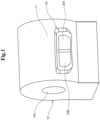
- the case 10 is a housing that houses the components of the handlebar switch device, and a cylindrical mounting hole 10A is formed therein as shown in Fig. 1 .
- the hole direction of the mounting hole 10A namely, a direction in which the inserted handlebar extends is the width direction of the vehicle. Therefore, in Fig. 1 , the substantially lateral direction is the width direction of the vehicle, which is the direction in which the handlebar extends, and the direction substantially perpendicular to the handlebar is the longitudinal direction of the vehicle.
- the near side shall be the driver's side, namely, the rear side of the vehicle.
- the handlebar switch device is not necessarily limited to being attached to the handlebar, and may be attached to a meter panel mounted on a scooter or the like or may be attached to any location of the vehicle that can be operated by the driver..
- the case 10 in this example embodiment has a surface located substantially parallel to a direction in which the handlebar extends, and has an arrangement surface 11 that is a surface facing the driver as shown in Fig. 1 , for example.
- the turn signal switch 20 operation unit for the driver to operate the turn signal 60 is provided on the arrangement surface 11 of the case 10.
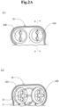
- the contact device 30 shown in Fig. 2A (2-1) is arranged on the inner surface side of the turn signal switch 20 described above.
- the contact device 30 has contact structural parts 30A and 30B corresponding to the turn signal operation surfaces 20A and 20B of the turn signal switch 20, respectively. Since the contact structural parts 30A and 30B have almost the same structure, the configuration of the contact structural part 30A corresponding to the right turn signal operation surface 20A will be described herein. Moreover, along with this, a case will be described in which the right turn signal 60 is actuated to light up among the turn signals 60 to be operated.
- Fig. 2A (2-2) is a view of the contact device 30 seen from the back side, and a lower end surface 33, which will be described later, is omitted from the drawing.
- Fig. 2B shows a cross-sectional part taken along line X-X of the contact structural part 30A shown in Fig. 2A (2-1).
- the surface of the contact structural part 30A shown in Fig. 2A (2-1) faces the inner surface that is the back surface of the turn signal operation surface 20A of the turn signal switch 20. Consequently, the surface of the contact structural part 30A (the upper surface in Fig. 2B ) is pressed and moved in a substantially perpendicular direction (first direction) to the turn signal operation surface 20A, that is, downward in Fig. 2B , along with an operation to press the turn signal operation surface 20A. Then, inside the contact structural part 30A, which is below the surface, as shown in the view seen from the back surface shown in Fig.
- the contact structural part 30A is configured to be energized, that is, turned on when the two types of contacts 31 and 32 having different height positions with respect to the lower end surface 33 come into contact with fixed contacts (not shown in the drawings) provided on the lower end surface 33 so as to correspond to the respective contacts 31 and 32.
- the contact height of the first contact 31 (first energizing means) with respect to the lower end surface 33 is set lower than the contact height of the second contact 32 (second energizing means). Consequently, when the contact structural part 30A is pressed downward in Fig. 2B along with the operation to press the turn signal operation surface 20A, the first contact 31 is brought into an energized state (first energized state) or the second contact 32 is brought into an energized state (second energized state) in accordance with the pressing force.
- a case where the second contact 32 is brought into the second energized state is a case where the first contact 31 is first brought into the first energized state and the surface of the contact structural part 30A is further pressed downward from the above state. Then, the energized states of the first contact 31 and the second contact 32 described above are detected by the control device 50.
- the contact structural part 30A is entirely made of an elastic member, and is configured to restore its shape when deformed by an external force. Consequently, in a case where the first contact 31 of the contact structure 30A is brought into the abovementioned energized state and thereafter the downward pressing operation on the contact structural part 30A is canceled, the contact structural part 30A restores its shape so as to separate from the lower end surface 33 and the first energized state is canceled. Likewise, in a case where the second contact 32 of the contact structural part 30A is brought into the abovementioned energized state and thereafter the downward pressing operation on the contact structural part 30A is canceled, the contact structural part 30A restores its shape so as to separate from the lower end surface 33 and the second energized state is canceled.
- the stop switch 40 is installed in a predetermined part of the case 10.
- the stop switch 40 is configured with, for example, a press-down switch and, when the driver operates to press down, the stop switch 40 is brought into an energized state (ON state) and outputs a stop signal to the control device 50.
- the stop signal output when the stop switch is operated is detected by the control device 50.
- the stop switch 40 is operated to be pressed down when the driver operates to stop the actuation of the turn signal 60.
- the control device 50 (control means) is configured with an arithmetic logic unit, and can realize processing to be described below by executing a program stored in an equipped memory unit. First, the control device 50 detects whether or not the first contact 31 and the second contact 32 of the contact structural part 30A described above are in the energized states. Then, the control device 50 controls the operation target turn signal 60 to be actuated to light up in accordance with the result of detection of the energized states of the first contact 31 and the second contact 32. Specifically, upon detecting the first energized state of the first contact 31, the control device 50 controls to actuate the right turn signal 60 to light up for a given time.
- the control device 50 controls to start the lighting of the turn signal 60, continue to actuate the turn signal to light up of until a predetermined period of time elapses after detection of the first energized state and, when the predetermined period of time elapses, automatically stop the lighting of the turn signal 60. At this time, even if the first energized state is canceled before the predetermined period of time elapses after the first energized state is detected, the control device 50 continues the lighting of the turn signal 60.
- the predetermined period of time to continue the lighting of the turn signal 60 may be any preset length of time, such as three seconds or a time for turning on the turn signal 60 three times.
- the control device 50 when detecting the second energized state of the second contact 32, the control device 50 continues the lighting of the turn signal 60 until detecting a stop signal output when the stop switch 40 is operated to be pressed down. Then, when the stop switch 40 is operated and the stop signal is detected, the control device 50 controls to stop the lighting of the turn signal 60.
- the control device 50 When detecting the second energized state of the second contact 32 as described above, the control device 50 has detected the first energized state of the first contact 31 beforehand and has already started the actuation of the turn signal 60 to light up. Consequently, when detecting the second energized state, the control device 50 continues the light-up of the turn signal 60 having already lit up until the stop switch 40 is operated and the stop signal is detected. At this time, even if the second energized state is canceled while the light-up of the turn signal 60 is continued after the second energized state is detected, the control device 50 continues the light-up of the turn signal 60.
- the driver performs an automatic stop operation to turn on the turn signal 60 and automatically stop in a predetermined period of time.
- the driver performs a press-down operation so as to push the turn signal operation surface 20A by the first distance, which is a short distance indicated by arrow Y1 in Fig. 3 (3-1), so that only the first contact 31 of the contact structural part 30A is energized. Consequently, the first contact 31 is brought into the first energized state and, when the control device 50 detects the energized state (Yes at step S1), the control device 50 controls to start the lighting of the turn signal 60 (step S2).
- the operation on the turn signal 60 is not limited to being performed by the pushing motion as described above, and may be performed by a swinging motion or a sliding motion. Accordingly, the contact device 30 may be configured such that the first contact 31 and the second contact 32 move as indicated by arrows in Fig. 3 when the turn signal operation surface 20A is swung or slid.
- the control device 50 After starting the lighting of the turn signal 60, the control device 50 keeps the lighting of the turn signal 60 until the predetermined time having been set elapses. At this time, even if the first energized state is canceled, the control device 50 continues the lighting of the turn signal 60. Then, in a case where a further pressing operation on the turn signal switch 20 by the driver is not performed and the second energized state of the second contact 32 is not detected (No at step S3) and the predetermined period of time elapses (Yes at step S4), the control device 50 controls to stop the lighting of the turn signal 60 (step S6).
- the driver's operation on the turn signal switch 20 so that only the first contact 31 is brough into the energized state, it is possible to keep the turn signal 60 turned on for a predetermined period of time by the driver's will and automatically stop.
- the driver performs a usual turn signal operation, that is, an operation to turn on the turn signal 60 and thereafter operates the stop switch 40 to perform an operation to stop the lighting.
- the driver performs a press-down operation to push the turn signal operation surface 20A by the second distance, which is a long distance indicated by arrow Y2 in Fig. 3 (3-2). Consequently, first, the first contact 31 is brought into the first energized state and, when the control device 50 detects the energized state (Yes at step S1), the control device 50 starts the lighting of the turn signal 60 (step S2).
- the second contact 32 is brought into the second energized state and, when the control device 50 detects the energized state (Yes at step S3), the control device 50 continues the lighting of the turn signal 60 until a stop operation is performed on the turn signal 60 (No at step S5). At this time, the control device 50 continues the lighting of the turn signal 60 even when the second energized state and the first energized state are canceled. In this case, the lighting of the turn signal 60 is not stopped even if the predetermined period of time elapses.
- the driver performs a press-down operation on the stop switch 40 and the stop switch 40 is brought into an energized state and, when the control device 50 detects a stop signal thus output (Yes at step S5), the control device 50 stops the lighting of the turn signal 60 (step S6).
- the driver can operate the turn signal switch 20 until the second contact 32 is brought into the energized state as described above and thereby continue the lighting of the turn signal 60 until operating the stop switch 40.
- the stop signal is not limited to being output by the operation on the stop switch 40 as described above.
- the stop signal may be output to the control device 50 described above from another control device mounted on the vehicle in accordance with the condition of the vehicle such as vehicle speed and mileage.
- a switch for operating another device may be provided instead of the turn signal switch 20, and accordingly, the control device 50 may control the actuation of the other device.
- a device to be the target for control of actuation may be a headlamp, and the control device may control to light the headlamp for a predetermined period of time in the abovementioned first energized state and control to continue the lighting of the headlamp in the second energized state.
- control means continues the actuation of the device until the predetermined period of time elapses after the detection of the first energized state and stops the actuation of the device when the predetermined period of time elapses, and continues the actuation of the device until detection of a preset stop signal upon detection of the second energized state and stops the actuation of the device upon detection of the stop signal.
- a control method by a handlebar switch device comprising:
- the control method according to Claim 8 comprising continuing the actuation of the device until the predetermined period of time elapses after the detection of the first energized state and stopping the actuation of the device when the predetermined period of time elapses, and continuing the actuation of the device until detection of a preset stop signal upon detection of the second energized state and stopping the actuation of the device upon detecting the stop signal.
Landscapes
- Engineering & Computer Science (AREA)
- Mechanical Engineering (AREA)
- Lighting Device Outwards From Vehicle And Optical Signal (AREA)
Abstract
Description
- This application is based upon and claims the benefit of priority from
Japanese patent application No. 2023-085113, filed on May 24, 2023 - The present invention relates to a handlebar switch device.
- A handlebar switch device installed on a vehicle such as a motorcycle is equipped with various operation switches. For example, a handlebar switch device is equipped with a turn signal switch that controls the actuation of left and right turn signals, and Patent Literature 1 describes controlling the actuation of a turn signal. Specifically, Patent Literature 1 describes that the turn signal is automatically stopped in accordance with the driving condition of the vehicle after the actuation of the turn signal.
- Patent Literature 1:
Japanese Patent Publication No. 6077883 - However, in the case of the technique described in Patent Literature 1, there is a risk that the turn signal is automatically stopped at a timing unintended by the operator in accordance with the driving condition of the vehicle. Consequently, a problem occurs that it is not possible to perform an automatic stop operation in accordance with the operator's will. Such a problem may also occur in not only a turn signal switch but also another switch that controls the actuation of another device.
- An object of the present invention is to provide a handlebar switch device that can solve the abovementioned problem, namely, a problem that it is not possible to perform an automatic stop control of the actuation of a device by the operator's will.
- A handlebar switch device as an aspect of the present invention includes: a first energizing means that enters a first energized state when an operation unit is operated in a first direction; a second energizing means that enters a second energized state when the operation unit is further operated in the first direction during the first energized state; and a control means that actuates a device corresponding to the operation unit in accordance with the first energized state and the second energized state detected thereby. The control means actuates the device upon detection of the first energized state, and stops the actuation of the device when a predetermined period of time elapses after the detection of the first energized state.
- Further, a control method as an aspect of the present invention is a control method by a handlebar switch device that includes: a first energizing means that enters a first energized state when an operation unit is operated in a first direction; a second energizing means that enters a second energized state when the operation unit is further operated in the first direction during the first energized state; and a control means that actuates a device corresponding to the operation unit in accordance with the first energized state and the second energized state detected thereby. The control method includes actuating the device upon detection of the first energized state, and stopping the actuation of the device when a predetermined period of time elapses after the detection of the first energized state.
- With the configurations as described above, the present invention enables an automatic stop control of the actuation of a device by the operator's will in a handlebar switch device.
-
-
Fig. 1 is a view showing the configuration of a handlebar switch device in a first example embodiment of the present invention; -
Fig. 2A is a view showing the configuration of a contact device of a turn signal switch disclosed inFig. 1 ; -
Fig. 2B is a view showing the configuration of the contact device of the turn signal switch disclosed inFig. 1 ; -
Fig. 3 is a view showing the configuration of the contact device of the turn signal switch disclosed inFig. 1 ; -
Fig. 4 is a view showing the configuration of an operation system including the turn signal switch disclosed inFig. 1 ; and -
Fig. 5 is a flowchart showing the motion of a turn signal by an operation on the turn signal switch disclosed inFig. 1 . - A first example embodiment of the present invention will be described with reference to
Figs. 1 to 5 .Figs. 1 to 4 are views for describing the configuration of a handlebar switch device, andFig. 5 is a view for describing the motion of a turn signal by an operation on the handlebar switch device. - The handlebar switch device in the present invention is installed, for example, on the handlebar of a straddle-type vehicle such as a motorcycle, and is equipped with various operation switches. In this example embodiment, a case will be illustrated in which a turn signal switch for operating left and right turn signals to light up is mounted as the operation switch mounted on the handlebar switch device. However, the operation switch mounted on the handlebar switch device is not limited to the turn signal switch, and may be any operation switch for operating another device. Meanwhile, the straddle-type vehicle on which the handlebar switch device is mounted is not limited to a motorcycle, and may be any vehicle.
- As shown in
Fig. 1 , the handlebar switch device in this example embodiment includes acase 10 that forms the outer shape of the handlebar switch device, aturn signal switch 20 provided on a predetermined surface of thecase 10, and acontact device 30 located on the inner surface side of theturn signal switch 20 and mounted inside thecase 10. Then, in this example embodiment, as an operation system by the handlebar switch device, astop switch 40 mounted in a predetermined position of thecase 10, acontrol device 50 that detects the operation statuses of thecontact device 30 of theturn signal switch 20 and thestop switch 40 and controls the actuation of aturn signal 60, and theturn signal 60 to be operated with theturn signal switch 20 and thestop switch 40 are included as shown inFig. 4 . - The
case 10 is a housing that houses the components of the handlebar switch device, and acylindrical mounting hole 10A is formed therein as shown inFig. 1 . By inserting a handlebar for steering the vehicle that is a motorcycle into themounting hole 10A, thecase 10 can be placed on the handlebar. In this example embodiment, the hole direction of themounting hole 10A, namely, a direction in which the inserted handlebar extends is the width direction of the vehicle. Therefore, inFig. 1 , the substantially lateral direction is the width direction of the vehicle, which is the direction in which the handlebar extends, and the direction substantially perpendicular to the handlebar is the longitudinal direction of the vehicle. InFig. 1 , the near side shall be the driver's side, namely, the rear side of the vehicle. Meanwhile, the handlebar switch device is not necessarily limited to being attached to the handlebar, and may be attached to a meter panel mounted on a scooter or the like or may be attached to any location of the vehicle that can be operated by the driver.. - The
case 10 in this example embodiment has a surface located substantially parallel to a direction in which the handlebar extends, and has anarrangement surface 11 that is a surface facing the driver as shown inFig. 1 , for example. Then, as shown inFig. 1 , the turn signal switch 20 (operation unit) for the driver to operate theturn signal 60 is provided on thearrangement surface 11 of thecase 10. On the surface of theturn signal switch 20, there are formed a right turnsignal operation surface 20A and a left turnsignal operation surface 20B, which are located side by side in the width direction of thecase 10, that is, in the horizontal direction as seen from the driver. By pressing the turnsignal operation surface left turn signal 60 to light up as described below. - The
contact device 30 shown inFig. 2A (2-1) is arranged on the inner surface side of theturn signal switch 20 described above. Thecontact device 30 has contactstructural parts signal operation surfaces turn signal switch 20, respectively. Since the contactstructural parts structural part 30A corresponding to the right turnsignal operation surface 20A will be described herein. Moreover, along with this, a case will be described in which theright turn signal 60 is actuated to light up among theturn signals 60 to be operated.Fig. 2A (2-2) is a view of thecontact device 30 seen from the back side, and alower end surface 33, which will be described later, is omitted from the drawing. -
Fig. 2B shows a cross-sectional part taken along line X-X of the contactstructural part 30A shown inFig. 2A (2-1). The surface of the contactstructural part 30A shown inFig. 2A (2-1) faces the inner surface that is the back surface of the turnsignal operation surface 20A of theturn signal switch 20. Consequently, the surface of the contactstructural part 30A (the upper surface inFig. 2B ) is pressed and moved in a substantially perpendicular direction (first direction) to the turnsignal operation surface 20A, that is, downward inFig. 2B , along with an operation to press the turnsignal operation surface 20A. Then, inside the contactstructural part 30A, which is below the surface, as shown in the view seen from the back surface shown inFig. 2A (2-2) and the cross-sectional view inFig. 2B , two types ofcontacts structural part 30A is configured to be energized, that is, turned on when the two types ofcontacts lower end surface 33 come into contact with fixed contacts (not shown in the drawings) provided on thelower end surface 33 so as to correspond to therespective contacts lower end surface 33 is set lower than the contact height of the second contact 32 (second energizing means). Consequently, when the contactstructural part 30A is pressed downward inFig. 2B along with the operation to press the turnsignal operation surface 20A, thefirst contact 31 is brought into an energized state (first energized state) or thesecond contact 32 is brought into an energized state (second energized state) in accordance with the pressing force. - For example, as indicated by arrow Y1 in
Fig. 3 (3-1), when the surface of the contactstructural part 30A is pressed downward by a first distance, which is the distance between thefirst contact 31 and thelower end surface 33, thefirst contact 31 is energized, that is, brought into the first energized state. Moreover, as indicated by arrow Y2 inFig. 3 (3-2), when the surface of the contactstructural part 30A is pressed downward by the second distance, which is longer than the abovementioned first distance and is the distance between thesecond contact 32 and thelower end surface 33, thesecond contact 32 is energized, that is, brought into the second energized state. A case where thesecond contact 32 is brought into the second energized state is a case where thefirst contact 31 is first brought into the first energized state and the surface of the contactstructural part 30A is further pressed downward from the above state. Then, the energized states of thefirst contact 31 and thesecond contact 32 described above are detected by thecontrol device 50. - The contact
structural part 30A is entirely made of an elastic member, and is configured to restore its shape when deformed by an external force. Consequently, in a case where thefirst contact 31 of thecontact structure 30A is brought into the abovementioned energized state and thereafter the downward pressing operation on the contactstructural part 30A is canceled, the contactstructural part 30A restores its shape so as to separate from thelower end surface 33 and the first energized state is canceled. Likewise, in a case where thesecond contact 32 of the contactstructural part 30A is brought into the abovementioned energized state and thereafter the downward pressing operation on the contactstructural part 30A is canceled, the contactstructural part 30A restores its shape so as to separate from thelower end surface 33 and the second energized state is canceled. - The
stop switch 40 is installed in a predetermined part of thecase 10. Thestop switch 40 is configured with, for example, a press-down switch and, when the driver operates to press down, thestop switch 40 is brought into an energized state (ON state) and outputs a stop signal to thecontrol device 50. The stop signal output when the stop switch is operated is detected by thecontrol device 50. Thestop switch 40 is operated to be pressed down when the driver operates to stop the actuation of theturn signal 60. - The control device 50 (control means) is configured with an arithmetic logic unit, and can realize processing to be described below by executing a program stored in an equipped memory unit. First, the
control device 50 detects whether or not thefirst contact 31 and thesecond contact 32 of the contactstructural part 30A described above are in the energized states. Then, thecontrol device 50 controls the operationtarget turn signal 60 to be actuated to light up in accordance with the result of detection of the energized states of thefirst contact 31 and thesecond contact 32. Specifically, upon detecting the first energized state of thefirst contact 31, thecontrol device 50 controls to actuate theright turn signal 60 to light up for a given time. That is to say, upon detecting the first energized state, thecontrol device 50 controls to start the lighting of theturn signal 60, continue to actuate the turn signal to light up of until a predetermined period of time elapses after detection of the first energized state and, when the predetermined period of time elapses, automatically stop the lighting of theturn signal 60. At this time, even if the first energized state is canceled before the predetermined period of time elapses after the first energized state is detected, thecontrol device 50 continues the lighting of theturn signal 60. The predetermined period of time to continue the lighting of theturn signal 60 may be any preset length of time, such as three seconds or a time for turning on theturn signal 60 three times. - Further, when detecting the second energized state of the
second contact 32, thecontrol device 50 continues the lighting of theturn signal 60 until detecting a stop signal output when thestop switch 40 is operated to be pressed down. Then, when thestop switch 40 is operated and the stop signal is detected, thecontrol device 50 controls to stop the lighting of theturn signal 60. When detecting the second energized state of thesecond contact 32 as described above, thecontrol device 50 has detected the first energized state of thefirst contact 31 beforehand and has already started the actuation of theturn signal 60 to light up. Consequently, when detecting the second energized state, thecontrol device 50 continues the light-up of theturn signal 60 having already lit up until thestop switch 40 is operated and the stop signal is detected. At this time, even if the second energized state is canceled while the light-up of theturn signal 60 is continued after the second energized state is detected, thecontrol device 50 continues the light-up of theturn signal 60. - Next, the motion when the
abovementioned turn signal 20 is operated will be described mainly with reference to a flowchart ofFig. 5 . Here, a case will be described in which, of the turn signal switches 20, the turnsignal operation surface 20A on the right side shown inFig. 1 is operated, that is, theright turn signal 60 is operated by the driver. - First, a case will be described in which, for example, when making the vehicle change lanes, the driver performs an automatic stop operation to turn on the
turn signal 60 and automatically stop in a predetermined period of time. In this case, the driver performs a press-down operation so as to push the turnsignal operation surface 20A by the first distance, which is a short distance indicated by arrow Y1 inFig. 3 (3-1), so that only thefirst contact 31 of the contactstructural part 30A is energized. Consequently, thefirst contact 31 is brought into the first energized state and, when thecontrol device 50 detects the energized state (Yes at step S1), thecontrol device 50 controls to start the lighting of the turn signal 60 (step S2). The operation on theturn signal 60 is not limited to being performed by the pushing motion as described above, and may be performed by a swinging motion or a sliding motion. Accordingly, thecontact device 30 may be configured such that thefirst contact 31 and thesecond contact 32 move as indicated by arrows inFig. 3 when the turnsignal operation surface 20A is swung or slid. - After starting the lighting of the
turn signal 60, thecontrol device 50 keeps the lighting of theturn signal 60 until the predetermined time having been set elapses. At this time, even if the first energized state is canceled, thecontrol device 50 continues the lighting of theturn signal 60. Then, in a case where a further pressing operation on theturn signal switch 20 by the driver is not performed and the second energized state of thesecond contact 32 is not detected (No at step S3) and the predetermined period of time elapses (Yes at step S4), thecontrol device 50 controls to stop the lighting of the turn signal 60 (step S6). Thus, by the driver's operation on theturn signal switch 20 so that only thefirst contact 31 is brough into the energized state, it is possible to keep theturn signal 60 turned on for a predetermined period of time by the driver's will and automatically stop. - Next, a case will be described in which the driver performs a usual turn signal operation, that is, an operation to turn on the
turn signal 60 and thereafter operates thestop switch 40 to perform an operation to stop the lighting. In this case, the driver performs a press-down operation to push the turnsignal operation surface 20A by the second distance, which is a long distance indicated by arrow Y2 inFig. 3 (3-2). Consequently, first, thefirst contact 31 is brought into the first energized state and, when thecontrol device 50 detects the energized state (Yes at step S1), thecontrol device 50 starts the lighting of the turn signal 60 (step S2). Furthermore, since the press-down operation is performed on the turnsignal operation surface 20A, thesecond contact 32 is brought into the second energized state and, when thecontrol device 50 detects the energized state (Yes at step S3), thecontrol device 50 continues the lighting of theturn signal 60 until a stop operation is performed on the turn signal 60 (No at step S5). At this time, thecontrol device 50 continues the lighting of theturn signal 60 even when the second energized state and the first energized state are canceled. In this case, the lighting of theturn signal 60 is not stopped even if the predetermined period of time elapses. - After that, the driver performs a press-down operation on the
stop switch 40 and thestop switch 40 is brought into an energized state and, when thecontrol device 50 detects a stop signal thus output (Yes at step S5), thecontrol device 50 stops the lighting of the turn signal 60 (step S6). Thus, in a case where there is no need to automatically stop the lighting of theturn signal 60 as described above, the driver can operate theturn signal switch 20 until thesecond contact 32 is brought into the energized state as described above and thereby continue the lighting of theturn signal 60 until operating thestop switch 40. Meanwhile, the stop signal is not limited to being output by the operation on thestop switch 40 as described above. For example, the stop signal may be output to thecontrol device 50 described above from another control device mounted on the vehicle in accordance with the condition of the vehicle such as vehicle speed and mileage. - Although a case in which the
turn signal switch 20 is mounted on the handlebar switch device and theturn signal 60 is actuated to light up has been illustrated above, a switch for operating another device may be provided instead of theturn signal switch 20, and accordingly, thecontrol device 50 may control the actuation of the other device. For example, a device to be the target for control of actuation may be a headlamp, and the control device may control to light the headlamp for a predetermined period of time in the abovementioned first energized state and control to continue the lighting of the headlamp in the second energized state. - The whole or part of the example embodiments disclosed above can be described as the following supplementary notes. Below, the overview of a handlebar switch device in the present invention will be described. However, the present invention is not limited to the following configurations.
-
- 1. A handlebar switch device comprising:
- a first energizing means that enters a first energized state when an operation unit is operated in a first direction;
- a second energizing means that enters a second energized state when the operation unit is further operated in the first direction during the first energized state; and
- a control means that actuates a device corresponding to the operation unit in accordance with the first energized state and the second energized state detected thereby,
- wherein the control means actuates the device upon detection of the first energized state, and stops the actuation of the device when a predetermined period of time elapses after the detection of the first energized state.
- The handlebar switch device according to Supplementary Note 1, wherein
the control means continues the actuation of the device until the predetermined period of time elapses after the detection of the first energized state and stops the actuation of the device when the predetermined period of time elapses, and continues the actuation of the device until detection of a preset stop signal upon detection of the second energized state and stops the actuation of the device upon detection of the stop signal. - The handlebar switch device according to Supplementary Note 2, wherein:
- the first energizing means cancels the first energized state when the operation on the operation unit in the first direction is canceled;
- the second energizing means cancels the second energizing state when the operation on the operation unit in the first direction is canceled; and
- the control means continues the actuation of the device until the predetermined period of time elapses after the detection of the first energized state even in a case where the first energized state is canceled, and continues the actuation of the device until detection of the stop signal after the detection of the second energized state even in a case where the second energized state is canceled.
- The handlebar switch device according to Supplementary Note 3, wherein:
- the first energizing means is configured to enter the first energized state when the operation unit is pressed by a first distance in the first direction, and cancel the first energized state when the press is canceled; and
- the second energizing means is configured to enter the second energized state when the operation unit is pressed by a second distance that is longer than the first distance in the first direction, and cancel the second energized state when the press is canceled.
- The handlebar switch device according to any of Supplementary Notes 2 to 4, wherein:
- the device is controlled by the control means to be actuated to light up; and
- the control means continues the light-up actuation of the device until the predetermined period of time elapses after the detection of the first energized state, and continues the light-up actuation of the device until detection of the stop signal after the detection of the second energized state.
- The handlebar switch device according to Supplementary Note 5, wherein:
- the device is a turn signal; and
- the control means continues the actuation of the turn signal until the predetermined period of time elapses after the detection of the first energized state, and continues the actuation of the turn signal until detection of the stop signal after the detection of the second energized state.
- The handlebar switch device according to any of Supplementary Notes 2 to 6, wherein
the control means detects the second energized state and continues the actuation of the device, and stops the actuation of the device when detecting the stop signal output from a control device mounted on a vehicle equipped with the device. - A control method by a handlebar switch device, the handlebar switch device comprising:
- a first energizing means that enters a first energized state when an operation unit is operated in a first direction;
- a second energizing means that enters a second energized state when the operation unit is further operated in the first direction during the first energized state; and
- a control means that actuates a device corresponding to the operation unit in accordance with the first energized state and the second energized state detected thereby,
- the control method comprising
- actuating the device upon detection of the first energized state, and stopping the actuation of the device when a predetermined period of time elapses after the detection of the first energized state.
- The control method according to Claim 8, comprising
continuing the actuation of the device until the predetermined period of time elapses after the detection of the first energized state and stopping the actuation of the device when the predetermined period of time elapses, and continuing the actuation of the device until detection of a preset stop signal upon detection of the second energized state and stopping the actuation of the device upon detecting the stop signal. - Although the present invention has been described above with reference to the example embodiments, the present invention is not limited to the above example embodiments. The configurations and details of the present invention can be changed in various manners that can be understood by on skilled in the part.
-
- 10
- case
- 10A
- mounting hole
- 11
- arrangement surface
- 20
- turn signal switch
- 20A, 20B
- turn signal operation surface
- 30
- contact device
- 30A, 30B
- contact structural part
- 31
- first contact
- 32
- second contact
- 33
- lower end surface
- 40
- stop switch
- 50
- control device
- 60
- turn signal
Claims (9)
- A handlebar switch device comprising:a first energizing means that enters a first energized state when an operation unit is operated in a first direction;a second energizing means that enters a second energized state when the operation unit is further operated in the first direction during the first energized state; anda control means that actuates a device corresponding to the operation unit in accordance with the first energized state and the second energized state detected thereby,wherein the control means actuates the device upon detection of the first energized state, and stops the actuation of the device when a predetermined period of time elapses after the detection of the first energized state.
- The handlebar switch device according to Claim 1, wherein
the control means continues the actuation of the device until the predetermined period of time elapses after the detection of the first energized state and stops the actuation of the device when the predetermined period of time elapses, and continues the actuation of the device until detection of a preset stop signal upon detection of the second energized state and stops the actuation of the device upon detection of the stop signal. - The handlebar switch device according to Claim 2, wherein:the first energizing means cancels the first energized state when the operation on the operation unit in the first direction is canceled;the second energizing means cancels the second energizing state when the operation on the operation unit in the first direction is canceled; andthe control means continues the actuation of the device until the predetermined period of time elapses after the detection of the first energized state even in a case where the first energized state is canceled, and continues the actuation of the device until detection of the stop signal after the detection of the second energized state even in a case where the second energized state is canceled.
- The handlebar switch device according to any one of Claims 1 to 3, wherein:the first energizing means is configured to enter the first energized state when the operation unit is pressed by a first distance in the first direction, and cancel the first energized state when the press is canceled; andthe second energizing means is configured to enter the second energized state when the operation unit is pressed by a second distance that is longer than the first distance in the first direction, and cancel the second energized state when the press is canceled.
- The handlebar switch device according to Claim 2, wherein:the device is controlled by the control means to be actuated to light up; andthe control means continues the light-up actuation of the device until the predetermined period of time elapses after the detection of the first energized state, and continues the light-up actuation of the device until detection of the stop signal after the detection of the second energized state.
- The handlebar switch device according to Claim 5, wherein:the device is a turn signal; andthe control means continues the actuation of the turn signal until the predetermined period of time elapses after the detection of the first energized state, and continues the actuation of the turn signal until detection of the stop signal after the detection of the second energized state.
- The handlebar switch device according to Claim 2, wherein
the control means detects the second energized state and continues the actuation of the device, and stops the actuation of the device when detecting the stop signal output from a control device mounted on a vehicle equipped with the device. - A control method by a handlebar switch device, the handlebar switch device comprising:a first energizing means that enters a first energized state when an operation unit is operated in a first direction;a second energizing means that enters a second energized state when the operation unit is further operated in the first direction during the first energized state; anda control means that actuates a device corresponding to the operation unit in accordance with the first energized state and the second energized state detected thereby,the control method comprisingactuating the device upon detection of the first energized state, and stopping the actuation of the device when a predetermined period of time elapses after the detection of the first energized state.
- The control method according to Claim 8, comprising
continuing the actuation of the device until the predetermined period of time elapses after the detection of the first energized state and stopping the actuation of the device when the predetermined period of time elapses, and continuing the actuation of the device until detection of a preset stop signal upon detection of the second energized state and stopping the actuation of the device upon detecting the stop signal.
Applications Claiming Priority (1)
| Application Number | Priority Date | Filing Date | Title |
|---|---|---|---|
| JP2023085113A JP2024168426A (en) | 2023-05-24 | 2023-05-24 | Handle switch device |
Publications (1)
| Publication Number | Publication Date |
|---|---|
| EP4467434A1 true EP4467434A1 (en) | 2024-11-27 |
Family
ID=90720521
Family Applications (1)
| Application Number | Title | Priority Date | Filing Date |
|---|---|---|---|
| EP24169388.6A Pending EP4467434A1 (en) | 2023-05-24 | 2024-04-10 | Handlebar switch device |
Country Status (3)
| Country | Link |
|---|---|
| EP (1) | EP4467434A1 (en) |
| JP (1) | JP2024168426A (en) |
| CN (1) | CN119018270A (en) |
Citations (5)
| Publication number | Priority date | Publication date | Assignee | Title |
|---|---|---|---|---|
| US8723659B2 (en) * | 2012-07-10 | 2014-05-13 | Shimano Inc. | Bicycle gear shift indicator |
| EP3093228A1 (en) * | 2009-03-31 | 2016-11-16 | Shimano Inc. | Bicycle shifting control apparatus |
| JP6077883B2 (en) | 2013-02-27 | 2017-02-08 | 本田技研工業株式会社 | Blinker cancellation device for vehicle |
| JP6417835B2 (en) * | 2014-10-03 | 2018-11-07 | スズキ株式会社 | Handle switch system |
| JP2023085113A (en) | 2021-12-08 | 2023-06-20 | 株式会社キトー | Electric hoisting machine and control method of electric hoisting machine |
-
2023
- 2023-05-24 JP JP2023085113A patent/JP2024168426A/en active Pending
-
2024
- 2024-04-10 EP EP24169388.6A patent/EP4467434A1/en active Pending
- 2024-05-17 CN CN202410616314.8A patent/CN119018270A/en active Pending
Patent Citations (5)
| Publication number | Priority date | Publication date | Assignee | Title |
|---|---|---|---|---|
| EP3093228A1 (en) * | 2009-03-31 | 2016-11-16 | Shimano Inc. | Bicycle shifting control apparatus |
| US8723659B2 (en) * | 2012-07-10 | 2014-05-13 | Shimano Inc. | Bicycle gear shift indicator |
| JP6077883B2 (en) | 2013-02-27 | 2017-02-08 | 本田技研工業株式会社 | Blinker cancellation device for vehicle |
| JP6417835B2 (en) * | 2014-10-03 | 2018-11-07 | スズキ株式会社 | Handle switch system |
| JP2023085113A (en) | 2021-12-08 | 2023-06-20 | 株式会社キトー | Electric hoisting machine and control method of electric hoisting machine |
Also Published As
| Publication number | Publication date |
|---|---|
| CN119018270A (en) | 2024-11-26 |
| JP2024168426A (en) | 2024-12-05 |
Similar Documents
| Publication | Publication Date | Title |
|---|---|---|
| US7755294B2 (en) | Vehicle headlight beam controls | |
| EP2660091B1 (en) | Shifting apparatus for automatic transmission | |
| EP4001072B1 (en) | Straddle vehicle and light control method thereof | |
| US10843621B2 (en) | Lever switch and automatic light control device | |
| JP5121000B2 (en) | Steering column lock device with push release function | |
| JP2010143542A (en) | Electric parking brake system | |
| JP7060637B2 (en) | Vehicle light system | |
| JP6229434B2 (en) | Vehicle control device | |
| JP2008179209A (en) | Vehicle travel system combination switch device | |
| JP2010006192A (en) | Shift operation device | |
| JP5244948B2 (en) | Shift device | |
| JP2008181718A (en) | Impact-absorbing structure of vehicle driver's seat | |
| KR20100121902A (en) | Electronic parking brake system and release method thereof | |
| JP5471458B2 (en) | Vehicle travel control device | |
| JP2024168426A (en) | Handle switch device | |
| JP7554545B2 (en) | Shifting device | |
| JP2022087268A (en) | Light system for vehicle | |
| JPH05246266A (en) | Speed change control for automatic transmission | |
| JP2007246033A (en) | Power control device | |
| CN112644474B (en) | Parking assist device | |
| KR101417384B1 (en) | Apparatus and method for guiding of multi-function switch | |
| KR102104810B1 (en) | Device for control the start and method thereof | |
| CN115892199B (en) | vehicle | |
| JP4814036B2 (en) | Operation pedal support structure | |
| EP0390210A1 (en) | Safety shift-lock device for selector of automatic power transmission |
Legal Events
| Date | Code | Title | Description |
|---|---|---|---|
| PUAI | Public reference made under article 153(3) epc to a published international application that has entered the european phase |
Free format text: ORIGINAL CODE: 0009012 |
|
| STAA | Information on the status of an ep patent application or granted ep patent |
Free format text: STATUS: THE APPLICATION HAS BEEN PUBLISHED |
|
| AK | Designated contracting states |
Kind code of ref document: A1 Designated state(s): AL AT BE BG CH CY CZ DE DK EE ES FI FR GB GR HR HU IE IS IT LI LT LU LV MC ME MK MT NL NO PL PT RO RS SE SI SK SM TR |
|
| STAA | Information on the status of an ep patent application or granted ep patent |
Free format text: STATUS: REQUEST FOR EXAMINATION WAS MADE |
|
| 17P | Request for examination filed |
Effective date: 20250203 |
|
| REG | Reference to a national code |
Ref country code: DE Ref legal event code: R079 Free format text: PREVIOUS MAIN CLASS: B62K0021120000 Ipc: B62K0023020000 |
|
| RIC1 | Information provided on ipc code assigned before grant |
Ipc: B62K 23/02 20060101AFI20260331BHEP Ipc: B62J 6/056 20200101ALN20260331BHEP Ipc: B62J 6/16 20200101ALN20260331BHEP |
|
| GRAP | Despatch of communication of intention to grant a patent |
Free format text: ORIGINAL CODE: EPIDOSNIGR1 |
|
| STAA | Information on the status of an ep patent application or granted ep patent |
Free format text: STATUS: GRANT OF PATENT IS INTENDED |