EP4467399A1 - In-sensor crash detection with motion sensors - Google Patents
In-sensor crash detection with motion sensors Download PDFInfo
- Publication number
- EP4467399A1 EP4467399A1 EP24172992.0A EP24172992A EP4467399A1 EP 4467399 A1 EP4467399 A1 EP 4467399A1 EP 24172992 A EP24172992 A EP 24172992A EP 4467399 A1 EP4467399 A1 EP 4467399A1
- Authority
- EP
- European Patent Office
- Prior art keywords
- sensor
- sensor data
- class
- output
- processor
- Prior art date
- Legal status (The legal status is an assumption and is not a legal conclusion. Google has not performed a legal analysis and makes no representation as to the accuracy of the status listed.)
- Pending
Links
Images


Classifications
-
- B—PERFORMING OPERATIONS; TRANSPORTING
- B60—VEHICLES IN GENERAL
- B60R—VEHICLES, VEHICLE FITTINGS, OR VEHICLE PARTS, NOT OTHERWISE PROVIDED FOR
- B60R21/00—Arrangements or fittings on vehicles for protecting or preventing injuries to occupants or pedestrians in case of accidents or other traffic risks
- B60R21/01—Electrical circuits for triggering passive safety arrangements, e.g. airbags, safety belt tighteners, in case of vehicle accidents or impending vehicle accidents
- B60R21/013—Electrical circuits for triggering passive safety arrangements, e.g. airbags, safety belt tighteners, in case of vehicle accidents or impending vehicle accidents including means for detecting collisions, impending collisions or roll-over
- B60R21/0132—Electrical circuits for triggering passive safety arrangements, e.g. airbags, safety belt tighteners, in case of vehicle accidents or impending vehicle accidents including means for detecting collisions, impending collisions or roll-over responsive to vehicle motion parameters, e.g. to vehicle longitudinal or transversal deceleration or speed value
-
- B—PERFORMING OPERATIONS; TRANSPORTING
- B60—VEHICLES IN GENERAL
- B60R—VEHICLES, VEHICLE FITTINGS, OR VEHICLE PARTS, NOT OTHERWISE PROVIDED FOR
- B60R21/00—Arrangements or fittings on vehicles for protecting or preventing injuries to occupants or pedestrians in case of accidents or other traffic risks
- B60R21/01—Electrical circuits for triggering passive safety arrangements, e.g. airbags, safety belt tighteners, in case of vehicle accidents or impending vehicle accidents
-
- B—PERFORMING OPERATIONS; TRANSPORTING
- B60—VEHICLES IN GENERAL
- B60R—VEHICLES, VEHICLE FITTINGS, OR VEHICLE PARTS, NOT OTHERWISE PROVIDED FOR
- B60R21/00—Arrangements or fittings on vehicles for protecting or preventing injuries to occupants or pedestrians in case of accidents or other traffic risks
-
- B—PERFORMING OPERATIONS; TRANSPORTING
- B60—VEHICLES IN GENERAL
- B60R—VEHICLES, VEHICLE FITTINGS, OR VEHICLE PARTS, NOT OTHERWISE PROVIDED FOR
- B60R21/00—Arrangements or fittings on vehicles for protecting or preventing injuries to occupants or pedestrians in case of accidents or other traffic risks
- B60R21/01—Electrical circuits for triggering passive safety arrangements, e.g. airbags, safety belt tighteners, in case of vehicle accidents or impending vehicle accidents
- B60R21/013—Electrical circuits for triggering passive safety arrangements, e.g. airbags, safety belt tighteners, in case of vehicle accidents or impending vehicle accidents including means for detecting collisions, impending collisions or roll-over
- B60R21/0136—Electrical circuits for triggering passive safety arrangements, e.g. airbags, safety belt tighteners, in case of vehicle accidents or impending vehicle accidents including means for detecting collisions, impending collisions or roll-over responsive to actual contact with an obstacle, e.g. to vehicle deformation, bumper displacement or bumper velocity relative to the vehicle
-
- B—PERFORMING OPERATIONS; TRANSPORTING
- B60—VEHICLES IN GENERAL
- B60R—VEHICLES, VEHICLE FITTINGS, OR VEHICLE PARTS, NOT OTHERWISE PROVIDED FOR
- B60R21/00—Arrangements or fittings on vehicles for protecting or preventing injuries to occupants or pedestrians in case of accidents or other traffic risks
- B60R2021/0027—Post collision measures, e.g. notifying emergency services
-
- B—PERFORMING OPERATIONS; TRANSPORTING
- B60—VEHICLES IN GENERAL
- B60R—VEHICLES, VEHICLE FITTINGS, OR VEHICLE PARTS, NOT OTHERWISE PROVIDED FOR
- B60R21/00—Arrangements or fittings on vehicles for protecting or preventing injuries to occupants or pedestrians in case of accidents or other traffic risks
- B60R21/01—Electrical circuits for triggering passive safety arrangements, e.g. airbags, safety belt tighteners, in case of vehicle accidents or impending vehicle accidents
- B60R2021/01013—Means for detecting collision, impending collision or roll-over
- B60R2021/01027—Safing sensors
-
- B—PERFORMING OPERATIONS; TRANSPORTING
- B60—VEHICLES IN GENERAL
- B60R—VEHICLES, VEHICLE FITTINGS, OR VEHICLE PARTS, NOT OTHERWISE PROVIDED FOR
- B60R21/00—Arrangements or fittings on vehicles for protecting or preventing injuries to occupants or pedestrians in case of accidents or other traffic risks
- B60R21/01—Electrical circuits for triggering passive safety arrangements, e.g. airbags, safety belt tighteners, in case of vehicle accidents or impending vehicle accidents
- B60R2021/0104—Communication circuits for data transmission
- B60R2021/01081—Transmission medium
- B60R2021/01088—Transmission medium wireless
Definitions
- the present invention relates generally to crash detection systems, and more particularly to crash detection systems that can detect a crash without receiving input from external devices.
- a Car Crash Detection (CCD) feature is used to automatically help a user in the event that the user is involved in a car accident.
- CCD Car Crash Detection
- a CCD feature typically calls for medical help if a car accident is detected.
- Existing car crash detection systems use a so-called "high-g” accelerometer in order to measure peak acceleration that results from an accident, which could reach more than 100 g ( i.e., one hundred times the force of gravity).
- existing car crash detection systems included in smartphone devices use information that comes from multiple external devices, including a Global Positioning System (GPS) receiver, a plurality of motion sensors, and a microphone.
- GPS Global Positioning System
- an existing car crash detection system uses location information from a GPS receiver to determine whether a vehicle (e.g., an automobile) is moving, uses data from the motion sensors to evaluate a peak acceleration during an impact from an accident, and uses data from the microphone to capture audio signal of the accident.
- existing car crash detection systems may not be able to determine whether the vehicle is moving and, thus, may not be able to determine whether an accident has occurred. If an existing car crash detection system is operating on a smartphone that is kept highly isolated from a surrounding environment (e.g., in a pocket of a user), the existing car crash detection system may not be able to obtain audio data indicating that an accident has occurred. Accordingly, existing car crash detection systems rely on signals received from external devices, which might not always be available or might not always be ideal for car crash detection.
- existing car crash detection systems fuse information at a system level (e.g., Android service). Accordingly, existing car crash detection systems consume a relatively large amount of power.
- An aim of the invention is to overcome the problems of the prior art.
- a crash detection system a method of operating the crash detection system and a non-transitory processor-readable storage medium are provided, as defined by the claims that are integral part of the present description.
- the disclosed crash detection system, method of operating the crash detection system and non-transitory processor-readable storage medium do not rely on signals received from external devices and, therefore, do not suffer from the drawbacks of conventional CCD systems discussed above. Additionally, they enable less power to be consumed than is consumed by conventional CCD systems.
- Embodiments according to the present invention may use a combination of activity recognition based on motions sensor data, high shock detection based and accelerometer data, and a state machine.
- a high shock In order to detect a crash event, a high shock must be detected when an activity recognition block (or a vehicle stationary detection block) is detecting a "driving" class (or a “moving” class).
- a high shock detector block is enabled when needed in order to save power. After an accident, a vehicle suddenly becomes stationary. Therefore, the activity recognition block (or the vehicle stationary detection block) will detect an "other" class (or a "stationary” class).
- a timer is started to give enough time to the activity recognition block (or the vehicle stationary detection block) to detect the "other" class (or the "stationary” class). If the timer reaches a timeout value, which is higher than a latency required by the activity recognition block to detect the "other" class or by the vehicle stationary detection block to detect the "stationary” class, the high-shock event is discarded because it is considered as a false positive.
- FIGS 1A, 1B, and 1C show examples of crash detection systems according to embodiments of the present invention.
- Figure 1A shows an example of a crash detection system 100A including an integrated circuit device 101A with a sensor 102A, an integrated circuit device 103A with a sensor 104A, and an integrated circuit device 105A with a microprocessor 106A.
- the first integrated circuit device 101A, the integrated circuit device 103A, and the integrated circuit device 105A are different from each other.
- the microprocessor 106A provides control signal(s) 108A to the sensor 102A, for example, including a control signal that causes the sensor 102A to enter a sleep state, a control signal that causes the sensor 102A to wake up or exit the sleep state, and a control signal that sets one or more detection thresholds in the sensor 102A.
- the sensor 102A provides data signal(s) 110A to the microprocessor 106A, for example, including sensor data for each axis of a first accelerometer, a second accelerometer, and/or a gyroscope included in the sensor 102A.
- the sensor 102A provides sensor data at a relatively low rate, for example, a rate that is greater than or equal to 25 Hertz (Hz) ( i.e., 25 times per second).
- Hz Hertz
- the microprocessor 106A provides control signal(s) 112A to the sensor 104A, for example, including a control signal that causes the sensor 104A to enter a sleep state, a control signal that causes the sensor 104A to wake up or exit the sleep state, and a control signal that sets one or more detection thresholds in the sensor 104A.
- the sensor 104A provides data signal(s) 114A to the microprocessor 106A, for example, including sensor data for each axis of a first accelerometer, a second accelerometer, and/or a gyroscope included in the sensor 104A.
- the sensor 104A provides sensor data at a relatively high rate, for example, a rate that is greater than or equal to 400 Hz ( i.e., 400 times per second).
- the microprocessor 106A includes at least one processor and at least one memory device storing processor-readable instructions that, when executed by the at least one processor to perform the functions of the microprocessor 106A described herein, which are explained below in connection with Figures 2A, 2B , 3A, 3B , 4 , 5 , and 6 .
- the senor 102A is a model number LSM6DSV16X 6-axis inertial measurement unit (IMU) from STMicroelectronics or a model number LIS2DUX12 ultralow-power accelerometer from STMicroelectronics.
- the sensor 104A is a model number H3LIS331DL high-g, low-power 3-axis digital accelerometer from STMicroelectronics.
- the microprocessor 106A is a model number STM32MP1 microprocessor from STMicroelectronics. Other models of devices may be used for the sensor 102A, the sensor 104A, and the microprocessor 106A within the scope of the present invention.
- Figure 1B shows an example of a crash detection system 100B including an integrated circuit device 101B with a sensor 102B and a microcontroller 106B, and an integrated circuit device 103B with a sensor 104B.
- the crash detection system 100B shown in Figure 1B is similar in many relevant respects to the crash detection system 100A shown in Figure 1A , except that the sensor 102B and the microcontroller 106B are included in the same integrated circuit device 101B, and the sensor 104B is included in the integrated circuit device 103B, which is different from the integrated circuit device 101B.
- the sensor 102B and the sensor 104B are similar in many relevant respects to the sensor 102A and the sensor 104A described above.
- the microcontroller 106B is used to implement a Machine Learning Core (MLC) or a Finite State Machine (FSM) of the integrated circuit device 101B.
- the microcontroller 106B is an Intelligent Sensor Processing Unit (ISPU) of the integrated circuit device 101B.
- MLC Machine Learning Core
- FSM Finite State Machine
- ISPU Intelligent Sensor Processing Unit
- the microcontroller 106B provides control signal(s) 108B to the sensor 102B, which are similar to the control signal(s) 108A described above.
- the sensor 102B provides data signal(s) 110B to the microcontroller 106B, which are similar to the control signal(s) 110A described above.
- the microcontroller 106B provides control signal(s) 112B to the sensor 104B, which are similar to the control signal(s) 112A described above.
- the sensor 104B provides data signal(s) 114B to the microcontroller 106B, which are similar to the control signal(s) 114A described above.
- the microcontroller 106B includes at least one processor and at least one memory device storing processor-readable instructions that, when executed by the at least one processor to perform the functions of the microcontroller 106B described herein, which are explained below in connection with Figures 2A, 2B , 3A, 3B , 4 , 5 , and 6 .
- Figure 1C shows an example of a crash detection system 100C including an integrated circuit device 101C with a sensor 102C, a sensor 104C, and a microcontroller 106C.
- the crash detection system 100C shown in Figure 1C is similar in many relevant respects to the crash detection system 100A shown in Figure 1A and the crash detection system 100B shown in Figure 1B , except that the sensor 102C, the sensor 104C, and the microcontroller 106C are included in the same integrated circuit device 101C.
- the sensor 102C and the sensor 104C are similar in many relevant respects to the sensor 102A and the sensor 104A described above.
- the microcontroller 106C is used to implement a Machine Learning Core (MLC) or a Finite State Machine (FSM) of the integrated circuit device 101C.
- the microcontroller 106C is an Intelligent Sensor Processing Unit (ISPU) of the integrated circuit device 101C.
- the microcontroller 106C provides control signal(s) 108C to the sensor 102C, which are similar to the control signal(s) 108A described above.
- the sensor 102C provides data signal(s) 110C to the microcontroller 106C, which are similar to the control signal(s) 110A described above.
- the microcontroller 106C provides control signal(s) 112C to the sensor 104C, which are similar to the control signal(s) 112A described above.
- the sensor 104C provides data signal(s) 114C to the microcontroller 106C, which are similar to the control signal(s) 114A described above.
- the microcontroller 106C includes at least one processor and at least one memory device storing processor-readable instructions that, when executed by the at least one processor to perform the functions of the microcontroller 106C described herein, which are explained below in connection with Figures 2A, 2B , 3A, 3B , 4 , 5 , and 6 .
- crash detection system 100A shown in Figure 1A , the crash detection system 100B shown in Figure 1B , and the crash detection system 100C shown in Figure 1C are referred to herein generally as crash detection system 100 unless a particular one of those systems is being referenced.
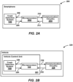
- FIGS 2A and 2B show examples of implementations that include crash detection systems according to embodiments of the present invention.
- Figure 2A shows a smartphone 200 that includes a crash detection system 100, a microprocessor 202, and communication circuitry 204.
- the microprocessor 202 includes at least one processor and at least one memory device storing processor-readable instructions that, when executed by the at least one processor to perform the functions of the microprocessor 202 described herein.
- the communication circuitry 204 includes a transmitter, a receiver, and an antenna.
- the transmitter and the receiver included in the communication circuitry 204 are configured to communicate according to cellular communication standards from the 3rd Generation Partnership Project (3GPP).
- 3GPP 3rd Generation Partnership Project
- the transmitter and the receiver included in the communication circuitry 204 are configured to communicate according to Long-Term Evolution (LTE) communication standards, which are fourth-generation (4G) wireless communication standards, and/or communicate according to a fifth-generation (5G) New Radio (NR) wireless communication standards.
- LTE Long-Term Evolution
- 4G fourth-generation
- NR New Radio
- the microprocessor 202 provides control signal(s) to the crash detection system 100, which are used to configure the crash detection system 100.
- the crash detection system 100 provides a crash event signal 208 to the microprocessor 202 when a crash event is detected.
- the microprocessor 202 provides signal(s) 210 to the communication circuitry 204.
- the signal(s) 210 causes the communication circuitry 204 to dial a telephone number that connects the smartphone 200 with a local medical center and/or emergency services, such as 911, for example.
- the signal(s) 210 may include voice data or other data (e.g. , text data that identifies a user of the smartphone 200).
- the smartphone 200 includes a location device (e.g. , GPS receiver) (not shown), and the signal(s) 210 include data indicating a location ( e.g. , latitude and longitude) of the smartphone 200.
- the communication circuitry 204 provides signal(s) 212 to the microprocessor 200.
- the signal(s) 212 may include audio and/or video data that is output to a speaker (not shown) and/or a display device (not shown) of the smartphone 200.
- Figure 2B shows a vehicle 220 that includes a vehicle control unit 221 with a crash detection system 100, a microprocessor 222, and communication circuitry 224.
- the vehicle 220 may be a motorcycle, an automobile, a boat, or an airplane, for example.
- the vehicle control unit 221 is connected to and controls various systems (not shown) of the vehicle 220.
- the microprocessor 222 and the communication circuitry 224 are similar in many relevant respects to the microprocessor 202 and the communication circuitry 204 discussed above.
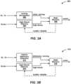
- FIGS 3A and 3B show examples of block diagrams for portions of crash detection systems according to embodiments of the present invention.
- the activity recognition block 302 is implemented in a machine learning core (MLC) (e.g. , running at 30 Hz) of the sensor 102B
- MLC machine learning core
- the high shock detector block 304 is implemented in a finite state machine (FSM) (e.g., running at 960 Hz) of the sensor 102B
- the state machine block 306 is implemented in a finite state machine (FSM) (e.g ., running at 960 Hz) of the sensor 102B.
- MLC machine learning core
- FSM finite state machine
- FSM finite state machine
- variance, peak to peak, and peak detector features can be computed based on accelerometer norm and norm 2 signal on a predetermined time window (e.g., a time window of 60 samples, corresponding to 2 seconds).
- decision tree training is performed on approximately 90 hours of collected logs, wherein a class "other" includes user stationary, walking (normal, slow, fast, stairs), running (jogging, sprinting), biking scenarios, and a class "driving” includes a user driving a car scenario.
- a very compact decision tree can be used to avoid overfitting.
- the total current consumption of the sensor 102B is approximately 200 microamperes ( ⁇ A), wherein the current consumption of an accelerometer operating in normal mode is approximately 110 ⁇ A, the current consumption of the MLC is approximately 5 ⁇ A, and the current consumption of the FSM is approximately 85 ⁇ A.
- sensor data XL / G from an accelerometer and/or a gyroscope included in a sensor is received, wherein the sensor data XL / G includes a value of linear acceleration (e.g ., specified in digits/g) for each axis of the accelerometer and/or a value of angular velocity ( e.g. , specified in digits/deg/s) for each axis of the gyroscope included in the sensor.
- linear acceleration e.g ., specified in digits/g
- angular velocity e.g. , specified in digits/deg/s
- AI artificial intelligence
- the smartphone 200 including the crash detection system 100 is used in a variety of experiments in which the sensor data XL / G is augmented to include indications of whether or not the smartphone is being used while driving, and statistical methods are used to train algorithms to classify whether the sensor data XL / G indicates the other than driving or the driving class.
- sensor data XLsec from an accelerometer included in a sensor is received, wherein the sensor data XLsec includes a value of linear acceleration for each axis of the accelerometer included in the sensor.
- the sensor is configured to verify if at least one of the values of the sensor data XLsec exceeds a threshold value (e.g., 30 g).
- the sensor is configured to continuously output the sensor data XLsec, and a processor determines if at least one of the values of the sensor data XLsec exceeds the threshold value.
- the same threshold value may be used for each axis of the accelerometer or different threshold values may be used for the axes of the accelerometer.
- a high shock signal is provided to the state machine block 306 if the sensor data XLsec indicates that a high shock event (e.g., a value of linear acceleration for at least one axis of the accelerometer exceeds the threshold value) has been detected.
- a check may be implemented on each of the axes of the accelerometer sensor data.
- the high shock signal is provided to the state machine block 306 if at least one of the accelerometer axis exceeds a configurable threshold (e.g., 15 g).
- a check may be implemented on the norm of the accelerometer sensor data.
- the high shock signal is provided to the state machine block 306 if the norm of the accelerometer data exceeds a configurable threshold (e.g ., 25 g). Thresholds may be higher when using a high-g accelerometer sensor ( e.g. , sensor 104A).
- a finite state machine is implemented based on the signals output by the activity recognition block 302 and the high shock detector block 304.
- an enable / disable signal is output to the high shock detector block 304. If the signal output by the activity recognition block 302 indicates the other than driving class, the enable / disable signal has a state ( e.g. , first voltage level or value) indicating that the high shock detector block 304 is disabled. If the signal output by the activity recognition block 302 indicates the driving class, the enable / disable signal has a state ( e.g. , second voltage level or value) indicating that the high shock detector block 304 is enabled.
- the enable / disable signal indicates that the high shock detector block 304 is disabled, the high shock detector block 304 does not output the high shock signal. While the enable / disable signal indicates that the high shock detector block 304 is enabled, the high shock detector block 304 outputs the high shock signal if a high shock event is detected.
- the state machine block 306 if the signal output by the activity recognition block 302 indicates the driving class while the signal output by the high shock detector block 304 indicates a high shock event, a determination is made whether the signal output by the activity recognition block 302 changes to indicate the other than driving class within a predetermined period of time. If the signal output by the activity recognition block 302 changes to indicate the other than driving class within the predetermined period of time, a crash event signal is output. If the signal output by the activity recognition block 302 does not change to indicate the other than driving class within the predetermined period of time, the crash event signal is not output.
- FIG 3B shows a block diagram 310 of a processor (e.g., microprocessor 106A or microcontroller 106B or 106C) used in an embodiment of a crash detection system 100 for a vehicle, such as the vehicle 220 shown in Figure 2B .
- the block diagram 310 includes a vehicle stationary detection block 312, a high shock detector block 314, and a state machine block 316.
- the vehicle stationary detection block 312 is similar in many relevant respects to the activity recognition block 302 described above except that, in the vehicle stationary detection block 312, a determination is made whether the sensor data XL / G indicates a stationary class or a moving class, and a signal indicating whether the sensor data is classified as the stationary class or the moving class is output to the state machine block 316.
- the high shock detector block 314 is similar in many relevant respects to the high shock detector block 304 described above.
- the state machine block 316 is similar in many relevant respects to the state machine block 306 described above except that, in the state machine block 316, if the signal output by the vehicle stationary detection block 312 indicates the moving class while the signal output by the high shock detector block 314 indicates a high shock event, a determination is made whether the signal output by the vehicle stationary detection block 312 changes to indicate the stationary class within a predetermined period of time. If the signal output by the vehicle stationary detection block 312 changes to indicate the stationary class within the predetermined period of time, a crash event signal is output. If the signal output by the vehicle stationary detection block 312 does not change to indicate the stationary class within the predetermined period of time, the crash event signal is not output.
- the state machine block 316 is explained in greater detail below in connection with Figure 5 .
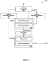
- FIG 4 shows an example of a finite state machine 400 used by a crash detection system according to an embodiment of the present invention.
- the finite state machine 400 corresponds to the block diagram 300 shown in Figure 3A .
- the finite state machine 400 is in an activity recognition state 402 in which the processing of the activity recognition block 302 is performed.
- the finite state machine 400 transitions to an enable high shock detector state 404 in which the signal output by the state machine block 306 indicates that the high shock detector block 304 is enabled.
- the finite state machine 400 then transitions to an activity recognition processing and high shock detector state 406 in which the processing of the activity recognition block 302 and the processing of the high shock detector block 304 are performed.
- the finite state machine 400 transitions to a disable high shock detector state 408 in which the signal output by the state machine block 306 indicates that the high shock detector block 304 is disabled.
- the finite state machine 400 then transitions back to the activity recognition state 402.
- the finite state machine 400 While the finite state machine 400 is in the activity recognition processing and high shock detector state 406, if the signal output by the activity recognition block 302 does not change to indicate the other than driving class, and the signal output by the high shock detector block 304 indicates a high shock event, the finite state machine 400 transitions to a start timer state 410 in which a timer is started.
- the finite state machine 400 then transitions to a check timer and activity recognition state 412 in which processing is performed that periodically checks the timer to determine whether the timer has reached a timeout value (e.g., 15 seconds) and the processing of the activity recognition block 302 is performed.
- a timeout value e.g. 15 seconds
- the timeout value must be higher than the latency required by the activity recognition block 302 to detect the other than driving class (e.g., 10 seconds).
- the finite state machine 400 While the finite state machine 400 is in the check timer and activity recognition state 412, if the timer reaches the timeout value, the finite state machine 400 transitions to the disable high shock detector state 408, and then transitions to the activity recognition state 402.
- a signal indicating a crash event is output to the microprocessor 202, which causes the microprocessor 202 to place a call to emergency services via communication circuity 204 and request assistance, for example.
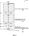
- FIG 5 shows an example of a finite state machine 500 used by a crash detection system according to an embodiment of the present invention.
- the finite state machine 500 corresponds to the block diagram 310 shown in Figure 3B .
- the finite state machine 500 is in a vehicle stationary detection state 502 in which the processing of the vehicle stationary detection block 312 is performed.
- the finite state machine 500 transitions to an enable high shock detector state 504 in which the signal output by the state machine block 316 indicates that the high shock detector block 314 is enabled.
- the finite state machine 500 then transitions to a vehicle stationary detection processing and high shock detector state 506 in which the processing of the vehicle stationary detection block 312 and the processing of the high shock detector block 314 are performed.
- the finite state machine 500 transitions to a disable high shock detector state 508 in which the signal output by the state machine block 316 indicates that the high shock detector block 314 is disabled.
- the finite state machine 500 then transitions back to the vehicle stationary detection state 502.
- the finite state machine 500 While the finite state machine 500 is in the vehicle stationary detection processing and high shock detector state 506, if the signal output by the vehicle stationary detection block 312 does not changes to indicate the stationary class, and the signal output by the high shock detector block 314 indicates a high shock event, the finite state machine 500 transitions to a start timer state 510 in which a timer is started.
- the finite state machine 500 then transitions to a check timer and vehicle stationary detection state 512 in which processing is performed that periodically checks the timer to determine whether the timer has reached a timeout value (e.g., 15 seconds) and the processing of the vehicle stationary detection block 312 is performed.
- the timeout value must be higher than the latency required by the vehicle stationary detection block 312 to detect the stationary class ( e.g. , 10 seconds).
- the finite state machine 500 While the finite state machine 500 is in the check timer and vehicle stationary detection state 512, if the timer reaches the timeout value, the finite state machine 500 transitions to the disable high shock detector state 508, and then transitions to the vehicle stationary detection state 502.
- a signal indicating a crash event is output to the microprocessor 222, which causes the microprocessor 222 to place a call to emergency services via the communication circuity 224 and request assistance, for example.
- Figure 6 shows an example of a processing flow 600 in a crash detection system according to an embodiment of the present invention.
- the processing flow 600 also includes processing 604 in which the signal output by the state machine block 306 indicates that the high shock detector block 304 is enabled, and the signal output by the activity recognition block 302 is checked to determine whether it indicates the other than driving class to disable the high shock detector block 304 and to reset the processing flow 600.
- processing flow 600 includes processing 606 in which a timer is started and the signal output by the activity recognition block 302 is checked to determine whether it indicates the other than driving class before timer reaches a configured timeout value.
- processing flow 600 includes processing 608 in which a crash event signal is output.
Landscapes
- Engineering & Computer Science (AREA)
- Mechanical Engineering (AREA)
- Traffic Control Systems (AREA)
Abstract
A crash detection system (100) includes first (102A; 102B; 102C) and second (104A; 104B; 104C) sensors and a processor (106A; 106B; 106C). The processor receives first sensor data (110A; 1 10B; 110C) output by the first sensor, determines whether the first sensor data indicates a first class or a second class, outputs an enable signal (112A; 112B; 112C) to the second sensor if the first sensor data indicates the second class, receives second sensor data (114A; 114B; 114C) output by the second sensor after the enable signal is output, determines whether the second sensor data indicates a high acceleration value, determines whether the first sensor data indicates the first class within a predetermined amount of time after the second sensor data is determined to indicate the high acceleration value, and outputs a signal indicating a crash has occurred in response to determining that the first sensor data indicates the first class within the predetermined amount of time after the second sensor data is determined to indicate the high acceleration value.
Description
- The present invention relates generally to crash detection systems, and more particularly to crash detection systems that can detect a crash without receiving input from external devices.
- Conventionally, a Car Crash Detection (CCD) feature is used to automatically help a user in the event that the user is involved in a car accident. For example, a CCD feature typically calls for medical help if a car accident is detected.
- Existing car crash detection systems use a so-called "high-g" accelerometer in order to measure peak acceleration that results from an accident, which could reach more than 100 g (i.e., one hundred times the force of gravity). Also, existing car crash detection systems included in smartphone devices use information that comes from multiple external devices, including a Global Positioning System (GPS) receiver, a plurality of motion sensors, and a microphone. For example, an existing car crash detection system uses location information from a GPS receiver to determine whether a vehicle (e.g., an automobile) is moving, uses data from the motion sensors to evaluate a peak acceleration during an impact from an accident, and uses data from the microphone to capture audio signal of the accident. If the GPS receiver is not able to receive a GPS signal from a GPS satellite, existing car crash detection systems may not be able to determine whether the vehicle is moving and, thus, may not be able to determine whether an accident has occurred. If an existing car crash detection system is operating on a smartphone that is kept highly isolated from a surrounding environment (e.g., in a pocket of a user), the existing car crash detection system may not be able to obtain audio data indicating that an accident has occurred. Accordingly, existing car crash detection systems rely on signals received from external devices, which might not always be available or might not always be ideal for car crash detection.
- In addition, existing car crash detection systems fuse information at a system level (e.g., Android service). Accordingly, existing car crash detection systems consume a relatively large amount of power.
- An aim of the invention is to overcome the problems of the prior art.
- According to the invention, a crash detection system, a method of operating the crash detection system and a non-transitory processor-readable storage medium are provided, as defined by the claims that are integral part of the present description.
- In particular, the disclosed crash detection system, method of operating the crash detection system and non-transitory processor-readable storage medium do not rely on signals received from external devices and, therefore, do not suffer from the drawbacks of conventional CCD systems discussed above. Additionally, they enable less power to be consumed than is consumed by conventional CCD systems.
- Non-limiting and non-exhaustive embodiments are described with reference to the following drawings. In the drawings, like reference numerals refer to like parts throughout the various figures unless otherwise specified.
- For a better understanding of the present invention, reference will be made to the following detailed description, which is to be read in association with the accompanying drawings:
-
Figures 1A, 1B, and 1C show examples of crash detection systems according to embodiments of the present invention. -
Figures 2A and 2B show examples of implementations that include crash detection systems according to embodiments of the present invention. -
Figures 3A and 3B show examples of block diagrams for portions of crash detection systems according to embodiments of the present invention. -
Figure 4 shows an example of a finite state machine used by a crash detection system according to an embodiment of the present invention. -
Figure 5 shows another example of a finite state machine used by a crash detection system according to an embodiment of the present invention. -
Figure 6 shows an example of a processing flow in a crash detection system according to an embodiment of the present invention. - Embodiments according to the present invention may use a combination of activity recognition based on motions sensor data, high shock detection based and accelerometer data, and a state machine. In order to detect a crash event, a high shock must be detected when an activity recognition block (or a vehicle stationary detection block) is detecting a "driving" class (or a "moving" class). A high shock detector block is enabled when needed in order to save power. After an accident, a vehicle suddenly becomes stationary. Therefore, the activity recognition block (or the vehicle stationary detection block) will detect an "other" class (or a "stationary" class). After the high shock is detected, a timer is started to give enough time to the activity recognition block (or the vehicle stationary detection block) to detect the "other" class (or the "stationary" class). If the timer reaches a timeout value, which is higher than a latency required by the activity recognition block to detect the "other" class or by the vehicle stationary detection block to detect the "stationary" class, the high-shock event is discarded because it is considered as a false positive.
-
Figures 1A, 1B, and 1C show examples of crash detection systems according to embodiments of the present invention. - More particularly,
Figure 1A shows an example of acrash detection system 100A including anintegrated circuit device 101A with asensor 102A, anintegrated circuit device 103A with asensor 104A, and anintegrated circuit device 105A with amicroprocessor 106A. The firstintegrated circuit device 101A, theintegrated circuit device 103A, and theintegrated circuit device 105A are different from each other. - The
microprocessor 106A provides control signal(s) 108A to thesensor 102A, for example, including a control signal that causes thesensor 102A to enter a sleep state, a control signal that causes thesensor 102A to wake up or exit the sleep state, and a control signal that sets one or more detection thresholds in thesensor 102A. - The
sensor 102A provides data signal(s) 110A to themicroprocessor 106A, for example, including sensor data for each axis of a first accelerometer, a second accelerometer, and/or a gyroscope included in thesensor 102A. In one or more embodiments, thesensor 102A provides sensor data at a relatively low rate, for example, a rate that is greater than or equal to 25 Hertz (Hz) (i.e., 25 times per second). - The
microprocessor 106A provides control signal(s) 112A to thesensor 104A, for example, including a control signal that causes thesensor 104A to enter a sleep state, a control signal that causes thesensor 104A to wake up or exit the sleep state, and a control signal that sets one or more detection thresholds in thesensor 104A. - The
sensor 104A provides data signal(s) 114A to themicroprocessor 106A, for example, including sensor data for each axis of a first accelerometer, a second accelerometer, and/or a gyroscope included in thesensor 104A. In one or more embodiments, thesensor 104A provides sensor data at a relatively high rate, for example, a rate that is greater than or equal to 400 Hz (i.e., 400 times per second). - The
microprocessor 106A includes at least one processor and at least one memory device storing processor-readable instructions that, when executed by the at least one processor to perform the functions of themicroprocessor 106A described herein, which are explained below in connection withFigures 2A, 2B ,3A, 3B ,4 ,5 , and6 . - In one or more embodiments, the
sensor 102A is a model number LSM6DSV16X 6-axis inertial measurement unit (IMU) from STMicroelectronics or a model number LIS2DUX12 ultralow-power accelerometer from STMicroelectronics. In one or more embodiments, thesensor 104A is a model number H3LIS331DL high-g, low-power 3-axis digital accelerometer from STMicroelectronics. In one or more embodiments, themicroprocessor 106A is a model number STM32MP1 microprocessor from STMicroelectronics. Other models of devices may be used for thesensor 102A, thesensor 104A, and themicroprocessor 106A within the scope of the present invention. -
Figure 1B shows an example of acrash detection system 100B including anintegrated circuit device 101B with asensor 102B and amicrocontroller 106B, and anintegrated circuit device 103B with asensor 104B. Thecrash detection system 100B shown inFigure 1B is similar in many relevant respects to thecrash detection system 100A shown inFigure 1A , except that thesensor 102B and themicrocontroller 106B are included in the same integratedcircuit device 101B, and thesensor 104B is included in theintegrated circuit device 103B, which is different from theintegrated circuit device 101B. - The
sensor 102B and thesensor 104B are similar in many relevant respects to thesensor 102A and thesensor 104A described above. In one or more embodiments, themicrocontroller 106B is used to implement a Machine Learning Core (MLC) or a Finite State Machine (FSM) of the integratedcircuit device 101B. In another embodiment, themicrocontroller 106B is an Intelligent Sensor Processing Unit (ISPU) of the integratedcircuit device 101B. - The
microcontroller 106B provides control signal(s) 108B to thesensor 102B, which are similar to the control signal(s) 108A described above. - The
sensor 102B provides data signal(s) 110B to themicrocontroller 106B, which are similar to the control signal(s) 110A described above. - The
microcontroller 106B provides control signal(s) 112B to thesensor 104B, which are similar to the control signal(s) 112A described above. - The
sensor 104B provides data signal(s) 114B to themicrocontroller 106B, which are similar to the control signal(s) 114A described above. - The
microcontroller 106B includes at least one processor and at least one memory device storing processor-readable instructions that, when executed by the at least one processor to perform the functions of themicrocontroller 106B described herein, which are explained below in connection withFigures 2A, 2B ,3A, 3B ,4 ,5 , and6 . -
Figure 1C shows an example of acrash detection system 100C including anintegrated circuit device 101C with asensor 102C, asensor 104C, and amicrocontroller 106C. Thecrash detection system 100C shown inFigure 1C is similar in many relevant respects to thecrash detection system 100A shown inFigure 1A and thecrash detection system 100B shown inFigure 1B , except that thesensor 102C, thesensor 104C, and themicrocontroller 106C are included in the sameintegrated circuit device 101C. - The
sensor 102C and thesensor 104C are similar in many relevant respects to thesensor 102A and thesensor 104A described above. In one or more embodiments, themicrocontroller 106C is used to implement a Machine Learning Core (MLC) or a Finite State Machine (FSM) of the integratedcircuit device 101C. In another embodiment, themicrocontroller 106C is an Intelligent Sensor Processing Unit (ISPU) of theintegrated circuit device 101C. - The
microcontroller 106C provides control signal(s) 108C to thesensor 102C, which are similar to the control signal(s) 108A described above. - The
sensor 102C provides data signal(s) 110C to themicrocontroller 106C, which are similar to the control signal(s) 110A described above. - The
microcontroller 106C provides control signal(s) 112C to thesensor 104C, which are similar to the control signal(s) 112A described above. - The
sensor 104C provides data signal(s) 114C to themicrocontroller 106C, which are similar to the control signal(s) 114A described above. - The
microcontroller 106C includes at least one processor and at least one memory device storing processor-readable instructions that, when executed by the at least one processor to perform the functions of themicrocontroller 106C described herein, which are explained below in connection withFigures 2A, 2B ,3A, 3B ,4 ,5 , and6 . - The
crash detection system 100A shown inFigure 1A , thecrash detection system 100B shown inFigure 1B , and thecrash detection system 100C shown inFigure 1C are referred to herein generally ascrash detection system 100 unless a particular one of those systems is being referenced. -
Figures 2A and 2B show examples of implementations that include crash detection systems according to embodiments of the present invention. - More particularly,
Figure 2A shows asmartphone 200 that includes acrash detection system 100, amicroprocessor 202, andcommunication circuitry 204. - The
microprocessor 202 includes at least one processor and at least one memory device storing processor-readable instructions that, when executed by the at least one processor to perform the functions of themicroprocessor 202 described herein. - The
communication circuitry 204 includes a transmitter, a receiver, and an antenna. In one or more embodiments, the transmitter and the receiver included in thecommunication circuitry 204 are configured to communicate according to cellular communication standards from the 3rd Generation Partnership Project (3GPP). For example, the transmitter and the receiver included in thecommunication circuitry 204 are configured to communicate according to Long-Term Evolution (LTE) communication standards, which are fourth-generation (4G) wireless communication standards, and/or communicate according to a fifth-generation (5G) New Radio (NR) wireless communication standards. - The
microprocessor 202 provides control signal(s) to thecrash detection system 100, which are used to configure thecrash detection system 100. - The
crash detection system 100 provides acrash event signal 208 to themicroprocessor 202 when a crash event is detected. - In response, the
microprocessor 202 provides signal(s) 210 to thecommunication circuitry 204. The signal(s) 210 causes thecommunication circuitry 204 to dial a telephone number that connects thesmartphone 200 with a local medical center and/or emergency services, such as 911, for example. In addition, the signal(s) 210 may include voice data or other data (e.g., text data that identifies a user of the smartphone 200). In one more embodiments, thesmartphone 200 includes a location device (e.g., GPS receiver) (not shown), and the signal(s) 210 include data indicating a location (e.g., latitude and longitude) of thesmartphone 200. - The
communication circuitry 204 provides signal(s) 212 to themicroprocessor 200. The signal(s) 212 may include audio and/or video data that is output to a speaker (not shown) and/or a display device (not shown) of thesmartphone 200. -
Figure 2B shows avehicle 220 that includes avehicle control unit 221 with acrash detection system 100, amicroprocessor 222, andcommunication circuitry 224. Thevehicle 220 may be a motorcycle, an automobile, a boat, or an airplane, for example. Thevehicle control unit 221 is connected to and controls various systems (not shown) of thevehicle 220. In one or more embodiments, themicroprocessor 222 and thecommunication circuitry 224 are similar in many relevant respects to themicroprocessor 202 and thecommunication circuitry 204 discussed above. -
Figures 3A and 3B show examples of block diagrams for portions of crash detection systems according to embodiments of the present invention. - More particularly,
Figure 3A shows a block diagram 300 of a processor (e.g.,microprocessor 106A ormicrocontroller crash detection system 100 for a smartphone, such as thesmartphone 200 shown inFigure 2A . The block diagram 300 includes anactivity recognition block 302, a highshock detector block 304, and astate machine block 306. - In one example, the
activity recognition block 302 is implemented in a machine learning core (MLC) (e.g., running at 30 Hz) of thesensor 102B, the highshock detector block 304 is implemented in a finite state machine (FSM) (e.g., running at 960 Hz) of thesensor 102B, and thestate machine block 306 is implemented in a finite state machine (FSM) (e.g., running at 960 Hz) of thesensor 102B. - In details, variance, peak to peak, and peak detector features can be computed based on accelerometer norm and norm2 signal on a predetermined time window (e.g., a time window of 60 samples, corresponding to 2 seconds).
- For example, decision tree training is performed on approximately 90 hours of collected logs, wherein a class "other" includes user stationary, walking (normal, slow, fast, stairs), running (jogging, sprinting), biking scenarios, and a class "driving" includes a user driving a car scenario. A very compact decision tree can be used to avoid overfitting.
- Experiments have been performed in which raw accuracy of approximately 91 % was achieved and meta-classified (5 consecutive windows, corresponding to 10 s) accuracy of approximately 94% was achieved. The total current consumption of the
sensor 102B is approximately 200 microamperes (µA), wherein the current consumption of an accelerometer operating in normal mode is approximately 110 µA, the current consumption of the MLC is approximately 5 µA, and the current consumption of the FSM is approximately 85 µA. - In the
activity recognition block 302, sensor data XL / G from an accelerometer and/or a gyroscope included in a sensor (e.g.,sensor activity recognition block 302, a determination is made whether the sensor data XL / G indicates an other than driving class or a driving class, and a signal indicating whether the sensor data is classified as the other than driving class or the driving class is output to thestate machine block 306. - In one or more embodiments, artificial intelligence (AI) techniques such as machine learning techniques are used in the
activity recognition block 302. For example, thesmartphone 200 including thecrash detection system 100 is used in a variety of experiments in which the sensor data XL / G is augmented to include indications of whether or not the smartphone is being used while driving, and statistical methods are used to train algorithms to classify whether the sensor data XL / G indicates the other than driving or the driving class. - In the high
shock detector block 304, sensor data XLsec from an accelerometer included in a sensor (e.g.,sensor - In the high
shock detector block 304, a high shock signal is provided to thestate machine block 306 if the sensor data XLsec indicates that a high shock event (e.g., a value of linear acceleration for at least one axis of the accelerometer exceeds the threshold value) has been detected. In one embodiment, a check may be implemented on each of the axes of the accelerometer sensor data. For example, using a triaxial accelerometer sensor, the high shock signal is provided to thestate machine block 306 if at least one of the accelerometer axis exceeds a configurable threshold (e.g., 15 g). In another embodiment, a check may be implemented on the norm of the accelerometer sensor data. For example, the high shock signal is provided to thestate machine block 306 if the norm of the accelerometer data exceeds a configurable threshold (e.g., 25 g). Thresholds may be higher when using a high-g accelerometer sensor (e.g.,sensor 104A). - In the
state machine block 306, a finite state machine is implemented based on the signals output by theactivity recognition block 302 and the highshock detector block 304. As explained in greater detail below in connection withFigure 4 , in thestate machine block 306, an enable / disable signal is output to the highshock detector block 304. If the signal output by theactivity recognition block 302 indicates the other than driving class, the enable / disable signal has a state (e.g., first voltage level or value) indicating that the highshock detector block 304 is disabled. If the signal output by theactivity recognition block 302 indicates the driving class, the enable / disable signal has a state (e.g., second voltage level or value) indicating that the highshock detector block 304 is enabled. While the enable / disable signal indicates that the highshock detector block 304 is disabled, the highshock detector block 304 does not output the high shock signal. While the enable / disable signal indicates that the highshock detector block 304 is enabled, the highshock detector block 304 outputs the high shock signal if a high shock event is detected. - In the
state machine block 306, if the signal output by theactivity recognition block 302 indicates the driving class while the signal output by the highshock detector block 304 indicates a high shock event, a determination is made whether the signal output by the activity recognition block 302 changes to indicate the other than driving class within a predetermined period of time. If the signal output by the activity recognition block 302 changes to indicate the other than driving class within the predetermined period of time, a crash event signal is output. If the signal output by theactivity recognition block 302 does not change to indicate the other than driving class within the predetermined period of time, the crash event signal is not output. -
Figure 3B shows a block diagram 310 of a processor (e.g.,microprocessor 106A ormicrocontroller crash detection system 100 for a vehicle, such as thevehicle 220 shown inFigure 2B . The block diagram 310 includes a vehiclestationary detection block 312, a highshock detector block 314, and astate machine block 316. - The vehicle
stationary detection block 312 is similar in many relevant respects to the activity recognition block 302 described above except that, in the vehiclestationary detection block 312, a determination is made whether the sensor data XL / G indicates a stationary class or a moving class, and a signal indicating whether the sensor data is classified as the stationary class or the moving class is output to thestate machine block 316. - The high
shock detector block 314 is similar in many relevant respects to the highshock detector block 304 described above. - The
state machine block 316 is similar in many relevant respects to the state machine block 306 described above except that, in thestate machine block 316, if the signal output by the vehiclestationary detection block 312 indicates the moving class while the signal output by the highshock detector block 314 indicates a high shock event, a determination is made whether the signal output by the vehiclestationary detection block 312 changes to indicate the stationary class within a predetermined period of time. If the signal output by the vehiclestationary detection block 312 changes to indicate the stationary class within the predetermined period of time, a crash event signal is output. If the signal output by the vehiclestationary detection block 312 does not change to indicate the stationary class within the predetermined period of time, the crash event signal is not output. Thestate machine block 316 is explained in greater detail below in connection withFigure 5 . -
Figure 4 shows an example of afinite state machine 400 used by a crash detection system according to an embodiment of the present invention. Thefinite state machine 400 corresponds to the block diagram 300 shown inFigure 3A . - Initially, the
finite state machine 400 is in anactivity recognition state 402 in which the processing of theactivity recognition block 302 is performed. - If the signal output by the
activity recognition block 302 indicates the driving class, thefinite state machine 400 transitions to an enable highshock detector state 404 in which the signal output by thestate machine block 306 indicates that the highshock detector block 304 is enabled. - The
finite state machine 400 then transitions to an activity recognition processing and highshock detector state 406 in which the processing of theactivity recognition block 302 and the processing of the highshock detector block 304 are performed. - If the signal output by the activity recognition block 302 changes to indicate the other than driving class, the
finite state machine 400 transitions to a disable highshock detector state 408 in which the signal output by thestate machine block 306 indicates that the highshock detector block 304 is disabled. - The
finite state machine 400 then transitions back to theactivity recognition state 402. - While the
finite state machine 400 is in the activity recognition processing and highshock detector state 406, if the signal output by theactivity recognition block 302 does not change to indicate the other than driving class, and the signal output by the highshock detector block 304 indicates a high shock event, thefinite state machine 400 transitions to astart timer state 410 in which a timer is started. - The
finite state machine 400 then transitions to a check timer andactivity recognition state 412 in which processing is performed that periodically checks the timer to determine whether the timer has reached a timeout value (e.g., 15 seconds) and the processing of theactivity recognition block 302 is performed. The timeout value must be higher than the latency required by theactivity recognition block 302 to detect the other than driving class (e.g., 10 seconds). - While the
finite state machine 400 is in the check timer andactivity recognition state 412, if the timer reaches the timeout value, thefinite state machine 400 transitions to the disable highshock detector state 408, and then transitions to theactivity recognition state 402. - If the timer does not reach the timeout value, and the signal output by the activity recognition block 302 changes to indicate the other than driving class, a signal indicating a crash event is output to the
microprocessor 202, which causes themicroprocessor 202 to place a call to emergency services viacommunication circuity 204 and request assistance, for example. -
Figure 5 shows an example of afinite state machine 500 used by a crash detection system according to an embodiment of the present invention. Thefinite state machine 500 corresponds to the block diagram 310 shown inFigure 3B . - Initially, the
finite state machine 500 is in a vehiclestationary detection state 502 in which the processing of the vehiclestationary detection block 312 is performed. - If the signal output by the vehicle
stationary detection block 312 indicates the moving class, thefinite state machine 500 transitions to an enable highshock detector state 504 in which the signal output by thestate machine block 316 indicates that the highshock detector block 314 is enabled. - The
finite state machine 500 then transitions to a vehicle stationary detection processing and highshock detector state 506 in which the processing of the vehiclestationary detection block 312 and the processing of the highshock detector block 314 are performed. - If the signal output by the vehicle
stationary detection block 312 changes to indicate the stationary class, thefinite state machine 500 transitions to a disable highshock detector state 508 in which the signal output by thestate machine block 316 indicates that the highshock detector block 314 is disabled. - The
finite state machine 500 then transitions back to the vehiclestationary detection state 502. - While the
finite state machine 500 is in the vehicle stationary detection processing and highshock detector state 506, if the signal output by the vehiclestationary detection block 312 does not changes to indicate the stationary class, and the signal output by the highshock detector block 314 indicates a high shock event, thefinite state machine 500 transitions to astart timer state 510 in which a timer is started. - The
finite state machine 500 then transitions to a check timer and vehiclestationary detection state 512 in which processing is performed that periodically checks the timer to determine whether the timer has reached a timeout value (e.g., 15 seconds) and the processing of the vehiclestationary detection block 312 is performed. The timeout value must be higher than the latency required by the vehiclestationary detection block 312 to detect the stationary class (e.g., 10 seconds). - While the
finite state machine 500 is in the check timer and vehiclestationary detection state 512, if the timer reaches the timeout value, thefinite state machine 500 transitions to the disable highshock detector state 508, and then transitions to the vehiclestationary detection state 502. - If the timer does not reach the timeout value, and the signal output by the vehicle
stationary detection block 312 changes to indicate the stationary class, a signal indicating a crash event is output to themicroprocessor 222, which causes themicroprocessor 222 to place a call to emergency services via thecommunication circuity 224 and request assistance, for example. -
Figure 6 shows an example of aprocessing flow 600 in a crash detection system according to an embodiment of the present invention. - The
processing flow 600 includes processing 602 in which the signal output by theactivity recognition block 302 is checked to determine whether it indicates the driving class. - The
processing flow 600 also includes processing 604 in which the signal output by thestate machine block 306 indicates that the highshock detector block 304 is enabled, and the signal output by theactivity recognition block 302 is checked to determine whether it indicates the other than driving class to disable the highshock detector block 304 and to reset theprocessing flow 600. - In addition, the
processing flow 600 includes processing 606 in which a timer is started and the signal output by theactivity recognition block 302 is checked to determine whether it indicates the other than driving class before timer reaches a configured timeout value. - Additionally, the
processing flow 600 includes processing 608 in which a crash event signal is output. - In view of the foregoing, the advantages of the crash detection system, the method of operating the crash detection system and the non-transitory processor-readable storage medium according to the invention are apparent.
- It is also clear that modifications can be made to the described crash detection system, method of operating the crash detection system and non-transitory processor-readable storage medium, which do not extend beyond the scope of protection defined by the claims.
- For example, the various embodiments described above can be combined to provide further embodiments. Example embodiments of the present invention are summarized here.
- Example 1. A crash detection system, comprising:
- a first sensor which, in operation, outputs first sensor data;
- a second sensor which, in operation, outputs second sensor data; and
- a processor coupled to the first sensor and the second sensor,
- wherein the processor, in operation:
- receives the first sensor data,
- determines whether the first sensor data indicates a first class or a second class,
- outputs an enable signal to the second sensor in response to determining that the first sensor data indicates the second class,
- receives the second sensor data after the enable signal is output to the second sensor,
- determines whether the second sensor data indicates a detected acceleration value that is greater than or equal to a threshold acceleration value,
- determines whether the first sensor data indicates the first class within a predetermined amount of time after the second sensor data is determined to indicate the detected acceleration value that is greater than or equal to the threshold acceleration value, and
- outputs a signal indicating a crash has occurred in response to determining that the first sensor data indicates the first class within the predetermined amount of time after the second sensor data is determined to indicate the detected acceleration value that is greater than or equal to the threshold acceleration value.
- Example 2. The crash detection system according to example 1, wherein the processor, in operation, does not output the signal indicating the crash has occurred in response to determining that the first sensor data indicates the second class within the predetermined amount of time after the second sensor data is determined to indicate the detected acceleration value that is greater than or equal to the threshold acceleration value.
- Example 3. The crash detection system according to example 1, wherein:
- the second sensor operates while the enable signal is output by the processor, and
- the second sensor does not operate while the enable signal is not output by the processor.
- Example 4. The crash detection system according to example 1, wherein:
- the first sensor outputs the first sensor data at a first rate,
- the second sensor outputs the second sensor data at a second rate, and the second rate is greater than the first rate.
- Example 5. The crash detection system according to example 1, wherein:
- the first sensor is included in a first integrated circuit device,
- the second sensor is included in a second integrated circuit device that is different from the first integrated circuit device, and
- the processor is in a third integrated circuit device that is different from the first integrated circuit device and the second integrated circuit device.
- Example 6. The crash detection system according to example 1, wherein:
- the first sensor and the processor are included in a first integrated circuit device, and
- the second sensor is included in a second integrated circuit device that is different from the first integrated circuit device.
- Example 7. The crash detection system according to example 1, wherein the first sensor, the second sensor, and the processor are included in a same integrated circuit device.
- Example 8. The crash detection system according to example 1, wherein:
- the first sensor includes a first accelerometer,
- the second sensor includes a second accelerometer, and
- the second accelerometer, in operation, detects a larger amount of acceleration than the first accelerometer.
- Example 9. The crash detection system according to example 8, wherein the first sensor includes a gyroscope, and wherein the first sensor data includes output from the first accelerometer and output from the gyroscope.
- Example 10. The crash detection system according to example 1, wherein the first class is an other than driving class and the second class is a driving class, or the first class is a stationary class and the second class is a moving class.
- Example 11. A method of operating a crash detection system, the method comprising:
- receiving, by a processor, first sensor data output by a first sensor;
- determining, by the processor, whether the first sensor data indicates a first class or a second class;
- outputting, by the processor, an enable signal to a second sensor in response to determining that the first sensor data indicates the second class;
- receiving, by the processor, second sensor data output by the second sensor after the enable signal is output to the second sensor;
- determining, by the processor, whether the second sensor data indicates a detected acceleration value that is greater than or equal to a threshold acceleration value;
- determining, by the processor, whether the first sensor data indicates the first class within a predetermined amount of time after the second sensor data is determined to indicate the detected acceleration value that is greater than or equal to the threshold acceleration value; and
- outputting, by the processor, a signal indicating a crash has occurred in response to determining that the first sensor data indicates the first class within the predetermined amount of time after the second sensor data is determined to indicate the detected acceleration value that is greater than or equal to the threshold acceleration value.
- Example 12. The method according to example 11, further comprising:
- determining, by the processor, that the first sensor data indicates the second class within the predetermined amount of time after the second sensor data is determined to indicate the detected acceleration value that is greater than or equal to the threshold acceleration value,
- wherein the processor does not output the signal indicating the crash has occurred in response to the determining that the first sensor data indicates the second class within the predetermined amount of time after the second sensor data is determined to indicate the detected acceleration value that is greater than or equal to the threshold acceleration value.
- Example 13. The method according to example 11, further comprising:
- operating, by the second sensor, while the enable signal is output by the processor,
- wherein the second sensor does not operate while the enable signal is not output by the processor.
- Example 14. The method according to example 11, further comprising:
- outputting, by the first sensor, the first sensor data at a first rate; and
- outputting, by the second sensor, the second sensor data at a second rate,
- wherein the second rate is greater than the first rate.
- Example 15. The method according to example 11, wherein:
- detecting, by a first accelerometer included in the first sensor, a first amount of acceleration; and
- detecting, by a second accelerometer included in the second sensor, a second amount of acceleration,
- wherein the second amount of acceleration is greater than the first amount of acceleration.
- Example 16. The crash detection system according to example 15, wherein the first sensor includes a gyroscope, and wherein the first sensor data includes output from the first accelerometer and output from the gyroscope.
- Example 17. The method according to example 11, wherein the first class is an other than driving class and the second class is a driving class, or the first class is a stationary class and the second class is a moving class.
- Example 18. A non-transitory processor-readable storage medium storing instructions that, when executed by a processor, cause the processor to:
- determine whether first sensor data output by a first sensor indicates a first class or a second class,
- output an enable signal to a second sensor in response to determining that the first sensor data indicates the second class,
- determine whether second sensor data output by the second sensor after the enable signal is output to the second sensor indicates a detected acceleration value that is greater than or equal to a threshold acceleration value,
- determine whether the first sensor data indicates the first class within a predetermined amount of time after the second sensor data is determined to indicate the detected acceleration value that is greater than or equal to the threshold acceleration value, and
- output a signal indicating a crash has occurred in response to determining that the first sensor data indicates the first class within the predetermined amount of time after the second sensor data is determined to indicate the detected acceleration value that is greater than or equal to the threshold acceleration value.
- Example 19. The storage medium according to example 11, wherein the instructions, when executed by a processor, cause the processor to:
- determine that the first sensor data indicates the second class within the predetermined amount of time after the second sensor data is determined to indicate the detected acceleration value that is greater than or equal to the threshold acceleration value,
- wherein the processor does not output the signal indicating the crash has occurred if the first sensor data is determined to indicate the second class within the predetermined amount of time after the second sensor data is determined to indicate the detected acceleration value that is greater than or equal to the threshold acceleration value.
- Example 20. The storage medium according to example 11, wherein the first class is an other than driving class and the second class is a driving class, or the first class is a stationary class and the second class is a moving class.
Claims (14)
- A crash detection system (100), comprising:a first sensor (102A; 102B; 102C) which is configured to output first sensor data (110A; 110B; 110C);a second sensor (104A; 104B; 104C) which is configured to output second sensor data (114A; 114B; 114C); anda processor (106A; 106B; 106C) coupled to the first sensor and the second sensor,wherein the processor is configured to:receive the first sensor data,determine whether the first sensor data indicates a first class or a second class,output an enable signal (112A; 112B; 112C) to the second sensor in response to determining that the first sensor data indicates the second class,receive the second sensor data after the enable signal is output to the second sensor,determine whether the second sensor data indicates a detected acceleration value that is greater than or equal to a threshold acceleration value,determine whether the first sensor data indicates the first class within a predetermined amount of time after the second sensor data is determined to indicate the detected acceleration value that is greater than or equal to the threshold acceleration value, andoutput a signal indicating a crash has occurred in response to determining that the first sensor data indicates the first class within the predetermined amount of time after the second sensor data is determined to indicate the detected acceleration value that is greater than or equal to the threshold acceleration value.
- The crash detection system according to claim 1, wherein the processor is configured to do not output the signal indicating the crash has occurred in response to determining that the first sensor data indicates the second class within the predetermined amount of time after the second sensor data is determined to indicate the detected acceleration value that is greater than or equal to the threshold acceleration value.
- The crash detection system according to claim 1 or 2, wherein:the second sensor is configured to operate while the enable signal is output by the processor, andthe second sensor is configured to do not operate while the enable signal is not output by the processor.
- The crash detection system according to anyone of the previous claims, wherein one of the following applies:the first sensor is configured to output the first sensor data at a first rate,the second sensor is configured to output the second sensor data at a second rate, andthe second rate is greater than the first rate;
orthe first sensor is included in a first integrated circuit device (101A),the second sensor is included in a second integrated circuit device (103A) that is different from the first integrated circuit device, andthe processor is in a third integrated circuit device (105A) that is different from the first integrated circuit device and the second integrated circuit device;
orthe first sensor and the processor are included in a first integrated circuit device (101B), andthe second sensor is included in a second integrated circuit device (103B) that is different from the first integrated circuit device. - The crash detection system according to anyone of the previous claims, wherein the first sensor, the second sensor and the processor are included in a same integrated circuit device (101C).
- The crash detection system according to anyone of the previous claims, wherein:the first sensor includes a first accelerometer,the second sensor includes a second accelerometer, andthe second accelerometer is configured to detect a larger amount of acceleration than the first accelerometer.
- The crash detection system according to claim 6, wherein the first sensor includes a gyroscope, and wherein the first sensor data includes output from the first accelerometer and output from the gyroscope.
- A method of operating a crash detection system (100), the method comprising:receiving, by a processor (106A; 106B; 106C), first sensor data (110A; 110B; 110C) output by a first sensor (102A; 102B; 102C);determining, by the processor, whether the first sensor data indicates a first class or a second class;outputting, by the processor, an enable signal (112A; 112B; 112C) to a second sensor in response to determining that the first sensor data indicates the second class;receiving, by the processor, second sensor data (114A; 114B; 114C) output by the second sensor (104A; 104B; 104C) after the enable signal is output to the second sensor;determining, by the processor, whether the second sensor data indicates a detected acceleration value that is greater than or equal to a threshold acceleration value;determining, by the processor, whether the first sensor data indicates the first class within a predetermined amount of time after the second sensor data is determined to indicate the detected acceleration value that is greater than or equal to the threshold acceleration value; andoutputting, by the processor, a signal indicating a crash has occurred in response to determining that the first sensor data indicates the first class within the predetermined amount of time after the second sensor data is determined to indicate the detected acceleration value that is greater than or equal to the threshold acceleration value.
- The method according to claim 8, further comprising:determining, by the processor, that the first sensor data indicates the second class within the predetermined amount of time after the second sensor data is determined to indicate the detected acceleration value that is greater than or equal to the threshold acceleration value,wherein the signal indicating the crash has occurred is not output by the processor in response to the determining that the first sensor data indicates the second class within the predetermined amount of time after the second sensor data is determined to indicate the detected acceleration value that is greater than or equal to the threshold acceleration value.
- The method according to claim 8 or 9, further comprising:operating, by the second sensor, while the enable signal is output by the processor,wherein the second sensor is not operated while the enable signal is not output by the processor.
- The method according to anyone of claims 8-10, further comprising:outputting, by the first sensor, the first sensor data at a first rate; andoutputting, by the second sensor, the second sensor data at a second rate,wherein the second rate is greater than the first rate.
- The method according to anyone of claims 8-11, wherein:detecting, by a first accelerometer included in the first sensor, a first amount of acceleration; anddetecting, by a second accelerometer included in the second sensor, a second amount of acceleration,wherein the second amount of acceleration is greater than the first amount of acceleration.
- The method according to anyone of claims 8-12, wherein the first class is an other than driving class and the second class is a driving class, or the first class is a stationary class and the second class is a moving class.
- A non-transitory processor-readable storage medium storing instructions that, when executed by a processor (106A; 106B; 106C), cause the processor to:determine whether first sensor data (110A; 1 10B; 110C) output by a first sensor (102A; 102B; 102C) indicates a first class or a second class,output an enable signal (112A; 112B; 112C) to a second sensor in response to determining that the first sensor data indicates the second class,determine whether second sensor data (114A; 114B; 114C) output by the second sensor (104A; 104B; 104C) after the enable signal is output to the second sensor indicates a detected acceleration value that is greater than or equal to a threshold acceleration value,determine whether the first sensor data indicates the first class within a predetermined amount of time after the second sensor data is determined to indicate the detected acceleration value that is greater than or equal to the threshold acceleration value, andoutput a signal indicating a crash has occurred in response to determining that the first sensor data indicates the first class within the predetermined amount of time after the second sensor data is determined to indicate the detected acceleration value that is greater than or equal to the threshold acceleration value.
Applications Claiming Priority (1)
| Application Number | Priority Date | Filing Date | Title |
|---|---|---|---|
| US18/317,795 US12479383B2 (en) | 2023-05-15 | 2023-05-15 | In-sensor crash detection with motion sensors |
Publications (1)
| Publication Number | Publication Date |
|---|---|
| EP4467399A1 true EP4467399A1 (en) | 2024-11-27 |
Family
ID=90924032
Family Applications (1)
| Application Number | Title | Priority Date | Filing Date |
|---|---|---|---|
| EP24172992.0A Pending EP4467399A1 (en) | 2023-05-15 | 2024-04-29 | In-sensor crash detection with motion sensors |
Country Status (3)
| Country | Link |
|---|---|
| US (1) | US12479383B2 (en) |
| EP (1) | EP4467399A1 (en) |
| CN (1) | CN118953265A (en) |
Citations (5)
| Publication number | Priority date | Publication date | Assignee | Title |
|---|---|---|---|---|
| DE102004057689A1 (en) * | 2004-11-30 | 2006-06-08 | Robert Bosch Gmbh | Restraint system controlling method for motor vehicle, involves adjusting two threshold values to detect and plausibilize collision process based on detected condition, and plausibilizing collision process with sensor and evaluation unit |
| US10292064B2 (en) * | 2016-03-09 | 2019-05-14 | Qualcomm Incorporated | Detection and reporting of a collision event |
| US20220207987A1 (en) * | 2020-12-29 | 2022-06-30 | Hyundai Motor Company | Vehicle and method for controlling an emergency call therefor |
| US20230085552A1 (en) * | 2020-01-31 | 2023-03-16 | Robert Bosch Gmbh | Method and device for checking the plausibility of an accident involving a two-wheeled vehicle |
| US20230109452A1 (en) * | 2016-04-22 | 2023-04-06 | State Farm Mutual Automobile Insurance Company | System and Method for Indicating Whether a Vehicle Crash Has Occurred |
Family Cites Families (9)
| Publication number | Priority date | Publication date | Assignee | Title |
|---|---|---|---|---|
| JP4387287B2 (en) | 2004-11-05 | 2009-12-16 | 三菱電機株式会社 | Vehicle accident analysis device |
| US8527140B2 (en) | 2009-02-10 | 2013-09-03 | Roy Schwartz | Vehicle state detection |
| US9776589B2 (en) | 2014-06-26 | 2017-10-03 | GM Global Technology Operations LLC | Vehicle control system and method of using the same |
| US9392431B2 (en) * | 2014-09-30 | 2016-07-12 | Verizon Patent And Licensing Inc. | Automatic vehicle crash detection using onboard devices |
| US10083551B1 (en) | 2015-04-13 | 2018-09-25 | Allstate Insurance Company | Automatic crash detection |
| EP3652721A1 (en) | 2017-09-04 | 2020-05-20 | NNG Software Developing and Commercial LLC | A method and apparatus for collecting and using sensor data from a vehicle |
| US11699306B2 (en) * | 2019-08-16 | 2023-07-11 | Cambridge Mobile Telematics, Inc. | Method and system for vehicle speed estimation |
| US11841231B2 (en) | 2021-05-25 | 2023-12-12 | Cambridge Mobile Telematics Inc. | Method and system for vehicle route determination based on motion data |
| US12384272B2 (en) * | 2022-12-16 | 2025-08-12 | Infineon Technologies Ag | Air bag sensor for vehicle protection during parking mode |
-
2023
- 2023-05-15 US US18/317,795 patent/US12479383B2/en active Active
-
2024
- 2024-04-29 EP EP24172992.0A patent/EP4467399A1/en active Pending
- 2024-05-13 CN CN202410588821.5A patent/CN118953265A/en active Pending
Patent Citations (5)
| Publication number | Priority date | Publication date | Assignee | Title |
|---|---|---|---|---|
| DE102004057689A1 (en) * | 2004-11-30 | 2006-06-08 | Robert Bosch Gmbh | Restraint system controlling method for motor vehicle, involves adjusting two threshold values to detect and plausibilize collision process based on detected condition, and plausibilizing collision process with sensor and evaluation unit |
| US10292064B2 (en) * | 2016-03-09 | 2019-05-14 | Qualcomm Incorporated | Detection and reporting of a collision event |
| US20230109452A1 (en) * | 2016-04-22 | 2023-04-06 | State Farm Mutual Automobile Insurance Company | System and Method for Indicating Whether a Vehicle Crash Has Occurred |
| US20230085552A1 (en) * | 2020-01-31 | 2023-03-16 | Robert Bosch Gmbh | Method and device for checking the plausibility of an accident involving a two-wheeled vehicle |
| US20220207987A1 (en) * | 2020-12-29 | 2022-06-30 | Hyundai Motor Company | Vehicle and method for controlling an emergency call therefor |
Also Published As
| Publication number | Publication date |
|---|---|
| US12479383B2 (en) | 2025-11-25 |
| CN118953265A (en) | 2024-11-15 |
| US20240383429A1 (en) | 2024-11-21 |
Similar Documents
| Publication | Publication Date | Title |
|---|---|---|
| CN103843314B (en) | Detect that a mobile device is traveling with a vehicle | |
| US10647252B2 (en) | Portable electronic device and operating method therefor | |
| US9949104B1 (en) | Crash detection and severity classification system implementing emergency assistance | |
| EP3039981A1 (en) | Bluetooth fall-alarm insole | |
| CN104024884A (en) | Method for controlling device and device for implementing the method | |
| JP2011521349A (en) | Fall detection system | |
| CN102110347A (en) | Equipment and method for detecting and alarming tumbling of human body | |
| JP4200327B2 (en) | Positioning device and position information system using the same | |
| US12621767B2 (en) | Communication method and apparatus, communication device, and storage medium | |
| KR102230566B1 (en) | Conditional location monitoring | |
| JP2018533777A (en) | Context-aware system with multiple power consumption modes | |
| CN104875745B (en) | A kind of processing method and system of status information | |
| JP6723530B2 (en) | Switching method and portable electronic device | |
| CN106355828A (en) | Method and device for detecting wearable device disengagement | |
| Kader et al. | IoT based vehicle monitoring with accident detection and rescue system | |
| CN110954972A (en) | Wearable device and method, device, and storage medium for detecting its fall off | |
| US12479383B2 (en) | In-sensor crash detection with motion sensors | |
| EP2823320B1 (en) | Low power geographic stationarity detection | |
| KR20180014626A (en) | Method for recognizing of boarding vehicle and electronic device for the same | |
| CN104010076A (en) | Information processing method, electronic equipment and system | |
| CN220549157U (en) | Smart computers and vehicles | |
| US9906845B2 (en) | Sensing device and corresponding apparatus and method | |
| CN118019071A (en) | Network connection method, device, storage medium and chip | |
| CN117135323A (en) | Vehicle-mounted monitoring method and device and vehicle | |
| CN108831110A (en) | Falls Among Old People detection and anti-wander away monitor system and method based on wearable device |
Legal Events
| Date | Code | Title | Description |
|---|---|---|---|
| PUAI | Public reference made under article 153(3) epc to a published international application that has entered the european phase |
Free format text: ORIGINAL CODE: 0009012 |
|
| STAA | Information on the status of an ep patent application or granted ep patent |
Free format text: STATUS: THE APPLICATION HAS BEEN PUBLISHED |
|
| AK | Designated contracting states |
Kind code of ref document: A1 Designated state(s): AL AT BE BG CH CY CZ DE DK EE ES FI FR GB GR HR HU IE IS IT LI LT LU LV MC ME MK MT NL NO PL PT RO RS SE SI SK SM TR |
|
| STAA | Information on the status of an ep patent application or granted ep patent |
Free format text: STATUS: REQUEST FOR EXAMINATION WAS MADE |
|
| 17P | Request for examination filed |
Effective date: 20250519 |