EP4467398A2 - Improved tiltable footboard system for heavy vehicle - Google Patents
Improved tiltable footboard system for heavy vehicle Download PDFInfo
- Publication number
- EP4467398A2 EP4467398A2 EP24206055.6A EP24206055A EP4467398A2 EP 4467398 A2 EP4467398 A2 EP 4467398A2 EP 24206055 A EP24206055 A EP 24206055A EP 4467398 A2 EP4467398 A2 EP 4467398A2
- Authority
- EP
- European Patent Office
- Prior art keywords
- bumper
- footboard
- wall
- support
- bracket
- Prior art date
- Legal status (The legal status is an assumption and is not a legal conclusion. Google has not performed a legal analysis and makes no representation as to the accuracy of the status listed.)
- Pending
Links
Images


Classifications
-
- B—PERFORMING OPERATIONS; TRANSPORTING
- B60—VEHICLES IN GENERAL
- B60R—VEHICLES, VEHICLE FITTINGS, OR VEHICLE PARTS, NOT OTHERWISE PROVIDED FOR
- B60R3/00—Arrangements of steps or ladders facilitating access to or on the vehicle, e.g. running-boards
- B60R3/02—Retractable steps or ladders, e.g. movable under shock
-
- B—PERFORMING OPERATIONS; TRANSPORTING
- B60—VEHICLES IN GENERAL
- B60R—VEHICLES, VEHICLE FITTINGS, OR VEHICLE PARTS, NOT OTHERWISE PROVIDED FOR
- B60R19/00—Wheel guards; Radiator guards, e.g. grilles; Obstruction removers; Fittings damping bouncing force in collisions
- B60R19/02—Bumpers, i.e. impact receiving or absorbing members for protecting vehicles or fending off blows from other vehicles or objects
- B60R19/48—Bumpers, i.e. impact receiving or absorbing members for protecting vehicles or fending off blows from other vehicles or objects combined with, or convertible into, other devices or objects, e.g. bumpers combined with road brushes, bumpers convertible into beds
-
- B—PERFORMING OPERATIONS; TRANSPORTING
- B60—VEHICLES IN GENERAL
- B60R—VEHICLES, VEHICLE FITTINGS, OR VEHICLE PARTS, NOT OTHERWISE PROVIDED FOR
- B60R3/00—Arrangements of steps or ladders facilitating access to or on the vehicle, e.g. running-boards
- B60R3/002—Running boards
-
- B—PERFORMING OPERATIONS; TRANSPORTING
- B60—VEHICLES IN GENERAL
- B60Y—INDEXING SCHEME RELATING TO ASPECTS CROSS-CUTTING VEHICLE TECHNOLOGY
- B60Y2200/00—Type of vehicle
- B60Y2200/10—Road Vehicles
- B60Y2200/14—Trucks; Load vehicles, Busses
- B60Y2200/141—Light trucks
-
- B—PERFORMING OPERATIONS; TRANSPORTING
- B60—VEHICLES IN GENERAL
- B60Y—INDEXING SCHEME RELATING TO ASPECTS CROSS-CUTTING VEHICLE TECHNOLOGY
- B60Y2200/00—Type of vehicle
- B60Y2200/10—Road Vehicles
- B60Y2200/14—Trucks; Load vehicles, Busses
- B60Y2200/143—Busses
Definitions
- the invention relates to a footboard system for a heavy vehicle, in particular to a front tiltable footboard system for a heavy vehicle.
- Tiltable footboards are known, which are integrated in the front part of a heavy vehicle, for example a truck or a bus, and are configured to assume a first closed position, in which they are continuous with the profile of the front bumper of the vehicle, and a second open position, in which they define a step relative to the profile of the front bumper of the vehicle.
- Said step is normally used by the operator of the vehicle in order to access the upper front part of the vehicle, for example the windshield thereof.
- the tiltable footboard is hinged to the front bumper, so that it can move from the aforesaid first position to the aforesaid second position.
- tiltable footboards of this type are disclosed in patent applications IT 1107039 or EP 0885776 .
- footboards are hard to be moved, since they usually are large-sized and are at least partially made of a metal or high-density material.
- the object of the invention is to fulfil the needs discussed above in an economic and optimized fashion.
- Figures 1A and 1B show a front portion of a heavy vehicle 1, for example a truck, comprising, as it is known, a cabin 2 and provided with a front bumper 3.
- the front bumper 3 comprises a tiltable footboard system 4, which is configured to assume a first closed position, in which it is integrated in the front bumper 3, and a second open position, in which it defines a step designed to support the weight of an operator of the vehicle.
- the tiltable footboard system 4 comprises a step 5 and a pair of lateral arms 6.
- the step 5 and the lateral arms 6 are preferably manufactured as one single piece and made of steel.
- the arms 6 each comprise an outer end 6a, which is connected to the step 5, and an inner end 6b, which is carried by the frame of the vehicle, namely by the bumper 2, in a movable manner.
- the step 5 has a substantially rectangular cross section and is laterally connected to the respective first ends 6a of the arms 6 by means of a joining portion.
- the arms 6 preferably have a substantially rectangular cross section and extend parallel to one another and perpendicularly to the longitudinal extension of the step 5.
- the footboard 4 substantially is, in plan view, "C"-shaped.
- each arm 6 comprises an engagement portion 7 defining a movable connection to the bumper 2, as described below.
- the engagement portion 7 defines, with the bumper 2, a hinge 9 and a stop 10.
- the hinge 9 and the stop 10 are advantageously both defined between the engagement portion 7 and bracket 11 carried by the bumper 2.
- the bracket 11 advantageously is “omega"-shaped and, hence, comprises a pair of anchoring walls 11a, a pair of lateral walls 22b, each extending perpendicularly from an inner lateral edge of the respective anchoring wall 11a, and an upper wall 11a joining the lateral walls 11b to one another.
- the anchoring walls 11a can conveniently be fixed to an element that is fixed relative to the bumper 2 of the vehicle 1, for example by means of threaded means.
- Each wall 11a, 11b and 11c has a substantially rectangular cross section and they are manufactured as one single piece, advantageously starting from a metal material.
- the bracket 11 further comprises a projecting portion 12 extending towards the inside of the vehicle 1 relative to an inner edge 2a of the bumper 2.
- Said projecting portion 12 comprises a pair of lateral walls 12a, which are advantageously manufactured in a continuous manner, hence in one single piece, with the lateral walls 11a of the bracket 11.
- the projecting portion 12 further comprises a transverse wall 12b connecting the lateral walls 12a to one another in a transverse direction.
- Said lateral wall 12b advantageously is transverse to them and is preferably defined by the bending of two terminal portions of the lateral walls 12a onto themselves.
- the bracket 11 further comprises an opening 13 obtained on the upper wall 11c, preferably with a substantially rectangular shape.
- the opening 13 advantageously extends along at least the entire projecting extension of the projecting portion 12, i.e. the latter basically comprises, as mentioned above, the lateral walls 12a connected by the transverse wall 12b.
- the bracket 11 further comprises a pin 15, which is housed, in a fixed manner relative to the bracket 11, inside the latter and goes through two openings obtained in the lateral walls 11b.
- the pin 15 is carried by the bracket 11 in a longitudinal position such that, in a vertical direction, it is entirely under the opening 13.
- the bracket 11 also comprises a further pin 16, which is carried by the lateral walls 12a of the projecting portion 12 close to the transverse wall 12b.
- said pin 16 is housed in respective openings made in the lateral wall 12a and also is under the opening 13 in a vertical direction.
- the pin 16 advantageously is the pin of the hinge 9 obtained with the engagement portion 7.
- the hinge 9 allows the inner end 6b of each arm 6 to rotate around a transverse axis A, which is perpendicular to the longitudinal axis of the vehicle 1.
- the engagement portion 7 further comprises a hook 18, which is carried by the inner portion 6b and is configured to selectively cooperate in contact with the pin 15 in order to define the stop 10.
- the hook 18 basically comprises a wall 19 extending perpendicularly from the upper surface of the inner end portion 6b towards the bumper 2.
- the wall 19 extends from the middle line relative to the lateral edges of the inner end portion 6b.
- the wall 19 comprises a main portion 19a substantially having the shape of a circle sector, advantageously having an extension angle equal to an angle ⁇ , which can be pre-set and indicates the extension of the main portion between the segment having the minimum angular distance, namely in contact with the surface of the end portion 6b, and the segment having the maximum angular distance.
- said angle ⁇ that can be pre-set in the case described herein, is 90°.
- the wall 19 further comprises a stop portion 19b extending from the main portion 19a, in the area of the maximum height portion, namely at 90° relative to the surface of the arm 6.
- the dimensions of the main portion 19a and of the stop portion 19b are such that the main portion 19a never cooperates with the pin 15, whereas, after having reached the angle ⁇ , the stop portion 19b cooperates with the latter, preventing the relative arm 6 from rotating any further.
- the vehicle 1 also comprises selective coupling means (not shown), which are configured to allow the footboard system 4 and the bumper 2 to be coupled in a selective and reversible manner.
- the selective coupling means can comprise a shape coupling between the footboard system 4 and its seat in the bumper 2.
- the footboard system 4 is integrated in the bumper 2 and is held in this position thanks to the selective coupling means.
- the hook 18, i.e. the stop portion 19b of the wall 19, is at the maximum distance from the pin 15.
- the stop portion 19b is in contact with the pin 15 and, hence, keeps the arms 6 still, thus avoiding a further rotation due to the weight of the footboard 4 itself.
- the arms 6 are inclined relative to the bumper 2 and the step 5 is spaced apart from the latter in order to allow an operator to step onto it.
- the footboard system 4 comprises an engagement portion 7 defining, at the same time, the rotation by means of a hinge 9 and the maximum opening of the footboard by means of a stop 10 allows for a safe opening of the footboard 4 in a compact manner.
- the special elements used as support namely the bracket 11 and the projecting portion 12, as well as the hook 18 cooperating with them, leads to a stable, compact, safe and versatile system for the opening of the footboard 4.
- footboard system 4 for a heavy vehicle can be subjected to changes and variants, which, though, do not go beyond the scope of protection set forth in the appended claims.
- the supports given by the brackets 11, 12, the position of the pins 15 and 16 or the shape of hook 18 or of the arms 6 can be changed based on the needs and on the type of vehicle.
Landscapes
- Engineering & Computer Science (AREA)
- Mechanical Engineering (AREA)
- Vehicle Step Arrangements And Article Storage (AREA)
- Vehicle Body Suspensions (AREA)
Abstract
Description
- The invention relates to a footboard system for a heavy vehicle, in particular to a front tiltable footboard system for a heavy vehicle.
- Tiltable footboards are known, which are integrated in the front part of a heavy vehicle, for example a truck or a bus, and are configured to assume a first closed position, in which they are continuous with the profile of the front bumper of the vehicle, and a second open position, in which they define a step relative to the profile of the front bumper of the vehicle.
- Said step is normally used by the operator of the vehicle in order to access the upper front part of the vehicle, for example the windshield thereof. In particular, the tiltable footboard is hinged to the front bumper, so that it can move from the aforesaid first position to the aforesaid second position.
- Examples of tiltable footboards of this type are disclosed in patent applications
IT 1107039 EP 0885776 . - However, these footboards are hard to be moved, since they usually are large-sized and are at least partially made of a metal or high-density material.
- Hence, since these footboards are particularly heavy, operators must make a significant physical effort in order to open and close the footboard.
- Belts or chain are usually provided, which define limit stops for said footboards. However, these elements can be an impediment during the closing of the footboard and are likely to break, thus making the footboard unable to be used.
- Other examples of known tiltable footboards for vehicles are shown in
US2013154229 A1 ,CN200973932 Y ,US2003094781 A1 ,CN102407818 A ,JP2008260478 A US3517942 A . - Therefore, known tiltable footboards need to be improved so as to increase their safety.
- The object of the invention is to fulfil the needs discussed above in an economic and optimized fashion.
- The aforesaid object is reached by means of a heavy vehicle according to the appended claims.
- The invention will be best understood upon perusal of the following detailed description of a preferred embodiment, which is provided by way of non-limiting example, with reference to the accompanying drawings, wherein:
-
figure 1A is a perspective view showing a front portion, in particular a front bumper, of a heavy vehicle comprising a footboard system for a heavy vehicle according to the invention in a first operating step, -
figure 1B is a perspective view showing the footboard system offigure 1A in a second operating step; -
figure 2 is a perspective view showing a portion of the footboard system for a heavy vehicle according to the invention in a first operating step; and -
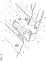
figure 3 is an enlarged perspective view of a portion offigure 2 in a second operating step. -
Figures 1A and 1B show a front portion of aheavy vehicle 1, for example a truck, comprising, as it is known, acabin 2 and provided with afront bumper 3. - The
front bumper 3 comprises atiltable footboard system 4, which is configured to assume a first closed position, in which it is integrated in thefront bumper 3, and a second open position, in which it defines a step designed to support the weight of an operator of the vehicle. - In particular, the
tiltable footboard system 4 comprises a step 5 and a pair oflateral arms 6. The step 5 and thelateral arms 6 are preferably manufactured as one single piece and made of steel. - More in detail, the
arms 6 each comprise anouter end 6a, which is connected to the step 5, and aninner end 6b, which is carried by the frame of the vehicle, namely by thebumper 2, in a movable manner. In particular, the step 5 has a substantially rectangular cross section and is laterally connected to the respectivefirst ends 6a of thearms 6 by means of a joining portion. - The
arms 6 preferably have a substantially rectangular cross section and extend parallel to one another and perpendicularly to the longitudinal extension of the step 5. As a consequence, thefootboard 4 substantially is, in plan view, "C"-shaped. - With reference to
figures 1B ,2 and3 , theinner end portion 6b of eacharm 6 comprises anengagement portion 7 defining a movable connection to thebumper 2, as described below. - In particular, the
engagement portion 7 defines, with thebumper 2, ahinge 9 and astop 10. Thehinge 9 and thestop 10 are advantageously both defined between theengagement portion 7 andbracket 11 carried by thebumper 2. - With reference to
figure 3 , in particular, thebracket 11 advantageously is "omega"-shaped and, hence, comprises a pair ofanchoring walls 11a, a pair of lateral walls 22b, each extending perpendicularly from an inner lateral edge of therespective anchoring wall 11a, and anupper wall 11a joining thelateral walls 11b to one another. - The anchoring
walls 11a can conveniently be fixed to an element that is fixed relative to thebumper 2 of thevehicle 1, for example by means of threaded means. Eachwall - The
bracket 11 further comprises a projectingportion 12 extending towards the inside of thevehicle 1 relative to aninner edge 2a of thebumper 2. Said projectingportion 12 comprises a pair oflateral walls 12a, which are advantageously manufactured in a continuous manner, hence in one single piece, with thelateral walls 11a of thebracket 11. - The projecting
portion 12 further comprises atransverse wall 12b connecting thelateral walls 12a to one another in a transverse direction. Saidlateral wall 12b advantageously is transverse to them and is preferably defined by the bending of two terminal portions of thelateral walls 12a onto themselves. - The
bracket 11 further comprises anopening 13 obtained on theupper wall 11c, preferably with a substantially rectangular shape. The opening 13 advantageously extends along at least the entire projecting extension of the projectingportion 12, i.e. the latter basically comprises, as mentioned above, thelateral walls 12a connected by thetransverse wall 12b. - The
bracket 11 further comprises apin 15, which is housed, in a fixed manner relative to thebracket 11, inside the latter and goes through two openings obtained in thelateral walls 11b. In particular, thepin 15 is carried by thebracket 11 in a longitudinal position such that, in a vertical direction, it is entirely under theopening 13. Thebracket 11 also comprises afurther pin 16, which is carried by thelateral walls 12a of the projectingportion 12 close to thetransverse wall 12b. In particular, saidpin 16 is housed in respective openings made in thelateral wall 12a and also is under the opening 13 in a vertical direction. - The
pin 16 advantageously is the pin of thehinge 9 obtained with theengagement portion 7. In particular, according to the defined geometry, thehinge 9 allows theinner end 6b of eacharm 6 to rotate around a transverse axis A, which is perpendicular to the longitudinal axis of thevehicle 1. - The
engagement portion 7 further comprises ahook 18, which is carried by theinner portion 6b and is configured to selectively cooperate in contact with thepin 15 in order to define thestop 10. According tofigures 2 and3 , thehook 18 basically comprises awall 19 extending perpendicularly from the upper surface of theinner end portion 6b towards thebumper 2. In particular, in the case described herein, thewall 19 extends from the middle line relative to the lateral edges of theinner end portion 6b. - In particular, the
wall 19 comprises a main portion 19a substantially having the shape of a circle sector, advantageously having an extension angle equal to an angle α, which can be pre-set and indicates the extension of the main portion between the segment having the minimum angular distance, namely in contact with the surface of theend portion 6b, and the segment having the maximum angular distance. In particular, said angle α that can be pre-set, in the case described herein, is 90°. - The
wall 19 further comprises astop portion 19b extending from the main portion 19a, in the area of the maximum height portion, namely at 90° relative to the surface of thearm 6. The dimensions of the main portion 19a and of thestop portion 19b are such that the main portion 19a never cooperates with thepin 15, whereas, after having reached the angle α, thestop portion 19b cooperates with the latter, preventing therelative arm 6 from rotating any further. - Furthermore, the
vehicle 1 also comprises selective coupling means (not shown), which are configured to allow thefootboard system 4 and thebumper 2 to be coupled in a selective and reversible manner. - For example, the selective coupling means can comprise a shape coupling between the
footboard system 4 and its seat in thebumper 2. - The embodiment of the
footboard system 4 for a heavy vehicle described above works as follows. - In the closed position (shown in
figures 1A and2 ), thefootboard system 4 is integrated in thebumper 2 and is held in this position thanks to the selective coupling means. In this configuration, thehook 18, i.e. thestop portion 19b of thewall 19, is at the maximum distance from thepin 15. - When, on the other hand, the
footboard system 4 is in the open position, thestop portion 19b is in contact with thepin 15 and, hence, keeps thearms 6 still, thus avoiding a further rotation due to the weight of thefootboard 4 itself. In this configuration, thearms 6 are inclined relative to thebumper 2 and the step 5 is spaced apart from the latter in order to allow an operator to step onto it. - When the operator wants to shift from the closed position to the open position of the
footboard 4, a force simply needs to be applied to the step 5 towards the ground, so that the selective coupling means allow thearms 6 to move around the axis of thehinge 9. The lowering movement continues as long as the rotation of thehook 18 establishes a contact between thestop portion 19b and thepin 15. - On the contrary, when the operator wants to shift from the open position to the closed position, a force simply needs to be applied to the step 5 towards the
bumper 2. There are no impediments to the movement of thehook 18 and of thearms 6 and, therefore, thefootboard system 4 goes back to the rest position in thebumper 2 and is kept there by the selective coupling means. - Owing to the above, the advantages of a
footboard system 4 for a heavy vehicle according to the invention are evident. - The fact that the
footboard system 4 comprises anengagement portion 7 defining, at the same time, the rotation by means of ahinge 9 and the maximum opening of the footboard by means of astop 10 allows for a safe opening of thefootboard 4 in a compact manner. - Furthermore, the special elements used as support, namely the
bracket 11 and the projectingportion 12, as well as thehook 18 cooperating with them, leads to a stable, compact, safe and versatile system for the opening of thefootboard 4. - Indeed, it is sufficient to change the shape of the
hook 18 in order to provide a plurality of maximum rotation angles of the step 5, maintaining thesame support elements - Moreover, given the absence of belts or other external support elements, there is not the usual impediment due to their presence.
- Finally, the
footboard system 4 for a heavy vehicle according to the invention can be subjected to changes and variants, which, though, do not go beyond the scope of protection set forth in the appended claims. - As already mentioned above, the supports given by the
brackets pins hook 18 or of thearms 6 can be changed based on the needs and on the type of vehicle.
Claims (7)
- A heavy vehicle comprising a bumper (2) and a tiltable footboard system (4) for said bumper (2), said footboard system (4) comprising a step (5) and at least an arm (6) connecting said step (5) and a support (11,12) fixed with respect to said bumper (2), said at least one arm (6) being configured to bring said step (5) from a first condition wherein it defines a step and a second position wherein it is integrated in said bumper (2), said footboard system (4) comprising an engagement portion (7) defining with said support (11,12) a hinge (9) configured to allow the passage of said step (5) between said first and second position and a stop (10) configured to maintain said step (5) in said second position, wherein said arm (6) comprises an outer portion (6a) connected to said step (5) and an inner portion (6b) comprising said engagement portion (7),
characterized in that said engagement portion (7) comprises a hook (18) comprising a wall (19) extending from said inner end portion (6b) and having a shape such as to permit the rotation of said hinge (9) within a pre-set maximum angle (α), said angle (α) representing the maximum angular extension of said wall (19) with respect to a surface of said inner end portion (6b). - The system according to claim 1, wherein said support (11,12) comprises an omega-shaped bracket (11) and a projecting portion (12) extending from said bracket (11), said support (11,12) further comprising an opening (13) provided in said projecting portion (12) and at least part of said bracket (11), said engagement portion (7) being at least partially housed in said opening.
- The system according to claim 2, wherein said bracket (11) comprises a pin (15) defining with said engagement portion (7) said stop (10) and wherein said projecting portion (12) comprises a respective pin (16) defining a rotation axis of said hinge (9).
- The system according to any of the preceding claims, wherein said angle (α) is smaller than 180°.
- The system according to any of the preceding claims, wherein said angle (α) is smaller than or equal to 90°.
- The system according to one of the preceding claims, wherein said wall (19) comprises a main portion (19a) having a shape such as not to cooperate in contact with said support (11, 12) in any operating condition of said wall (5).
- The system according to one of the preceding claims, wherein said wall (19) comprises a stop portion (19b) having a shape such as to cooperate in contact with said support (11, 12) when the rotation of said hinge (9) reaches said angle (α).
Applications Claiming Priority (3)
| Application Number | Priority Date | Filing Date | Title |
|---|---|---|---|
| IT102019000017009A IT201900017009A1 (en) | 2019-09-23 | 2019-09-23 | IMPROVED TIPPING PLATFORM SYSTEM FOR HEAVY VEHICLE |
| PCT/IB2020/058890 WO2021059159A1 (en) | 2019-09-23 | 2020-09-23 | Improved tiltable footboard system for heavy vehicle |
| EP20793144.5A EP4034425B1 (en) | 2019-09-23 | 2020-09-23 | Improved tiltable footboard system for heavy vehicle |
Related Parent Applications (2)
| Application Number | Title | Priority Date | Filing Date |
|---|---|---|---|
| EP20793144.5A Division-Into EP4034425B1 (en) | 2019-09-23 | 2020-09-23 | Improved tiltable footboard system for heavy vehicle |
| EP20793144.5A Division EP4034425B1 (en) | 2019-09-23 | 2020-09-23 | Improved tiltable footboard system for heavy vehicle |
Publications (2)
| Publication Number | Publication Date |
|---|---|
| EP4467398A2 true EP4467398A2 (en) | 2024-11-27 |
| EP4467398A3 EP4467398A3 (en) | 2025-03-12 |
Family
ID=69469019
Family Applications (2)
| Application Number | Title | Priority Date | Filing Date |
|---|---|---|---|
| EP20793144.5A Active EP4034425B1 (en) | 2019-09-23 | 2020-09-23 | Improved tiltable footboard system for heavy vehicle |
| EP24206055.6A Pending EP4467398A3 (en) | 2019-09-23 | 2020-09-23 | Improved tiltable footboard system for heavy vehicle |
Family Applications Before (1)
| Application Number | Title | Priority Date | Filing Date |
|---|---|---|---|
| EP20793144.5A Active EP4034425B1 (en) | 2019-09-23 | 2020-09-23 | Improved tiltable footboard system for heavy vehicle |
Country Status (4)
| Country | Link |
|---|---|
| EP (2) | EP4034425B1 (en) |
| KR (1) | KR102836111B1 (en) |
| IT (1) | IT201900017009A1 (en) |
| WO (1) | WO2021059159A1 (en) |
Citations (8)
| Publication number | Priority date | Publication date | Assignee | Title |
|---|---|---|---|---|
| US3517942A (en) | 1968-08-01 | 1970-06-30 | Moses L Cuffe | Hide-away step-up device |
| IT1107039B (en) | 1977-02-11 | 1985-11-18 | Kaessbohrer Fahrzeug Karl | INTEGRAL BUMPER VEHICLE WITH A DOOR |
| EP0885776A1 (en) | 1997-06-19 | 1998-12-23 | Volvo Lastvagnar Ab | Footstep bumper |
| US20030094781A1 (en) | 2001-10-26 | 2003-05-22 | Alfonso Jaramillo | Retractable step for vehicles and other purposes |
| CN200973932Y (en) | 2006-11-28 | 2007-11-14 | 张建明 | Footplate hinge joint mechanism for fire engine |
| JP2008260478A (en) | 2007-04-13 | 2008-10-30 | Hino Motors Ltd | Rotating support structure of movable step for vehicle |
| CN102407818A (en) | 2010-09-21 | 2012-04-11 | 陈言平 | Turnover auxiliary mask structure |
| US20130154229A1 (en) | 2011-12-14 | 2013-06-20 | Hyundai Motor Company | Bumper step for heavy-duty truck |
-
2019
- 2019-09-23 IT IT102019000017009A patent/IT201900017009A1/en unknown
-
2020
- 2020-09-23 EP EP20793144.5A patent/EP4034425B1/en active Active
- 2020-09-23 EP EP24206055.6A patent/EP4467398A3/en active Pending
- 2020-09-23 KR KR1020227013295A patent/KR102836111B1/en active Active
- 2020-09-23 WO PCT/IB2020/058890 patent/WO2021059159A1/en not_active Ceased
Patent Citations (8)
| Publication number | Priority date | Publication date | Assignee | Title |
|---|---|---|---|---|
| US3517942A (en) | 1968-08-01 | 1970-06-30 | Moses L Cuffe | Hide-away step-up device |
| IT1107039B (en) | 1977-02-11 | 1985-11-18 | Kaessbohrer Fahrzeug Karl | INTEGRAL BUMPER VEHICLE WITH A DOOR |
| EP0885776A1 (en) | 1997-06-19 | 1998-12-23 | Volvo Lastvagnar Ab | Footstep bumper |
| US20030094781A1 (en) | 2001-10-26 | 2003-05-22 | Alfonso Jaramillo | Retractable step for vehicles and other purposes |
| CN200973932Y (en) | 2006-11-28 | 2007-11-14 | 张建明 | Footplate hinge joint mechanism for fire engine |
| JP2008260478A (en) | 2007-04-13 | 2008-10-30 | Hino Motors Ltd | Rotating support structure of movable step for vehicle |
| CN102407818A (en) | 2010-09-21 | 2012-04-11 | 陈言平 | Turnover auxiliary mask structure |
| US20130154229A1 (en) | 2011-12-14 | 2013-06-20 | Hyundai Motor Company | Bumper step for heavy-duty truck |
Also Published As
| Publication number | Publication date |
|---|---|
| EP4034425A1 (en) | 2022-08-03 |
| EP4034425B1 (en) | 2025-03-26 |
| BR112022005362A2 (en) | 2022-06-14 |
| KR20220066359A (en) | 2022-05-24 |
| EP4034425C0 (en) | 2025-03-26 |
| IT201900017009A1 (en) | 2021-03-23 |
| EP4467398A3 (en) | 2025-03-12 |
| WO2021059159A1 (en) | 2021-04-01 |
| KR102836111B1 (en) | 2025-07-21 |
Similar Documents
| Publication | Publication Date | Title |
|---|---|---|
| EP2977273B1 (en) | A hinge arrangement for a bonnet and a bonnet arrangement | |
| EP1967675B1 (en) | Striker apparatus for vehicle | |
| US20150291072A1 (en) | Vehicle seat | |
| EP4165272A2 (en) | Drive assembly for driving a vehicle flap | |
| CN101513827B (en) | Opening/closing apparatus for swinging type sliding door | |
| EP4034425B1 (en) | Improved tiltable footboard system for heavy vehicle | |
| SI9300391A (en) | Louvre-type roller shutter | |
| EP4034426B1 (en) | Improved tiltable footboard system for heavy vehicle | |
| KR101908840B1 (en) | Apparatus for covering load box in truck | |
| EP3868582B1 (en) | Insulation unit and corresponding method | |
| US20250290325A1 (en) | Box enclosure hoist assembly, box enclosure and method for changing hoist assembly spring end attachment position | |
| US9181680B2 (en) | Motor grader | |
| EP3184377B1 (en) | Hinge arrangement | |
| JP6880476B2 (en) | Vehicle hinge structure | |
| US6019417A (en) | Articulated device for attaching a top storage well cover | |
| EP3625068B1 (en) | A suspension system of a vehicle axle | |
| US20080192369A1 (en) | Outside Rear View Mirror for Vehicles, Preferably for Motor Vehicles | |
| CN114150957A (en) | hood hinge structure | |
| EP3184375B1 (en) | Hinge arrangement | |
| EP1714828B1 (en) | Tipping body structure for goods transportation vehicles | |
| US9562381B2 (en) | Vehicle window assembly | |
| JP4997914B2 (en) | Door structure | |
| BR112022005362B1 (en) | Enhanced tilting step system for heavy vehicles. | |
| EP4470846B1 (en) | Underride guard for vehicles | |
| US9557145B2 (en) | Vehicle equipped with a door protection device ensuring an optimization of the opening clearance |
Legal Events
| Date | Code | Title | Description |
|---|---|---|---|
| PUAI | Public reference made under article 153(3) epc to a published international application that has entered the european phase |
Free format text: ORIGINAL CODE: 0009012 |
|
| STAA | Information on the status of an ep patent application or granted ep patent |
Free format text: STATUS: REQUEST FOR EXAMINATION WAS MADE |
|
| 17P | Request for examination filed |
Effective date: 20241011 |
|
| AC | Divisional application: reference to earlier application |
Ref document number: 4034425 Country of ref document: EP Kind code of ref document: P |
|
| AK | Designated contracting states |
Kind code of ref document: A2 Designated state(s): AL AT BE BG CH CY CZ DE DK EE ES FI FR GB GR HR HU IE IS IT LI LT LU LV MC MK MT NL NO PL PT RO RS SE SI SK SM TR |
|
| REG | Reference to a national code |
Ref country code: DE Ref legal event code: R079 Free format text: PREVIOUS MAIN CLASS: B60R0019480000 Ipc: B60R0003020000 |
|
| PUAL | Search report despatched |
Free format text: ORIGINAL CODE: 0009013 |
|
| AK | Designated contracting states |
Kind code of ref document: A3 Designated state(s): AL AT BE BG CH CY CZ DE DK EE ES FI FR GB GR HR HU IE IS IT LI LT LU LV MC MK MT NL NO PL PT RO RS SE SI SK SM TR |
|
| RIC1 | Information provided on ipc code assigned before grant |
Ipc: B60R 19/48 20060101ALI20250203BHEP Ipc: B60R 3/02 20060101AFI20250203BHEP |
|
| GRAP | Despatch of communication of intention to grant a patent |
Free format text: ORIGINAL CODE: EPIDOSNIGR1 |
|
| STAA | Information on the status of an ep patent application or granted ep patent |
Free format text: STATUS: GRANT OF PATENT IS INTENDED |
|
| INTG | Intention to grant announced |
Effective date: 20260219 |