EP4467382A1 - Electric vehicle control method and electric vehicle control device - Google Patents
Electric vehicle control method and electric vehicle control device Download PDFInfo
- Publication number
- EP4467382A1 EP4467382A1 EP22921008.3A EP22921008A EP4467382A1 EP 4467382 A1 EP4467382 A1 EP 4467382A1 EP 22921008 A EP22921008 A EP 22921008A EP 4467382 A1 EP4467382 A1 EP 4467382A1
- Authority
- EP
- European Patent Office
- Prior art keywords
- driving force
- dead zone
- electric vehicle
- command value
- torque command
- Prior art date
- Legal status (The legal status is an assumption and is not a legal conclusion. Google has not performed a legal analysis and makes no representation as to the accuracy of the status listed.)
- Withdrawn
Links
- 238000000034 method Methods 0.000 title claims abstract description 35
- 238000012545 processing Methods 0.000 claims abstract description 49
- 238000013016 damping Methods 0.000 claims abstract description 36
- 230000005540 biological transmission Effects 0.000 claims abstract description 31
- 238000012937 correction Methods 0.000 claims abstract description 31
- 230000007423 decrease Effects 0.000 claims description 4
- 230000004044 response Effects 0.000 description 39
- 238000010586 diagram Methods 0.000 description 27
- 238000012986 modification Methods 0.000 description 8
- 230000004048 modification Effects 0.000 description 8
- 230000001133 acceleration Effects 0.000 description 6
- 230000008859 change Effects 0.000 description 6
- 230000001172 regenerating effect Effects 0.000 description 5
- 238000001514 detection method Methods 0.000 description 4
- 230000009467 reduction Effects 0.000 description 3
- 238000006243 chemical reaction Methods 0.000 description 2
- 238000004891 communication Methods 0.000 description 2
- 239000000470 constituent Substances 0.000 description 2
- 230000000694 effects Effects 0.000 description 2
- 206010011878 Deafness Diseases 0.000 description 1
- 238000013459 approach Methods 0.000 description 1
- 238000007599 discharging Methods 0.000 description 1
- 230000007246 mechanism Effects 0.000 description 1
- 239000004065 semiconductor Substances 0.000 description 1
- 230000035939 shock Effects 0.000 description 1
- 238000012546 transfer Methods 0.000 description 1
Images







Classifications
-
- B—PERFORMING OPERATIONS; TRANSPORTING
- B60—VEHICLES IN GENERAL
- B60L—PROPULSION OF ELECTRICALLY-PROPELLED VEHICLES; SUPPLYING ELECTRIC POWER FOR AUXILIARY EQUIPMENT OF ELECTRICALLY-PROPELLED VEHICLES; ELECTRODYNAMIC BRAKE SYSTEMS FOR VEHICLES IN GENERAL; MAGNETIC SUSPENSION OR LEVITATION FOR VEHICLES; MONITORING OPERATING VARIABLES OF ELECTRICALLY-PROPELLED VEHICLES; ELECTRIC SAFETY DEVICES FOR ELECTRICALLY-PROPELLED VEHICLES
- B60L15/00—Methods, circuits, or devices for controlling the traction-motor speed of electrically-propelled vehicles
- B60L15/20—Methods, circuits, or devices for controlling the traction-motor speed of electrically-propelled vehicles for control of the vehicle or its driving motor to achieve a desired performance, e.g. speed, torque, programmed variation of speed
-
- B—PERFORMING OPERATIONS; TRANSPORTING
- B60—VEHICLES IN GENERAL
- B60L—PROPULSION OF ELECTRICALLY-PROPELLED VEHICLES; SUPPLYING ELECTRIC POWER FOR AUXILIARY EQUIPMENT OF ELECTRICALLY-PROPELLED VEHICLES; ELECTRODYNAMIC BRAKE SYSTEMS FOR VEHICLES IN GENERAL; MAGNETIC SUSPENSION OR LEVITATION FOR VEHICLES; MONITORING OPERATING VARIABLES OF ELECTRICALLY-PROPELLED VEHICLES; ELECTRIC SAFETY DEVICES FOR ELECTRICALLY-PROPELLED VEHICLES
- B60L50/00—Electric propulsion with power supplied within the vehicle
- B60L50/50—Electric propulsion with power supplied within the vehicle using propulsion power supplied by batteries or fuel cells
- B60L50/60—Electric propulsion with power supplied within the vehicle using propulsion power supplied by batteries or fuel cells using power supplied by batteries
-
- B—PERFORMING OPERATIONS; TRANSPORTING
- B60—VEHICLES IN GENERAL
- B60K—ARRANGEMENT OR MOUNTING OF PROPULSION UNITS OR OF TRANSMISSIONS IN VEHICLES; ARRANGEMENT OR MOUNTING OF PLURAL DIVERSE PRIME-MOVERS IN VEHICLES; AUXILIARY DRIVES FOR VEHICLES; INSTRUMENTATION OR DASHBOARDS FOR VEHICLES; ARRANGEMENTS IN CONNECTION WITH COOLING, AIR INTAKE, GAS EXHAUST OR FUEL SUPPLY OF PROPULSION UNITS IN VEHICLES
- B60K1/00—Arrangement or mounting of electrical propulsion units
- B60K1/02—Arrangement or mounting of electrical propulsion units comprising more than one electric motor
-
- B—PERFORMING OPERATIONS; TRANSPORTING
- B60—VEHICLES IN GENERAL
- B60L—PROPULSION OF ELECTRICALLY-PROPELLED VEHICLES; SUPPLYING ELECTRIC POWER FOR AUXILIARY EQUIPMENT OF ELECTRICALLY-PROPELLED VEHICLES; ELECTRODYNAMIC BRAKE SYSTEMS FOR VEHICLES IN GENERAL; MAGNETIC SUSPENSION OR LEVITATION FOR VEHICLES; MONITORING OPERATING VARIABLES OF ELECTRICALLY-PROPELLED VEHICLES; ELECTRIC SAFETY DEVICES FOR ELECTRICALLY-PROPELLED VEHICLES
- B60L2220/00—Electrical machine types; Structures or applications thereof
- B60L2220/40—Electrical machine applications
- B60L2220/42—Electrical machine applications with use of more than one motor
-
- B—PERFORMING OPERATIONS; TRANSPORTING
- B60—VEHICLES IN GENERAL
- B60L—PROPULSION OF ELECTRICALLY-PROPELLED VEHICLES; SUPPLYING ELECTRIC POWER FOR AUXILIARY EQUIPMENT OF ELECTRICALLY-PROPELLED VEHICLES; ELECTRODYNAMIC BRAKE SYSTEMS FOR VEHICLES IN GENERAL; MAGNETIC SUSPENSION OR LEVITATION FOR VEHICLES; MONITORING OPERATING VARIABLES OF ELECTRICALLY-PROPELLED VEHICLES; ELECTRIC SAFETY DEVICES FOR ELECTRICALLY-PROPELLED VEHICLES
- B60L2240/00—Control parameters of input or output; Target parameters
- B60L2240/40—Drive Train control parameters
- B60L2240/42—Drive Train control parameters related to electric machines
- B60L2240/423—Torque
-
- B—PERFORMING OPERATIONS; TRANSPORTING
- B60—VEHICLES IN GENERAL
- B60L—PROPULSION OF ELECTRICALLY-PROPELLED VEHICLES; SUPPLYING ELECTRIC POWER FOR AUXILIARY EQUIPMENT OF ELECTRICALLY-PROPELLED VEHICLES; ELECTRODYNAMIC BRAKE SYSTEMS FOR VEHICLES IN GENERAL; MAGNETIC SUSPENSION OR LEVITATION FOR VEHICLES; MONITORING OPERATING VARIABLES OF ELECTRICALLY-PROPELLED VEHICLES; ELECTRIC SAFETY DEVICES FOR ELECTRICALLY-PROPELLED VEHICLES
- B60L2240/00—Control parameters of input or output; Target parameters
- B60L2240/40—Drive Train control parameters
- B60L2240/46—Drive Train control parameters related to wheels
- B60L2240/463—Torque
-
- B—PERFORMING OPERATIONS; TRANSPORTING
- B60—VEHICLES IN GENERAL
- B60L—PROPULSION OF ELECTRICALLY-PROPELLED VEHICLES; SUPPLYING ELECTRIC POWER FOR AUXILIARY EQUIPMENT OF ELECTRICALLY-PROPELLED VEHICLES; ELECTRODYNAMIC BRAKE SYSTEMS FOR VEHICLES IN GENERAL; MAGNETIC SUSPENSION OR LEVITATION FOR VEHICLES; MONITORING OPERATING VARIABLES OF ELECTRICALLY-PROPELLED VEHICLES; ELECTRIC SAFETY DEVICES FOR ELECTRICALLY-PROPELLED VEHICLES
- B60L2270/00—Problem solutions or means not otherwise provided for
- B60L2270/10—Emission reduction
- B60L2270/14—Emission reduction of noise
- B60L2270/145—Structure borne vibrations
-
- Y—GENERAL TAGGING OF NEW TECHNOLOGICAL DEVELOPMENTS; GENERAL TAGGING OF CROSS-SECTIONAL TECHNOLOGIES SPANNING OVER SEVERAL SECTIONS OF THE IPC; TECHNICAL SUBJECTS COVERED BY FORMER USPC CROSS-REFERENCE ART COLLECTIONS [XRACs] AND DIGESTS
- Y02—TECHNOLOGIES OR APPLICATIONS FOR MITIGATION OR ADAPTATION AGAINST CLIMATE CHANGE
- Y02T—CLIMATE CHANGE MITIGATION TECHNOLOGIES RELATED TO TRANSPORTATION
- Y02T10/00—Road transport of goods or passengers
- Y02T10/60—Other road transportation technologies with climate change mitigation effect
- Y02T10/72—Electric energy management in electromobility
Definitions
- the present invention relates to an electric vehicle control method and an electric vehicle control device.
- WO2017/ 183231A1 discloses a control method for reducing vibration of a driving force transmission system in an electric vehicle that can be driven using torque from an electric motor, in consideration of transmission characteristics of a power transmission mechanism connected between an output shaft of a drive motor and driving wheels. Especially, in this control method, a dead zone section in which the drive motor torque is not transmitted to drive shaft torque of the electric vehicle is estimated, and processing of accelerating response of the drive shaft torque is performed in the dead zone section, thereby preventing shock due to influence of gear backlash.
- inventors of the present invention have focused on the point that, in the case of an electric vehicle that includes a plurality of drive systems that are individually provided with drive motors and drive different driving wheels, the timing at which the backlash of the gear is clogged differs for each drive system due to a difference in driving force distribution between the drive systems, and a length of the dead zone section may vary. For this reason, even when the electric vehicle control method in the related art is applied to the electric vehicle including the plurality of drive systems, torque response performance of the electric vehicle in the dead zone section may be changed depending on a traveling state, and an occupant may feel uncomfortable.
- an object of the present invention is to provide an electric vehicle control method and an electric vehicle control device capable of reducing a sense of discomfort of an occupant caused by a variation in length of a dead zone section of each drive system in an electric vehicle including a plurality of drive motors.
- the electric vehicle control method includes: basic torque distribution processing of determining a basic torque command value for each drive motor based on a total required driving force for the electric vehicle and driving force distribution for each of the drive systems; vibration damping processing of obtaining a corrected torque command value by performing correction for reducing vibration of a driving force transmission system on each basic torque command value; and driving force control processing of controlling a driving force generated by each drive motor based on the corrected torque command value.
- the vibration damping processing includes estimating whether each of the drive systems is in a dead zone section individually, and adjusting a correction amount for the basic torque command value of the drive system in the dead zone section according to the driving force distribution.
- FIG. 1 is a block diagram illustrating a main configuration of an electric vehicle 100 in which an electric vehicle control method is executed.
- the electric vehicle 100 in the present embodiment means a vehicle such as an electric vehicle (EV) or a hybrid electric vehicle (HEV) equipped with one or a plurality of electric motors (drive motors 4) as a traveling drive source.
- the electric vehicle 100 of the present embodiment includes a front drive system S ⁇ including the drive motor 4 (front drive motor 4f) that provides a driving force to front driving wheels 9fR and 9fL, and a rear drive system S r including the drive motor 4 (rear drive motor 4r) that provides a driving force to rear driving wheels 9rR and 9rL.
- a battery 1 is an in-vehicle secondary battery capable of supplying drive power (discharging) during power running operation of the drive motor 4f, 4r and receiving regenerative power (charging) during regenerative operation.
- An electric motor controller 2 receives signals indicating various vehicle variables such as a vehicle speed V, an accelerator opening APO, a rotor phase ⁇ f , ⁇ r of the drive motor 4f, 4r, and a motor current i f , i r , which is a current flowing through the drive motor 4 f , 4 r , as digital signals.
- the electric motor controller 2 generates a PWM signal for controlling the drive motor 4f, 4r based on the input signals.
- the electric motor controller 2 also generates a drive signal for an inverter 3f, 3r according to the generated PWM signal.
- the inverter 3f, 3r converts a direct current supplied from the battery 1 into an alternating current by turning on and off two switching elements (for example, power semiconductor elements such as IGBTs and MOS-FETs) provided for each phase, and flows a desired current to the drive motor 4f, 4r.
- switching elements for example, power semiconductor elements such as IGBTs and MOS-FETs
- the drive motor 4f, 4r generates a driving force by the alternating current supplied from the inverter 3f, 3r, and transmits the driving force to the driving wheel 9fR, 9fL, 9rR, 9rL via a driving force transmission system including a reduction gear 5f, 5r and a drive shaft Dsf, Dsr.
- the drive motor 4f, 4r recovers kinetic energy based on a regenerative braking force received from the driving wheel 9fR, 9fL, 9rR, 9rL as electric energy when the vehicle is traveling.
- the inverter 3 converts the alternating current generated during regenerative operation of the drive motor 4 into a direct current and supplies the direct current to the battery 1.
- the front drive motor 4f supplies a driving force to the front driving wheels 9fR and 9fL
- the rear drive motor 4r supplies a driving force to the rear driving wheels 9rR and 9rL.
- a current sensor 20 detects a motor current i f , i r (particularly, front three-phase alternating currents i uf and i vf and i wf and rear three-phase alternating currents i ur and i vr and i wr ). However, since the sum of the three-phase alternating currents i u , i v , and i w is 0, the currents of any two phases may be detected, and the current of the remaining one phase may be calculated.
- a rotation sensor 21 is, for example, a resolver or an encoder, and detects the rotor phase ⁇ f , ⁇ r of the drive motor 4f, 4r.
- FIG. 2 is a flowchart showing each processing in the electric vehicle control method programmed to be executed by the electric motor controller 2. Note that the processing according to steps S201 to S205 shown in FIG. 2 is repeatedly executed at a predetermined calculation cycle while a vehicle system is activated.
- the electric motor controller 2 executes input processing. Specifically, the electric motor controller 2 receives the signals indicating various vehicle states as vehicle information. Specifically, the signals indicating the vehicle states include the vehicle speed V (km/h), the accelerator opening APO (%), the rotor phase ⁇ f , ⁇ r (rad), a motor rotation speed N mf , N mr (rpm), which is a rotation speed of the drive motor 4f, 4r, the motor current i f , i r , and a DC voltage value V dc (V) of the battery 1.
- the vehicle speed V (km/h) is obtained from a meter or other controllers such as a brake controller through communication.
- the electric motor controller 2 may calculate a vehicle speed v (m/s) by multiplying a mechanical angular velocity ⁇ m of the drive motor 4 (for example, either one of a front mechanical angular velocity ⁇ mf and a rear mechanical angular velocity ⁇ mr ) by a tire dynamic radius r, and then dividing the product by a gear ratio of a final gear, and may obtain the vehicle speed V (km/h) by performing unit conversion by multiplying the vehicle speed v (m/s) by 3600/1000.
- the accelerator opening APO (%) is obtained from an accelerator opening sensor (not shown) or from other controllers such as a vehicle controller (not shown) through communication.
- the rotor phase ⁇ f , ⁇ r (rad) is obtained from a rotation sensor 21.
- the electric motor controller 2 differentiates the rotor phase ⁇ f , a r to calculate a rotor angular velocity ⁇ ef , ⁇ er (electric angular velocity) of the drive motor 4f, 4r.
- the electric motor controller 2 calculates a motor rotation angular velocity ⁇ mf , ⁇ mr (rad/s), which is the mechanical angular velocity of the drive motor 4f, 4r, by dividing the rotor angular velocity ⁇ ef , ⁇ er by the number p of pole pairs of the drive motor 4f, 4r.
- the electric motor controller 2 calculates a motor rotation speed N mf , N mr (rpm) by multiplying the motor rotation angular velocity ⁇ mf , ⁇ mr by a unit conversion coefficient (60/2 ⁇ ).
- the motor current i f , i r (A) is obtained from the current sensor 20.
- the DC voltage value V dc (V) is detected by a voltage sensor (not shown) provided in a DC power supply line between the battery 1 and the inverter 3. Note that a power supply voltage value obtained by a battery controller (not shown) may be obtained as the DC voltage value V dc (V).
- step S202 the electric motor controller 2 executes basic torque distribution processing. Specifically, the electric motor controller 2 sets a basic total torque command value T m * which is a target value of a total required driving force for the electric vehicle 100 by referring to an accelerator opening-torque table shown in FIG. 3 based on the accelerator opening APO, the vehicle speed V, and the motor rotation speed N m .
- the electric motor controller 2 executes front-rear torque distribution processing shown in FIG. 4 . Specifically, the electric motor controller 2 multiplies the basic total torque command value T m * by a front distribution gain Kf (0 ⁇ Kf ⁇ 1) to obtain a front basic torque command value T mf * corresponding to a target value of the driving force distributed to the front drive system Sf. The electric motor controller 2 multiplies the basic total torque command value T m * by a rear distribution gain (1 - K f ) to obtain a rear basic torque command value T mr * corresponding to a target value of the driving force distributed to the rear drive system S r .
- step S203 the electric motor controller 2 executes vibration damping processing. Specifically, the electric motor controller 2 obtains a front final torque command value T mff * by performing correction on the front basic torque command value T mf * for reducing vibration of the driving force transmission system (such as torsional vibration of a front drive shaft Dsf). On the other hand, the electric motor controller 2 obtains a rear final torque command value T mrf * by performing vibration compensation calculation on the rear basic torque command value T mr * for reducing vibration of the driving force transmission system (such as torsional vibration of a rear drive shaft Dsr). Details of the vibration damping processing will be described later.
- step S204 the electric motor controller 2 executes current command value calculation processing.
- the electric motor controller 2 refers to a predetermined table to determine a d-axis current target value i df *, i dr * and a q-axis current target value i qf *, i qr * of the front drive motor 4f and the rear drive motor 4r respectively, based on the final torque command value T mff *, T mrf * obtained in step S203, the motor rotation angular velocity ⁇ mf , ⁇ mr *, and the DC voltage value V dc .
- step S205 the electric motor controller 2 executes current control calculation processing. Specifically, the electric motor controller 2 performs control for matching a d-axis current i df and a q-axis current i qf of the front drive motor 4f with the d-axis current target value i df * and the q-axis current target value i qf *, respectively, and for matching a d-axis current i dr and a q-axis current i qr of the rear drive motor 4r with the d-axis current target value i dr * and the q-axis current target value i qr *, respectively.
- the electric motor controller 2 generates a PWM signal based on the d-axis current target value i df *, i dr * and the q-axis current target value i qf *, i qr * of the drive motor 4f, 4r.
- the front drive motor 4f and the rear drive motor 4r can be driven with respective desired torques.
- FIG. 5 is a block diagram illustrating the vibration damping processing according to the present embodiment.
- the vibration damping processing S203 of the present embodiment includes a configuration (upper diagram of FIG. 5 ) for performing processing of reducing vibration of the driving force transmission system in the front drive system Sf and a configuration (lower diagram of FIG. 5 ) for performing processing of reducing vibration of the driving force transmission system in the rear drive system S r .
- a configuration upper diagram of FIG. 5
- FIG. 5 for performing processing of reducing vibration of the driving force transmission system in the rear drive system S r
- components of the front drive system Sf and the rear drive system S r are collectively described with reference numerals thereof together.
- the vibration damping processing S203 includes an F/F compensator S501, S503 and an F/B compensator S502, S504.
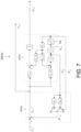
- FIGS. 6 and 7 are block diagrams illustrating the F/F compensator S501, S503.
- the F/F compensator S501, S503 includes a vehicle model S601, S701 and a torque correction unit S602, S702.
- the vehicle model S601, S701 receives a first torque command value T mf1 *, T mr1 * obtained by the torque correction unit S602, S702, and obtains a torsional angular velocity estimation value ⁇ df , ⁇ dr and a torsional angle estimation value ⁇ df , ⁇ dr of the drive shaft Dsf, Dsr using a dead zone model simulating driving force characteristics of the electric vehicle 100.
- the torsional angular velocity estimation value ⁇ df , ⁇ dr is fed back to the torque correction unit S602, S702, and functions as an index for determining a correction amount for reducing vibration in the torque correction unit S602, S702.
- the torsional angle estimation value ⁇ df , ⁇ dr is fed back to the torque correction unit S602, S702, and functions as an index for determining whether each of the drive systems Sf and S r is in a dead zone section.
- the dead zone section of the drive system S f , S r means a section in which an output torque (hereinafter, also referred to as “motor torque T mf , T mr ”) of the drive motor 4f, 4r is not transmitted to a torque (hereinafter, also referred to as “drive shaft torque T df , T dr ”) of the drive shaft Dsf, Dsr during a period such as when gear backlash is clogged.
- the dead zone section of the drive system S f , S r is individually defined for the front drive system S f and the rear drive system S r .
- a state in which both the drive systems S f and S r are in a dead zone section (a state in which there is no torque response of the electric vehicle 100) is appropriately referred to as a "dead zone section of the electric vehicle 100".
- the vehicle model S601, S701 obtains an estimation value of a motor rotation angular velocity ⁇ mf , ⁇ m (hereinafter, also referred to as "motor rotation angular velocity estimation value ⁇ mf , ⁇ mr ”) on the basis of the first torque command value T mf1 *, T mr1 *, and outputs the estimation value to the F/B compensator S502, S504.
- motor rotation angular velocity estimation value ⁇ mf , ⁇ mr hereinafter, also referred to as "motor rotation angular velocity estimation value ⁇ mf , ⁇ mr ”
- the torque correction unit S602, S702 receives the basic torque command value T mf *, T mr *, the torsional angle estimation value ⁇ df , ⁇ dr , and the torsional angular velocity estimation value ⁇ df , ⁇ dr , and calculates the first torque command value T mf1 *, T mr1 *.
- the torque correction unit S602, S702 obtains a vibration compensation torque ⁇ T mf , ⁇ T mr by multiplying the torsional angular velocity estimation value ⁇ df , ⁇ dr by a predetermined feedback gain, and calculates the first torque command value T mf1 *, T mr1 * by subtracting the vibration compensation torque ⁇ T mf , ⁇ T mr from the basic torque command value T mf *, T mr *.
- the torque correction unit S602, S702 calculates the vibration compensation torque ⁇ T mf , ⁇ T mr using a normal gain k f1 , k r1 or a dead zone gain k f2 , k r2 , which will be described later, as the feedback gain, in accordance with a reference result of the torsional angle estimation value ⁇ df , ⁇ dr input from the vehicle model S601, S701.
- the torque correction unit S602, S702 obtains the vibration compensation torque ⁇ T mf , ⁇ T mr by multiplying the torsional angular velocity estimation value ⁇ df , ⁇ dr by the normal gain k f1 , k r1 .
- the torque correction unit S602, S702 obtains the vibration compensation torque ⁇ T mf , ⁇ T mr by multiplying the torsional angular velocity estimation value ⁇ df , ⁇ dr by the dead zone gain k f2 , kr2.
- FIG. 8 is a diagram illustrating a model of the driving force transmission system of the electric vehicle 100. Note that definitions of parameters including those already described will be described below.
- equations of motion of the 4WD electric vehicle 100 are expressed by the following equations (1) to (11).
- [Math. 1] J mf ⁇ ⁇ ⁇ mf T mf ⁇ T df / N f
- J mr ⁇ ⁇ ⁇ mr T mr ⁇ T dr / N r
- J wf ⁇ ⁇ ⁇ wf T df ⁇ r f F f
- J wr ⁇ ⁇ wr T dr ⁇ r r F r [Math.
- v l , v 0 , w l , and w 0 are determined by the following equations in (23).
- Equation (15) can be transformed as the following equation (24).
- ⁇ p is an attenuation coefficient of the torque transmission system of the front drive shaft Dsf
- ⁇ p is a frequency of normal mode of vibration of the torque transmission system of the front drive shaft Dsf.
- gtf c 0 / a 3 ⁇ ⁇
- T mff * T mf * ⁇ k f 1 s T df / K df
- T df g tf s 2 + 2 ⁇ r ⁇ p s + ⁇ p 2 T fm *
- the normal gain k ⁇ i is determined from the viewpoint of achieving the model response in a normal section in which the front motor torque T mf is transmitted as the front drive shaft torque T df .
- ⁇ ⁇ f represents an attenuation coefficient of a model response in the dead zone section of the front drive system Sf (hereinafter also referred to as “front dead zone attenuation coefficient " ⁇ ⁇ f ").
- the front dead zone gain k f2 is determined from the viewpoint of achieving the model response in the dead zone section where the front motor torque T mf is not sufficiently transmitted as the front drive shaft torque T df .
- the front dead zone attenuation coefficient ⁇ ⁇ f is set to be smaller than the attenuation coefficient (" 1" in the present embodiment) in the model response of a normal section, according to the equations (31) and (32), the dead zone gain k f2 becomes smaller than the normal gain k f1 .
- the vibration compensation torque ⁇ T mf determined by the product of the front torsional angular velocity ⁇ df and the dead zone gain k f2 (that is, a reduction correction amount with respect to the front basic torque command value T mf *) becomes small, so that the torque response becomes faster than in the normal section.
- T df K df ⁇ df ⁇ ⁇ deadf / 2 0 K df ⁇ df + ⁇ deadf / 2 ⁇ df ⁇ ⁇ deadf / 2 ⁇ ⁇ deaf / 2 ⁇ ⁇ df ⁇ ⁇ deadf / 2 ⁇ df ⁇ ⁇ deadf / 2
- ⁇ deadf represents an overall gear backlash amount from the front drive motor 4f to the front drive shaft Dsf.
- the normal gain k r1 and the dead zone gain k r2 in the rear drive system S r can also be obtained according to the following equations (34) and (35) by calculation logic similar to that for obtaining the normal gain kfi and the dead zone gain k f2 in the front drive system Sf.
- k r 1 2 1 ⁇ ⁇ pr ⁇ pr K dr / g tr
- k r 2 2 ⁇ ⁇ r ⁇ ⁇ pr ⁇ pr K dr / g tr
- ⁇ ⁇ r represents an attenuation coefficient of a model response in the rear dead zone section (hereinafter, also referred to as “rear dead zone attenuation coefficient ⁇ ⁇ r ").
- T dr K dr ⁇ dr ⁇ ⁇ deadr / 2 0 K dr ⁇ dr + ⁇ deadr / 2 ⁇ dr ⁇ ⁇ deadr / 2 ⁇ ⁇ dear / 2 ⁇ ⁇ dr ⁇ ⁇ deadr / 2 ⁇ dr ⁇ ⁇ deadr / 2
- dead zone models of the front drive system Sf and the rear drive system S r shown in the above equations (33) and (36) are implemented by a dead zone block B df shown in FIG. 6 and a dead zone block B dr shown in FIG. 7 , respectively.
- the dead zone gains k f2 and k r2 that change according to the driving force distribution are determined. A more specific description will be given.
- FIG. 9 is a diagram illustrating the torque response characteristics of the electric vehicle 100 of the present embodiment.
- the change with time of each parameter when the front distribution gain Kf is set to 1 is indicated by a solid line
- the change with time of each parameter when the front distribution gain K f is set to 0 is indicated by a broken line.
- (A) of FIG. 9 shows the basic total torque command value T m *
- (B) of FIG. 9 shows the front final torque command value T mff *
- (C) of FIG. 9 shows the rear final torque command value T mrf *
- (D) of FIG. 9 shows a longitudinal acceleration G of the electric vehicle 100.
- FIG. 10 shows a driving force distribution ratio-dead zone attenuation coefficient table.
- FIG. 11 shows a relation between the front torque correction unit S602 and the driving force distribution ratio-dead zone attenuation coefficient table.
- the rear dead zone attenuation coefficient ⁇ ⁇ r in the rear drive system S r is maintained at the reference attenuation coefficient. Accordingly, it is possible to reduce the variation in the torque response characteristic caused by the change in the driving force distribution of the front drive system Sf and to further improve the torque response performance of the electric vehicle 100.
- the front dead zone attenuation coefficient ⁇ ⁇ f is maintained at the reference attenuation coefficient.
- the torque response characteristic of the electric vehicle 100 in the dead zone section can be made close to the characteristic in the case where only the front drive system Sf is used as the drive source, which shows the highest torque response characteristic.
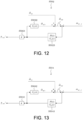
- FIGS. 12 and 13 are block diagrams showing configurations of the F/B compensators S502 and S504. Specially, FIG. 12 shows the configuration of the front F/B compensator S502, and FIG. 13 shows the configuration of the rear F/B compensator S504.
- the F/B compensator S502, S504 includes a gain unit S5021, S5041, a filter unit S5022, S5042, and a filter unit S5023, S5043.
- the gain K used in the gain unit S5021, S5041 is set to adjust stability margin (gain margin, phase margin) of a feedback control system, and is set to a value of 1 or less.
- the filter unit S5022, S5042 is a filter having a transmission characteristic Gp(s) that simulates the transmission characteristic from the motor torque T mf , T mr to the motor rotation angular velocity ⁇ mf , ⁇ mr .
- the transmission characteristic Gp(s) is determined by, for example, the above equation (13).
- the filter unit S5023, S5043 is a filter of H(s)/Gp(s) including an inverse system of the transmission characteristic Gp(s) and a band-pass filter H(s).
- the band-pass filter H (s) is set such that attenuation characteristics on a low-pass side and a high-pass side substantially coincide with each other, and a torsional resonance frequency f p of the drive system is in the vicinity of a central portion of a passband on a logarithmic axis (log scale).
- the frequency f p is a torsional resonance frequency of the drive systems S ⁇ and S r
- k is any value constituting the band pass.
- the F/B compensator S502, S504 adds the motor rotation angular velocity estimation value ⁇ mf , ⁇ mr based on the first torque command value T mf1 *, T mr1 * calculated by the vehicle model S601, S701 of the F/F compensator S501, S503 and the motor rotation angular velocity estimation value ⁇ mf1 , ⁇ mr1 calculated by inputting a second torque command value T mf2 *, T mr2 * before being multiplied by the gain K to the transmission characteristic Gp(s), to calculate a final motor rotation angular velocity estimated value ⁇ mff and ⁇ mrf .
- the F/B compensator S502, S504 calculates a deviation between the final motor rotation angular velocity estimated value ⁇ mff , ⁇ mrf and a motor rotation angular velocity detection value ⁇ mf_d , ⁇ mr_d obtained by the rotation sensor 21, and applies the filter H(s)/Gp(s) to the deviation and multiply the result by a gain K to obtain the second torque command value T mf2 *, T mr2 *.
- the final torque command value T mff *, T mrf * is calculated as the sum of the first torque command value T mf1 *, T mr1 * output from the F/F compensator S501, S503 and the second torque command value T mf2 *, T mr2 * output from the F/B compensator S502, S504.
- an electric vehicle control method for controlling the driving force of each of the drive systems S f and S r in the electric vehicle 100 equipped with the drive systems S f and S r including the drive motors 4f and 4r respectively.
- the electric vehicle control method includes: the basic torque distribution processing S202 of determining the basic torque command value T mf *, T mr * for each of the drive motors 4f and 4r based on the total required driving force (basic total torque command value T m *) for the electric vehicle 100 and driving force distribution (Kf or 1 - Kf) for each of the drive systems Sf and S r ; the vibration damping processing S203 of obtaining a corrected torque command value (first torque command value T mf1 *, T mr1 * or final torque command value T mff *, T mrf *) by performing correction for reducing vibration of the driving force transmission system on each basic torque command value T mf *, T mr *; and driving force control processing (S204, S205) of controlling the driving force (motor torque T mf , T mr ) generated by each of the drive motors 4f and 4r based on the corrected torque command value (more specifically, the final torque command value T mff *, T m
- the vibration damping processing S203 includes estimating whether each of the drive systems S f and S r is in a dead zone section individually, and adjusting a correction amount (vibration compensation torque ⁇ T mf , ⁇ T mr ) for the basic torque command value T mf *, T mr * of the drive system S f , S r in the dead zone section according to the driving force distribution (see FIG. 11 ).
- vibration compensation is performed on each basic torque command value T mf *, T mr *, taking into account the variation in the torque response characteristic in the dead zone section due to the difference in the driving force distribution, and the final torque command value T mff *, T mrf * can be determined. Accordingly, in the electric vehicle 100 equipped with the drive systems S f and S r , a control configuration in which the sense of discomfort of the occupant is reduced while maintaining the vibration damping function.
- the vibration compensation torque ⁇ T mf , ⁇ T mr is obtained by multiplying the torsional angular velocity estimation value ⁇ df , ⁇ dr of the drive shaft Dsf, Dsr in the drive system S f , S r by a predetermined feedback gain (k f1 , k f2 , k r1 , k r2 ), and the corrected torque command value (first torque command value T mf1 *, T mr1 * is obtained by subtracting the vibration compensation torque ⁇ T mf , ⁇ T mr from the basic torque command value T mf *, T mr * (torque correction unit S602, S702).
- the feedback gain in the normal section is set to the normal gain k f1 , k r1 that is constant with respect to the change in the driving force distribution, and the feedback gain in the dead zone section is set to the dead zone gain k f2 , k r2 corresponding to the driving force distribution.
- the dead zone gain k f2 , k r2 is determined so that a timing at which the drive system S f , S r passes through the dead zone section is substantially constant regardless of the driving force distribution.
- the torsional angular velocity estimation value ⁇ df , ⁇ dr of the drive shaft Dsf, Dsr of the drive system S f , S r is calculated using the vehicle model S601, S701 obtained by modeling the driving force transmission system of the electric vehicle 100.
- the vibration damping processing is applied to the electric vehicle 100 including the plurality of drive systems S f and S r , it is possible to determine the vibration compensation torques ⁇ T mf , ⁇ T mr for achieving the preferable vibration damping function in the drive systems Sf and S r by the feedforward calculation based on the torsional angular velocity estimation value ⁇ df , ⁇ dr determined from the model corresponding to the actual electric vehicle 100.
- the feedback vibration compensation torque (the second torque command value T mf2 *, T mr2 *) is determined by feedback control to match each torsional angular velocity estimation value ⁇ df , ⁇ dr based on the vehicle model S601, S701 with each motor rotation angular velocity detection value ⁇ mf_d , ⁇ mr_d , even in a configuration in which vibration damping processing is performed for the plurality of drive systems Sf and S r , excess vibration damping compensation can be appropriately removed from each torque command value (first torque command value T mf1 *, T mr1 *) after feedforward compensation in the F/F compensator S501, S503, thereby ensuring the accuracy of the vibration compensation.
- the torsional angle estimation value ⁇ df , ⁇ dr of the drive shaft Dsf, Dsr in the drive system S f , S r is further obtained using the vehicle model S601, S701.
- the dead zone gain k f2 , k r2 of the drive system S f , S r to which a relatively large driving force is distributed is made smaller than the normal gain k f1 , k r1 that is set when the drive system S f , S r is in a section other than the dead zone section.
- the stay time in the dead zone section of the drive system S f , S r to which a relatively large driving force is distributed is further shortened, and thus the torque response of the electric vehicle 100 can be further accelerated.
- the drive system S f , S r having a larger distributed driving force can quickly leave the dead zone section and output a driving force closer to the total required driving force of the electric vehicle 100. That is, in this scene, the same characteristics as in a case where the electric vehicle 100 is independently driven by the drive system S f , S r having a larger distributed driving force can be obtained.
- the dead zone gain k f2 , k r2 of the drive system S f , S r is set such that the dead zone gain k f2 of one of the drive systems (for example, the front drive system Sf) having a characteristic that the dead zone section is the shortest when all the driving force is distributed thereto is smaller than the normal gain k f1 that is set when the drive system S ⁇ is in a section other than the dead zone section.
- a torque response timing of the electric vehicle 100 in the dead zone section can be matched with a backlash crossing timing of the front drive system S ⁇ having a short dead zone section in terms of mechanical characteristics. That is, the torque response of the electric vehicle 100 can be further accelerated.
- an electric motor controller 2 that functions as an electric vehicle control device for executing the above-described electric vehicle control method.
- the electric motor controller 2 includes: a basic torque distribution unit (S202) for determining the basic torque command value T mf *, T mr * for each of the drive motors 4f and 4r based on the total required driving force (basic total torque command value T m *) for the electric vehicle 100 and driving force distribution (Kf or 1 - Kf) for each of the drive systems S f and S r ; the vibration damping unit (S203) for obtaining a corrected torque command value (first torque command value T mf1 *, T mr1 * or final torque command value T mff *, T mrf *) by performing correction for reducing vibration of the driving force transmission system on each basic torque command value T mf *, T mr *; and a driving force control unit (S204, S205) for controlling
- the vibration damping unit (S203) also estimates whether each of the drive systems Sf and S r is in a dead zone section individually, and adjusts a correction amount (vibration compensation torque ⁇ T mf , ⁇ T mr ) for the basic torque command value T mf *, T mr * of the drive system S f , S r in the dead zone section according to the driving force distribution (see FIG. 11 ).
- FIG. 14 is a block diagram illustrating the vibration damping processing S203 of the present embodiment. Especially, in the present embodiment, an F/F compensator S1201 is used instead of the F/F compensator S501, S503 of the first embodiment.
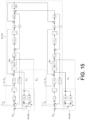
- FIG. 15 is a block diagram illustrating a configuration of the F/F compensator S1201.
- the F/F compensator S1201 includes a vehicle model S1301 including dead zone models simulating driving force characteristics of the front drive system Sf and the rear drive system S r , a front torque correction unit S1302 for obtaining the front first torque command value T mf1 * from the front basic torque command value T mf * and the front torsional angular velocity estimation value ⁇ df , and a rear torque correction unit S1303 for obtaining the rear first torque command value T mr1 * from the rear basic torque command value T mr * and the rear torsional angular velocity estimation value ⁇ dr .
- the normal gain k f1 and the dead zone gain k f2 in the front drive system Sf can be determined by the equations (31) and (32), respectively, as in the first embodiment.
- the normal gain k r1 and the dead zone gain k r2 in the rear drive system S r can be determined by the equations (34) and (35), respectively, as in the first embodiment.
- the backlash characteristic of the gear from the drive motor 4f, 4r to the drive shaft Dsf, Dsr in the drive system S f , S r can be determined from the equations (33) and (36), respectively, as in the first embodiment.
- the vibration damping processing S203 includes a F/B compensator S1202, S1203 instead of the F/B compensator S502, S504 of the first embodiment.
- the F/B compensator S1202 subtracts the front motor rotation angular velocity detection value ⁇ mf_d from the front motor rotation angular velocity estimation value ⁇ mf , and multiplies the result by the inverse model of the band-pass filter H f (s) and the front vehicle model G pf (s) to obtain the second front torque command value T mf2 *. Further, the F/B compensator S1202 adds the second front torque command value T mf2 * to the front first torque command value T mf1 * to obtain the front final torque command value T mff *.
- the F/B compensator S1203 subtracts the rear motor rotation angular velocity detection value ⁇ mr_d from the rear motor rotation angular velocity estimation value ⁇ mr , and multiplies the result by the inverse model of the band-pass filter H r (s) and the vehicle model G pr (s) to obtain the second rear torque command value T mr2 *. Further, the F/B compensator S1203 adds the second rear torque command value T mr2 * to the rear first torque command value T mr1 * to obtain the rear final torque command value T mrf *.
- the electric vehicle control method according to the present embodiment also achieves the same effects as those of the first embodiment.
- FIG. 16 is a diagram showing comparison between the control results according to the first embodiment and the second embodiment (examples) and control results according to a reference example.
- the basic total torque command value T m *, the front final torque command value T mff *, the rear final torque command value T mrf *, and the longitudinal acceleration G are shown in order from the top in the drawing. Note that a solid line, a broken line, and a dotted line in the drawing indicate control results when the front distribution gain K f is 0.5, 0.7, and 1.0, respectively.
- FIG. 16 shows control results in a scene in which the basic total torque command value T m * is increased at a gentle slope and the vehicle accelerates from a state in which the vehicle is decelerated by a regenerative torque.
- feedback gains for determining the vibration compensation torques ⁇ T mf and ⁇ T mr are set without depending on the driving force distribution while providing a difference in mechanical characteristics between the front and rear drive systems.
- the dead zone gain (in particular, the front dead zone gain k f2 ) is set by the method described in the above embodiments while the difference in the mechanical characteristics between the front and rear drive systems is the same as that in the reference example.
- the torque response timing (time t2) when the total driving force is distributed thereto is also advanced, and thus the time during which the electric vehicle 100 stays in the dead zone is further shortened.
- control logic according to the electric vehicle control method described in each of the above embodiments can be applied to each vehicle having the system configuration shown in FIGS. 17 to 19 by appropriately performing necessary correction.
- an electric vehicle 200 shown in FIG. 17 does not include a drive system on the front side, but includes a first rear drive system SrR and a second rear drive system SrL.
- the first rear drive system SrR includes a first rear drive motor 4rR that drives first rear driving wheels 9rR, and various sensors and actuators for controlling the first rear drive motor 4rR.
- the second rear drive system SrL includes a second rear drive motor 4rL that drives second rear driving wheels 9rL, and various sensors and actuators for controlling the second rear drive motor 4rL.
- the electric vehicle 200 of the present modification can execute the electric vehicle control method according to the present invention by, for example, replacing the respective parameters of the front drive system Sf and the rear drive system Sr in the above embodiment with parameters related to the first rear drive system SrR and the second rear drive system SrL, and making a modification such as setting a suitable vehicle model.
- An electric vehicle 300 shown in FIG. 18 includes a front drive system Sf, a first rear drive system SrR, and a second rear drive motor 4rL. That is, in the electric vehicle system 300, the drive motor 4 includes three motors, that is, a front drive motor 4f that drives a front drive shaft Dsf, a first rear drive motor 4rR that drives a first rear driving wheel 9rR, and a second rear drive motor 4rL that drives a second rear driving wheel 9rL.
- the electric vehicle control method according to the present invention can be executed by, for example, distributing the parameters set in the rear drive system Sr to the first rear drive system SrR and a second rear drive system SrL while executing the same control method as in the above embodiment.
- a front drive system Sf includes a first front drive system SfR provided with various sensors and actuators for controlling a first front drive motor 4fR that drives a first front driving wheel 9fR, and a second front drive system SfL provided with various sensors and actuators for controlling a second front drive motor 4fL that drives a second front driving wheel 9fL.
- a rear drive system Sr thereof also includes a first rear drive system SrR and a second rear drive system SrL. Therefore, in the electric vehicle system 400, the drive motor 4 includes four motors, that is, a first front drive motor 4fR, a second front drive motor 4fL, a first rear drive motor 4rR, and a second rear drive motor 4rL.
- the electric vehicle control method according to the present invention can be executed by, for example, appropriately distributing the parameters of the front drive system Sf to the first front drive system SfR and the second front drive system SfL and appropriately distributing the parameters of the rear drive system Sr to the first rear drive system SrR and the second rear drive system SrL while executing the same control method as that of the above-described embodiment.
Landscapes
- Engineering & Computer Science (AREA)
- Power Engineering (AREA)
- Transportation (AREA)
- Mechanical Engineering (AREA)
- Life Sciences & Earth Sciences (AREA)
- Sustainable Development (AREA)
- Sustainable Energy (AREA)
- Electric Propulsion And Braking For Vehicles (AREA)
Abstract
Description
- The present invention relates to an electric vehicle control method and an electric vehicle control device.
-
WO2017/ 183231A1 discloses a control method for reducing vibration of a driving force transmission system in an electric vehicle that can be driven using torque from an electric motor, in consideration of transmission characteristics of a power transmission mechanism connected between an output shaft of a drive motor and driving wheels. Especially, in this control method, a dead zone section in which the drive motor torque is not transmitted to drive shaft torque of the electric vehicle is estimated, and processing of accelerating response of the drive shaft torque is performed in the dead zone section, thereby preventing shock due to influence of gear backlash. - On the other hand, inventors of the present invention have focused on the point that, in the case of an electric vehicle that includes a plurality of drive systems that are individually provided with drive motors and drive different driving wheels, the timing at which the backlash of the gear is clogged differs for each drive system due to a difference in driving force distribution between the drive systems, and a length of the dead zone section may vary. For this reason, even when the electric vehicle control method in the related art is applied to the electric vehicle including the plurality of drive systems, torque response performance of the electric vehicle in the dead zone section may be changed depending on a traveling state, and an occupant may feel uncomfortable.
- Therefore, an object of the present invention is to provide an electric vehicle control method and an electric vehicle control device capable of reducing a sense of discomfort of an occupant caused by a variation in length of a dead zone section of each drive system in an electric vehicle including a plurality of drive motors.
- One aspect of the present invention is to provide an electric vehicle control method for controlling a driving force of each drive system in an electric vehicle equipped with a plurality of drive systems each including a drive motor. The electric vehicle control method includes: basic torque distribution processing of determining a basic torque command value for each drive motor based on a total required driving force for the electric vehicle and driving force distribution for each of the drive systems; vibration damping processing of obtaining a corrected torque command value by performing correction for reducing vibration of a driving force transmission system on each basic torque command value; and driving force control processing of controlling a driving force generated by each drive motor based on the corrected torque command value. The vibration damping processing includes estimating whether each of the drive systems is in a dead zone section individually, and adjusting a correction amount for the basic torque command value of the drive system in the dead zone section according to the driving force distribution.
-
- [
FIG. 1] FIG. 1 is a block diagram illustrating a main configuration of an electric vehicle in which an electric vehicle control method according to each embodiment is executed. - [
FIG. 2] FIG. 2 is a flowchart showing a flow of processing of the electric vehicle control method. - [
FIG. 3] FIG. 3 is a diagram showing an example of an accelerator opening-torque table. - [
FIG. 4] FIG. 4 is a block diagram illustrating front-rear torque distribution processing. - [
FIG. 5] FIG. 5 is a block diagram illustrating vibration damping processing according to a first embodiment. - [
FIG. 6] FIG. 6 is a block diagram illustrating an F/F compensator of a front drive system according to the first embodiment. - [
FIG. 7] FIG. 7 is a block diagram illustrating an F/F compensator of a rear drive system according to the first embodiment. - [
FIG. 8] FIG. 8 is a diagram showing a model of a driving force transmission system of an electric vehicle (4WD). - [
FIG. 9] FIG. 9 is a diagram showing torque response characteristics of the electric vehicle. - [
FIG. 10] FIG. 10 is a diagram showing a driving force distribution ratio-dead zone attenuation coefficient table. - [
FIG. 11] FIG. 11 shows a relation between a front drive shaft torsional angular velocity F/B calculation unit and the driving force distribution ratio-dead zone attenuation coefficient table. - [
FIG. 12] FIG. 12 is a block diagram illustrating an F/B compensator of the front drive system according to the first embodiment. - [
FIG. 13] FIG. 13 is a block diagram illustrating an F/B compensator of the rear drive system according to the first embodiment. - [
FIG. 14] FIG. 14 is a block diagram illustrating vibration damping processing according to a second embodiment. - [
FIG. 15] FIG. 15 is a block diagram illustrating a configuration of an F/F compensator according to the second embodiment. - [
FIG. 16] FIG. 16 is a time chart illustrating a control result according to the electric vehicle control method of each embodiment. - [
FIG. 17] FIG. 17 is a diagram showing a modification of the configuration of the electric vehicle. - [
FIG. 18] FIG. 18 is a diagram showing a modification of the configuration of the electric vehicle. - [
FIG. 19] FIG. 19 is a diagram showing a modification of the configuration of the electric vehicle. - Embodiments of the present invention will be described below with reference to the drawings.
-
FIG. 1 is a block diagram illustrating a main configuration of anelectric vehicle 100 in which an electric vehicle control method is executed. Note that theelectric vehicle 100 in the present embodiment means a vehicle such as an electric vehicle (EV) or a hybrid electric vehicle (HEV) equipped with one or a plurality of electric motors (drive motors 4) as a traveling drive source. Specifically, theelectric vehicle 100 of the present embodiment includes a front drive system Sε including the drive motor 4 (front drive motor 4f) that provides a driving force to front driving wheels 9fR and 9fL, and a rear drive system Sr including the drive motor 4 (rear drive motor 4r) that provides a driving force to rear driving wheels 9rR and 9rL. - Note that in the following description, for simplification, the constituent elements in the front drive system Sf and the rear drive system Sr will be comprehensively described together with a reference numeral such as "drive system Sf, Sr". That is, the following description is common to the constituent elements in the front drive system Sε and the rear drive system Sr unless otherwise specified.
- A
battery 1 is an in-vehicle secondary battery capable of supplying drive power (discharging) during power running operation of thedrive motor - An
electric motor controller 2 receives signals indicating various vehicle variables such as a vehicle speed V, an accelerator opening APO, a rotor phase αf, αr of thedrive motor electric motor controller 2 generates a PWM signal for controlling thedrive motor electric motor controller 2 also generates a drive signal for aninverter - The
inverter battery 1 into an alternating current by turning on and off two switching elements (for example, power semiconductor elements such as IGBTs and MOS-FETs) provided for each phase, and flows a desired current to thedrive motor - The
drive motor inverter reduction gear drive motor inverter 3 converts the alternating current generated during regenerative operation of the drive motor 4 into a direct current and supplies the direct current to thebattery 1. Especially, thefront drive motor 4f supplies a driving force to the front driving wheels 9fR and 9fL, and therear drive motor 4r supplies a driving force to the rear driving wheels 9rR and 9rL. - A current sensor 20 detects a motor current if, ir (particularly, front three-phase alternating currents iuf and ivf and iwf and rear three-phase alternating currents iur and ivr and iwr). However, since the sum of the three-phase alternating currents iu, iv, and iw is 0, the currents of any two phases may be detected, and the current of the remaining one phase may be calculated.
- A rotation sensor 21 is, for example, a resolver or an encoder, and detects the rotor phase αf, αr of the
drive motor -
FIG. 2 is a flowchart showing each processing in the electric vehicle control method programmed to be executed by theelectric motor controller 2. Note that the processing according to steps S201 to S205 shown inFIG. 2 is repeatedly executed at a predetermined calculation cycle while a vehicle system is activated. - In step S201, the
electric motor controller 2 executes input processing. Specifically, theelectric motor controller 2 receives the signals indicating various vehicle states as vehicle information. Specifically, the signals indicating the vehicle states include the vehicle speed V (km/h), the accelerator opening APO (%), the rotor phase αf, αr (rad), a motor rotation speed Nmf, Nmr (rpm), which is a rotation speed of thedrive motor battery 1. - The vehicle speed V (km/h) is obtained from a meter or other controllers such as a brake controller through communication. Note that the
electric motor controller 2 may calculate a vehicle speed v (m/s) by multiplying a mechanical angular velocity ωm of the drive motor 4 (for example, either one of a front mechanical angular velocity ωmf and a rear mechanical angular velocity ωmr) by a tire dynamic radius r, and then dividing the product by a gear ratio of a final gear, and may obtain the vehicle speed V (km/h) by performing unit conversion by multiplying the vehicle speed v (m/s) by 3600/1000. - The accelerator opening APO (%) is obtained from an accelerator opening sensor (not shown) or from other controllers such as a vehicle controller (not shown) through communication.
- The rotor phase αf, αr (rad) is obtained from a rotation sensor 21. The
electric motor controller 2 differentiates the rotor phase αf, ar to calculate a rotor angular velocity ωef, ωer (electric angular velocity) of thedrive motor electric motor controller 2 calculates a motor rotation angular velocity ωmf, ωmr (rad/s), which is the mechanical angular velocity of thedrive motor drive motor electric motor controller 2 calculates a motor rotation speed Nmf, Nmr (rpm) by multiplying the motor rotation angular velocity ωmf, ωmr by a unit conversion coefficient (60/2 π). - The motor current if, ir (A) is obtained from the current sensor 20. The DC voltage value Vdc (V) is detected by a voltage sensor (not shown) provided in a DC power supply line between the
battery 1 and theinverter 3. Note that a power supply voltage value obtained by a battery controller (not shown) may be obtained as the DC voltage value Vdc (V). - In step S202, the
electric motor controller 2 executes basic torque distribution processing. Specifically, theelectric motor controller 2 sets a basic total torque command value Tm* which is a target value of a total required driving force for theelectric vehicle 100 by referring to an accelerator opening-torque table shown inFIG. 3 based on the accelerator opening APO, the vehicle speed V, and the motor rotation speed Nm. - Further, the
electric motor controller 2 executes front-rear torque distribution processing shown inFIG. 4 . Specifically, theelectric motor controller 2 multiplies the basic total torque command value Tm* by a front distribution gain Kf (0 ≤ Kf ≤ 1) to obtain a front basic torque command value Tmf* corresponding to a target value of the driving force distributed to the front drive system Sf. Theelectric motor controller 2 multiplies the basic total torque command value Tm* by a rear distribution gain (1 - Kf) to obtain a rear basic torque command value Tmr* corresponding to a target value of the driving force distributed to the rear drive system Sr. - Next, in step S203, the
electric motor controller 2 executes vibration damping processing. Specifically, theelectric motor controller 2 obtains a front final torque command value Tmff* by performing correction on the front basic torque command value Tmf* for reducing vibration of the driving force transmission system (such as torsional vibration of a front drive shaft Dsf). On the other hand, theelectric motor controller 2 obtains a rear final torque command value Tmrf* by performing vibration compensation calculation on the rear basic torque command value Tmr* for reducing vibration of the driving force transmission system (such as torsional vibration of a rear drive shaft Dsr). Details of the vibration damping processing will be described later. - In step S204, the
electric motor controller 2 executes current command value calculation processing. Specifically, theelectric motor controller 2 refers to a predetermined table to determine a d-axis current target value idf*, idr* and a q-axis current target value iqf*, iqr* of thefront drive motor 4f and therear drive motor 4r respectively, based on the final torque command value Tmff*, Tmrf* obtained in step S203, the motor rotation angular velocity ωmf, ωmr*, and the DC voltage value Vdc. - In step S205, the
electric motor controller 2 executes current control calculation processing. Specifically, theelectric motor controller 2 performs control for matching a d-axis current idf and a q-axis current iqf of thefront drive motor 4f with the d-axis current target value idf* and the q-axis current target value iqf*, respectively, and for matching a d-axis current idr and a q-axis current iqr of therear drive motor 4r with the d-axis current target value idr* and the q-axis current target value iqr*, respectively. - More specifically, the
electric motor controller 2 generates a PWM signal based on the d-axis current target value idf*, idr* and the q-axis current target value iqf*, iqr* of thedrive motor front inverter 3f and therear inverter 3r based on the PWM signals obtained in this manner, thefront drive motor 4f and therear drive motor 4r can be driven with respective desired torques. - Hereinafter, details of the vibration damping processing S203 will be described.
-
FIG. 5 is a block diagram illustrating the vibration damping processing according to the present embodiment. Specifically, the vibration damping processing S203 of the present embodiment includes a configuration (upper diagram ofFIG. 5 ) for performing processing of reducing vibration of the driving force transmission system in the front drive system Sf and a configuration (lower diagram ofFIG. 5 ) for performing processing of reducing vibration of the driving force transmission system in the rear drive system Sr. Note that in the following, in order to simplify the description, components of the front drive system Sf and the rear drive system Sr are collectively described with reference numerals thereof together. - As illustrated, the vibration damping processing S203 includes an F/F compensator S501, S503 and an F/B compensator S502, S504.
-
FIGS. 6 and7 are block diagrams illustrating the F/F compensator S501, S503. As illustrated, the F/F compensator S501, S503 includes a vehicle model S601, S701 and a torque correction unit S602, S702. - The vehicle model S601, S701 receives a first torque command value Tmf1*, Tmr1* obtained by the torque correction unit S602, S702, and obtains a torsional angular velocity estimation value ω^df, ω^dr and a torsional angle estimation value θ^df, θ^dr of the drive shaft Dsf, Dsr using a dead zone model simulating driving force characteristics of the
electric vehicle 100. Here, the torsional angular velocity estimation value ω^df, ω^dr is fed back to the torque correction unit S602, S702, and functions as an index for determining a correction amount for reducing vibration in the torque correction unit S602, S702. On the other hand, the torsional angle estimation value θ^df, θ^dr is fed back to the torque correction unit S602, S702, and functions as an index for determining whether each of the drive systems Sf and Sr is in a dead zone section. - Note that the dead zone section of the drive system Sf, Sr means a section in which an output torque (hereinafter, also referred to as "motor torque Tmf, Tmr") of the
drive motor electric vehicle 100". - The vehicle model S601, S701 obtains an estimation value of a motor rotation angular velocity ωmf, ωm (hereinafter, also referred to as "motor rotation angular velocity estimation value ω^mf, ω^mr") on the basis of the first torque command value Tmf1*, Tmr1*, and outputs the estimation value to the F/B compensator S502, S504.
- The torque correction unit S602, S702 receives the basic torque command value Tmf*, Tmr*, the torsional angle estimation value θ^df, θ^dr, and the torsional angular velocity estimation value ω^df, ω^dr, and calculates the first torque command value Tmf1*, Tmr1*. Specifically, the torque correction unit S602, S702 obtains a vibration compensation torque ΔTmf, ΔTmr by multiplying the torsional angular velocity estimation value ω^df, ω^dr by a predetermined feedback gain, and calculates the first torque command value Tmf1*, Tmr1* by subtracting the vibration compensation torque ΔTmf, ΔTmr from the basic torque command value Tmf*, Tmr*.
- Specifically, the torque correction unit S602, S702 calculates the vibration compensation torque ΔTmf, ΔTmr using a normal gain kf1, kr1 or a dead zone gain kf2, kr2, which will be described later, as the feedback gain, in accordance with a reference result of the torsional angle estimation value θ^df, θ^dr input from the vehicle model S601, S701. More specifically, when the torsional angle estimation value θ^df, θ^dr is not zero (when it is estimated that the drive system Sf, Sr is in a normal section other than the dead zone section), the torque correction unit S602, S702 obtains the vibration compensation torque ΔTmf, ΔTmr by multiplying the torsional angular velocity estimation value ω^df, ω^dr by the normal gain kf1, kr1. On the other hand, when the torsional angle estimation value θ^df, θ^dr is zero (when it is estimated that the drive system Sf, Sr is in the dead zone section), the torque correction unit S602, S702 obtains the vibration compensation torque ΔTmf, ΔTmr by multiplying the torsional angular velocity estimation value ω^df, ω^dr by the dead zone gain kf2, kr2.
- The vehicle models S601 and S701 shown in
FIGS. 6 and7 will be described in detail. -
FIG. 8 is a diagram illustrating a model of the driving force transmission system of theelectric vehicle 100. Note that definitions of parameters including those already described will be described below. - Jmf, Jmr: motor inertia
- Jwf, Jwr: driving wheel inertia (for one shaft)
- Kdf, Kdr: torsional rigidity of drive shaft
- Ktf, Ktr: coefficient relating to friction between tire and road surface
- Nf, Nr: over-all gear ratio
- rf, rr: tire load radius
- ωmf, ωmr: motor rotation angular velocity
- ω^mf, ω^mr: motor rotation angular velocity estimation value
- θmf, θmr: motor rotation angle
- ωwf, ωwr: driving wheel angular velocity
- θwf, θwr: driving wheel angle
- Tmf, Tmr: motor torque
- Tdf, Tdr: drive shaft torque
- Ff, Fr: driving force (for two shafts)
- θdf, θdr: torsional angle of drive shaft
- ωdf, ωdr: torsional angular velocity of drive shaft
- V: vehicle speed
- M: vehicle weight
- From
FIG. 8 , equations of motion of the 4WDelectric vehicle 100 are expressed by the following equations (1) to (11).
[Math. 1]


- By performing Laplace transform on the above equations (1) to (11), the transmission characteristic from the front motor torque Tmf to the front motor rotation angular velocity ωmf is expressed by the following equations (12) and (13).
[Math. 12]

- In the equation (13), a3, a2, a1, a0, b3, b2, b1, and b0 are respectively represented by the following equations in (14).
[Math. 14]
- The transmission characteristic from the front motor torque Tmf to the front drive shaft torque Tdf is expressed by the following equation (15).
[Math. 15]
- In the equation (15), c1 and c2 are represented by the following equations in (16).
[Math. 16]
- From the equations (3), (6), (8), and (10), the transmission characteristic from the front motor rotation angular velocity ωmf to the front driving wheel angular velocity ωwf is expressed by the following equation (17).
[Math. 17]
- From the equations (12), (13), and (17), the transmission characteristic from the front motor torque Tmf to the front driving wheel angular velocity ωwf is expressed by the following equation (18).
[Math. 18]
- From the equations (15) and (18), the transmission characteristic from the front drive shaft torque Tdf to the front driving wheel angular velocity ωwf is expressed by the following equation (19).
[Math. 19]
- Here, when the equation (1) is transformed, the following equation (20) is obtained.
[Math. 20]
- Therefore, according to the equations (19) and (20), the torsional angular velocity ωdf of the front drive shaft Dsf can be expressed by the following equation (21).
[Math. 21]
- In the equation (21), Hwf(s) is determined by the following equation (22).
[Math. 22]
- In the equation (22), vl, v0, wl, and w0 are determined by the following equations in (23).
[Math. 23]
- The equation (15) can be transformed as the following equation (24).
[Math. 24]
- In the equation (24), "ζp" is an attenuation coefficient of the torque transmission system of the front drive shaft Dsf, and "ωp" is a frequency of normal mode of vibration of the torque transmission system of the front drive shaft Dsf.
- Further, since a pole α of the transfer function represented by the equation (24) and the zero point c0/c1 can be considered to be substantially the same, the following equation (25) is obtained by performing pole zero cancellation.
[Math. 25]
- In the equation (25), gtf is determined by the following equation (26).
[Math. 26]
- Here, according to a control logic of the torque correction unit S602 of the front drive system Sf shown in
FIG. 6 , assuming that the first torque command value Tmf1* is equal to the front final torque command value Tmff*, the front final torque command value Tmff* is expressed by the following equation (27) using the front basic torque command value Tmf* and the normal gain kf1.
[Math. 27]
- Thus, the front final torque command value Tmff* can be replaced as the following equation (28) from the equations (6) and (10).
[Math. 28]
- Then, assuming that Tmf = Tmff*, when the equation (28) is substituted into the equation (24), the following equation (29) can be obtained after arrangement.
[Math. 29]
- Here, a model response from the front motor torque to the front drive shaft torque Tdf is expressed by the following equation (30).
[Math. 30]
- A condition of the normal gain kf1 under which the equation (29) and the equation (30) match is expressed by the following equation (31).
[Math. 31]
- That is, the normal gain kεi is determined from the viewpoint of achieving the model response in a normal section in which the front motor torque Tmf is transmitted as the front drive shaft torque Tdf.
- The dead zone gain kf2 is determined by the following equation (32).
[Math. 32]
- Note that in the equation (32), "ζγf" represents an attenuation coefficient of a model response in the dead zone section of the front drive system Sf (hereinafter also referred to as "front dead zone attenuation coefficient "ζγf").
- That is, the front dead zone gain kf2 is determined from the viewpoint of achieving the model response in the dead zone section where the front motor torque Tmf is not sufficiently transmitted as the front drive shaft torque Tdf. Especially, when the front dead zone attenuation coefficient ζγf is set to be smaller than the attenuation coefficient (" 1" in the present embodiment) in the model response of a normal section, according to the equations (31) and (32), the dead zone gain kf2 becomes smaller than the normal gain kf1. As a result, when the front drive system Sε is in the dead zone section, the vibration compensation torque ΔTmf determined by the product of the front torsional angular velocity ωdf and the dead zone gain kf2 (that is, a reduction correction amount with respect to the front basic torque command value Tmf*) becomes small, so that the torque response becomes faster than in the normal section.
- Further, in the present embodiment, by applying the equations (1) to (23), a dead zone model simulating gear backlash characteristics in the front drive system Sε is configured. The front drive shaft torque Tdf considering the dead zone model is expressed by the following equation (33).
[Math. 33]
- In the equation (33), "θdeadf" represents an overall gear backlash amount from the
front drive motor 4f to the front drive shaft Dsf. - Further, the normal gain kr1 and the dead zone gain kr2 in the rear drive system Sr can also be obtained according to the following equations (34) and (35) by calculation logic similar to that for obtaining the normal gain kfi and the dead zone gain kf2 in the front drive system Sf.
[Math. 34]

- Note that in the equation (35), "ζγr" represents an attenuation coefficient of a model response in the rear dead zone section (hereinafter, also referred to as "rear dead zone attenuation coefficient ζγr").
- Further, the rear drive shaft torque Tdr in which the dead zone model simulating the gear backlash characteristics in the rear drive system Sr is taken into consideration can be expressed by the following equation (36) by the same calculation logic as that for the front drive system Sε.
[Math. 36]
- Note that the dead zone models of the front drive system Sf and the rear drive system Sr shown in the above equations (33) and (36) are implemented by a dead zone block Bdf shown in
FIG. 6 and a dead zone block Bdr shown inFIG. 7 , respectively. - Next, a specific method for determining the dead zone gains kf2 and kr2 shown in the equation (32) will be described.
- In the present embodiment, while the drive systems Sf and Sr in which the torque response of the
electric vehicle 100 becomes faster when the total driving force is distributed is used as a reference, the dead zone gains kf2 and kr2 that change according to the driving force distribution are determined. A more specific description will be given. -
FIG. 9 is a diagram illustrating the torque response characteristics of theelectric vehicle 100 of the present embodiment. Especially, inFIG. 9 , the change with time of each parameter when the front distribution gain Kf is set to 1 (when the total driving force is distributed to the front drive system Sf) is indicated by a solid line, and the change with time of each parameter when the front distribution gain Kf is set to 0 (when the total driving force is distributed to the rear drive system Sr) is indicated by a broken line. Especially, (A) ofFIG. 9 shows the basic total torque command value Tm*, and (B) ofFIG. 9 shows the front final torque command value Tmff*, and (C) ofFIG. 9 shows the rear final torque command value Tmrf*, and (D) ofFIG. 9 shows a longitudinal acceleration G of theelectric vehicle 100. - First, when the total driving force is distributed to the front drive system Sε in a scene in which a deceleration state (longitudinal acceleration G < 0) is changed to an acceleration state (longitudinal acceleration G > 0), the front drive system Sε enters the dead zone section at a time t1 and leaves the dead zone section at a time t2 thereafter, and then a torque response occurs. On the other hand, when the total driving force is distributed to the rear drive system Sr in the same scene, although the rear drive system Sr enters the dead zone section at the same time t1, a torque response occurs at a time t3, which is after the time t2. That is, a stay time (t2 - t1) in the dead zone section of the front drive system Sf when the total driving force is distributed to the front drive system Sf (Kf = 1) is shorter than a stay time (t3 - t1) in the dead zone section of the rear drive system Sr when the total driving force is distributed to the rear drive system Sr (Kf = 0). It can be said that this is caused by different mechanical characteristics of the front drive system Sf and the rear drive system Sr. Therefore, in this case, the dead zone gains kf2 and kr2 are determined based on the front drive system Sf whose torque response in the dead zone section is faster when the total driving force is distributed thereto.
- Hereinafter, a mode of determining the dead zone gains kf2 and kr2 will be described in detail.
-
FIG. 10 shows a driving force distribution ratio-dead zone attenuation coefficient table.FIG. 11 shows a relation between the front torque correction unit S602 and the driving force distribution ratio-dead zone attenuation coefficient table. - As shown in
FIG. 10 , the front dead zone attenuation coefficient ζγf indicated by the broken line is set to 1, which is the same as the attenuation coefficient (hereinafter, also simply referred to as "reference attenuation coefficient") of the model response in the normal section, when the total driving force is distributed to the front drive system Sf (Kf = 1). Therefore, according to the equation (32) shown inFIG. 11 , the front dead zone gain kf2 is the same as the front normal gain kf1 (equation (31)). That is, in this case, theelectric vehicle 100 is driven by only the front drive system Sε having a faster torque response. Accordingly, the same torque response performance as in the case where only the front drive system Sf is mounted on theelectric vehicle 100 is ensured. - In a region where the driving force is distributed to both the front drive system Sf and the rear drive system Sr but the driving force distributed to the front drive system Sf is relatively large (0.5 < Kf < 1), the front dead zone attenuation coefficient ζγf is set to be smaller in accordance with the decrease in the front distribution gain Kf so that the torque response performance during the total driving force distribution (Kf = 1) is maintained even when the front distribution gain Kf is reduced with the reference attenuation coefficient as a base point. On the other hand, the rear dead zone attenuation coefficient ζγr in the rear drive system Sr is maintained at the reference attenuation coefficient. Accordingly, it is possible to reduce the variation in the torque response characteristic caused by the change in the driving force distribution of the front drive system Sf and to further improve the torque response performance of the
electric vehicle 100. - Further, in a region where the driving force distributed to the rear drive system Sr is larger than that distributed to the front drive system Sf (0 < Kf < 0.5), the front dead zone attenuation coefficient ζγf is maintained at the reference attenuation coefficient. On the other hand, the rear dead zone attenuation coefficient ζγr is set to be smaller in accordance with an increase in the front distribution gain Kf (a decrease in the driving force distributed to the rear drive system Sr) by a reduction profile similar to that for the front dead zone gain kf2 in the region of 0.5 < Kf < 1 based on the total driving force distribution (Kf = 0) with the fastest torque response in the rear drive system Sr. That is, in this case, the torque response performance of the rear drive system Sr is maintained in a state close to that in the total driving force distribution (Kf = 0) regardless of the drive system distribution. Accordingly, it is possible to reduce the variation in the torque response characteristic caused by the change in the driving force distribution of the rear drive system Sr and to further improve the torque response performance of the
electric vehicle 100. - Note that the above description is also applicable to a case where the torque response in the dead zone section of the rear drive system Sr when the total driving force is distributed thereto is higher than that in the front drive system Sf, and the dead zone gains kf2 and kr2 are determined based on the rear drive system Sr.
- As described above, in the present embodiment, the dead zone gain kf2 or kr2 of the drive system Sf or Sr to which a larger driving force is distributed is set to be smaller than the normal gains kr1 and kr1. Therefore, the vibration compensation torque ΔTm (= kf × ωd) of the drive system Sf or Sr to which a larger driving force is distributed decreases, and the torque response performance of the
electric vehicle 100 in the dead zone section (followability of the actual driving force to the total required driving force) increases. Since the dead zone gains kf2 and kr2 are determined based on the front drive system Sε showing a faster torque response when the total driving force is distributed thereto, regardless of the difference in the mechanical characteristics between the drive systems Sf and Sr, the torque response characteristic of theelectric vehicle 100 in the dead zone section can be made close to the characteristic in the case where only the front drive system Sf is used as the drive source, which shows the highest torque response characteristic. - Next, the F/B compensators S502 and S504 will be described in detail.
-
FIGS. 12 and 13 are block diagrams showing configurations of the F/B compensators S502 and S504. Specially,FIG. 12 shows the configuration of the front F/B compensator S502, andFIG. 13 shows the configuration of the rear F/B compensator S504. - As shown in the drawings, the F/B compensator S502, S504 includes a gain unit S5021, S5041, a filter unit S5022, S5042, and a filter unit S5023, S5043.
- The gain K used in the gain unit S5021, S5041 is set to adjust stability margin (gain margin, phase margin) of a feedback control system, and is set to a value of 1 or less.
- The filter unit S5022, S5042 is a filter having a transmission characteristic Gp(s) that simulates the transmission characteristic from the motor torque Tmf, Tmr to the motor rotation angular velocity ωmf, ωmr. Note that the transmission characteristic Gp(s) is determined by, for example, the above equation (13).
- The filter unit S5023, S5043 is a filter of H(s)/Gp(s) including an inverse system of the transmission characteristic Gp(s) and a band-pass filter H(s). The band-pass filter H (s) is set such that attenuation characteristics on a low-pass side and a high-pass side substantially coincide with each other, and a torsional resonance frequency fp of the drive system is in the vicinity of a central portion of a passband on a logarithmic axis (log scale).
- For example, when the band-pass filter H(s) includes a first-order high-pass filter and a first-order low-pass filter, the band-pass filter H(s) is configured as in the following equation (37).
[Math. 37]
- Here, τL = 1/(2πfHC), fHC = k•fp, τH = 1/(2πfLC), and fLC = fp/k. Note that the frequency fp is a torsional resonance frequency of the drive systems Sε and Sr, and k is any value constituting the band pass.
- Therefore, the F/B compensator S502, S504 adds the motor rotation angular velocity estimation value ω^mf, ω^mr based on the first torque command value Tmf1*, Tmr1* calculated by the vehicle model S601, S701 of the F/F compensator S501, S503 and the motor rotation angular velocity estimation value ω^mf1, ω^mr1 calculated by inputting a second torque command value Tmf2*, Tmr2* before being multiplied by the gain K to the transmission characteristic Gp(s), to calculate a final motor rotation angular velocity estimated value ω^mff and ω^mrf. Further, the F/B compensator S502, S504 calculates a deviation between the final motor rotation angular velocity estimated value ω^mff, ω^mrf and a motor rotation angular velocity detection value ωmf_d, ωmr_d obtained by the rotation sensor 21, and applies the filter H(s)/Gp(s) to the deviation and multiply the result by a gain K to obtain the second torque command value Tmf2*, Tmr2*.
- Then, as shown in
FIG. 5 , in the vibration damping processing S203, the final torque command value Tmff*, Tmrf* is calculated as the sum of the first torque command value Tmf1*, Tmr1* output from the F/F compensator S501, S503 and the second torque command value Tmf2*, Tmr2* output from the F/B compensator S502, S504. - By calculating the final torque command value Tmff*, Tmrf* in this way, after the vibration compensation (feedforward compensation) by the F/F compensator S501, S503, the first torque command value Tmf1*, Tmr1* is further subjected to vibration compensation (feedback compensation) by the F/B compensator S502, S504, and then, the final torque command value Tmff*, Tmrf* is determined. As a result, it is possible to more reliably reduce the vibration of the driving force transmission system in each of the drive systems Sf and Sr.
- The configurations of the present embodiment described above and the functions and effects thereof will be described collectively.
- In the present embodiment, there is provided an electric vehicle control method for controlling the driving force of each of the drive systems Sf and Sr in the
electric vehicle 100 equipped with the drive systems Sf and Sr including thedrive motors - The electric vehicle control method includes: the basic torque distribution processing S202 of determining the basic torque command value Tmf*, Tmr* for each of the
drive motors electric vehicle 100 and driving force distribution (Kf or 1 - Kf) for each of the drive systems Sf and Sr; the vibration damping processing S203 of obtaining a corrected torque command value (first torque command value Tmf1*, Tmr1* or final torque command value Tmff*, Tmrf*) by performing correction for reducing vibration of the driving force transmission system on each basic torque command value Tmf*, Tmr*; and driving force control processing (S204, S205) of controlling the driving force (motor torque Tmf, Tmr) generated by each of thedrive motors - The vibration damping processing S203 includes estimating whether each of the drive systems Sf and Sr is in a dead zone section individually, and adjusting a correction amount (vibration compensation torque ΔTmf, ΔTmr) for the basic torque command value Tmf*, Tmr* of the drive system Sf, Sr in the dead zone section according to the driving force distribution (see
FIG. 11 ). - As a result, vibration compensation is performed on each basic torque command value Tmf*, Tmr*, taking into account the variation in the torque response characteristic in the dead zone section due to the difference in the driving force distribution, and the final torque command value Tmff*, Tmrf* can be determined. Accordingly, in the
electric vehicle 100 equipped with the drive systems Sf and Sr, a control configuration in which the sense of discomfort of the occupant is reduced while maintaining the vibration damping function. - Specifically, in the vibration damping processing S203, the vibration compensation torque ΔTmf, ΔTmr is obtained by multiplying the torsional angular velocity estimation value ω^df, ω^dr of the drive shaft Dsf, Dsr in the drive system Sf, Sr by a predetermined feedback gain (kf1, kf2, kr1, kr2), and the corrected torque command value (first torque command value Tmf1*, Tmr1* is obtained by subtracting the vibration compensation torque ΔTmf, ΔTmr from the basic torque command value Tmf*, Tmr* (torque correction unit S602, S702). The feedback gain in the normal section is set to the normal gain kf1, kr1 that is constant with respect to the change in the driving force distribution, and the feedback gain in the dead zone section is set to the dead zone gain kf2, kr2 corresponding to the driving force distribution.
- Thus, a specific control logic for adjusting the torque response characteristic in the dead zone section for each of the drive systems Sf and Sr is implemented.
- Further, in the vibration damping processing S203 in the present embodiment, the dead zone gain kf2, kr2 is determined so that a timing at which the drive system Sf, Sr passes through the dead zone section is substantially constant regardless of the driving force distribution.
- Accordingly, it is possible to shorten the time during which the
electric vehicle 100 stays in the dead zone (a period during which neither of the drive systems Sf and Sr contributes to the actual output driving force of the electric vehicle 100), and to improve the torque response performance of theelectric vehicle 100. - In the vibration damping processing S203 (in particular, the F/F compensator S501, S503), the torsional angular velocity estimation value ω^df, ω^dr of the drive shaft Dsf, Dsr of the drive system Sf, Sr is calculated using the vehicle model S601, S701 obtained by modeling the driving force transmission system of the
electric vehicle 100. - Accordingly, even when the vibration damping processing is applied to the
electric vehicle 100 including the plurality of drive systems Sf and Sr, it is possible to determine the vibration compensation torques ΔTmf, ΔTmr for achieving the preferable vibration damping function in the drive systems Sf and Sr by the feedforward calculation based on the torsional angular velocity estimation value ω^df, ω^dr determined from the model corresponding to the actualelectric vehicle 100. Furthermore, in the present embodiment, in the F/B compensator S502, S504, since the feedback vibration compensation torque (the second torque command value Tmf2*, Tmr2*) is determined by feedback control to match each torsional angular velocity estimation value ω^df, ω^dr based on the vehicle model S601, S701 with each motor rotation angular velocity detection value ωmf_d, ωmr_d, even in a configuration in which vibration damping processing is performed for the plurality of drive systems Sf and Sr, excess vibration damping compensation can be appropriately removed from each torque command value (first torque command value Tmf1*, Tmr1*) after feedforward compensation in the F/F compensator S501, S503, thereby ensuring the accuracy of the vibration compensation. - In the vibration damping processing S203 (in particular, the F/F compensator S501, S503), the torsional angle estimation value θ^df, θ^dr of the drive shaft Dsf, Dsr in the drive system Sf, Sr is further obtained using the vehicle model S601, S701.
- In this way, by using the same vehicle model S601, S701, it is possible to determine the torsional angular velocity estimation value ω^df, ω^dr used for calculating the vibration compensation torque ΔTmf, ΔTmr and the torsional angle estimation value θ^df and θ^dr used for estimating the dead zone section. That is, the parameters used for the calculation of the vibration compensation torque ΔTmf, ΔTmr and the estimation of the dead zone section can be determined by the same vehicle model S601, S701, and therefore, the control logic can be simplified and the computation load can be reduced.
- Further, in the present embodiment, in the drive system Sf, Sr, the dead zone gain kf2, kr2 of the drive system Sf, Sr to which a relatively large driving force is distributed is made smaller than the normal gain kf1, kr1 that is set when the drive system Sf, Sr is in a section other than the dead zone section.
- Accordingly, the stay time in the dead zone section of the drive system Sf, Sr to which a relatively large driving force is distributed is further shortened, and thus the torque response of the
electric vehicle 100 can be further accelerated. Especially, even in a scene in which the other drive system is in the dead zone section, the drive system Sf, Sr having a larger distributed driving force can quickly leave the dead zone section and output a driving force closer to the total required driving force of theelectric vehicle 100. That is, in this scene, the same characteristics as in a case where theelectric vehicle 100 is independently driven by the drive system Sf, Sr having a larger distributed driving force can be obtained. - In the present embodiment, the dead zone gain kf2, kr2 of the drive system Sf, Sr is set such that the dead zone gain kf2 of one of the drive systems (for example, the front drive system Sf) having a characteristic that the dead zone section is the shortest when all the driving force is distributed thereto is smaller than the normal gain kf1 that is set when the drive system Sε is in a section other than the dead zone section.
- Accordingly, a torque response timing of the
electric vehicle 100 in the dead zone section can be matched with a backlash crossing timing of the front drive system Sε having a short dead zone section in terms of mechanical characteristics. That is, the torque response of theelectric vehicle 100 can be further accelerated. - Note that in the present embodiment, in addition to the above-described electric vehicle control method, an
electric motor controller 2 that functions as an electric vehicle control device for executing the above-described electric vehicle control method is provided. Specifically, theelectric motor controller 2 includes: a basic torque distribution unit (S202) for determining the basic torque command value Tmf*, Tmr* for each of thedrive motors electric vehicle 100 and driving force distribution (Kf or 1 - Kf) for each of the drive systems Sf and Sr; the vibration damping unit (S203) for obtaining a corrected torque command value (first torque command value Tmf1*, Tmr1* or final torque command value Tmff*, Tmrf*) by performing correction for reducing vibration of the driving force transmission system on each basic torque command value Tmf*, Tmr*; and a driving force control unit (S204, S205) for controlling the driving force (motor torque Tmf, Tmr) generated by each of thedrive motors FIG. 11 ). - Hereinafter, a second embodiment will be described. Note that the same elements as those in the first embodiment are denoted by the same reference numerals, and the description thereof will be omitted.
-
FIG. 14 is a block diagram illustrating the vibration damping processing S203 of the present embodiment. Especially, in the present embodiment, an F/F compensator S1201 is used instead of the F/F compensator S501, S503 of the first embodiment. -
FIG. 15 is a block diagram illustrating a configuration of the F/F compensator S1201. As shown in the drawing, the F/F compensator S1201 includes a vehicle model S1301 including dead zone models simulating driving force characteristics of the front drive system Sf and the rear drive system Sr, a front torque correction unit S1302 for obtaining the front first torque command value Tmf1* from the front basic torque command value Tmf* and the front torsional angular velocity estimation value ω^df, and a rear torque correction unit S1303 for obtaining the rear first torque command value Tmr1* from the rear basic torque command value Tmr* and the rear torsional angular velocity estimation value ω^dr. - Note that the normal gain kf1 and the dead zone gain kf2 in the front drive system Sf can be determined by the equations (31) and (32), respectively, as in the first embodiment. The normal gain kr1 and the dead zone gain kr2 in the rear drive system Sr can be determined by the equations (34) and (35), respectively, as in the first embodiment.
- Further, the backlash characteristic of the gear from the
drive motor - Returning to
FIG. 14 , the vibration damping processing S203 includes a F/B compensator S1202, S1203 instead of the F/B compensator S502, S504 of the first embodiment. - Here, the F/B compensator S1202 subtracts the front motor rotation angular velocity detection value ωmf_d from the front motor rotation angular velocity estimation value ω^mf, and multiplies the result by the inverse model of the band-pass filter Hf(s) and the front vehicle model Gpf(s) to obtain the second front torque command value Tmf2*. Further, the F/B compensator S1202 adds the second front torque command value Tmf2* to the front first torque command value Tmf1* to obtain the front final torque command value Tmff*.
- On the other hand, the F/B compensator S1203 subtracts the rear motor rotation angular velocity detection value ωmr_d from the rear motor rotation angular velocity estimation value ω^mr, and multiplies the result by the inverse model of the band-pass filter Hr(s) and the vehicle model Gpr(s) to obtain the second rear torque command value Tmr2*. Further, the F/B compensator S1203 adds the second rear torque command value Tmr2* to the rear first torque command value Tmr1* to obtain the rear final torque command value Tmrf*.
- The electric vehicle control method according to the present embodiment also achieves the same effects as those of the first embodiment.
-
FIG. 16 is a diagram showing comparison between the control results according to the first embodiment and the second embodiment (examples) and control results according to a reference example. The basic total torque command value Tm*, the front final torque command value Tmff*, the rear final torque command value Tmrf*, and the longitudinal acceleration G are shown in order from the top in the drawing. Note that a solid line, a broken line, and a dotted line in the drawing indicate control results when the front distribution gain Kf is 0.5, 0.7, and 1.0, respectively. -
FIG. 16 shows control results in a scene in which the basic total torque command value Tm* is increased at a gentle slope and the vehicle accelerates from a state in which the vehicle is decelerated by a regenerative torque. Note that in the reference example, feedback gains for determining the vibration compensation torques ΔTmf and ΔTmr are set without depending on the driving force distribution while providing a difference in mechanical characteristics between the front and rear drive systems. On the other hand, in the examples, the dead zone gain (in particular, the front dead zone gain kf2) is set by the method described in the above embodiments while the difference in the mechanical characteristics between the front and rear drive systems is the same as that in the reference example. - In the reference example, after the longitudinal acceleration G becomes 0 at the time t1 and the vehicle suddenly enters the dead zone section, even in the same drive system (the front drive system Sε in the drawing), the variation in the time (times t2 to t3) in which the vehicle stays in the dead zone according to the driving force distribution is large. Further, even if the driving force distribution is the same, the time for staying in the dead zone is different due to the difference in mechanical characteristics between the front and rear drive systems.
- In contrast, referring to the control results (solid lines) of the examples, regardless of the driving force distribution in the front drive system Sf, the torque response timing approaches the timing (time t2) when the total driving force is distributed (Kf = 1.0). As a result, the variation in the time (times t2 to t3) for staying in the dead zone section is eliminated. This is because the dead zone section is estimated for each of the front and rear drive systems, and in the dead zone section, the feedback gain to be multiplied by the torsional angular velocity ωdf, ωdr is reduced. Especially, since the dead zone gain kf2 is determined based on the front drive system Sf having a short dead zone section in terms of the mechanical characteristics thereof, the torque response timing (time t2) when the total driving force is distributed thereto is also advanced, and thus the time during which the
electric vehicle 100 stays in the dead zone is further shortened. - The control logic according to the electric vehicle control method described in each of the above embodiments can be applied to each vehicle having the system configuration shown in
FIGS. 17 to 19 by appropriately performing necessary correction. - Specifically, an
electric vehicle 200 shown inFIG. 17 does not include a drive system on the front side, but includes a first rear drive system SrR and a second rear drive system SrL. - The first rear drive system SrR includes a first rear drive motor 4rR that drives first rear driving wheels 9rR, and various sensors and actuators for controlling the first rear drive motor 4rR. The second rear drive system SrL includes a second rear drive motor 4rL that drives second rear driving wheels 9rL, and various sensors and actuators for controlling the second rear drive motor 4rL.
- The
electric vehicle 200 of the present modification can execute the electric vehicle control method according to the present invention by, for example, replacing the respective parameters of the front drive system Sf and the rear drive system Sr in the above embodiment with parameters related to the first rear drive system SrR and the second rear drive system SrL, and making a modification such as setting a suitable vehicle model. - An
electric vehicle 300 shown inFIG. 18 includes a front drive system Sf, a first rear drive system SrR, and a second rear drive motor 4rL. That is, in theelectric vehicle system 300, the drive motor 4 includes three motors, that is, afront drive motor 4f that drives a front drive shaft Dsf, a first rear drive motor 4rR that drives a first rear driving wheel 9rR, and a second rear drive motor 4rL that drives a second rear driving wheel 9rL. - In the
electric vehicle system 300 of the present modification, the electric vehicle control method according to the present invention can be executed by, for example, distributing the parameters set in the rear drive system Sr to the first rear drive system SrR and a second rear drive system SrL while executing the same control method as in the above embodiment. - Further, in an
electric vehicle 400 shown inFIG. 19 , a front drive system Sf includes a first front drive system SfR provided with various sensors and actuators for controlling a first front drive motor 4fR that drives a first front driving wheel 9fR, and a second front drive system SfL provided with various sensors and actuators for controlling a second front drive motor 4fL that drives a second front driving wheel 9fL. - A rear drive system Sr thereof also includes a first rear drive system SrR and a second rear drive system SrL. Therefore, in the
electric vehicle system 400, the drive motor 4 includes four motors, that is, a first front drive motor 4fR, a second front drive motor 4fL, a first rear drive motor 4rR, and a second rear drive motor 4rL. - In the
electric vehicle system 400 of the present modification, the electric vehicle control method according to the present invention can be executed by, for example, appropriately distributing the parameters of the front drive system Sf to the first front drive system SfR and the second front drive system SfL and appropriately distributing the parameters of the rear drive system Sr to the first rear drive system SrR and the second rear drive system SrL while executing the same control method as that of the above-described embodiment. - Although the embodiments of the present invention are described above, the above embodiments are merely a part of application examples of the present invention, and do not mean that the technical scope of the present invention is limited to the specific configurations of the above embodiments.
Claims (8)
- An electric vehicle control method for controlling a driving force of each drive system in an electric vehicle equipped with a plurality of drive systems each including a drive motor, the method comprising:basic torque distribution processing of determining a basic torque command value for each drive motor based on a total required driving force for the electric vehicle and driving force distribution for each of the drive systems;vibration damping processing of obtaining a corrected torque command value by performing correction for reducing vibration of a driving force transmission system on each basic torque command value; anddriving force control processing of controlling a driving force generated by each drive motor based on the corrected torque command value, whereinthe vibration damping processing includesestimating whether each of the drive systems is in a dead zone section individually, andadjusting a correction amount for the basic torque command value of the drive system in the dead zone section according to the driving force distribution.
- The electric vehicle control method according to claim 1, wherein
the vibration damping processing includescalculating a vibration compensation torque by multiplying a torsional angular velocity estimation value of a drive shaft in each of the drive systems by a predetermined feedback gain,obtaining the corrected torque command value by subtracting the vibration compensation torque from the basic torque command value, andsetting the feedback gain in the dead zone section to a dead zone gain according to an increase or decrease in the driving force distribution. - The electric vehicle control method according to claim 2, wherein
the vibration damping processing includes
determining the dead zone gain so that a timing at which the drive system passes through the dead zone section is substantially constant regardless of the driving force distribution. - The electric vehicle control method according to claim 2 or 3, wherein
the vibration damping processing includes
using a vehicle model obtained by modeling the driving force transmission system of the electric vehicle to calculate the torsional angular velocity estimation value used for calculating the vibration compensation torque. - The electric vehicle control method according to claim 4, wherein
the vibration damping processing further includes
obtaining a torsional angle estimation value of the drive shaft in each of the drive systems using the vehicle model, and estimating whether each of the drive systems is in the dead zone section by referring to the torsional angle estimation value. - The electric vehicle control method according to any one of claims 2 to 5, wherein
among the drive systems, the dead zone gain of the drive system to which a relatively large driving force is distributed is made smaller than a normal gain that is set when the drive system is in a section other than the dead zone section. - The electric vehicle control method according to any one of claims 2 to 5, wherein
among the drive systems, the dead zone gain of one of the drive systems having a characteristic that the dead zone section is the shortest when all the driving force is distributed thereto is made smaller than a normal gain that is set when the drive system is in a section other than the dead zone section. - An electric vehicle control device for controlling a driving force of each drive system in an electric vehicle equipped with a plurality of drive systems each including a drive motor, the device comprising:a basic torque distribution unit configured to determine a basic torque command value for each drive motor based on a total required driving force for the electric vehicle and driving force distribution for each of the drive systems;a vibration damping unit configured to obtain a corrected torque command value by performing correction for reducing vibration of a driving force transmission system on each basic torque command value; anda driving force control unit configured to control a driving force generated by each drive motor based on the corrected torque command value, whereinthe vibration damping unit is configured toestimate whether each of the drive systems is in a dead zone section individually, andadjust a correction amount for the basic torque command value of the drive system in the dead zone section according to the driving force distribution.
Applications Claiming Priority (1)
| Application Number | Priority Date | Filing Date | Title |
|---|---|---|---|
| PCT/JP2022/001658 WO2023139661A1 (en) | 2022-01-18 | 2022-01-18 | Electric vehicle control method and electric vehicle control device |
Publications (2)
| Publication Number | Publication Date |
|---|---|
| EP4467382A1 true EP4467382A1 (en) | 2024-11-27 |
| EP4467382A4 EP4467382A4 (en) | 2025-03-05 |
Family
ID=87348159
Family Applications (1)
| Application Number | Title | Priority Date | Filing Date |
|---|---|---|---|
| EP22921008.3A Withdrawn EP4467382A4 (en) | 2022-01-18 | 2022-01-18 | ELECTRIC VEHICLE CONTROL METHOD AND ELECTRIC VEHICLE CONTROL DEVICE |
Country Status (5)
| Country | Link |
|---|---|
| US (1) | US12227081B2 (en) |
| EP (1) | EP4467382A4 (en) |
| JP (1) | JP7779330B2 (en) |
| CN (1) | CN118475490B (en) |
| WO (1) | WO2023139661A1 (en) |
Families Citing this family (1)
| Publication number | Priority date | Publication date | Assignee | Title |
|---|---|---|---|---|
| US20250074200A1 (en) * | 2023-09-01 | 2025-03-06 | Fca Us Llc | Regenerative braking control for improved drivability on electrified propulsion systems |
Family Cites Families (23)
| Publication number | Priority date | Publication date | Assignee | Title |
|---|---|---|---|---|
| JP3508742B2 (en) * | 2001-06-18 | 2004-03-22 | 日産自動車株式会社 | Vehicle vibration suppression control device using electric motor |
| JP3831264B2 (en) * | 2002-01-21 | 2006-10-11 | 株式会社日立製作所 | Electric vehicle control device |
| JP5477030B2 (en) * | 2009-05-22 | 2014-04-23 | 日産自動車株式会社 | Control device for electric vehicle |
| JP5528768B2 (en) * | 2009-10-31 | 2014-06-25 | 暁林 張 | Coordinated control device |
| JP5573456B2 (en) * | 2010-07-23 | 2014-08-20 | 日産自動車株式会社 | Vibration control device for electric vehicle and vibration control method for electric vehicle |
| WO2013157315A1 (en) * | 2012-04-18 | 2013-10-24 | 日産自動車株式会社 | Electric-vehicle control device, and method for controlling electric vehicle |
| CN105764742B (en) * | 2013-12-02 | 2018-04-27 | 日产自动车株式会社 | Electric vehicle control device and electric vehicle control method |
| JP6241616B2 (en) * | 2014-12-04 | 2017-12-06 | トヨタ自動車株式会社 | Braking force control device for vehicle |
| US10344692B2 (en) * | 2015-01-12 | 2019-07-09 | Tula Technology, Inc. | Adaptive torque mitigation by micro-hybrid system |
| US10578037B2 (en) * | 2015-01-12 | 2020-03-03 | Tula Technology, Inc. | Adaptive torque mitigation by micro-hybrid system |
| CA2975066C (en) * | 2015-01-26 | 2018-07-31 | Nissan Motor Co., Ltd. | Control device for electric motor vehicle and control method for electric motor vehicle |
| WO2017091918A1 (en) * | 2015-11-30 | 2017-06-08 | 徐立民 | Homopolar direct current electromagnetic motor and application system thereof |
| CA3021274C (en) * | 2016-04-19 | 2019-11-05 | Nissan Motor Co., Ltd. | Control method for electric vehicle and control device for electric vehicle |
| RU2712139C1 (en) * | 2016-07-29 | 2020-01-24 | Ниссан Мотор Ко., Лтд. | Control method and vehicle motor control device |
| JP6870688B2 (en) * | 2017-01-24 | 2021-05-12 | 日産自動車株式会社 | Vehicle control device and control method |
| US10954877B2 (en) * | 2017-03-13 | 2021-03-23 | Tula Technology, Inc. | Adaptive torque mitigation by micro-hybrid system |
| CA3065760C (en) * | 2017-06-01 | 2020-11-03 | Nissan Motor Co., Ltd. | Control method and control device for electric vehicle |
| JP6954062B2 (en) * | 2017-12-01 | 2021-10-27 | 日産自動車株式会社 | Electric vehicle control method and control device |
| JP7155674B2 (en) * | 2018-07-04 | 2022-10-19 | 日産自動車株式会社 | ELECTRIC VEHICLE CONTROL METHOD AND CONTROL DEVICE |
| JP2020103002A (en) * | 2018-12-25 | 2020-07-02 | トヨタ自動車株式会社 | Vehicular vibration damping control device |
| KR20210066965A (en) * | 2019-11-28 | 2021-06-08 | 현대자동차주식회사 | Control system and method for drive shaft vibration reduction of eco-friendly vehicle |
| CN114144328B (en) * | 2020-03-06 | 2024-02-20 | 日产自动车株式会社 | Electric vehicle control method and electric vehicle control device |
| JP7803187B2 (en) * | 2022-03-24 | 2026-01-21 | 日産自動車株式会社 | Electric vehicle control method and electric vehicle control device |
-
2022
- 2022-01-18 WO PCT/JP2022/001658 patent/WO2023139661A1/en not_active Ceased
- 2022-01-18 US US18/721,486 patent/US12227081B2/en active Active
- 2022-01-18 EP EP22921008.3A patent/EP4467382A4/en not_active Withdrawn
- 2022-01-18 JP JP2023574917A patent/JP7779330B2/en active Active
- 2022-01-18 CN CN202280086781.3A patent/CN118475490B/en active Active
Also Published As
| Publication number | Publication date |
|---|---|
| US20240424912A1 (en) | 2024-12-26 |
| US12227081B2 (en) | 2025-02-18 |
| WO2023139661A1 (en) | 2023-07-27 |
| CN118475490B (en) | 2025-07-15 |
| CN118475490A (en) | 2024-08-09 |
| JPWO2023139661A1 (en) | 2023-07-27 |
| JP7779330B2 (en) | 2025-12-03 |
| EP4467382A4 (en) | 2025-03-05 |
Similar Documents
| Publication | Publication Date | Title |
|---|---|---|
| EP3632733B1 (en) | Control method for electric vehicle, and control device | |
| EP3078539B1 (en) | Control device for electric vehicle and control method for electric vehicle | |
| EP3251887B1 (en) | Control device for electric vehicle and control method for electric vehicle | |
| EP3078537B1 (en) | Electric vehicle control device and electric vehicle control method | |
| EP3575129B1 (en) | Method for controlling electrically driven vehicle and device for controlling electrically driven vehicle | |
| EP3492305B1 (en) | Vehicle control method and control device | |
| CN109070763B (en) | Electric vehicle control method and electric vehicle control device | |
| EP3575132A1 (en) | Electric vehicle control method and control device | |
| US12240352B2 (en) | Control method for electric vehicle and control device for electric vehicle | |
| JP6540716B2 (en) | Vehicle control apparatus and vehicle control method | |
| EP3575133B1 (en) | Electric vehicle control method and control device | |
| WO2017033753A1 (en) | Electric vehicle control method, and control device | |
| US11801757B2 (en) | Control device for electric vehicle and control method for electric vehicle | |
| JP7056219B2 (en) | Motor vehicle control method and motor vehicle control device | |
| JP2020010454A (en) | Control method of electric vehicle and control device | |
| CN117836168B (en) | Electric vehicle control method and electric vehicle control device | |
| JP2019022339A (en) | Electric vehicle control device and electric vehicle control method | |
| JP7803187B2 (en) | Electric vehicle control method and electric vehicle control device | |
| US12227081B2 (en) | Electric vehicle control method and electric vehicle control device | |
| JP6880674B2 (en) | Electric vehicle control method and electric vehicle control device | |
| WO2024154302A1 (en) | Electric vehicle control method and electric vehicle control device |
Legal Events
| Date | Code | Title | Description |
|---|---|---|---|
| STAA | Information on the status of an ep patent application or granted ep patent |
Free format text: STATUS: THE INTERNATIONAL PUBLICATION HAS BEEN MADE |
|
| PUAI | Public reference made under article 153(3) epc to a published international application that has entered the european phase |
Free format text: ORIGINAL CODE: 0009012 |
|
| STAA | Information on the status of an ep patent application or granted ep patent |
Free format text: STATUS: REQUEST FOR EXAMINATION WAS MADE |
|
| 17P | Request for examination filed |
Effective date: 20240722 |
|
| AK | Designated contracting states |
Kind code of ref document: A1 Designated state(s): AL AT BE BG CH CY CZ DE DK EE ES FI FR GB GR HR HU IE IS IT LI LT LU LV MC MK MT NL NO PL PT RO RS SE SI SK SM TR |
|
| REG | Reference to a national code |
Ref country code: DE Ref legal event code: R079 Free format text: PREVIOUS MAIN CLASS: B60L0009180000 Ipc: B60L0015200000 |
|
| A4 | Supplementary search report drawn up and despatched |
Effective date: 20250131 |
|
| RIC1 | Information provided on ipc code assigned before grant |
Ipc: B60L 50/60 20190101ALI20250128BHEP Ipc: B60L 15/20 20060101AFI20250128BHEP |
|
| STAA | Information on the status of an ep patent application or granted ep patent |
Free format text: STATUS: THE APPLICATION HAS BEEN WITHDRAWN |
|
| DAV | Request for validation of the european patent (deleted) | ||
| DAX | Request for extension of the european patent (deleted) | ||
| 18W | Application withdrawn |
Effective date: 20250409 |