EP4467370A1 - Vehicle glass module - Google Patents
Vehicle glass module Download PDFInfo
- Publication number
- EP4467370A1 EP4467370A1 EP23743214.1A EP23743214A EP4467370A1 EP 4467370 A1 EP4467370 A1 EP 4467370A1 EP 23743214 A EP23743214 A EP 23743214A EP 4467370 A1 EP4467370 A1 EP 4467370A1
- Authority
- EP
- European Patent Office
- Prior art keywords
- bracket
- support
- bonding member
- hole
- protrusion
- Prior art date
- Legal status (The legal status is an assumption and is not a legal conclusion. Google has not performed a legal analysis and makes no representation as to the accuracy of the status listed.)
- Pending
Links
Images




Classifications
-
- B—PERFORMING OPERATIONS; TRANSPORTING
- B60—VEHICLES IN GENERAL
- B60R—VEHICLES, VEHICLE FITTINGS, OR VEHICLE PARTS, NOT OTHERWISE PROVIDED FOR
- B60R11/00—Arrangements for holding or mounting articles, not otherwise provided for
- B60R11/04—Mounting of cameras operative during drive; Arrangement of controls thereof relative to the vehicle
-
- B—PERFORMING OPERATIONS; TRANSPORTING
- B32—LAYERED PRODUCTS
- B32B—LAYERED PRODUCTS, i.e. PRODUCTS BUILT-UP OF STRATA OF FLAT OR NON-FLAT, e.g. CELLULAR OR HONEYCOMB, FORM
- B32B17/00—Layered products essentially comprising sheet glass, or glass, slag, or like fibres
- B32B17/06—Layered products essentially comprising sheet glass, or glass, slag, or like fibres comprising glass as the main or only constituent of a layer, next to another layer of a specific material
- B32B17/10—Layered products essentially comprising sheet glass, or glass, slag, or like fibres comprising glass as the main or only constituent of a layer, next to another layer of a specific material of synthetic resin
- B32B17/10005—Layered products essentially comprising sheet glass, or glass, slag, or like fibres comprising glass as the main or only constituent of a layer, next to another layer of a specific material of synthetic resin laminated safety glass or glazing
- B32B17/10165—Functional features of the laminated safety glass or glazing
-
- B—PERFORMING OPERATIONS; TRANSPORTING
- B32—LAYERED PRODUCTS
- B32B—LAYERED PRODUCTS, i.e. PRODUCTS BUILT-UP OF STRATA OF FLAT OR NON-FLAT, e.g. CELLULAR OR HONEYCOMB, FORM
- B32B17/00—Layered products essentially comprising sheet glass, or glass, slag, or like fibres
- B32B17/06—Layered products essentially comprising sheet glass, or glass, slag, or like fibres comprising glass as the main or only constituent of a layer, next to another layer of a specific material
- B32B17/10—Layered products essentially comprising sheet glass, or glass, slag, or like fibres comprising glass as the main or only constituent of a layer, next to another layer of a specific material of synthetic resin
- B32B17/10005—Layered products essentially comprising sheet glass, or glass, slag, or like fibres comprising glass as the main or only constituent of a layer, next to another layer of a specific material of synthetic resin laminated safety glass or glazing
- B32B17/10009—Layered products essentially comprising sheet glass, or glass, slag, or like fibres comprising glass as the main or only constituent of a layer, next to another layer of a specific material of synthetic resin laminated safety glass or glazing characterized by the number, the constitution or treatment of glass sheets
- B32B17/10036—Layered products essentially comprising sheet glass, or glass, slag, or like fibres comprising glass as the main or only constituent of a layer, next to another layer of a specific material of synthetic resin laminated safety glass or glazing characterized by the number, the constitution or treatment of glass sheets comprising two outer glass sheets
-
- B—PERFORMING OPERATIONS; TRANSPORTING
- B32—LAYERED PRODUCTS
- B32B—LAYERED PRODUCTS, i.e. PRODUCTS BUILT-UP OF STRATA OF FLAT OR NON-FLAT, e.g. CELLULAR OR HONEYCOMB, FORM
- B32B17/00—Layered products essentially comprising sheet glass, or glass, slag, or like fibres
- B32B17/06—Layered products essentially comprising sheet glass, or glass, slag, or like fibres comprising glass as the main or only constituent of a layer, next to another layer of a specific material
- B32B17/10—Layered products essentially comprising sheet glass, or glass, slag, or like fibres comprising glass as the main or only constituent of a layer, next to another layer of a specific material of synthetic resin
- B32B17/10005—Layered products essentially comprising sheet glass, or glass, slag, or like fibres comprising glass as the main or only constituent of a layer, next to another layer of a specific material of synthetic resin laminated safety glass or glazing
- B32B17/1055—Layered products essentially comprising sheet glass, or glass, slag, or like fibres comprising glass as the main or only constituent of a layer, next to another layer of a specific material of synthetic resin laminated safety glass or glazing characterized by the resin layer, i.e. interlayer
- B32B17/10761—Layered products essentially comprising sheet glass, or glass, slag, or like fibres comprising glass as the main or only constituent of a layer, next to another layer of a specific material of synthetic resin laminated safety glass or glazing characterized by the resin layer, i.e. interlayer containing vinyl acetal
-
- B—PERFORMING OPERATIONS; TRANSPORTING
- B32—LAYERED PRODUCTS
- B32B—LAYERED PRODUCTS, i.e. PRODUCTS BUILT-UP OF STRATA OF FLAT OR NON-FLAT, e.g. CELLULAR OR HONEYCOMB, FORM
- B32B17/00—Layered products essentially comprising sheet glass, or glass, slag, or like fibres
- B32B17/06—Layered products essentially comprising sheet glass, or glass, slag, or like fibres comprising glass as the main or only constituent of a layer, next to another layer of a specific material
- B32B17/10—Layered products essentially comprising sheet glass, or glass, slag, or like fibres comprising glass as the main or only constituent of a layer, next to another layer of a specific material of synthetic resin
- B32B17/10005—Layered products essentially comprising sheet glass, or glass, slag, or like fibres comprising glass as the main or only constituent of a layer, next to another layer of a specific material of synthetic resin laminated safety glass or glazing
- B32B17/1055—Layered products essentially comprising sheet glass, or glass, slag, or like fibres comprising glass as the main or only constituent of a layer, next to another layer of a specific material of synthetic resin laminated safety glass or glazing characterized by the resin layer, i.e. interlayer
- B32B17/10788—Layered products essentially comprising sheet glass, or glass, slag, or like fibres comprising glass as the main or only constituent of a layer, next to another layer of a specific material of synthetic resin laminated safety glass or glazing characterized by the resin layer, i.e. interlayer containing ethylene vinylacetate
-
- B—PERFORMING OPERATIONS; TRANSPORTING
- B32—LAYERED PRODUCTS
- B32B—LAYERED PRODUCTS, i.e. PRODUCTS BUILT-UP OF STRATA OF FLAT OR NON-FLAT, e.g. CELLULAR OR HONEYCOMB, FORM
- B32B3/00—Layered products comprising a layer with external or internal discontinuities or unevennesses, or a layer of non-planar shape; Layered products comprising a layer having particular features of form
- B32B3/26—Layered products comprising a layer with external or internal discontinuities or unevennesses, or a layer of non-planar shape; Layered products comprising a layer having particular features of form characterised by a particular shape of the outline of the cross-section of a continuous layer; characterised by a layer with cavities or internal voids ; characterised by an apertured layer
- B32B3/266—Layered products comprising a layer with external or internal discontinuities or unevennesses, or a layer of non-planar shape; Layered products comprising a layer having particular features of form characterised by a particular shape of the outline of the cross-section of a continuous layer; characterised by a layer with cavities or internal voids ; characterised by an apertured layer characterised by an apertured layer, the apertures going through the whole thickness of the layer, e.g. expanded metal, perforated layer, slit layer regular cells B32B3/12
-
- B—PERFORMING OPERATIONS; TRANSPORTING
- B60—VEHICLES IN GENERAL
- B60R—VEHICLES, VEHICLE FITTINGS, OR VEHICLE PARTS, NOT OTHERWISE PROVIDED FOR
- B60R11/00—Arrangements for holding or mounting articles, not otherwise provided for
- B60R2011/0001—Arrangements for holding or mounting articles, not otherwise provided for characterised by position
- B60R2011/0003—Arrangements for holding or mounting articles, not otherwise provided for characterised by position inside the vehicle
- B60R2011/0026—Windows, e.g. windscreen
Definitions
- the present invention relates to a vehicle glass module for supporting an information obtainer in a vehicle.
- Recent vehicles such as automobiles incorporate many information obtainers including cameras or sensors. Such vehicles have highly convenient driving assistance in, for example, lane keeping or collision avoidance based on information obtained from these information obtainers.
- Such information obtainers which are notable elements in the development of autonomous driving techniques, are to be fixed at various positions in a vehicle, such as on a rear surface of the windshield, and are supported using known vehicle glass modules (refer to, for example, Patent Literature 1).
- a vehicle glass module described in Patent Literature 1 includes a glass substrate including a laminated glass plate, and a bracket including an engagement member in the form of a hook.
- the bracket has one end face attached with an adhesive to an inner surface of the glass substrate, and the other end face received in a part of an intermediate film of the glass substrate.
- An information obtainer (information device in the patent literature) is fixed to the bracket.
- the engagement member prevents the bracket from dropping.
- Patent Literature 1 WO 2017/188412
- the vehicle glass module described in Patent Literature 1 includes the bracket with the engagement member to prevent a drop of the bracket.
- the glass substrate is to be processed for engagement with the engagement member. This decreases the manufacturing efficiency. Further, the information obtainer is heavy. Thus, the bonding strength of the adhesive between the end face of the bracket and the inner surface of the glass substrate is to be increased.
- One or more aspects are directed to a vehicle glass module including a bracket with a simple structure that is appropriately supported on a glass substrate.
- a vehicle glass module is for supporting an information obtainer in a vehicle.
- the vehicle glass module includes a glass substrate having an outer surface and an inner surface, and a bracket having a first surface bonded to the inner surface of the glass substrate with a bonding member and a second surface opposite to the glass substrate.
- the bracket includes a support connected to the bonding member. The support is in contact with the second surface and supports a weight of the bracket.
- the vehicle glass module with the above structure includes the bonding member bonding the first surface of the bracket to the inner surface of the glass substrate, and the support connected to the bonding member and in contact with the second surface of the bracket.
- the first surface of the bracket is adjacent to the glass substrate, and the second surface of the bracket is opposite to the glass substrate.
- This allows the bracket to be bonded to the glass substrate with the bonding member, and allows the bracket to be held by the support connected to the bonding member.
- the bonding member repeatedly contracts and expands.
- the bonding strength between the bracket and the bonding member may be then lower than the bonding strength between the glass substrate and the bonding member, possibly causing the bracket supporting the load of the heavy information obtainer to drop.
- the support is connected to the bonding member and is in contact with the second surface of the bracket to support the weight of the bracket.
- the support connected to the bonding member thus remains in contact with the second surface of the bracket when the bracket detaches from the bonding member. This prevents the bracket from dropping.
- the bracket includes the support in contact with the second surface of the bracket. This simple structure appropriately supports the bracket on the glass substrate.
- the bonding member is an adhesive.
- the support contains the same material as the adhesive, and the support is continuous with the adhesive.
- the bonding member is an adhesive.
- the support connected to the bonding member contains the same material as the bonding member.
- the support is continuous with the adhesive.
- the support has a simple structure. When each of the bonding member and the support is an adhesive, the support is firmly connected to the bonding member. This structure more appropriately supports the bracket on the glass substrate.
- the bracket has at least one through-hole connecting the first surface with the second surface.
- the bonding member and the support are connected to each other through the at least one through-hole.
- the bonding member is disposed in the at least one through-hole and in an area of the first surface, and the area is adjacent to the at least one through-hole.
- the support is disposed in the at least one through-hole and in an area of the second surface, and the area is adjacent to the at least one through-hole.
- the bonding member and the support are connected through the at least one through-hole in the bracket.
- This structure easily connects the bonding member and the support to each other. Further, the area of the first surface is connected to the area of the second surface of the bracket through the at least one through-hole, allowing the support to support the bracket more firmly.
- the support connects the plurality of through-holes with one another on the second surface to increase the connection between the bonding member and the support.
- This structure more appropriately supports the bracket on the glass substrate.
- the support is continuous with an area of the second surface, and the area is adjacent to the protrusion.
- the support is in contact with the extended area of the second surface of the bracket, allowing the bracket to be held still more firmly by the support.
- the bracket has a through-hole connecting the first surface with the second surface.
- the protrusion protrudes from an outer edge of the through-hole.
- the bracket has the through-hole connecting the first surface with the second surface, and when the protrusion protrudes from the outer edge of the through-hole as in the above structure, the bonding member and the support can be connected in the through-hole and inside the protrusion continuous with the through-hole. This reliably connects the bonding member and the support to each other.
- the protrusion is on an outer edge of the bracket.
- the bracket When, for example, the information obtainer is attached to the bracket and supported, the bracket is likely to receive a greater load of the information obtainer at outer edge positions of the bracket.
- the protrusion is on the outer edge of the bracket. This structure allows the protrusion to increase the strength of the outer edge of the bracket and allows the support placed on the protrusion to appropriately support the bracket.
- the protrusion is on an outer edge of the bracket.
- the protrusion has a connection hole extending through the protrusion in a direction intersecting with a direction in which the protrusion protrudes.
- the support includes the bonding member entering the connection hole.
- the support includes the bonding member entering the connection hole in the protrusion on the outer edge of the bracket.
- the bonding member in the connection hole can thus support the bracket still more firmly.
- the bonding member has a smaller difference in linear expansion coefficient with the support than with the first surface.
- the bonding member when the bonding member has a smaller difference in linear expansion coefficient with the support than with the first surface of the bracket, and when the vehicle glass module is affected by varying temperatures resulting from, for example, exposure to sunlight, the bonding member has a smaller shearing stress with the support than with the first surface of the bracket.
- the support connected to the bonding member when the bonding strength between the bracket and the bonding member is reduced, the support connected to the bonding member can support the bracket to prevent the bracket from dropping. This structure more appropriately supports the bracket on the glass substrate.
- the support includes a plurality of members containing different materials.
- the support may include members selected appropriately for the respective areas of the support.
- a member for a connection area of the support with the bonding member may be different from a member for an area of the support in contact with the second surface of the bracket.
- the support includes a member containing a material different from a material of the bonding member.
- the support when the support is a member containing a different material from the bonding member, the support can be a member selected from a wider range of members.
- the member as the support can be appropriately selected based on, for example, the weight of the device to be attached to the bracket.
- a vehicle glass module according to one embodiment of the present invention will be described below with reference to the drawings.
- a vehicle glass module 100 for supporting an information obtainer in an automobile (an example of a vehicle) will be described as an example of a vehicle glass module.
- the structure is not limited to the embodiments below and may be modified in various manners without departing from the spirit and scope of the invention.
- the direction of gravity may be hereafter referred to as downward, and the direction opposite to the direction of gravity may be referred to as upward.
- the vehicle glass module 100 includes a glass substrate 1 as a windshield of the automobile, and a bracket 6 in the form of a frame.
- the bracket 6 can receive a cover 7 to which an information obtainer is attached.
- the information obtainer at least irradiates or receives light to obtain information from outside the vehicle.
- the cover 7 has an L-shaped cross section, and the information obtainer is fixed to a vertically extending side wall of the cover 7.
- the cover 7 holds a camera 8, and is attached to the bracket 6 from inside the vehicle after a harness (not shown) or other components are attached to the bracket 6. This allows the camera 8 to be accommodated in a space defined by the bracket 6, the cover 7, and the glass substrate 1.
- the glass substrate 1 includes a laminated glass plate 10 and a shield layer 2 disposed along the peripheral edge of an inner surface of the laminated glass plate 10 to block viewing from outside the vehicle.
- the camera 8 (imaging device) as an example of an information obtainer is attached to the inside of the vehicle.
- an information obtaining area 3 facing the camera 8 in an opening 23 is defined on the glass substrate 1 to allow passage of light.
- the camera 8 includes an image sensor, such as a charge-coupled device (CCD) or a complementary metal-oxide semiconductor (CMOS), and lenses, and captures images of the surroundings of the vehicle through the information obtaining area 3.
- the images captured by the camera 8 are transmitted to an engine control unit, or ECU (not shown), installed on the vehicle.
- Automobile driving assistance is implemented based on commands from the ECU.
- An area different from the information obtaining area 3 includes a view area 5.
- the view area 5 is used for a driver driving the automobile to check traffic conditions.
- the view area 5 is disposed on the glass substrate 1 inward from the shield layer 2 in a planar direction of the glass substrate 1.
- an antifogging film 4 may be attached to the surface of the glass substrate 1 facing inside the vehicle to reduce light transmission.
- the antifogging film 4 allows the information obtaining area 3 to have less light transmission than the view area 5.
- the laminated glass plate 10 includes an outer glass plate 11 facing outside the vehicle, an inner glass plate 12 facing inside the vehicle, and an intermediate film 13 between the outer glass plate 11 and the inner glass plate 12.
- the intermediate film 13 bonds the surface of the outer glass plate 11 facing outside the vehicle to the surface of the inner glass plate 12 facing inside the vehicle.
- the glass substrate 1 has an outer surface 1A on the outer glass plate 11 and an inner surface 1B on the inner glass plate 12.
- the outer glass plate 11 is curved to define a convex surface facing outside the vehicle
- the inner glass plate 12 is curved to define a concave surface facing inside the vehicle.
- Each of the outer glass plate 11 and the inner glass plate 12 is, for example, a plate of heat absorbing glass, clear glass, green glass, or UV green glass.
- the intermediate film 13 is held between the outer glass plate 11 and the inner glass plate 12, and bonds the outer glass plate 11 and the inner glass plate 12 together.
- the intermediate film 13 may have a three-layer structure with a softer core layer held between a pair of outer harder layers.
- the intermediate film 13 with the multi-layer structure of the softer layer and the harder layers increases the breakage resistance and sound insulation performance of the glass substrate 1.
- the outer harder layers may be formed from a polyvinyl butyral (PVB) resin.
- the PVB resin has higher adhesion and higher penetration resistance, and may thus be used as a material for the outer layers.
- the softer core layer may be formed from an ethylene vinyl acetate (EVA) resin, or a polyvinyl acetal resin that is softer than the PVB resin used for the outer layers.
- EVA ethylene vinyl acetate
- the shield layer 2 is a dark-colored ceramic laminate.
- the shield layer 2 includes a bracket receiving area 22 extending inward from the center of the upper peripheral side of the laminated glass plate 10 in the planar direction.
- the bracket 6 is in the form of a frame and is bonded with a bonding member 71 (refer to FIG. 2 ) to the bracket receiving area 22 with no ceramic laminate in the shield layer 2 to surround the opening 23.
- the shield layer 2 may have a thickness of, for example, 20 to 100 ⁇ m.
- the bracket 6 is in the form of a rectangular frame including an attachment opening 61 to receive the cover 7 holding the camera 8.
- the bracket 6 includes a rectangular body 62 surrounding the attachment opening 61.
- the body 62 has an upper side 62A, a lower side 62B, a left side 62C, and a right side 62D.
- the upper side 62A has an outer edge 62A1 at its upper end
- the lower side 62B has an outer edge 62B1 at its lower end.
- the body 62 includes a first protrusion 63 (an example of a protrusion) on the upper side 62A for contact with an upper end of the cover 7, a second protrusion 64 (an example of the protrusion) on the lower side 62B for contact with a lower end of the cover 7, and engagements 65 for supporting and fixing the cover 7 on the left side 62C and the right side 62D.
- a first protrusion 63 an example of a protrusion
- 64 an example of the protrusion
- the bracket 6 surrounds the opening 23 in the shield layer 2.
- the bracket 6 has a first surface 6A bonded to the inner surface 1B of the glass substrate 1 with the bonding member 71, and a second surface 6B opposite to the glass substrate 1.
- the first surface 6A of the bracket 6 is flat, and the bonding member 71 is in close contact with the first surface 6A.
- the body 62 is bonded to the shield layer 2 (bracket receiving area 22) or to the glass substrate 1 with the bonding member 71.
- the bracket 6 is fixed to the shield layer 2 (bracket receiving area 22) to be entirely or at least partially shielded by the shield layer 2.
- the shield layer 2 laminated on the inner glass plate 12 of the laminated glass plate 10 is not shown in the vehicle glass module 100 in FIG. 2 (the same applies to FIG. 4 and subsequent figures).
- the bracket 6 is formed from a material containing a thermoplastic resin.
- the thermoplastic resin include a polybutylene terephthalate (PBT) resin, a polypropylene (PP) resin, a polyethylene (PE) resin, a polycarbonate (PC) resin, a polyamide (PA) resin, and a synthetic resin such as a combination of the above thermoplastic resins or a combination of the above thermoplastic resins and other types of resin.
- the bracket 6 containing such a thermoplastic resin softens under heat and is elastic at room temperature, and is thus easily molded under heat.
- the bracket 6 may be specifically formed from a thermoplastic polyester resin material with an ester bonding structure.
- thermoplastic polyester resin examples include a PBT resin and a polyethylene terephthalate (PET) resin.
- An additive to mix with a thermoplastic resin may be, for example, an inorganic filler. With a thermoplastic resin containing an inorganic filler, the bracket 6 can have higher heat resistance and strength.
- the bracket 6 has through-holes 66 connecting the first surface 6A with the second surface 6B.
- multiple (three in the present embodiment) through-holes 66 are arranged at intervals in each of the upper side 62A and the lower side 62B of the body 62.
- the multiple through-holes 66 are disposed in a lower area 62A2 of the upper side 62A below the first protrusion 63, and in an upper area 62B2 of the lower side 62B above the second protrusion 64.
- the bracket 6 includes a support 72 connected to the bonding member 71.
- the support 72 is in contact with the second surface 6B and supports the weight of the bracket 6.
- the bonding member 71 on the first surface 6A and the support 72 on the second surface 6B are connected through the through-holes 66.
- the bonding member 71 is disposed in the through-holes 66 and in an area of the first surface 6A, and the area is adjacent to the through-holes 66.
- the support 72 is disposed in the through-holes 66 and in an area of the second surface 6B, and the area is adjacent to the through-holes 66.
- the bonding member 71 on the first surface 6A of the bracket 6 is an adhesive.
- the support 72 on the second surface 6B is formed from the same material as the adhesive as the bonding member 71.
- the support 72 is continuous with the adhesive.
- Each of the bonding member 71 and the support 72 is an adhesive in the form of fluid having a predetermined viscosity and may be, for example, a urethane resin adhesive or an epoxy resin adhesive. In particular, an epoxy resin adhesive has higher viscosity, and is less likely to flow.
- the bonding member 71 and the support 72 may be a single layer without a primer layer as an adhesion aid.
- the bonding member 71 and the support 72 as a single layer with no primer layer can reduce work-hours for bonding. Further, the bonding member 71 and the support 72 as a single layer can avoid concerns such as instability of materials at the interface between the layers, unlike the bonding member 71 and the support 72 as a multi-layer including a primer layer.
- a method for manufacturing the vehicle glass module 100 includes a glass plate forming process, a bracket molding process, and a bonding process.
- the glass substrate 1 with the shield layer 2 is manufactured.
- each of the outer glass plate 11 and the inner glass plate 12 is cut into a predetermined shape.
- a ceramic material as the shield layer 2 is then printed (applied) on the surface of the inner glass plate 12 facing inside the vehicle by, for example, screen printing (also refer to FIG. 1 ).
- each of the glass plates 11 and 12 is heated in a furnace to near a softening point temperature, is curved at its center to form a curved surface under its weight or by pressing, is loaded into a slow cooling furnace for a slow cooling treatment, and unloaded from the slow cooling furnace to be left to cool down.
- the intermediate film 13 is then placed between the glass plates 11 and 12 to form a laminate.
- the laminate is pre-bonded, and then bonded by autoclaving. This produces the glass substrate 1 that is curved and includes the shield 2 with the opening 23.
- the bonding member 71 is applied to, for example, the upper side 62A and the lower side 62B of the first surface 6A of the bracket 6, and double-sided tape (not shown) is attached to the left side 62C and the right side 62D.
- the first surface 6A of the bracket 6 is placed to surround the opening 23 in the shield layer 2c, and bonded to the shield layer 2 in the glass substrate 1 with the bonding member 71 and the double-sided tape. In this state, the double-sided tape is instantly bonded to the glass substrate 1, and the bracket 6 is prefixed to the glass substrate 1.
- the upper side 62A and the lower side 62B are in contact with the shield layer 2, allowing the bonding member 71 to spread along the first surface 6A to fill the through-holes 66 and overflow from the through-holes 66 to the second surface 6B.
- the bonding member 71 then spreads continuously to the second surface 6B adjacent to the through-holes 66.
- an adhesive of the same material as the bonding member 71 fills the through-holes 66 from the second surface 6B, and spreads continuously from the through-holes 66 to the second surface 6B adjacent to the through-holes 66.
- the bonding member 71 in the form of fluid solidifies, firmly fixing the upper side 62A and the lower side 62B of the first surface 6A of the bracket 6 to the glass substrate 1. Further, the bonding member 71 spread to the second surface 6B forms the support 72. The support 72 is in contact with the second surface 6B to support the weight of the bracket 6.
- the camera 8 is attached to the bracket 6.
- the cover 7 is finally attached to the engagements 65 on the bracket 6. This completes manufacture of the vehicle glass module 100 for supporting the camera 8 disposed in the vehicle.
- the bonding strength between the bracket 6 and the bonding member 71 may then be lower than the bonding strength between the glass substrate 1 and the bonding member 71, possibly causing the bracket 6 supporting the load of the heavy camera 8 to drop.
- the support 72 is connected to the bonding member 71 and is in contact with the second surface 6B of the bracket 6 to support the weight of the bracket 6.
- the support 72 connected to the bonding member 71 thus remains in contact with the second surface 6B of the bracket 6 when the bracket 6 detaches from the bonding member 71. This prevents the bracket 6 from dropping.
- the bracket 6 includes the support 72 in contact with the second surface 6B of the bracket 6. This simple structure appropriately supports the bracket 6 on the glass substrate 1.
- the bonding member 71 is an adhesive.
- the support 72 connected to the bonding member 71 is formed from the same material as the bonding member 71 (adhesive).
- the support 72 is continuous with the bonding member 71 (adhesive).
- the support 72 has a simple structure. When each of the bonding member 71 and the support 72 is an adhesive, the support 72 is firmly connected to the bonding member 71. This structure more appropriately supports the bracket 6 on the glass substrate 1.
- the bonding member 71 and the support 72 are connected through the through-holes 66 in the bracket 6.
- This structure easily connects the bonding member 71 and the support 72 to each other.
- the area of the first surface 6A of the bracket 6 is connected to the area of the second surface 6B of the bracket 6 through the through-holes 66, allowing the support 72 to support the bracket 6 more firmly.
- each through-hole 66 may be flared from the first surface 6A toward the second surface 6B.
- the through-hole 66 has a diameter increasing toward the second surface 6B. This allows the support 72 in contact with the second surface 6B of the bracket 6 to be guided along the flared portion in the corresponding through-hole 66 and placed closer to the bonding member 71. The support 72 is thus more easily connected to the bonding member 71 in the corresponding through-hole 66.
- the bonding member 71 is, for example, an adhesive
- the bracket 6 is simply pressed against the glass substrate 1 with the adhesive (bonding member 71) between the first surface 6A of the bracket 6 and the glass substrate 1, the adhesive (bonding member 71) filled in each through-hole 66 is placed closer to the second surface 6B of the bracket 6. This allows the support 72 to be easily connected to the bonding member 71.
- the support 72 may connect the multiple through-holes 66 with one another on the second surface 6B.
- the support 72 connects the multiple through-holes 66 with one another on the second surface 6B to increase the connection between the bonding member 71 and the support 72. This structure more appropriately supports the bracket 6 on the glass substrate 1.
- the bonding member 71 and the support 72 may have a recess 73 from an outer surface of the support 72 toward the corresponding through-hole 66.
- a core in the form of a rod is placed in the through-hole 66, and the core has a smaller diameter than the through-hole 66.
- the recess 73 extends from the support 72 toward the bonding member 71. This reduces the amount of the adhesive used for the bonding member 71 and the support 72.
- the second surface 6B of the bracket 6 includes a third protrusion 67 (an example of the protrusion) protruding away from the first surface 6A.
- the bracket 6 has the through-holes 66 connecting the first surface 6A with the second surface 6B, and the third protrusion 67 protrudes from an outer edge 66a of each through-hole 66.
- the outer edge 66a of the through-hole 66 defines the boundary between the through-hole 66 and a base plane of the second surface 6B.
- the third protrusion 67 has a hole 67a continuous with the through-hole 66.
- the support 72 is connected to the bonding member 71 through the through-hole 66 and the hole 67a, and is in contact with a distal end face 67b of the third protrusion 67.
- the distal end face 67b defines a part of the second surface 6B of the bracket 6.
- the bracket 6 has the through-holes 66 each connecting the first surface 6A with the second surface 6B, and when the third protrusion 67 protrudes from the outer edge 66a of each through-hole 66 as in the present embodiment, the bonding member 71 and the support 72 can be connected in the through-hole 66 and in the hole 67a (inside) in the third protrusion 67 continuous with the through-hole 66. This reliably connects the bonding member 71 and the support 72 to each other.
- the support 72 can be connected to the bonding member 71 through the third protrusion 67 on the bracket 6. This increases the area of contact of the bonding member 71 and the support 72 with the bracket 6.
- the third protrusion 67 protrudes from the second surface 6B.
- the cover 7 holding the camera 8 may be engaged with the third protrusion 67.
- the third protrusion 67 is likely to receive a concentrated load of the camera 8.
- the support 72 in contact with the third protrusion 67 can reliably prevent the bracket 6 from dropping. The bracket 6 can thus be held more firmly by the bonding member 71 and the support 72.
- the support 72 may be in contact with the third protrusion 67, and may be continuous with an area of the second surface 6B. The area is adjacent to the third protrusion 67.
- the support 72 is in contact with the extended area of the second surface 6B of the bracket 6, allowing the bracket 6 to be held still more firmly by the support 72.
- the bonding member 71 and the support 72 are connected through an outer surface 63a of the first protrusion 63 on the outer edge 62A1 of the bracket 6.
- the first protrusion 63 has the outer surface 63a on the outer edge of the bracket 6, a distal end face 63b, and an inner surface 63c opposite to the outer surface 63a.
- the bonding member 71 extends from the first surface 6A to the outer surface 63a, and the support 72 is disposed from the outer surface 63a to the inner surface 63c through the distal end face 63b.
- the distal end face 63b and the inner surface 63c define a part of the second surface 6B of the bracket 6.
- the support 72 may extend to the distal end face 63b of the first protrusion 63, or may be continuous with an area of the second surface 6B, and the area is adjacent to the first protrusion 63.
- the bracket 6 When the cover 7 holding the camera 8 is attached to the bracket 6 and supported, the bracket 6 is likely to receive a greater load of the camera 8 at outer edge positions of the bracket 6.
- the first protrusion 63 in contact with the support 72 is disposed on the outer edge 62A1 of the bracket 6. This structure allows the first protrusion 63 to increase the strength of the outer edge 62A1 of the bracket 6 and allows the support 72 placed on the first protrusion 63 to appropriately support the bracket 6.
- the first protrusion 63 has a connection hole 68 connecting the outer surface 63a, which is continuous with the first surface 6A, with the inner surface 63c.
- the connection hole 68 extends through the first protrusion 63 in a direction intersecting with a direction in which the first protrusion 63 protrudes.
- the bonding member 71 and the support 72 are connected through the outer surface 63a of the first protrusion 63, and the bonding member 71 enters (fills) the connection hole 68 to form the support 72.
- the connection hole 68 defines a part of the second surface 6B of the bracket 6.
- the support 72 may extend to be in contact with the inner surface 63c of the first protrusion 63, or may be continuous with the area of the second surface 6B. The area is adjacent to the first protrusion 63.
- the bonding member 71 and the support 72 are connected through the outer surface 63a of the first protrusion 63.
- This structure easily connects the bonding member 71 and the support 72 to each other.
- the support 72 includes the bonding member 71 filling the connection hole 68 in the first protrusion 63 on the outer edge 62A1 of the bracket 6.
- the bonding member 71 (support 72) in the connection hole 68 can thus support the bracket 6 still more firmly.
- the support 72 is a member formed from a material different from the material of the bonding member 71.
- the bracket 6 has the through-holes 66 each connecting the first surface 6A with the second surface 6B.
- the support 72 is a rivet 81 including a head 81a, a shank 81b, and a distal end 81c.
- the rivet 81 is formed from, for example, a resin or metal.
- the shank 81b has substantially the same shape as each through-hole 66.
- the resin for the rivet 81 include a PBT resin and a polyamide resin including nylon.
- the metal for the rivet 81 include iron, stainless steel, and brass.
- the rivet 81 is received in the corresponding through-hole 66 in the bracket 6.
- the distal end 81c is then deformed with, for example, an attachment tool to fix the rivet 81 to the bracket 6.
- the bracket 6 with the bonding member 71 on the first surface 6A is then pressed against the inner surface 1B of the glass substrate 1, forming the vehicle glass module 100.
- the distal end 81c of the rivet 81 is thus connected to the bonding member 71, and the head 81a of the rivet 81 comes into contact with the second surface 6B of the bracket 6.
- the rivet 81 connected to the bonding member 71 with the head 81a in contact with the second surface 6B supports the weight of the bracket 6.
- a second bonding member 74 is further disposed on the head 81a of the rivet 81 and in an area of the second surface 6B, and the area is adjacent to the head 81a.
- the support 72 includes the rivet 81 and the second bonding member 74.
- the second bonding member 74 is an adhesive, and is formed from the same material as the bonding member 71. The rivet 81 and the second bonding member 74 both in contact with the second surface 6B support the weight of the bracket 6.
- the support 72 is a member formed from a material different from the material of the bonding member 71 as in the present embodiment, the support 72 can be a member selected from a wider range of members, and the member as the support 72 can be appropriately selected based on, for example, the weight of the device to be attached to the bracket 6.
- the support 72 may include members selected appropriately for the respective areas of the support 72. For example, a member for a connection area of the support 72 with the bonding member 71 may be different from a member for an area of the support 72 in contact with the second surface 6B of the bracket 6.
- the rivet 81 may be in the form of a split pin with the shank 81b and the distal end 81c divided by a split groove 81d.
- the distal end 81c of the rivet 81 is tapered.
- the rivet 81 with the above structure has the distal end 81c passed through the through-hole 66 to be released from the through-hole 66 and expand toward the outer periphery, automatically engaged with the first surface 6A of the bracket 6.
- the rivet 81 can be simply fixed to the bracket 6 without any attachment tool.
- the rivet 81 in the first modification is also formed from a resin or metal.
- the through-hole 66 in the bracket 6 may be, for example, tapered from the second surface 6B toward the first surface 6A with its inner diameter larger at its opening end on the second surface 6B and gradually reduced toward the first surface 6A.
- the rivet 81 with this structure has the distal end 81c guided through the through-hole 66 from the second surface 6B to the first surface 6A, and can be easily attached to the bracket 6 through the through-hole 66.
- the second bonding member 74 is further disposed on the head 81a of the rivet 81 and in an area of the second surface 6B, and the area is adjacent to the head 81a.
- the support 72 includes the rivet 81 and the second bonding member 74.
- the rivet 81 and the second bonding member 74 both in contact with the second surface 6B support the weight of the bracket 6.
- the bonding member 71 is disposed inside the shank 81b of the rivet 81 in the through-hole 66, and the rivet 81 can thus be connected to the bonding member 71 more firmly.
- the support 72 may include a bolt 82 as a member formed from a material different from the material of the bonding member 71.
- the bolt 82 includes a head 82a, a shank 82b, and a distal end 82c.
- the bolt 82 in the first modification is formed from the same material as the rivet 81 in the fourth embodiment, and the shank 82b has substantially the same shape as each through-hole 66.
- the bolt 82 is screwed into the through-hole 66 from the second surface 6B to be fixed in the through-hole 66.
- the bolt 82 has its distal end 82c connected to the bonding member 71 inside the through-hole 66.
- the second bonding member 74 is further disposed on the head 82a of the bolt 82 and in an area of the second surface 6B, and the area is adjacent to the head 82a.
- the support 72 includes the bolt 82 and the second bonding member 74, and the head 82a of the bolt 82 and the second bonding member 74 both in contact with the second surface 6B support the weight of the bracket 6.
- the support 72 may include a bolt 83 as a member formed from a material different from the material of the bonding member 71.
- the bolt 83 may be closer to the inner surface 1B of the glass substrate 1 than to the first surface 6A.
- the bolt 83 includes a head 83a, a shank 83b, and a distal end 83c.
- the bolt 83 in the second modification is formed from the same material as the rivet 81 in the fourth embodiment, and the shank 82b has substantially the same shape as each through-hole 66.
- the bolt 83 is screwed into the through-hole 66 from the second surface 6B to be fixed in the through-hole 66.
- the bolt 83 has the distal end 82c protruding from the through-hole 66, and is connected to the bonding member 71 between the first surface 6A and the inner surface 1B.
- the head 83a of the bolt 83 is in contact with the second surface 6B to support the weight of the bracket 6.
- the bolt 83 is more easily to come in contact with the bonding member 71 than in the first modification. The bolt 83 can thus be connected to the bonding member 71 more firmly.
- the support 72 may include a bolt 84 as a member formed from a material different from the material of the bonding member 71.
- the bolt 84 may include a shank 84b and a distal end 84c each having a smaller diameter than the through-hole 66.
- the bolt 84 in the third modification is formed from the same material as the rivet 81 in the fourth embodiment.
- the shank 84b and the distal end 84c are received in the through-hole 66 filled with the bonding member 71, followed by the bonding member 71 solidifying to connect the bolt 84 to the bonding member 71.
- the bolt 84 has a head 84a in contact with the second surface 6B to support the weight of the bracket 6.
- the bonding member 71 surrounds the shank 84b of the bolt 84 in the through-hole 66, and the bolt 84 can thus be connected to the bonding member 71 more firmly.
- the technique according to one or more embodiments of the present invention is applicable to a vehicle glass module for supporting an information obtainer in a vehicle, and a method for manufacturing the vehicle glass module.
Landscapes
- Engineering & Computer Science (AREA)
- Mechanical Engineering (AREA)
- Fittings On The Vehicle Exterior For Carrying Loads, And Devices For Holding Or Mounting Articles (AREA)
- Standing Axle, Rod, Or Tube Structures Coupled By Welding, Adhesion, Or Deposition (AREA)
- Joining Of Glass To Other Materials (AREA)
Abstract
Description
- The present invention relates to a vehicle glass module for supporting an information obtainer in a vehicle.
- Recent vehicles such as automobiles incorporate many information obtainers including cameras or sensors. Such vehicles have highly convenient driving assistance in, for example, lane keeping or collision avoidance based on information obtained from these information obtainers. Such information obtainers, which are notable elements in the development of autonomous driving techniques, are to be fixed at various positions in a vehicle, such as on a rear surface of the windshield, and are supported using known vehicle glass modules (refer to, for example, Patent Literature 1).
- A vehicle glass module described in
Patent Literature 1 includes a glass substrate including a laminated glass plate, and a bracket including an engagement member in the form of a hook. The bracket has one end face attached with an adhesive to an inner surface of the glass substrate, and the other end face received in a part of an intermediate film of the glass substrate. An information obtainer (information device in the patent literature) is fixed to the bracket. The engagement member prevents the bracket from dropping. - Patent Literature 1:
WO 2017/188412 - The vehicle glass module described in
Patent Literature 1 includes the bracket with the engagement member to prevent a drop of the bracket. However, the glass substrate is to be processed for engagement with the engagement member. This decreases the manufacturing efficiency. Further, the information obtainer is heavy. Thus, the bonding strength of the adhesive between the end face of the bracket and the inner surface of the glass substrate is to be increased. - One or more aspects are directed to a vehicle glass module including a bracket with a simple structure that is appropriately supported on a glass substrate.
- A vehicle glass module according to an aspect of the present invention is for supporting an information obtainer in a vehicle. The vehicle glass module includes a glass substrate having an outer surface and an inner surface, and a bracket having a first surface bonded to the inner surface of the glass substrate with a bonding member and a second surface opposite to the glass substrate. The bracket includes a support connected to the bonding member. The support is in contact with the second surface and supports a weight of the bracket.
- To fix the bracket to the inner surface of the glass substrate, the vehicle glass module with the above structure includes the bonding member bonding the first surface of the bracket to the inner surface of the glass substrate, and the support connected to the bonding member and in contact with the second surface of the bracket. The first surface of the bracket is adjacent to the glass substrate, and the second surface of the bracket is opposite to the glass substrate. This allows the bracket to be bonded to the glass substrate with the bonding member, and allows the bracket to be held by the support connected to the bonding member. In particular, when the
vehicle glass module 100 is, for example, exposed to sunlight or has a large temperature difference in a short time between the inside and the outside of the vehicle during air conditioning in the vehicle, the bonding member repeatedly contracts and expands. The bonding strength between the bracket and the bonding member may be then lower than the bonding strength between the glass substrate and the bonding member, possibly causing the bracket supporting the load of the heavy information obtainer to drop. In the above structure, the support is connected to the bonding member and is in contact with the second surface of the bracket to support the weight of the bracket. The support connected to the bonding member thus remains in contact with the second surface of the bracket when the bracket detaches from the bonding member. This prevents the bracket from dropping. The bracket includes the support in contact with the second surface of the bracket. This simple structure appropriately supports the bracket on the glass substrate. - In another aspect, the bonding member is an adhesive. The support contains the same material as the adhesive, and the support is continuous with the adhesive.
- In the above structure, the bonding member is an adhesive. The support connected to the bonding member contains the same material as the bonding member. The support is continuous with the adhesive. Thus, the support has a simple structure. When each of the bonding member and the support is an adhesive, the support is firmly connected to the bonding member. This structure more appropriately supports the bracket on the glass substrate.
- In another aspect, the bracket has at least one through-hole connecting the first surface with the second surface. The bonding member and the support are connected to each other through the at least one through-hole. The bonding member is disposed in the at least one through-hole and in an area of the first surface, and the area is adjacent to the at least one through-hole. The support is disposed in the at least one through-hole and in an area of the second surface, and the area is adjacent to the at least one through-hole.
- In the above structure, the bonding member and the support are connected through the at least one through-hole in the bracket. This structure easily connects the bonding member and the support to each other. Further, the area of the first surface is connected to the area of the second surface of the bracket through the at least one through-hole, allowing the support to support the bracket more firmly.
- In another aspect, the bracket has the at least one through-hole being a plurality of through-holes. The support connects the plurality of through-holes with one another on the second surface.
- In the above structure, the support connects the plurality of through-holes with one another on the second surface to increase the connection between the bonding member and the support. This structure more appropriately supports the bracket on the glass substrate.
- In another aspect, the at least one through-hole is flared from the first surface toward the second surface.
- When each of the plurality of through-holes in the bracket is flared from the first surface toward the second surface of the bracket as in the above structure, the through-hole has a diameter increasing toward the second surface. This allows the support in contact with the second surface of the bracket to be guided along the flared portion in the corresponding through-hole and placed closer to the bonding member. The support is thus more easily connected to the bonding member in the corresponding through-hole. When the bonding member is, for example, an adhesive, and when the bracket is simply pressed against the glass substrate with the adhesive between the first surface of the bracket and the glass substrate, the adhesive filled in each of the plurality of through-holes is placed closer to the second surface of the bracket. This allows the support to be easily connected to the bonding member.
- In another aspect, the second surface includes a protrusion protruding away from the first surface. The support is in contact with the protrusion.
- When the second surface of the bracket includes the protrusion protruding away from the first surface and when the support is in contact with the protrusion as in the above structure, the support can be connected to the bonding member through the protrusion on the bracket. This increases the area of contact of the bonding member and the support with the bracket. The protrusion protrudes from the second surface of the bracket. The information obtainer may thus be attached to the protrusion. In this case, the protrusion is likely to receive a concentrated load of the information obtainer. The support in contact with the protrusion can reliably prevent the bracket from dropping. The bracket can thus be held more firmly by the bonding member and the support.
- In another aspect, the support is continuous with an area of the second surface, and the area is adjacent to the protrusion.
- In the above structure, the support is in contact with the extended area of the second surface of the bracket, allowing the bracket to be held still more firmly by the support.
- In another aspect, the bracket has a through-hole connecting the first surface with the second surface. The protrusion protrudes from an outer edge of the through-hole.
- When the bracket has the through-hole connecting the first surface with the second surface, and when the protrusion protrudes from the outer edge of the through-hole as in the above structure, the bonding member and the support can be connected in the through-hole and inside the protrusion continuous with the through-hole. This reliably connects the bonding member and the support to each other.
- In another aspect, the protrusion is on an outer edge of the bracket.
- When, for example, the information obtainer is attached to the bracket and supported, the bracket is likely to receive a greater load of the information obtainer at outer edge positions of the bracket. In the above structure, the protrusion is on the outer edge of the bracket. This structure allows the protrusion to increase the strength of the outer edge of the bracket and allows the support placed on the protrusion to appropriately support the bracket.
- In another aspect, the protrusion is on an outer edge of the bracket. The protrusion has a connection hole extending through the protrusion in a direction intersecting with a direction in which the protrusion protrudes. The support includes the bonding member entering the connection hole.
- In the above structure, the support includes the bonding member entering the connection hole in the protrusion on the outer edge of the bracket. The bonding member in the connection hole can thus support the bracket still more firmly.
- In another aspect, the bonding member has a smaller difference in linear expansion coefficient with the support than with the first surface.
- In the above structure, when the bonding member has a smaller difference in linear expansion coefficient with the support than with the first surface of the bracket, and when the vehicle glass module is affected by varying temperatures resulting from, for example, exposure to sunlight, the bonding member has a smaller shearing stress with the support than with the first surface of the bracket. In the above structure, when the bonding strength between the bracket and the bonding member is reduced, the support connected to the bonding member can support the bracket to prevent the bracket from dropping. This structure more appropriately supports the bracket on the glass substrate.
- In another aspect, the support includes a plurality of members containing different materials.
- When the support includes multiple members containing different materials as in the above structure, the support may include members selected appropriately for the respective areas of the support. For example, a member for a connection area of the support with the bonding member may be different from a member for an area of the support in contact with the second surface of the bracket.
- In another aspect, the support includes a member containing a material different from a material of the bonding member.
- In the above structure, when the support is a member containing a different material from the bonding member, the support can be a member selected from a wider range of members. The member as the support can be appropriately selected based on, for example, the weight of the device to be attached to the bracket.
-
-
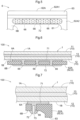
FIG. 1 is a cross-sectional view of a vehicle glass module being attached. -
FIG. 2 is a cross-sectional view of a vehicle glass module according to a first embodiment, showing its main components. -
FIG. 3 is a diagram of a bracket in the first embodiment as viewed from inside a vehicle. -
FIG. 4 is a cross-sectional view of a vehicle glass module according to a first modification of the first embodiment, showing its main components. -
FIG. 5 is a plan view of a vehicle glass module according to a second modification of the first embodiment, showing its main components. -
FIG. 6 is a cross-sectional view of the vehicle glass module according to the second modification of the first embodiment, showing its main components. -
FIG. 7 is a cross-sectional view of a vehicle glass module according to a third modification of the first embodiment, showing its main components. -
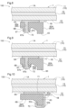
FIG. 8 is a cross-sectional view of a vehicle glass module according to a second embodiment, showing its main components. -
FIG. 9 is a cross-sectional view of a vehicle glass module according to a modification of the second embodiment, showing its main components. -
FIG. 10 is a cross-sectional view of a vehicle glass module according to a third embodiment, showing its main components. -
FIG. 11 is a cross-sectional view of a vehicle glass module according to a modification of the third embodiment, showing its main components. -
FIG. 12 is a cross-sectional view of a vehicle glass module according to a fourth embodiment, showing its main components. -
FIG. 13 is a cross-sectional view of a vehicle glass module according to a first modification of the fourth embodiment, showing its main components. -
FIG. 14 is a cross-sectional view of a vehicle glass module according to a second modification of the fourth embodiment, showing its main components. -
FIG. 15 is a cross-sectional view of a vehicle glass module according to a third modification of the fourth embodiment, showing its main components. -
FIG. 16 is a cross-sectional view of a vehicle glass module according to a fourth modification of the fourth embodiment, showing its main components. - A vehicle glass module according to one embodiment of the present invention will be described below with reference to the drawings. In the present embodiment, a
vehicle glass module 100 for supporting an information obtainer in an automobile (an example of a vehicle) will be described as an example of a vehicle glass module. The structure is not limited to the embodiments below and may be modified in various manners without departing from the spirit and scope of the invention. The direction of gravity may be hereafter referred to as downward, and the direction opposite to the direction of gravity may be referred to as upward. - As shown in
FIG. 1 , thevehicle glass module 100 includes aglass substrate 1 as a windshield of the automobile, and abracket 6 in the form of a frame. Thebracket 6 can receive acover 7 to which an information obtainer is attached. The information obtainer at least irradiates or receives light to obtain information from outside the vehicle. Thecover 7 has an L-shaped cross section, and the information obtainer is fixed to a vertically extending side wall of thecover 7. Thecover 7 holds acamera 8, and is attached to thebracket 6 from inside the vehicle after a harness (not shown) or other components are attached to thebracket 6. This allows thecamera 8 to be accommodated in a space defined by thebracket 6, thecover 7, and theglass substrate 1. - The
glass substrate 1 includes alaminated glass plate 10 and ashield layer 2 disposed along the peripheral edge of an inner surface of thelaminated glass plate 10 to block viewing from outside the vehicle. - In the present embodiment, the camera 8 (imaging device) as an example of an information obtainer is attached to the inside of the vehicle. When the
camera 8 is attached to the inside of the vehicle, an information obtaining area 3 facing thecamera 8 in anopening 23 is defined on theglass substrate 1 to allow passage of light. Thecamera 8 includes an image sensor, such as a charge-coupled device (CCD) or a complementary metal-oxide semiconductor (CMOS), and lenses, and captures images of the surroundings of the vehicle through the information obtaining area 3. The images captured by thecamera 8 are transmitted to an engine control unit, or ECU (not shown), installed on the vehicle. Automobile driving assistance is implemented based on commands from the ECU. - An area different from the information obtaining area 3 includes a
view area 5. Theview area 5 is used for a driver driving the automobile to check traffic conditions. Theview area 5 is disposed on theglass substrate 1 inward from theshield layer 2 in a planar direction of theglass substrate 1. - In the information obtaining area 3, an antifogging film 4 may be attached to the surface of the
glass substrate 1 facing inside the vehicle to reduce light transmission. The antifogging film 4 allows the information obtaining area 3 to have less light transmission than theview area 5. - The
laminated glass plate 10 includes anouter glass plate 11 facing outside the vehicle, aninner glass plate 12 facing inside the vehicle, and anintermediate film 13 between theouter glass plate 11 and theinner glass plate 12. Theintermediate film 13 bonds the surface of theouter glass plate 11 facing outside the vehicle to the surface of theinner glass plate 12 facing inside the vehicle. Theglass substrate 1 has anouter surface 1A on theouter glass plate 11 and aninner surface 1B on theinner glass plate 12. - In the present embodiment, the
outer glass plate 11 is curved to define a convex surface facing outside the vehicle, and theinner glass plate 12 is curved to define a concave surface facing inside the vehicle. Each of theouter glass plate 11 and theinner glass plate 12 is, for example, a plate of heat absorbing glass, clear glass, green glass, or UV green glass. - The
intermediate film 13 is held between theouter glass plate 11 and theinner glass plate 12, and bonds theouter glass plate 11 and theinner glass plate 12 together. Theintermediate film 13 may have a three-layer structure with a softer core layer held between a pair of outer harder layers. Theintermediate film 13 with the multi-layer structure of the softer layer and the harder layers increases the breakage resistance and sound insulation performance of theglass substrate 1. For theintermediate film 13 with the above multi-layer structure of layers having different hardness, the outer harder layers may be formed from a polyvinyl butyral (PVB) resin. The PVB resin has higher adhesion and higher penetration resistance, and may thus be used as a material for the outer layers. The softer core layer may be formed from an ethylene vinyl acetate (EVA) resin, or a polyvinyl acetal resin that is softer than the PVB resin used for the outer layers. - The
shield layer 2 is a dark-colored ceramic laminate. Theshield layer 2 includes abracket receiving area 22 extending inward from the center of the upper peripheral side of thelaminated glass plate 10 in the planar direction. Thebracket 6 is in the form of a frame and is bonded with a bonding member 71 (refer toFIG. 2 ) to thebracket receiving area 22 with no ceramic laminate in theshield layer 2 to surround theopening 23. To reliably block light and prevent deterioration of thebonding member 71, theshield layer 2 may have a thickness of, for example, 20 to 100 µm. - As shown in
FIGs. 1 to 3 , thebracket 6 is in the form of a rectangular frame including anattachment opening 61 to receive thecover 7 holding thecamera 8. Thebracket 6 includes arectangular body 62 surrounding theattachment opening 61. Thebody 62 has anupper side 62A, alower side 62B, aleft side 62C, and aright side 62D. Theupper side 62A has an outer edge 62A1 at its upper end, and thelower side 62B has an outer edge 62B1 at its lower end. Thebody 62 includes a first protrusion 63 (an example of a protrusion) on theupper side 62A for contact with an upper end of thecover 7, a second protrusion 64 (an example of the protrusion) on thelower side 62B for contact with a lower end of thecover 7, andengagements 65 for supporting and fixing thecover 7 on theleft side 62C and theright side 62D. - As shown in
FIG. 1 , thebracket 6 surrounds theopening 23 in theshield layer 2. As shown inFIG. 2 , thebracket 6 has afirst surface 6A bonded to theinner surface 1B of theglass substrate 1 with the bondingmember 71, and asecond surface 6B opposite to theglass substrate 1. Thefirst surface 6A of thebracket 6 is flat, and thebonding member 71 is in close contact with thefirst surface 6A. Thebody 62 is bonded to the shield layer 2 (bracket receiving area 22) or to theglass substrate 1 with the bondingmember 71. In this structure, thebracket 6 is fixed to the shield layer 2 (bracket receiving area 22) to be entirely or at least partially shielded by theshield layer 2. Theshield layer 2 laminated on theinner glass plate 12 of thelaminated glass plate 10 is not shown in thevehicle glass module 100 inFIG. 2 (the same applies toFIG. 4 and subsequent figures). - The
bracket 6 is formed from a material containing a thermoplastic resin. Examples of the thermoplastic resin include a polybutylene terephthalate (PBT) resin, a polypropylene (PP) resin, a polyethylene (PE) resin, a polycarbonate (PC) resin, a polyamide (PA) resin, and a synthetic resin such as a combination of the above thermoplastic resins or a combination of the above thermoplastic resins and other types of resin. Thebracket 6 containing such a thermoplastic resin softens under heat and is elastic at room temperature, and is thus easily molded under heat. Thebracket 6 may be specifically formed from a thermoplastic polyester resin material with an ester bonding structure. Examples of the thermoplastic polyester resin include a PBT resin and a polyethylene terephthalate (PET) resin. An additive to mix with a thermoplastic resin may be, for example, an inorganic filler. With a thermoplastic resin containing an inorganic filler, thebracket 6 can have higher heat resistance and strength. - As shown in
FIGs. 2 and3 , thebracket 6 has through-holes 66 connecting thefirst surface 6A with thesecond surface 6B. In the present embodiment, as shown inFIG. 3 , multiple (three in the present embodiment) through-holes 66 are arranged at intervals in each of theupper side 62A and thelower side 62B of thebody 62. The multiple through-holes 66 are disposed in a lower area 62A2 of theupper side 62A below thefirst protrusion 63, and in an upper area 62B2 of thelower side 62B above thesecond protrusion 64. - As shown in
FIG. 2 , thebracket 6 includes asupport 72 connected to thebonding member 71. Thesupport 72 is in contact with thesecond surface 6B and supports the weight of thebracket 6. The bondingmember 71 on thefirst surface 6A and thesupport 72 on thesecond surface 6B are connected through the through-holes 66. The bondingmember 71 is disposed in the through-holes 66 and in an area of thefirst surface 6A, and the area is adjacent to the through-holes 66. Thesupport 72 is disposed in the through-holes 66 and in an area of thesecond surface 6B, and the area is adjacent to the through-holes 66. - The bonding
member 71 on thefirst surface 6A of thebracket 6 is an adhesive. Thesupport 72 on thesecond surface 6B is formed from the same material as the adhesive as the bondingmember 71. Thesupport 72 is continuous with the adhesive. Each of thebonding member 71 and thesupport 72 is an adhesive in the form of fluid having a predetermined viscosity and may be, for example, a urethane resin adhesive or an epoxy resin adhesive. In particular, an epoxy resin adhesive has higher viscosity, and is less likely to flow. The bondingmember 71 and thesupport 72 may be a single layer without a primer layer as an adhesion aid. The bondingmember 71 and thesupport 72 as a single layer with no primer layer can reduce work-hours for bonding. Further, the bondingmember 71 and thesupport 72 as a single layer can avoid concerns such as instability of materials at the interface between the layers, unlike thebonding member 71 and thesupport 72 as a multi-layer including a primer layer. - A method for manufacturing the
vehicle glass module 100 includes a glass plate forming process, a bracket molding process, and a bonding process. - In the glass plate forming process, the
glass substrate 1 with theshield layer 2 is manufactured. First, each of theouter glass plate 11 and theinner glass plate 12 is cut into a predetermined shape. A ceramic material as theshield layer 2 is then printed (applied) on the surface of theinner glass plate 12 facing inside the vehicle by, for example, screen printing (also refer toFIG. 1 ). Subsequently, each of theglass plates intermediate film 13 is then placed between theglass plates glass substrate 1 that is curved and includes theshield 2 with theopening 23. - In the bracket molding process, a thermoplastic resin is poured into a mold for a known injection molding process. This forms the
bracket 6 with thefirst surface 6A as a smooth flat surface. - In the bonding process, the bonding
member 71 is applied to, for example, theupper side 62A and thelower side 62B of thefirst surface 6A of thebracket 6, and double-sided tape (not shown) is attached to theleft side 62C and theright side 62D. Thefirst surface 6A of thebracket 6 is placed to surround theopening 23 in the shield layer 2c, and bonded to theshield layer 2 in theglass substrate 1 with the bondingmember 71 and the double-sided tape. In this state, the double-sided tape is instantly bonded to theglass substrate 1, and thebracket 6 is prefixed to theglass substrate 1. In this state, theupper side 62A and thelower side 62B are in contact with theshield layer 2, allowing thebonding member 71 to spread along thefirst surface 6A to fill the through-holes 66 and overflow from the through-holes 66 to thesecond surface 6B. The bondingmember 71 then spreads continuously to thesecond surface 6B adjacent to the through-holes 66. When thebonding member 71 remains in the through-holes 66, an adhesive of the same material as the bondingmember 71 fills the through-holes 66 from thesecond surface 6B, and spreads continuously from the through-holes 66 to thesecond surface 6B adjacent to the through-holes 66. - After a predetermined period of time passes, the bonding
member 71 in the form of fluid solidifies, firmly fixing theupper side 62A and thelower side 62B of thefirst surface 6A of thebracket 6 to theglass substrate 1. Further, the bondingmember 71 spread to thesecond surface 6B forms thesupport 72. Thesupport 72 is in contact with thesecond surface 6B to support the weight of thebracket 6. - Subsequently, the
camera 8 is attached to thebracket 6. Thecover 7 is finally attached to theengagements 65 on thebracket 6. This completes manufacture of thevehicle glass module 100 for supporting thecamera 8 disposed in the vehicle. - To fix the
bracket 6 to theinner surface 1B of theglass substrate 1, thevehicle glass module 100 according to the present embodiment includes thebonding member 71 bonding thefirst surface 6A of thebracket 6 to theinner surface 1B of theglass substrate 1, and thesupport 72 connected to thebonding member 71 and in contact with thesecond surface 6B of thebracket 6. This allows thebracket 6 to be bonded to theglass substrate 1 with the bondingmember 71, and allows thebracket 6 to be held by thesupport 72 connected to thebonding member 71. In particular, when thevehicle glass module 100 is, for example, exposed to sunlight or has a large temperature difference in a short time between the inside and the outside of the vehicle during air-conditioning in the vehicle, the bondingmember 71 repeatedly contracts and expands. The bonding strength between thebracket 6 and thebonding member 71 may then be lower than the bonding strength between theglass substrate 1 and thebonding member 71, possibly causing thebracket 6 supporting the load of theheavy camera 8 to drop. In the present embodiment, thesupport 72 is connected to thebonding member 71 and is in contact with thesecond surface 6B of thebracket 6 to support the weight of thebracket 6. Thesupport 72 connected to thebonding member 71 thus remains in contact with thesecond surface 6B of thebracket 6 when thebracket 6 detaches from the bondingmember 71. This prevents thebracket 6 from dropping. Thebracket 6 includes thesupport 72 in contact with thesecond surface 6B of thebracket 6. This simple structure appropriately supports thebracket 6 on theglass substrate 1. - In the present embodiment, the bonding
member 71 is an adhesive. Thesupport 72 connected to thebonding member 71 is formed from the same material as the bonding member 71 (adhesive). Thesupport 72 is continuous with the bonding member 71 (adhesive). Thus, thesupport 72 has a simple structure. When each of thebonding member 71 and thesupport 72 is an adhesive, thesupport 72 is firmly connected to thebonding member 71. This structure more appropriately supports thebracket 6 on theglass substrate 1. - In the present embodiment, the bonding
member 71 and thesupport 72 are connected through the through-holes 66 in thebracket 6. This structure easily connects the bondingmember 71 and thesupport 72 to each other. Further, the area of thefirst surface 6A of thebracket 6 is connected to the area of thesecond surface 6B of thebracket 6 through the through-holes 66, allowing thesupport 72 to support thebracket 6 more firmly. - As shown in
FIG. 4 , each through-hole 66 may be flared from thefirst surface 6A toward thesecond surface 6B. When each through-hole 66 in thebracket 6 is flared from thefirst surface 6A toward thesecond surface 6B of thebracket 6 as in a first modification, the through-hole 66 has a diameter increasing toward thesecond surface 6B. This allows thesupport 72 in contact with thesecond surface 6B of thebracket 6 to be guided along the flared portion in the corresponding through-hole 66 and placed closer to thebonding member 71. Thesupport 72 is thus more easily connected to thebonding member 71 in the corresponding through-hole 66. - When the
bonding member 71 is, for example, an adhesive, and when thebracket 6 is simply pressed against theglass substrate 1 with the adhesive (bonding member 71) between thefirst surface 6A of thebracket 6 and theglass substrate 1, the adhesive (bonding member 71) filled in each through-hole 66 is placed closer to thesecond surface 6B of thebracket 6. This allows thesupport 72 to be easily connected to thebonding member 71. - In the
bracket 6, as shown inFIGs. 5 and 6 , thesupport 72 may connect the multiple through-holes 66 with one another on thesecond surface 6B. In a second modification, thesupport 72 connects the multiple through-holes 66 with one another on thesecond surface 6B to increase the connection between the bondingmember 71 and thesupport 72. This structure more appropriately supports thebracket 6 on theglass substrate 1. - As shown in
FIG. 7 , the bondingmember 71 and thesupport 72 may have arecess 73 from an outer surface of thesupport 72 toward the corresponding through-hole 66. To form therecess 73, for example, a core in the form of a rod is placed in the through-hole 66, and the core has a smaller diameter than the through-hole 66. Therecess 73 extends from thesupport 72 toward the bondingmember 71. This reduces the amount of the adhesive used for thebonding member 71 and thesupport 72. - In a second embodiment, as shown in
FIG. 8 , thesecond surface 6B of thebracket 6 includes a third protrusion 67 (an example of the protrusion) protruding away from thefirst surface 6A. Thebracket 6 has the through-holes 66 connecting thefirst surface 6A with thesecond surface 6B, and thethird protrusion 67 protrudes from anouter edge 66a of each through-hole 66. Theouter edge 66a of the through-hole 66 defines the boundary between the through-hole 66 and a base plane of thesecond surface 6B. Thethird protrusion 67 has ahole 67a continuous with the through-hole 66. Thesupport 72 is connected to thebonding member 71 through the through-hole 66 and thehole 67a, and is in contact with adistal end face 67b of thethird protrusion 67. Thedistal end face 67b defines a part of thesecond surface 6B of thebracket 6. - When the
bracket 6 has the through-holes 66 each connecting thefirst surface 6A with thesecond surface 6B, and when thethird protrusion 67 protrudes from theouter edge 66a of each through-hole 66 as in the present embodiment, the bondingmember 71 and thesupport 72 can be connected in the through-hole 66 and in thehole 67a (inside) in thethird protrusion 67 continuous with the through-hole 66. This reliably connects the bondingmember 71 and thesupport 72 to each other. - When the
second surface 6B of thebracket 6 includes thethird protrusion 67 protruding away from thefirst surface 6A and when thesupport 72 is in contact with thethird protrusion 67, thesupport 72 can be connected to thebonding member 71 through thethird protrusion 67 on thebracket 6. This increases the area of contact of thebonding member 71 and thesupport 72 with thebracket 6. Thethird protrusion 67 protrudes from thesecond surface 6B. Thecover 7 holding thecamera 8 may be engaged with thethird protrusion 67. In this case, thethird protrusion 67 is likely to receive a concentrated load of thecamera 8. Thesupport 72 in contact with thethird protrusion 67 can reliably prevent thebracket 6 from dropping. Thebracket 6 can thus be held more firmly by the bondingmember 71 and thesupport 72. - As shown in
FIG. 9 , thesupport 72 may be in contact with thethird protrusion 67, and may be continuous with an area of thesecond surface 6B. The area is adjacent to thethird protrusion 67. In this modification, thesupport 72 is in contact with the extended area of thesecond surface 6B of thebracket 6, allowing thebracket 6 to be held still more firmly by thesupport 72. - In a third embodiment, as shown in
FIG. 10 , the bondingmember 71 and thesupport 72 are connected through anouter surface 63a of thefirst protrusion 63 on the outer edge 62A1 of thebracket 6. Thefirst protrusion 63 has theouter surface 63a on the outer edge of thebracket 6, adistal end face 63b, and aninner surface 63c opposite to theouter surface 63a. The bondingmember 71 extends from thefirst surface 6A to theouter surface 63a, and thesupport 72 is disposed from theouter surface 63a to theinner surface 63c through thedistal end face 63b. Thedistal end face 63b and theinner surface 63c define a part of thesecond surface 6B of thebracket 6. Although not shown, thesupport 72 may extend to thedistal end face 63b of thefirst protrusion 63, or may be continuous with an area of thesecond surface 6B, and the area is adjacent to thefirst protrusion 63. - When the
cover 7 holding thecamera 8 is attached to thebracket 6 and supported, thebracket 6 is likely to receive a greater load of thecamera 8 at outer edge positions of thebracket 6. In the present embodiment, thefirst protrusion 63 in contact with thesupport 72 is disposed on the outer edge 62A1 of thebracket 6. This structure allows thefirst protrusion 63 to increase the strength of the outer edge 62A1 of thebracket 6 and allows thesupport 72 placed on thefirst protrusion 63 to appropriately support thebracket 6. - As shown in
FIG. 11 , in this modification, thefirst protrusion 63 has aconnection hole 68 connecting theouter surface 63a, which is continuous with thefirst surface 6A, with theinner surface 63c. Theconnection hole 68 extends through thefirst protrusion 63 in a direction intersecting with a direction in which thefirst protrusion 63 protrudes. The bondingmember 71 and thesupport 72 are connected through theouter surface 63a of thefirst protrusion 63, and thebonding member 71 enters (fills) theconnection hole 68 to form thesupport 72. Theconnection hole 68 defines a part of thesecond surface 6B of thebracket 6. Although not shown, thesupport 72 may extend to be in contact with theinner surface 63c of thefirst protrusion 63, or may be continuous with the area of thesecond surface 6B. The area is adjacent to thefirst protrusion 63. - In this modification, the bonding
member 71 and thesupport 72 are connected through theouter surface 63a of thefirst protrusion 63. This structure easily connects the bondingmember 71 and thesupport 72 to each other. Thesupport 72 includes thebonding member 71 filling theconnection hole 68 in thefirst protrusion 63 on the outer edge 62A1 of thebracket 6. The bonding member 71 (support 72) in theconnection hole 68 can thus support thebracket 6 still more firmly. - In a fourth embodiment, as shown in
FIG. 12 , thesupport 72 is a member formed from a material different from the material of thebonding member 71. In the present embodiment, as in the first embodiment, thebracket 6 has the through-holes 66 each connecting thefirst surface 6A with thesecond surface 6B. In the present embodiment, thesupport 72 is arivet 81 including ahead 81a, ashank 81b, and adistal end 81c. Therivet 81 is formed from, for example, a resin or metal. Theshank 81b has substantially the same shape as each through-hole 66. Examples of the resin for therivet 81 include a PBT resin and a polyamide resin including nylon. Examples of the metal for therivet 81 include iron, stainless steel, and brass. Therivet 81 is received in the corresponding through-hole 66 in thebracket 6. Thedistal end 81c is then deformed with, for example, an attachment tool to fix therivet 81 to thebracket 6. After therivet 81 is fixed to thebracket 6, thebracket 6 with the bondingmember 71 on the first surface 6Ais then pressed against theinner surface 1B of theglass substrate 1, forming thevehicle glass module 100. Thedistal end 81c of therivet 81 is thus connected to thebonding member 71, and thehead 81a of therivet 81 comes into contact with thesecond surface 6B of thebracket 6. In this structure, therivet 81 connected to thebonding member 71 with thehead 81a in contact with thesecond surface 6B supports the weight of thebracket 6. - In the present embodiment, a
second bonding member 74 is further disposed on thehead 81a of therivet 81 and in an area of thesecond surface 6B, and the area is adjacent to thehead 81a. In other words, thesupport 72 includes therivet 81 and thesecond bonding member 74. Similarly to thebonding member 71, thesecond bonding member 74 is an adhesive, and is formed from the same material as the bondingmember 71. Therivet 81 and thesecond bonding member 74 both in contact with thesecond surface 6B support the weight of thebracket 6. - When the
support 72 is a member formed from a material different from the material of thebonding member 71 as in the present embodiment, thesupport 72 can be a member selected from a wider range of members, and the member as thesupport 72 can be appropriately selected based on, for example, the weight of the device to be attached to thebracket 6. Further, when thesupport 72 includes multiple members (therivet 81 and the second bonding member 74) formed from different materials as in the present embodiment, thesupport 72 may include members selected appropriately for the respective areas of thesupport 72. For example, a member for a connection area of thesupport 72 with the bondingmember 71 may be different from a member for an area of thesupport 72 in contact with thesecond surface 6B of thebracket 6. - As shown in
FIG. 13 , therivet 81 may be in the form of a split pin with theshank 81b and thedistal end 81c divided by asplit groove 81d. Thedistal end 81c of therivet 81 is tapered. Therivet 81 with the above structure has thedistal end 81c passed through the through-hole 66 to be released from the through-hole 66 and expand toward the outer periphery, automatically engaged with thefirst surface 6A of thebracket 6. In a first modification, therivet 81 can be simply fixed to thebracket 6 without any attachment tool. As in the fourth embodiment, therivet 81 in the first modification is also formed from a resin or metal. - In the first modification, the through-
hole 66 in thebracket 6 may be, for example, tapered from thesecond surface 6B toward thefirst surface 6A with its inner diameter larger at its opening end on thesecond surface 6B and gradually reduced toward thefirst surface 6A. Therivet 81 with this structure has thedistal end 81c guided through the through-hole 66 from thesecond surface 6B to thefirst surface 6A, and can be easily attached to thebracket 6 through the through-hole 66. - In the first modification as well, the
second bonding member 74 is further disposed on thehead 81a of therivet 81 and in an area of thesecond surface 6B, and the area is adjacent to thehead 81a. In other words, thesupport 72 includes therivet 81 and thesecond bonding member 74. Therivet 81 and thesecond bonding member 74 both in contact with thesecond surface 6B support the weight of thebracket 6. In the structure of this first modification, the bondingmember 71 is disposed inside theshank 81b of therivet 81 in the through-hole 66, and therivet 81 can thus be connected to thebonding member 71 more firmly. - As shown in
FIG. 14 , thesupport 72 may include abolt 82 as a member formed from a material different from the material of thebonding member 71. Thebolt 82 includes ahead 82a, ashank 82b, and adistal end 82c. Thebolt 82 in the first modification is formed from the same material as therivet 81 in the fourth embodiment, and theshank 82b has substantially the same shape as each through-hole 66. Thebolt 82 is screwed into the through-hole 66 from thesecond surface 6B to be fixed in the through-hole 66. Thebolt 82 has itsdistal end 82c connected to thebonding member 71 inside the through-hole 66. - In a second modification, the
second bonding member 74 is further disposed on thehead 82a of thebolt 82 and in an area of thesecond surface 6B, and the area is adjacent to thehead 82a. In other words, thesupport 72 includes thebolt 82 and thesecond bonding member 74, and thehead 82a of thebolt 82 and thesecond bonding member 74 both in contact with thesecond surface 6B support the weight of thebracket 6. - As shown in
FIG. 15 , thesupport 72 may include abolt 83 as a member formed from a material different from the material of thebonding member 71. Thebolt 83 may be closer to theinner surface 1B of theglass substrate 1 than to thefirst surface 6A. Thebolt 83 includes ahead 83a, ashank 83b, and adistal end 83c. Thebolt 83 in the second modification is formed from the same material as therivet 81 in the fourth embodiment, and theshank 82b has substantially the same shape as each through-hole 66. Thebolt 83 is screwed into the through-hole 66 from thesecond surface 6B to be fixed in the through-hole 66. Thebolt 83 has thedistal end 82c protruding from the through-hole 66, and is connected to thebonding member 71 between thefirst surface 6A and theinner surface 1B. Thehead 83a of thebolt 83 is in contact with thesecond surface 6B to support the weight of thebracket 6. In the structure according to the second modification, thebolt 83 is more easily to come in contact with the bondingmember 71 than in the first modification. Thebolt 83 can thus be connected to thebonding member 71 more firmly. - As shown in
FIG. 16 , thesupport 72 may include abolt 84 as a member formed from a material different from the material of thebonding member 71. Thebolt 84 may include ashank 84b and adistal end 84c each having a smaller diameter than the through-hole 66. Thebolt 84 in the third modification is formed from the same material as therivet 81 in the fourth embodiment. Theshank 84b and thedistal end 84c are received in the through-hole 66 filled with the bondingmember 71, followed by the bondingmember 71 solidifying to connect thebolt 84 to thebonding member 71. In this structure, thebolt 84 has ahead 84a in contact with thesecond surface 6B to support the weight of thebracket 6. In the structure according to the third modification, the bondingmember 71 surrounds theshank 84b of thebolt 84 in the through-hole 66, and thebolt 84 can thus be connected to thebonding member 71 more firmly. Other Embodiments - (1) When each of the
bonding member 71 and thesupport 72 is an adhesive, or when thesupport 72 is formed from a material other than the adhesive, the bondingmember 71 may have a smaller difference in linear expansion coefficient with thesupport 72 than with thefirst surface 6A of thebracket 6. In this structure, when thevehicle glass module 100 is affected by varying temperatures resulting from, for example, exposure to sunlight, the bondingmember 71 has a smaller shearing stress with thesupport 72 than with thefirst surface 6A of thebracket 6. In the above structure, when the bonding strength between thebracket 6 and thebonding member 71 is reduced, thesupport 72 connected to thebonding member 71 can support thebracket 6 to prevent thebracket 6 from dropping. This structure more appropriately supports thebracket 6 on theglass substrate 1. - (2) In the fourth embodiment and its second and third modifications, the
rivet 81, thebolt 82, and thebolt 83 as thesupport 72 include therespective bodies rivet 81, thebolt 82, and thebolt 83 may have a through-hole connecting thefirst surface 6A and thesecond surface 6B. In this structure, each of therivet 81, thebolt 82, and thebolt 83 can connect thebonding member 71 and thesecond bonding member 74 through the corresponding through-hole defined inside therivet 81 or thebolt support 72 including thesecond bonding member 74 and therivet 81 or other members can be connected to thebonding member 71 more firmly. Further, having a recess on thefirst surface 6A or on thesecond surface 6B, each of therivet 81, thebolt 82, and thebolt 83 has an increased area bonded to thebonding member 71 or to thesecond bonding member 74. In this structure, each of therivet 81, thebolt 82, and thebolt 83 can thus be more firmly connected to thebonding member 71 or to thesecond bonding member 74. - (3) In the fourth embodiment and its first modification, the
second bonding member 74 is further disposed on thehead 81a of therivet 81 and in the area of thesecond surface 6B, and the area is adjacent to thehead 81a. In some embodiments, thesecond bonding member 74 may be eliminated. - (4) In the above embodiments, the
bracket 6 is bonded to theshield layer 2 in theglass substrate 1. In some embodiments, theglass substrate 1 may not include theshield layer 2. When theglass substrate 1 includes noshield layer 2, or when theglass substrate 1 includes theshield layer 2 but theshield layer 2 is not disposed at the bonding position of thebracket 6, thebracket 6 may be bonded directly to theinner glass plate 12 of thelaminated glass plate 10 in theglass substrate 1. - (5) In the above embodiments, the
vehicle glass module 100 supports thecamera 8 as the information obtainer. In some embodiments, the information obtainer may be one of various sensors including a range sensor, such as a laser radar or a supersonic sensor, or a combination of multiple information obtainers. - (6) In the above embodiments, the
glass substrate 1 includes thelaminated glass plate 10 as theouter glass plate 11 and theinner glass plate 12 bonded to each other with theintermediate film 13 between them. In some embodiments, theglass substrate 1 may be, for example, a single glass plate such as a rear glass plate in an automobile. Theglass substrate 1 may have any shape other than the curved shape. - The technique according to one or more embodiments of the present invention is applicable to a vehicle glass module for supporting an information obtainer in a vehicle, and a method for manufacturing the vehicle glass module.
-
- 1 glass substrate
- 6 bracket
- 6A first surface
- 6B second surface
- 10 laminated glass plate
- 11 outer glass plate
- 12 inner glass plate
- 13 intermediate film
- 61 attachment hole
- 62 body
- 62Aupper side
- 62A1 outer edge
- 62B lower side
- 63 first protrusion (protrusion)
- 64 second protrusion (protrusion)
- 66 through-hole
- 67 third protrusion (protrusion)
- 67a distal end
- 68 connection hole
- 71 bonding member
- 72 support
- 74 second bonding member
- 81 rivet
- 82, 83, 84 bolt
- 100 vehicle glass module
Claims (13)
- A vehicle glass module for supporting an information obtainer in a vehicle, the vehicle glass module comprising:a glass substrate having an outer surface and an inner surface; anda bracket having a first surface bonded to the inner surface of the glass substrate with a bonding member and a second surface opposite to the glass substrate,the bracket including a support connected to the bonding member, the support being in contact with the second surface and supporting a weight of the bracket.
- The vehicle glass module according to claim 1, whereinthe bonding member is an adhesive, andthe support comprises a same material as the adhesive, and the support is continuous with the adhesive.
- The vehicle glass module according to claim 1 or claim 2, whereinthe bracket has at least one through-hole connecting the first surface with the second surface,the bonding member and the support are connected to each other through the at least one through-hole,the bonding member is disposed in the at least one through-hole and in an area of the first surface, and the area is adjacent to the at least one through-hole, andthe support is disposed in the at least one through-hole and in an area of the second surface, and the area is adjacent to the at least one through-hole.
- The vehicle glass module according to claim 3, whereinthe bracket has the at least one through-hole being a plurality of through-holes, andthe support connects the plurality of through-holes with one another on the second surface.
- The vehicle glass module according to claim 3 or claim 4, wherein
the at least one through-hole is flared from the first surface toward the second surface. - The vehicle glass module according to any one of claims 1 to 5, whereinthe second surface includes a protrusion protruding away from the first surface, andthe support is in contact with the protrusion.
- The vehicle glass module according to claim 6, wherein
the support is continuous with an area of the second surface, and the area is adjacent to the protrusion. - The vehicle glass module according to claim 6 or claim 7, whereinthe bracket has a through-hole connecting the first surface with the second surface, andthe protrusion protrudes from an outer edge of the through-hole.
- The vehicle glass module according to any one of claims 6 to 8, wherein
the protrusion is on an outer edge of the bracket. - The vehicle glass module according to any one of claims 6 to 8, whereinthe protrusion is on an outer edge of the bracket,the protrusion has a connection hole extending through the protrusion in a direction intersecting with a direction in which the protrusion protrudes, andthe support includes the bonding member entering the connection hole.
- The vehicle glass module according to any one of claims 1 to 10, wherein
the bonding member has a smaller difference in linear expansion coefficient with the support than with the first surface. - The vehicle glass module according to any one of claims 1 to 11, wherein
the support includes a plurality of members comprising different materials. - The vehicle glass module according to any one of claims 1 to 12, wherein
the support includes a member comprising a material different from a material of the bonding member.
Applications Claiming Priority (2)
| Application Number | Priority Date | Filing Date | Title |
|---|---|---|---|
| JP2022008187 | 2022-01-21 | ||
| PCT/JP2023/000997 WO2023140220A1 (en) | 2022-01-21 | 2023-01-16 | Vehicle glass module |
Publications (2)
| Publication Number | Publication Date |
|---|---|
| EP4467370A1 true EP4467370A1 (en) | 2024-11-27 |
| EP4467370A4 EP4467370A4 (en) | 2025-11-19 |
Family
ID=87348755
Family Applications (1)
| Application Number | Title | Priority Date | Filing Date |
|---|---|---|---|
| EP23743214.1A Pending EP4467370A4 (en) | 2022-01-21 | 2023-01-16 | VEHICLE GLASS MODULE |
Country Status (5)
| Country | Link |
|---|---|
| US (1) | US20250091325A1 (en) |
| EP (1) | EP4467370A4 (en) |
| JP (1) | JPWO2023140220A1 (en) |
| CN (1) | CN118591468A (en) |
| WO (1) | WO2023140220A1 (en) |
Families Citing this family (2)
| Publication number | Priority date | Publication date | Assignee | Title |
|---|---|---|---|---|
| CN118683296A (en) * | 2023-03-24 | 2024-09-24 | 本田技研工业株式会社 | vehicle |
| US12418712B2 (en) | 2023-11-14 | 2025-09-16 | Honda Motor Co., Ltd. | Camera assembly for vehicle and vehicle including same |
Family Cites Families (8)
| Publication number | Priority date | Publication date | Assignee | Title |
|---|---|---|---|---|
| FR2629149B3 (en) * | 1988-03-28 | 1990-10-12 | Ecia Equip Composants Ind Auto | DEVICE FOR JOINING PARTS, PARTICULARLY IN SYNTHETIC MATERIALS, USING A RESIN |
| DE10306957A1 (en) * | 2003-02-19 | 2004-09-09 | Webasto Vehicle Systems International Gmbh | Window assembly for a vehicle and manufacturing method therefor |
| JP2005256451A (en) * | 2004-03-12 | 2005-09-22 | Hori Glass Kk | Supporting structure for automobile window glass |
| DE102006056501B4 (en) * | 2006-11-30 | 2012-05-03 | Saint-Gobain Sekurit Deutschland Gmbh & Co. Kg | Laminated glass pane with an attachment device for an antenna inserted into a through hole |
| JP2011165055A (en) * | 2010-02-12 | 2011-08-25 | Toyota Industries Corp | Breakage detector for vehicle window glass |
| JP2017106216A (en) * | 2015-12-09 | 2017-06-15 | スリーエム イノベイティブ プロパティズ カンパニー | Window structure as well as building and vehicle with the same |
| EP3450229A4 (en) | 2016-04-27 | 2019-09-25 | Agc Inc. | LAMINATE PLATE EQUIPPED WITH A SUPPORT |
| US10534253B2 (en) * | 2017-11-10 | 2020-01-14 | Denso Corporation | Camera module which includes lens units and configured to be mounted on inside of windshiled of vehicle |
-
2023
- 2023-01-16 JP JP2023575239A patent/JPWO2023140220A1/ja active Pending
- 2023-01-16 EP EP23743214.1A patent/EP4467370A4/en active Pending
- 2023-01-16 US US18/728,851 patent/US20250091325A1/en active Pending
- 2023-01-16 WO PCT/JP2023/000997 patent/WO2023140220A1/en not_active Ceased
- 2023-01-16 CN CN202380018166.3A patent/CN118591468A/en active Pending
Also Published As
| Publication number | Publication date |
|---|---|
| EP4467370A4 (en) | 2025-11-19 |
| US20250091325A1 (en) | 2025-03-20 |
| WO2023140220A1 (en) | 2023-07-27 |
| CN118591468A (en) | 2024-09-03 |
| JPWO2023140220A1 (en) | 2023-07-27 |
Similar Documents
| Publication | Publication Date | Title |
|---|---|---|
| EP4467370A1 (en) | Vehicle glass module | |
| US11729483B2 (en) | Photosensitive component, and camera module and manufacturing method therefor | |
| US20220124229A1 (en) | Vehicular camera module | |
| KR102780248B1 (en) | Vehicle Mounted Camera | |
| JP4983756B2 (en) | Electronic circuit equipment | |
| CN108367544B (en) | Method of making composite glass panels for motor vehicles | |
| KR102320910B1 (en) | Camera module, photosensitive assembly, photosensitive assembly alignment plate, forming die and manufacturing method thereof | |
| US20160256958A1 (en) | Method for Producing a Component Connection from Two Different Materials, and a Corresponding Component Connection | |
| JP2007506126A (en) | Optical module having a spacing element between a semiconductor element housing and a lens unit | |
| CN109963748B (en) | Vehicle attachment with integrated camera module | |
| JP4990831B2 (en) | Lens assembly and imaging device | |
| CN110418725A (en) | Laminated glass for use in vehicles with rearview mirror | |
| CN105163007A (en) | Method for lens objective in camera module and prefocusing lens holder for motor vehicle | |
| JP2025100833A (en) | Lens unit, camera module, imaging system and mobile object | |
| KR102780944B1 (en) | Vehicle Mounted Camera | |
| CN116605020A (en) | Roof module and motor vehicle comprising such a roof module | |
| US20230247275A1 (en) | Vehicular camera module | |
| WO2019047960A1 (en) | Camera module, and photosensitive component, electronic device, forming mold and manufacturing method thereof | |
| JP3216692U (en) | Vehicle glazing unit with support for attaching accessories and support | |
| CN115052804A (en) | Roof for a motor vehicle, motor vehicle having a roof, assembly for a roof and method for assembling a roof | |
| US20220091270A1 (en) | Vehicle-integrated lidar system | |
| US20160312526A1 (en) | Vehicular resin glass | |
| JP6803260B2 (en) | In-vehicle camera module | |
| JP7810181B2 (en) | Bracket and information acquisition module | |
| CN224191998U (en) | Camera module and electronic equipment |
Legal Events
| Date | Code | Title | Description |
|---|---|---|---|
| STAA | Information on the status of an ep patent application or granted ep patent |
Free format text: STATUS: THE INTERNATIONAL PUBLICATION HAS BEEN MADE |
|
| PUAI | Public reference made under article 153(3) epc to a published international application that has entered the european phase |
Free format text: ORIGINAL CODE: 0009012 |
|
| STAA | Information on the status of an ep patent application or granted ep patent |
Free format text: STATUS: REQUEST FOR EXAMINATION WAS MADE |
|
| 17P | Request for examination filed |
Effective date: 20240821 |
|
| AK | Designated contracting states |
Kind code of ref document: A1 Designated state(s): AL AT BE BG CH CY CZ DE DK EE ES FI FR GB GR HR HU IE IS IT LI LT LU LV MC ME MK MT NL NO PL PT RO RS SE SI SK SM TR |
|
| DAV | Request for validation of the european patent (deleted) | ||
| DAX | Request for extension of the european patent (deleted) | ||
| A4 | Supplementary search report drawn up and despatched |
Effective date: 20251020 |
|
| RIC1 | Information provided on ipc code assigned before grant |
Ipc: B60J 1/00 20060101AFI20251014BHEP Ipc: B60R 1/00 20220101ALI20251014BHEP |